EP1201327A2 - Vorrichtung zur Beeinflussung der Abwurf-Fallposition von in einen Bundbildeschacht abgeworfenen Walzdrahtwindungen - Google Patents
Vorrichtung zur Beeinflussung der Abwurf-Fallposition von in einen Bundbildeschacht abgeworfenen Walzdrahtwindungen Download PDFInfo
- Publication number
- EP1201327A2 EP1201327A2 EP01123190A EP01123190A EP1201327A2 EP 1201327 A2 EP1201327 A2 EP 1201327A2 EP 01123190 A EP01123190 A EP 01123190A EP 01123190 A EP01123190 A EP 01123190A EP 1201327 A2 EP1201327 A2 EP 1201327A2
- Authority
- EP
- European Patent Office
- Prior art keywords
- conveyor
- windings
- bbs
- brush
- fee
- Prior art date
- Legal status (The legal status is an assumption and is not a legal conclusion. Google has not performed a legal analysis and makes no representation as to the accuracy of the status listed.)
- Withdrawn
Links
Images


Classifications
-
- B—PERFORMING OPERATIONS; TRANSPORTING
- B21—MECHANICAL METAL-WORKING WITHOUT ESSENTIALLY REMOVING MATERIAL; PUNCHING METAL
- B21C—MANUFACTURE OF METAL SHEETS, WIRE, RODS, TUBES, PROFILES OR LIKE SEMI-MANUFACTURED PRODUCTS OTHERWISE THAN BY ROLLING; AUXILIARY OPERATIONS USED IN CONNECTION WITH METAL-WORKING WITHOUT ESSENTIALLY REMOVING MATERIAL
- B21C47/00—Winding-up, coiling or winding-off metal wire, metal band or other flexible metal material characterised by features relevant to metal processing only
- B21C47/02—Winding-up or coiling
- B21C47/10—Winding-up or coiling by means of a moving guide
- B21C47/14—Winding-up or coiling by means of a moving guide by means of a rotating guide, e.g. laying the material around a stationary reel or drum
- B21C47/146—Controlling or influencing the laying pattern of the coils
Definitions
- the invention relates to a device for influencing the drop position of wire rod windings that are roughly horizontal on a conveyor overlying, in one, below the end of the conveyor and, in Transport direction thrown behind this vertically standing bundle shaft become.
- Devices of this type have become known in numerous forms of training; they consistently pursue the goal, the wire rod twists after this have left the conveyor during their fall movement into the bundle shaft so that they are approximately concentric to its vertical Center axis come to rest on each other and a corresponding one Form a collar with cylindrical dimensions, where necessary, offset from one another in a circle, lie on top of each other in presettable laying patterns and thus the layer density the wire windings and the vertical stability of the resulting wire bundle enlarge.
- DE 196 20 578 A1 describes a device in which the vertical Distance and below the discharge end of the conveyor, above the opening a cylindrical body with a funnel-shaped opening is arranged in a horizontal plane, radial to the vertical The middle of the bundle shaft can be moved and tilted at an angle to it.
- EP 04 42 835 B1 A device with the same objective is known from EP 04 42 835 B1, where the falling wire rod windings from the electromagnetic Fields of a row, magnets arranged in a ring around them and by a corresponding circulation control of the magnetic fields in pre-settable Storage positions are brought.
- EP 07 99 657 A2 shows a device in which the falling Wire twists of one, on the edge of the insertion opening the bundle shaft arranged and drive-guided on this edge Deflection element in the form of a funnel section in the direction of the vertical Center axis of the bundle shaft to be deflected with the aim of one Manufacture wire bundle with essentially cylindrical dimensions.
- the invention has for its object to provide a device that allowed the tilting movement that starts when leaving the conveyor the wire rod turns with the aim of counteracting the wire rod turns in a substantially horizontal position that this during the further fall movement maintains.
- this task is accomplished by a distance from the end of the conveyor, opposite this and above the opening of the bundle slot, arranged in the fall area of the rolled wire turns transported, the outer circumference of these windings applied friction brake solved.
- this friction brake can be made from one against the transport direction of the conveyor against the wire windings and consist of these brush bodies which can be moved or pivoted away.
- the brush body can also consist of a rotatingly drivable brush roller or consist of a rotating brush belt.
- a conveyor FE can be seen on which the wire rod windings DW on in the direction of arrow S.
- a bundle shaft BBS with a funnel-shaped Attachment TR arranged below the end FEE of the conveyor FE.
- a bundle shaft BBS with a funnel-shaped Attachment TR arranged.
- a bundle mandrel BBD with a mandrel tip DS.
- a bundle mandrel BBD with a mandrel tip DS.
- At the level of the Dornspitze DS are pivotable guide elements LE in the funnel-shaped attachment TR arranged, to which actuators SA attack from the outside.
- the one in this arranged guide elements LE which, on the right in the drawing, in angled inwards Position shown, act on the outer edges of the falling DW wire turns and steer them in the direction of the vertical center axis the funnel TR or the bundle shaft BBS; you can do it do not influence the tilting position of the DW wire windings, or do so only slightly.
- the end of the conveyor is FEE FE opposite, upwardly extended wall section TWA a carrier TRA articulated, the downward-facing end with a horizontally in Direction of the double arrow D movable control element STE is connected.
- the carrier TRA On the end of the support FE facing the conveyor FE is the carrier TRA a brush element BE arranged, the bristles BO with their free ends directed towards the outer edge of the rolled wire windings DW being brought in, are acted upon by them and the one shown in FIG. 1 Counteract the tilting movement of the wire rod winding DW1 while braking achieve this wire rod winding DW1 and the following wire rolling turns DW continues to move horizontally as the fall continues Reach their middle level, as indicated by DWH.
- the Braking force of the bristles BO of the brush element BE can meet the requirements can be adjusted accordingly using the STE control elements.
- the brush element BE according to FIG. 2 consists of one, rotating in a manner not shown, can be driven in both directions of rotation cylindrical brush roller BW, whose axis of rotation DA on also not shown Is horizontally and vertically displaceable and definable.
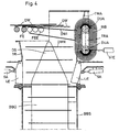
- this cylindrical brush roller BW occurs in the embodiment according to FIG. 1 also rotating in both directions of rotation brush belt BB whose both DUA rotary transfer axes on a swiveling TRA bracket are arranged, its storage and swivel drive training this Correspond elements in the training of FIG. 2.
Landscapes
- Engineering & Computer Science (AREA)
- Mechanical Engineering (AREA)
- Winding, Rewinding, Material Storage Devices (AREA)
- Coiling Of Filamentary Materials In General (AREA)
Abstract
Description
- Fig. 1
- die Ansicht eines Vertikalschnitts durch eine Vorrichtung nach dem Stande der Technik,
- Fig. 2
- die Ansicht eines Vertikalschnitts durch eine Vorrichtung nach der Erfindung,
- Fig. 3
- die Ansicht eines Vertikalschnitts entsprechend Fig. 2 durch eine andere Ausbildungsform der Vorrichtung und
- Fig. 4
- eine Ansicht entsprechend Fig. 2 durch eine weitere, andere Ausbildungsform der Vorrichtung.
- FE
- Fördereinrichtung
- FEE
- Ende der Fördereinrichtung
- DW
- Walzdrahtwindungen
- DW1
- (erste) Walzdrahtwindung
- BDD
- Bundbildedorn
- TR
- Trichter
- LE
- Leitelement
- SA
- Stellantrieb
- DS
- Dornspitze
- BBS
- Bundbildeschacht
- TWA
- (verlängerte) Wand des Trichters TR
- TRA
- Träger
- STE
- Stellelement
- BE
- Bürstenelement
- BO
- Borsten
- DWH
- Walzdrahtwindung (in horizontaler Position)
- BW
- Bürstenwalze
- DA
- Drehachse (der Bürstenwalze)
- DUA
- Drehumführungsachse
- BB
- Bürstenband
- Pfeil
- S
- Pfeil
- KW
- Doppelpfeil
- D
Claims (4)
- Vorrichtung zur Beeinflussung der Abwurf-Fallposition von Walzdrahtwindungen (DW), die etwa horizontal auf einer Fördereinrichtung (FE) aufliegend, in einen unterhalb des Endes (FEE) der Fördereinrichtung (FE) und, in Transportrichtung hinter diesem vertikal aufstehenden Bundbildeschacht (BBS) abgeworfen werden,
gekennzeichnet durch
eine mit Abstand von dem Ende (FEE) der Fördereinrichtung (FE), diesem gegenüberliegend und unterhalb der Einwurföffnung des Bundbildeschachtes (BBS), im Fallbereich der heran transportierten Walzdrahtwindungen (DW) angeordnete, den Außenumfang der Walzdrahtwindungen beaufschlagende Reibungsbremse. - Vorrichtung nach Anspruch 1,
dadurch gekennzeichnet, dass die Reibungsbremse aus einem, entgegen der Transportrichtung der Fördereinrichtung (FE) gegen die Walzdrahtwindungen (WW) und von diesen weg verschieb- oder verschwenkbaren Bürstenelement (BE) besteht. - Vorrichtung nach Anspruch 2,
dadurch gekennzeichnet, dass das Bürstenelement (BE) aus einer rotierend antreibbaren Bürstenwalze (BW) besteht. - Vorrichtung nach Anspruch 2,
dadurch gekennzeichnet, dass das Bürstenelement (BE) aus einem rotierend antreibbaren Bürstenband (BB) besteht.
Applications Claiming Priority (2)
| Application Number | Priority Date | Filing Date | Title |
|---|---|---|---|
| DE10052731 | 2000-10-25 | ||
| DE10052731A DE10052731A1 (de) | 2000-10-25 | 2000-10-25 | Vorrichtung zur Beeinflussung der Abwurf-Fallposition von in einen Bundbildeschacht abgeworfenen Walzdrahtwindungen |
Publications (2)
| Publication Number | Publication Date |
|---|---|
| EP1201327A2 true EP1201327A2 (de) | 2002-05-02 |
| EP1201327A3 EP1201327A3 (de) | 2002-12-04 |
Family
ID=7660911
Family Applications (1)
| Application Number | Title | Priority Date | Filing Date |
|---|---|---|---|
| EP01123190A Withdrawn EP1201327A3 (de) | 2000-10-25 | 2001-09-28 | Vorrichtung zur Beeinflussung der Abwurf-Fallposition von in einen Bundbildeschacht abgeworfenen Walzdrahtwindungen |
Country Status (3)
| Country | Link |
|---|---|
| US (1) | US6726138B2 (de) |
| EP (1) | EP1201327A3 (de) |
| DE (1) | DE10052731A1 (de) |
Cited By (1)
| Publication number | Priority date | Publication date | Assignee | Title |
|---|---|---|---|---|
| EP3260212A1 (de) * | 2016-06-20 | 2017-12-27 | Sund Birsta AB | Spulenformmaschine |
Families Citing this family (4)
| Publication number | Priority date | Publication date | Assignee | Title |
|---|---|---|---|---|
| DE102007029811B3 (de) * | 2007-06-27 | 2008-07-24 | Sms Meer Gmbh | Drehrohrhaspel zum Ablegen von gewalztem Draht |
| GB2501752B (en) * | 2012-05-04 | 2015-01-28 | Siemens Vai Metals Tech Gmbh | Coil forming device |
| US9162269B2 (en) | 2012-11-29 | 2015-10-20 | Primetals Technologies USA LLC | Coil forming apparatus and method |
| US20220219215A1 (en) | 2021-01-11 | 2022-07-14 | Primetals Technologies USA LLC | Automated rod coil cutting station |
Family Cites Families (10)
| Publication number | Priority date | Publication date | Assignee | Title |
|---|---|---|---|---|
| DE1752519B1 (de) * | 1968-06-08 | 1971-04-15 | Schloemann Ag | Einrichtung zum kuehlen von walzdraht |
| JPS5380357A (en) * | 1976-12-27 | 1978-07-15 | Nippon Steel Corp | Wire rod convergent device at wire rod rolling |
| JP2810113B2 (ja) * | 1989-05-29 | 1998-10-15 | 新日本製鐵株式会社 | 金属薄帯の搬送及び巻取り装置 |
| FR2658100B1 (fr) * | 1990-02-12 | 1992-04-30 | Unimetall Sa | Procede et dispositif de formation de bobines de fil metallique. |
| US5273231A (en) * | 1992-08-03 | 1993-12-28 | Morgan Construction Company | Loop distributor for reforming station |
| US5779174A (en) * | 1996-04-02 | 1998-07-14 | Morgan Construction Company | Mounting arrangement for loop distributor in a reforming chamber |
| DE19620578A1 (de) * | 1996-05-22 | 1997-11-27 | Thaelmann Schwermaschbau Veb | Vorrichtung zum positionierten Ablegen von Walzdrahtwindungen zu einem Drahtbund |
| DE19811649A1 (de) * | 1998-03-18 | 1999-09-23 | Schloemann Siemag Ag | Vorrichtung zur Führung und Querverschiebung von Walzdrahtwindungen |
| DE19835962A1 (de) * | 1998-08-08 | 2000-02-17 | Schloemann Siemag Ag | Verfahren und Vorrichtung zum Minimieren der Bundhöhe von Draht in einer Bundbildekammer |
| US6402074B1 (en) * | 1999-12-23 | 2002-06-11 | Morgan Construction Company | Apparatus for transferring rings from an inclined laying head onto a cooling conveyor |
-
2000
- 2000-10-25 DE DE10052731A patent/DE10052731A1/de not_active Withdrawn
-
2001
- 2001-09-28 EP EP01123190A patent/EP1201327A3/de not_active Withdrawn
- 2001-10-23 US US10/057,358 patent/US6726138B2/en not_active Expired - Fee Related
Cited By (2)
| Publication number | Priority date | Publication date | Assignee | Title |
|---|---|---|---|---|
| EP3260212A1 (de) * | 2016-06-20 | 2017-12-27 | Sund Birsta AB | Spulenformmaschine |
| WO2017220288A1 (en) * | 2016-06-20 | 2017-12-28 | Sund Birsta Ab | Coil-forming machine |
Also Published As
| Publication number | Publication date |
|---|---|
| US6726138B2 (en) | 2004-04-27 |
| EP1201327A3 (de) | 2002-12-04 |
| DE10052731A1 (de) | 2002-05-02 |
| US20020063138A1 (en) | 2002-05-30 |
Similar Documents
| Publication | Publication Date | Title |
|---|---|---|
| DE1031252B (de) | Vertikalhaspel | |
| EP0692180A1 (de) | Steuereinrichtung wenigstens eines Einzugsfingers eines Umlaufförderers | |
| DE3602574A1 (de) | Kreuzspulen herstellende maschine mit fahrbarem bedienungsaggregat | |
| CH668411A5 (de) | Vorrichtung zum speichern von in schuppenformation anfallenden druckprodukten. | |
| DE4131527A1 (de) | Caddy fuer den voneinander unabhaengigen einzeltransport von kopsen und kopshuelsen in einem transportsystem einer textilmaschine | |
| DE10052731A1 (de) | Vorrichtung zur Beeinflussung der Abwurf-Fallposition von in einen Bundbildeschacht abgeworfenen Walzdrahtwindungen | |
| DE3203223C2 (de) | ||
| EP3552993A1 (de) | Vereinzelungsmaschine | |
| DE3002026A1 (de) | Windungsleger zum ablegen von duennem, langgestrecktem gut | |
| EP0607891B1 (de) | Vorrichtung zum Krumpfen, Recken, Trocknen, Appretieren, Färben, Zuführen od. dgl. von laufendem Textilgut, wie Bändern, Fäden od. dgl. | |
| DE2644500C3 (de) | Vorrichtung zum Zuführen von Kartuschhülsen o.a. einendig geschlossenen, hohlen Werkstücken, in einer bestimmten Ausrichtung | |
| DE2624169B2 (de) | Vorrichtung und verfahren zum kontinuierlichen aufwickeln eines drahtes | |
| DE19835962A1 (de) | Verfahren und Vorrichtung zum Minimieren der Bundhöhe von Draht in einer Bundbildekammer | |
| CH636538A5 (de) | Vorrichtung zum schaelen von koernigem gut. | |
| EP0943378A2 (de) | Vorrichtung zur Führung und Querverschiebung von Walzdrahtwindungen | |
| DE19704421B4 (de) | Vorrichtung zur Bildung von Bunden aus Walzdrahtschlingen | |
| EP0841278B1 (de) | Spulenwechsel- und Transporteinrichtung | |
| DE4240663C1 (de) | Spulenhalter für Garnspulen | |
| EP1590284B1 (de) | Einrichtung zur übergabe von druckprodukten mit einer schaufelradanordnung | |
| EP0768126B1 (de) | Verfahren und Vorrichtung zur Minimierung der Höhe von Drahtbunden | |
| DE2849724A1 (de) | Vorrichtung zum ausrichten von flaschen | |
| CH679481A5 (de) | ||
| EP0903308A1 (de) | Zellenrad zur Uebergabe von Gegenständen von einem ersten Fördermittel an ein zweites Fördermittel | |
| DE10151103C2 (de) | Fasswickelvorrichtung | |
| DE3144241C2 (de) | Vorrichtung zum Ausrichten und Magazinieren von elastischen, ringförmigen Körpern |
Legal Events
| Date | Code | Title | Description |
|---|---|---|---|
| PUAI | Public reference made under article 153(3) epc to a published international application that has entered the european phase |
Free format text: ORIGINAL CODE: 0009012 |
|
| 17P | Request for examination filed |
Effective date: 20010928 |
|
| AK | Designated contracting states |
Kind code of ref document: A2 Designated state(s): AT BE CH CY DE DK ES FI FR GB GR IE IT LI LU MC NL PT SE TR |
|
| AX | Request for extension of the european patent |
Free format text: AL;LT;LV;MK;RO;SI |
|
| PUAL | Search report despatched |
Free format text: ORIGINAL CODE: 0009013 |
|
| AK | Designated contracting states |
Kind code of ref document: A3 Designated state(s): AT BE CH CY DE DK ES FI FR GB GR IE IT LI LU MC NL PT SE TR |
|
| AX | Request for extension of the european patent |
Free format text: AL;LT;LV;MK;RO;SI |
|
| AKX | Designation fees paid |
Designated state(s): AT BE CH CY DE DK ES FI FR GB GR IE IT LI LU MC NL PT SE TR |
|
| 17Q | First examination report despatched |
Effective date: 20041028 |
|
| STAA | Information on the status of an ep patent application or granted ep patent |
Free format text: STATUS: THE APPLICATION IS DEEMED TO BE WITHDRAWN |
|
| 18D | Application deemed to be withdrawn |
Effective date: 20050308 |