EP1200653B1 - Meso- und nanoröhren - Google Patents
Meso- und nanoröhren Download PDFInfo
- Publication number
- EP1200653B1 EP1200653B1 EP00949327A EP00949327A EP1200653B1 EP 1200653 B1 EP1200653 B1 EP 1200653B1 EP 00949327 A EP00949327 A EP 00949327A EP 00949327 A EP00949327 A EP 00949327A EP 1200653 B1 EP1200653 B1 EP 1200653B1
- Authority
- EP
- European Patent Office
- Prior art keywords
- hollow fibres
- hollow
- fibres according
- hollow fibers
- fibers
- Prior art date
- Legal status (The legal status is an assumption and is not a legal conclusion. Google has not performed a legal analysis and makes no representation as to the accuracy of the status listed.)
- Expired - Lifetime
Links
- 239000002071 nanotube Substances 0.000 title abstract description 4
- 239000000463 material Substances 0.000 claims abstract description 57
- 238000000034 method Methods 0.000 claims abstract description 31
- 238000004519 manufacturing process Methods 0.000 claims abstract description 20
- 238000000576 coating method Methods 0.000 claims abstract description 17
- 239000011248 coating agent Substances 0.000 claims abstract description 16
- 238000000926 separation method Methods 0.000 claims abstract description 14
- 238000005516 engineering process Methods 0.000 claims abstract description 8
- 238000004377 microelectronic Methods 0.000 claims abstract description 3
- 239000000835 fiber Substances 0.000 claims description 55
- 229920000642 polymer Polymers 0.000 claims description 55
- 229910052751 metal Inorganic materials 0.000 claims description 42
- 239000002184 metal Substances 0.000 claims description 42
- -1 poly(p-xylylene) Polymers 0.000 claims description 36
- 229920000747 poly(lactic acid) Polymers 0.000 claims description 29
- 229920000052 poly(p-xylylene) Polymers 0.000 claims description 22
- 238000001523 electrospinning Methods 0.000 claims description 18
- 239000011521 glass Substances 0.000 claims description 17
- 239000007789 gas Substances 0.000 claims description 16
- 150000002739 metals Chemical class 0.000 claims description 15
- 239000000919 ceramic Substances 0.000 claims description 14
- 150000002484 inorganic compounds Chemical class 0.000 claims description 12
- 229910010272 inorganic material Inorganic materials 0.000 claims description 12
- 239000010410 layer Substances 0.000 claims description 10
- OKTJSMMVPCPJKN-UHFFFAOYSA-N Carbon Chemical compound [C] OKTJSMMVPCPJKN-UHFFFAOYSA-N 0.000 claims description 8
- 230000015556 catabolic process Effects 0.000 claims description 8
- 238000006731 degradation reaction Methods 0.000 claims description 8
- 239000002904 solvent Substances 0.000 claims description 7
- 239000004642 Polyimide Substances 0.000 claims description 6
- 229920001721 polyimide Polymers 0.000 claims description 6
- VYPSYNLAJGMNEJ-UHFFFAOYSA-N Silicium dioxide Chemical compound O=[Si]=O VYPSYNLAJGMNEJ-UHFFFAOYSA-N 0.000 claims description 5
- PNEYBMLMFCGWSK-UHFFFAOYSA-N aluminium oxide Inorganic materials [O-2].[O-2].[O-2].[Al+3].[Al+3] PNEYBMLMFCGWSK-UHFFFAOYSA-N 0.000 claims description 5
- 239000002131 composite material Substances 0.000 claims description 5
- 238000000502 dialysis Methods 0.000 claims description 4
- 239000011229 interlayer Substances 0.000 claims description 4
- 238000003860 storage Methods 0.000 claims description 4
- 239000000956 alloy Substances 0.000 claims description 3
- 229910045601 alloy Inorganic materials 0.000 claims description 3
- 230000003197 catalytic effect Effects 0.000 claims description 3
- 239000003989 dielectric material Substances 0.000 claims description 3
- 239000000446 fuel Substances 0.000 claims description 3
- 239000002241 glass-ceramic Substances 0.000 claims description 3
- 239000012212 insulator Substances 0.000 claims description 3
- 239000007788 liquid Substances 0.000 claims description 3
- 210000004072 lung Anatomy 0.000 claims description 3
- 239000000203 mixture Substances 0.000 claims description 3
- RVTZCBVAJQQJTK-UHFFFAOYSA-N oxygen(2-);zirconium(4+) Chemical class [O-2].[O-2].[Zr+4] RVTZCBVAJQQJTK-UHFFFAOYSA-N 0.000 claims description 3
- 239000002245 particle Substances 0.000 claims description 3
- 230000000737 periodic effect Effects 0.000 claims description 3
- 102000004169 proteins and genes Human genes 0.000 claims description 3
- 108090000623 proteins and genes Proteins 0.000 claims description 3
- 229910001928 zirconium oxide Inorganic materials 0.000 claims description 3
- 102000004190 Enzymes Human genes 0.000 claims description 2
- 108090000790 Enzymes Proteins 0.000 claims description 2
- 229960000074 biopharmaceutical Drugs 0.000 claims description 2
- 239000003990 capacitor Substances 0.000 claims description 2
- 229910052799 carbon Inorganic materials 0.000 claims description 2
- 229910002090 carbon oxide Inorganic materials 0.000 claims description 2
- 238000010276 construction Methods 0.000 claims description 2
- 238000013270 controlled release Methods 0.000 claims description 2
- 238000012377 drug delivery Methods 0.000 claims description 2
- 238000003487 electrochemical reaction Methods 0.000 claims description 2
- 238000000605 extraction Methods 0.000 claims description 2
- 239000000945 filler Substances 0.000 claims description 2
- 239000002207 metabolite Substances 0.000 claims description 2
- 229910044991 metal oxide Inorganic materials 0.000 claims description 2
- 150000004706 metal oxides Chemical class 0.000 claims description 2
- 230000005855 radiation Effects 0.000 claims description 2
- 230000002787 reinforcement Effects 0.000 claims description 2
- 238000004621 scanning probe microscopy Methods 0.000 claims description 2
- HBMJWWWQQXIZIP-UHFFFAOYSA-N silicon carbide Chemical compound [Si+]#[C-] HBMJWWWQQXIZIP-UHFFFAOYSA-N 0.000 claims description 2
- 229910010271 silicon carbide Inorganic materials 0.000 claims description 2
- 239000000725 suspension Substances 0.000 claims description 2
- KKEYFWRCBNTPAC-UHFFFAOYSA-L terephthalate(2-) Chemical compound [O-]C(=O)C1=CC=C(C([O-])=O)C=C1 KKEYFWRCBNTPAC-UHFFFAOYSA-L 0.000 claims description 2
- 238000002604 ultrasonography Methods 0.000 claims description 2
- PPBRXRYQALVLMV-UHFFFAOYSA-N Styrene Chemical compound C=CC1=CC=CC=C1 PPBRXRYQALVLMV-UHFFFAOYSA-N 0.000 claims 4
- 229920001296 polysiloxane Polymers 0.000 claims 4
- VXNZUUAINFGPBY-UHFFFAOYSA-N 1-Butene Chemical compound CCC=C VXNZUUAINFGPBY-UHFFFAOYSA-N 0.000 claims 2
- KAKZBPTYRLMSJV-UHFFFAOYSA-N Butadiene Chemical compound C=CC=C KAKZBPTYRLMSJV-UHFFFAOYSA-N 0.000 claims 2
- 102000008186 Collagen Human genes 0.000 claims 2
- 108010035532 Collagen Proteins 0.000 claims 2
- 229920001634 Copolyester Polymers 0.000 claims 2
- VGGSQFUCUMXWEO-UHFFFAOYSA-N Ethene Chemical compound C=C VGGSQFUCUMXWEO-UHFFFAOYSA-N 0.000 claims 2
- 239000004952 Polyamide Substances 0.000 claims 2
- 239000005062 Polybutadiene Substances 0.000 claims 2
- 229920000265 Polyparaphenylene Polymers 0.000 claims 2
- 229920000615 alginic acid Polymers 0.000 claims 2
- 235000010443 alginic acid Nutrition 0.000 claims 2
- 125000003118 aryl group Chemical group 0.000 claims 2
- IAQRGUVFOMOMEM-UHFFFAOYSA-N but-2-ene Chemical compound CC=CC IAQRGUVFOMOMEM-UHFFFAOYSA-N 0.000 claims 2
- WERYXYBDKMZEQL-UHFFFAOYSA-N butane-1,4-diol Chemical compound OCCCCO WERYXYBDKMZEQL-UHFFFAOYSA-N 0.000 claims 2
- 229920002678 cellulose Polymers 0.000 claims 2
- 239000001913 cellulose Substances 0.000 claims 2
- 229920001436 collagen Polymers 0.000 claims 2
- KORSJDCBLAPZEQ-UHFFFAOYSA-N dicyclohexylmethane-4,4'-diisocyanate Chemical compound C1CC(N=C=O)CCC1CC1CCC(N=C=O)CC1 KORSJDCBLAPZEQ-UHFFFAOYSA-N 0.000 claims 2
- 229920000191 poly(N-vinyl pyrrolidone) Polymers 0.000 claims 2
- 229920001084 poly(chloroprene) Polymers 0.000 claims 2
- 229920001643 poly(ether ketone) Polymers 0.000 claims 2
- 229920003214 poly(methacrylonitrile) Polymers 0.000 claims 2
- 229920003229 poly(methyl methacrylate) Polymers 0.000 claims 2
- 229920000548 poly(silane) polymer Polymers 0.000 claims 2
- 229920002492 poly(sulfone) Polymers 0.000 claims 2
- 229920002401 polyacrylamide Polymers 0.000 claims 2
- 229920000058 polyacrylate Polymers 0.000 claims 2
- 229920002239 polyacrylonitrile Polymers 0.000 claims 2
- 229920002647 polyamide Polymers 0.000 claims 2
- 229920002480 polybenzimidazole Polymers 0.000 claims 2
- 229920002857 polybutadiene Polymers 0.000 claims 2
- 229920001707 polybutylene terephthalate Polymers 0.000 claims 2
- 229920000515 polycarbonate Polymers 0.000 claims 2
- 239000004417 polycarbonate Substances 0.000 claims 2
- 238000006068 polycondensation reaction Methods 0.000 claims 2
- 229920000728 polyester Polymers 0.000 claims 2
- 229920006149 polyester-amide block copolymer Polymers 0.000 claims 2
- 229920000570 polyether Polymers 0.000 claims 2
- 229920000139 polyethylene terephthalate Polymers 0.000 claims 2
- 239000005020 polyethylene terephthalate Substances 0.000 claims 2
- 229920002338 polyhydroxyethylmethacrylate Polymers 0.000 claims 2
- 239000004926 polymethyl methacrylate Substances 0.000 claims 2
- 229920000098 polyolefin Polymers 0.000 claims 2
- 229920001021 polysulfide Polymers 0.000 claims 2
- 239000005077 polysulfide Substances 0.000 claims 2
- 150000008117 polysulfides Polymers 0.000 claims 2
- 229920001343 polytetrafluoroethylene Polymers 0.000 claims 2
- 229920002635 polyurethane Polymers 0.000 claims 2
- 239000004814 polyurethane Substances 0.000 claims 2
- 229920002689 polyvinyl acetate Polymers 0.000 claims 2
- 239000011118 polyvinyl acetate Substances 0.000 claims 2
- 229910052814 silicon oxide Inorganic materials 0.000 claims 2
- 229940008841 1,6-hexamethylene diisocyanate Drugs 0.000 claims 1
- AGBXYHCHUYARJY-UHFFFAOYSA-N 2-phenylethenesulfonic acid Chemical compound OS(=O)(=O)C=CC1=CC=CC=C1 AGBXYHCHUYARJY-UHFFFAOYSA-N 0.000 claims 1
- NLHHRLWOUZZQLW-UHFFFAOYSA-N Acrylonitrile Chemical compound C=CC#N NLHHRLWOUZZQLW-UHFFFAOYSA-N 0.000 claims 1
- IMROMDMJAWUWLK-UHFFFAOYSA-N Ethenol Chemical compound OC=C IMROMDMJAWUWLK-UHFFFAOYSA-N 0.000 claims 1
- 239000005977 Ethylene Substances 0.000 claims 1
- PIICEJLVQHRZGT-UHFFFAOYSA-N Ethylenediamine Chemical compound NCCN PIICEJLVQHRZGT-UHFFFAOYSA-N 0.000 claims 1
- 239000005057 Hexamethylene diisocyanate Substances 0.000 claims 1
- CERQOIWHTDAKMF-UHFFFAOYSA-M Methacrylate Chemical compound CC(=C)C([O-])=O CERQOIWHTDAKMF-UHFFFAOYSA-M 0.000 claims 1
- VVQNEPGJFQJSBK-UHFFFAOYSA-N Methyl methacrylate Chemical compound COC(=O)C(C)=C VVQNEPGJFQJSBK-UHFFFAOYSA-N 0.000 claims 1
- BZHJMEDXRYGGRV-UHFFFAOYSA-N Vinyl chloride Chemical compound ClC=C BZHJMEDXRYGGRV-UHFFFAOYSA-N 0.000 claims 1
- 238000005251 capillar electrophoresis Methods 0.000 claims 1
- 239000000470 constituent Substances 0.000 claims 1
- XNMQEEKYCVKGBD-UHFFFAOYSA-N dimethylacetylene Natural products CC#CC XNMQEEKYCVKGBD-UHFFFAOYSA-N 0.000 claims 1
- RRAMGCGOFNQTLD-UHFFFAOYSA-N hexamethylene diisocyanate Chemical compound O=C=NCCCCCCN=C=O RRAMGCGOFNQTLD-UHFFFAOYSA-N 0.000 claims 1
- 239000000178 monomer Substances 0.000 claims 1
- 239000012510 hollow fiber Substances 0.000 abstract description 88
- 238000006555 catalytic reaction Methods 0.000 abstract description 3
- YMWUJEATGCHHMB-UHFFFAOYSA-N Dichloromethane Chemical compound ClCCl YMWUJEATGCHHMB-UHFFFAOYSA-N 0.000 description 24
- HTZCNXWZYVXIMZ-UHFFFAOYSA-M benzyl(triethyl)azanium;chloride Chemical compound [Cl-].CC[N+](CC)(CC)CC1=CC=CC=C1 HTZCNXWZYVXIMZ-UHFFFAOYSA-M 0.000 description 10
- 238000001878 scanning electron micrograph Methods 0.000 description 8
- 229910052782 aluminium Inorganic materials 0.000 description 7
- XAGFODPZIPBFFR-UHFFFAOYSA-N aluminium Chemical compound [Al] XAGFODPZIPBFFR-UHFFFAOYSA-N 0.000 description 7
- 239000000523 sample Substances 0.000 description 7
- 238000004626 scanning electron microscopy Methods 0.000 description 7
- 230000015572 biosynthetic process Effects 0.000 description 6
- PCHJSUWPFVWCPO-UHFFFAOYSA-N gold Chemical compound [Au] PCHJSUWPFVWCPO-UHFFFAOYSA-N 0.000 description 6
- 229910052737 gold Inorganic materials 0.000 description 6
- 239000010931 gold Substances 0.000 description 6
- 239000000654 additive Substances 0.000 description 5
- 230000000996 additive effect Effects 0.000 description 5
- 238000007740 vapor deposition Methods 0.000 description 5
- PXHVJJICTQNCMI-UHFFFAOYSA-N Nickel Chemical compound [Ni] PXHVJJICTQNCMI-UHFFFAOYSA-N 0.000 description 4
- KDLHZDBZIXYQEI-UHFFFAOYSA-N Palladium Chemical compound [Pd] KDLHZDBZIXYQEI-UHFFFAOYSA-N 0.000 description 4
- 210000004027 cell Anatomy 0.000 description 4
- 239000004744 fabric Substances 0.000 description 4
- BASFCYQUMIYNBI-UHFFFAOYSA-N platinum Chemical compound [Pt] BASFCYQUMIYNBI-UHFFFAOYSA-N 0.000 description 4
- LIVNPJMFVYWSIS-UHFFFAOYSA-N silicon monoxide Chemical compound [Si-]#[O+] LIVNPJMFVYWSIS-UHFFFAOYSA-N 0.000 description 4
- 239000000126 substance Substances 0.000 description 4
- XLYOFNOQVPJJNP-UHFFFAOYSA-N water Substances O XLYOFNOQVPJJNP-UHFFFAOYSA-N 0.000 description 4
- 239000002253 acid Substances 0.000 description 3
- 238000006243 chemical reaction Methods 0.000 description 3
- 238000000151 deposition Methods 0.000 description 3
- 238000010035 extrusion spinning Methods 0.000 description 3
- 125000000524 functional group Chemical group 0.000 description 3
- 239000012528 membrane Substances 0.000 description 3
- 239000001301 oxygen Substances 0.000 description 3
- 229910052760 oxygen Inorganic materials 0.000 description 3
- 238000002360 preparation method Methods 0.000 description 3
- OOLUVSIJOMLOCB-UHFFFAOYSA-N 1633-22-3 Chemical compound C1CC(C=C2)=CC=C2CCC2=CC=C1C=C2 OOLUVSIJOMLOCB-UHFFFAOYSA-N 0.000 description 2
- XMWRBQBLMFGWIX-UHFFFAOYSA-N C60 fullerene Chemical compound C12=C3C(C4=C56)=C7C8=C5C5=C9C%10=C6C6=C4C1=C1C4=C6C6=C%10C%10=C9C9=C%11C5=C8C5=C8C7=C3C3=C7C2=C1C1=C2C4=C6C4=C%10C6=C9C9=C%11C5=C5C8=C3C3=C7C1=C1C2=C4C6=C2C9=C5C3=C12 XMWRBQBLMFGWIX-UHFFFAOYSA-N 0.000 description 2
- 238000004566 IR spectroscopy Methods 0.000 description 2
- 239000004372 Polyvinyl alcohol Substances 0.000 description 2
- JUJWROOIHBZHMG-UHFFFAOYSA-N Pyridine Chemical compound C1=CC=NC=C1 JUJWROOIHBZHMG-UHFFFAOYSA-N 0.000 description 2
- QVGXLLKOCUKJST-UHFFFAOYSA-N atomic oxygen Chemical compound [O] QVGXLLKOCUKJST-UHFFFAOYSA-N 0.000 description 2
- 238000009530 blood pressure measurement Methods 0.000 description 2
- 238000000354 decomposition reaction Methods 0.000 description 2
- 230000008021 deposition Effects 0.000 description 2
- 150000002148 esters Chemical group 0.000 description 2
- 238000001914 filtration Methods 0.000 description 2
- 229910003472 fullerene Inorganic materials 0.000 description 2
- 239000003365 glass fiber Substances 0.000 description 2
- 229910002804 graphite Inorganic materials 0.000 description 2
- 239000010439 graphite Substances 0.000 description 2
- NOESYZHRGYRDHS-UHFFFAOYSA-N insulin Chemical compound N1C(=O)C(NC(=O)C(CCC(N)=O)NC(=O)C(CCC(O)=O)NC(=O)C(C(C)C)NC(=O)C(NC(=O)CN)C(C)CC)CSSCC(C(NC(CO)C(=O)NC(CC(C)C)C(=O)NC(CC=2C=CC(O)=CC=2)C(=O)NC(CCC(N)=O)C(=O)NC(CC(C)C)C(=O)NC(CCC(O)=O)C(=O)NC(CC(N)=O)C(=O)NC(CC=2C=CC(O)=CC=2)C(=O)NC(CSSCC(NC(=O)C(C(C)C)NC(=O)C(CC(C)C)NC(=O)C(CC=2C=CC(O)=CC=2)NC(=O)C(CC(C)C)NC(=O)C(C)NC(=O)C(CCC(O)=O)NC(=O)C(C(C)C)NC(=O)C(CC(C)C)NC(=O)C(CC=2NC=NC=2)NC(=O)C(CO)NC(=O)CNC2=O)C(=O)NCC(=O)NC(CCC(O)=O)C(=O)NC(CCCNC(N)=N)C(=O)NCC(=O)NC(CC=3C=CC=CC=3)C(=O)NC(CC=3C=CC=CC=3)C(=O)NC(CC=3C=CC(O)=CC=3)C(=O)NC(C(C)O)C(=O)N3C(CCC3)C(=O)NC(CCCCN)C(=O)NC(C)C(O)=O)C(=O)NC(CC(N)=O)C(O)=O)=O)NC(=O)C(C(C)CC)NC(=O)C(CO)NC(=O)C(C(C)O)NC(=O)C1CSSCC2NC(=O)C(CC(C)C)NC(=O)C(NC(=O)C(CCC(N)=O)NC(=O)C(CC(N)=O)NC(=O)C(NC(=O)C(N)CC=1C=CC=CC=1)C(C)C)CC1=CN=CN1 NOESYZHRGYRDHS-UHFFFAOYSA-N 0.000 description 2
- 229910052759 nickel Inorganic materials 0.000 description 2
- 239000003921 oil Substances 0.000 description 2
- 238000007254 oxidation reaction Methods 0.000 description 2
- 229910052763 palladium Inorganic materials 0.000 description 2
- 229910052697 platinum Inorganic materials 0.000 description 2
- 229920001432 poly(L-lactide) Polymers 0.000 description 2
- 229920002451 polyvinyl alcohol Polymers 0.000 description 2
- 238000000197 pyrolysis Methods 0.000 description 2
- 238000009987 spinning Methods 0.000 description 2
- 239000000758 substrate Substances 0.000 description 2
- 229910052582 BN Inorganic materials 0.000 description 1
- 241000894006 Bacteria Species 0.000 description 1
- PZNSFCLAULLKQX-UHFFFAOYSA-N Boron nitride Chemical compound N#B PZNSFCLAULLKQX-UHFFFAOYSA-N 0.000 description 1
- OYPRJOBELJOOCE-UHFFFAOYSA-N Calcium Chemical compound [Ca] OYPRJOBELJOOCE-UHFFFAOYSA-N 0.000 description 1
- 241001631457 Cannula Species 0.000 description 1
- KXDHJXZQYSOELW-UHFFFAOYSA-N Carbamic acid Chemical group NC(O)=O KXDHJXZQYSOELW-UHFFFAOYSA-N 0.000 description 1
- VYZAMTAEIAYCRO-UHFFFAOYSA-N Chromium Chemical compound [Cr] VYZAMTAEIAYCRO-UHFFFAOYSA-N 0.000 description 1
- UFHFLCQGNIYNRP-UHFFFAOYSA-N Hydrogen Chemical compound [H][H] UFHFLCQGNIYNRP-UHFFFAOYSA-N 0.000 description 1
- DGAQECJNVWCQMB-PUAWFVPOSA-M Ilexoside XXIX Chemical compound C[C@@H]1CC[C@@]2(CC[C@@]3(C(=CC[C@H]4[C@]3(CC[C@@H]5[C@@]4(CC[C@@H](C5(C)C)OS(=O)(=O)[O-])C)C)[C@@H]2[C@]1(C)O)C)C(=O)O[C@H]6[C@@H]([C@H]([C@@H]([C@H](O6)CO)O)O)O.[Na+] DGAQECJNVWCQMB-PUAWFVPOSA-M 0.000 description 1
- 102000004877 Insulin Human genes 0.000 description 1
- 108090001061 Insulin Proteins 0.000 description 1
- WHXSMMKQMYFTQS-UHFFFAOYSA-N Lithium Chemical compound [Li] WHXSMMKQMYFTQS-UHFFFAOYSA-N 0.000 description 1
- PWHULOQIROXLJO-UHFFFAOYSA-N Manganese Chemical compound [Mn] PWHULOQIROXLJO-UHFFFAOYSA-N 0.000 description 1
- ZLMJMSJWJFRBEC-UHFFFAOYSA-N Potassium Chemical compound [K] ZLMJMSJWJFRBEC-UHFFFAOYSA-N 0.000 description 1
- KJTLSVCANCCWHF-UHFFFAOYSA-N Ruthenium Chemical compound [Ru] KJTLSVCANCCWHF-UHFFFAOYSA-N 0.000 description 1
- BQCADISMDOOEFD-UHFFFAOYSA-N Silver Chemical compound [Ag] BQCADISMDOOEFD-UHFFFAOYSA-N 0.000 description 1
- RTAQQCXQSZGOHL-UHFFFAOYSA-N Titanium Chemical compound [Ti] RTAQQCXQSZGOHL-UHFFFAOYSA-N 0.000 description 1
- 241000700605 Viruses Species 0.000 description 1
- 238000000441 X-ray spectroscopy Methods 0.000 description 1
- 239000013543 active substance Substances 0.000 description 1
- 239000003905 agrochemical Substances 0.000 description 1
- 150000001336 alkenes Chemical class 0.000 description 1
- 150000001408 amides Chemical group 0.000 description 1
- 150000001412 amines Chemical group 0.000 description 1
- 238000004458 analytical method Methods 0.000 description 1
- 229940035674 anesthetics Drugs 0.000 description 1
- 239000003242 anti bacterial agent Substances 0.000 description 1
- 229940088710 antibiotic agent Drugs 0.000 description 1
- 239000002519 antifouling agent Substances 0.000 description 1
- 230000033228 biological regulation Effects 0.000 description 1
- 229910052791 calcium Inorganic materials 0.000 description 1
- 239000011575 calcium Substances 0.000 description 1
- 239000002041 carbon nanotube Substances 0.000 description 1
- 229910021393 carbon nanotube Inorganic materials 0.000 description 1
- 239000003054 catalyst Substances 0.000 description 1
- 210000000170 cell membrane Anatomy 0.000 description 1
- 229920002301 cellulose acetate Polymers 0.000 description 1
- 238000004587 chromatography analysis Methods 0.000 description 1
- 229910052804 chromium Inorganic materials 0.000 description 1
- 239000011651 chromium Substances 0.000 description 1
- 229910017052 cobalt Inorganic materials 0.000 description 1
- 239000010941 cobalt Substances 0.000 description 1
- GUTLYIVDDKVIGB-UHFFFAOYSA-N cobalt atom Chemical compound [Co] GUTLYIVDDKVIGB-UHFFFAOYSA-N 0.000 description 1
- 239000004020 conductor Substances 0.000 description 1
- 210000000805 cytoplasm Anatomy 0.000 description 1
- 230000001086 cytosolic effect Effects 0.000 description 1
- 238000010612 desalination reaction Methods 0.000 description 1
- 238000004090 dissolution Methods 0.000 description 1
- 239000003814 drug Substances 0.000 description 1
- 239000000975 dye Substances 0.000 description 1
- 230000005684 electric field Effects 0.000 description 1
- 238000010041 electrostatic spinning Methods 0.000 description 1
- 125000000816 ethylene group Chemical group [H]C([H])([*:1])C([H])([H])[*:2] 0.000 description 1
- 238000001704 evaporation Methods 0.000 description 1
- 230000008020 evaporation Effects 0.000 description 1
- 239000002657 fibrous material Substances 0.000 description 1
- 238000007306 functionalization reaction Methods 0.000 description 1
- 239000000417 fungicide Substances 0.000 description 1
- 239000003193 general anesthetic agent Substances 0.000 description 1
- 230000020169 heat generation Effects 0.000 description 1
- 239000004009 herbicide Substances 0.000 description 1
- 239000001257 hydrogen Substances 0.000 description 1
- 229910052739 hydrogen Inorganic materials 0.000 description 1
- 230000007062 hydrolysis Effects 0.000 description 1
- 238000006460 hydrolysis reaction Methods 0.000 description 1
- 238000001027 hydrothermal synthesis Methods 0.000 description 1
- 125000002887 hydroxy group Chemical group [H]O* 0.000 description 1
- 238000007654 immersion Methods 0.000 description 1
- 238000012844 infrared spectroscopy analysis Methods 0.000 description 1
- 238000002329 infrared spectrum Methods 0.000 description 1
- 229940125396 insulin Drugs 0.000 description 1
- 150000002500 ions Chemical class 0.000 description 1
- 238000003973 irrigation Methods 0.000 description 1
- 230000002262 irrigation Effects 0.000 description 1
- 229910052744 lithium Inorganic materials 0.000 description 1
- 229910052748 manganese Inorganic materials 0.000 description 1
- 239000011572 manganese Substances 0.000 description 1
- 230000002503 metabolic effect Effects 0.000 description 1
- 238000000386 microscopy Methods 0.000 description 1
- 238000004651 near-field scanning optical microscopy Methods 0.000 description 1
- 125000002560 nitrile group Chemical group 0.000 description 1
- JRZJOMJEPLMPRA-UHFFFAOYSA-N olefin Natural products CCCCCCCC=C JRZJOMJEPLMPRA-UHFFFAOYSA-N 0.000 description 1
- 150000002902 organometallic compounds Chemical class 0.000 description 1
- 230000003647 oxidation Effects 0.000 description 1
- 239000011148 porous material Substances 0.000 description 1
- 229910052700 potassium Inorganic materials 0.000 description 1
- 239000011591 potassium Substances 0.000 description 1
- 239000010970 precious metal Substances 0.000 description 1
- 238000000746 purification Methods 0.000 description 1
- UMJSCPRVCHMLSP-UHFFFAOYSA-N pyridine Natural products COC1=CC=CN=C1 UMJSCPRVCHMLSP-UHFFFAOYSA-N 0.000 description 1
- 125000004076 pyridyl group Chemical group 0.000 description 1
- 239000010453 quartz Substances 0.000 description 1
- 238000011084 recovery Methods 0.000 description 1
- 229910052703 rhodium Inorganic materials 0.000 description 1
- 239000010948 rhodium Substances 0.000 description 1
- MHOVAHRLVXNVSD-UHFFFAOYSA-N rhodium atom Chemical compound [Rh] MHOVAHRLVXNVSD-UHFFFAOYSA-N 0.000 description 1
- 229910052707 ruthenium Inorganic materials 0.000 description 1
- 238000007127 saponification reaction Methods 0.000 description 1
- 229910052710 silicon Inorganic materials 0.000 description 1
- 239000010703 silicon Substances 0.000 description 1
- 239000000377 silicon dioxide Substances 0.000 description 1
- 125000005373 siloxane group Chemical group [SiH2](O*)* 0.000 description 1
- 229910052709 silver Inorganic materials 0.000 description 1
- 239000004332 silver Substances 0.000 description 1
- 125000003808 silyl group Chemical group [H][Si]([H])([H])[*] 0.000 description 1
- 229910052708 sodium Inorganic materials 0.000 description 1
- 239000011734 sodium Substances 0.000 description 1
- 239000007858 starting material Substances 0.000 description 1
- 125000001174 sulfone group Chemical group 0.000 description 1
- 125000003375 sulfoxide group Chemical group 0.000 description 1
- 238000003786 synthesis reaction Methods 0.000 description 1
- 239000004753 textile Substances 0.000 description 1
- 150000003573 thiols Chemical group 0.000 description 1
- 210000001519 tissue Anatomy 0.000 description 1
- 229910052719 titanium Inorganic materials 0.000 description 1
- 239000010936 titanium Substances 0.000 description 1
- 238000012876 topography Methods 0.000 description 1
- WFKWXMTUELFFGS-UHFFFAOYSA-N tungsten Chemical compound [W] WFKWXMTUELFFGS-UHFFFAOYSA-N 0.000 description 1
- 229910052721 tungsten Inorganic materials 0.000 description 1
- 239000010937 tungsten Substances 0.000 description 1
- JOYRKODLDBILNP-UHFFFAOYSA-N urethane group Chemical group NC(=O)OCC JOYRKODLDBILNP-UHFFFAOYSA-N 0.000 description 1
- 229910052720 vanadium Inorganic materials 0.000 description 1
- GPPXJZIENCGNKB-UHFFFAOYSA-N vanadium Chemical compound [V]#[V] GPPXJZIENCGNKB-UHFFFAOYSA-N 0.000 description 1
Images






Classifications
-
- D—TEXTILES; PAPER
- D01—NATURAL OR MAN-MADE THREADS OR FIBRES; SPINNING
- D01D—MECHANICAL METHODS OR APPARATUS IN THE MANUFACTURE OF ARTIFICIAL FILAMENTS, THREADS, FIBRES, BRISTLES OR RIBBONS
- D01D5/00—Formation of filaments, threads, or the like
- D01D5/0007—Electro-spinning
- D01D5/0015—Electro-spinning characterised by the initial state of the material
- D01D5/003—Electro-spinning characterised by the initial state of the material the material being a polymer solution or dispersion
-
- B—PERFORMING OPERATIONS; TRANSPORTING
- B01—PHYSICAL OR CHEMICAL PROCESSES OR APPARATUS IN GENERAL
- B01D—SEPARATION
- B01D69/00—Semi-permeable membranes for separation processes or apparatus characterised by their form, structure or properties; Manufacturing processes specially adapted therefor
- B01D69/02—Semi-permeable membranes for separation processes or apparatus characterised by their form, structure or properties; Manufacturing processes specially adapted therefor characterised by their properties
-
- B—PERFORMING OPERATIONS; TRANSPORTING
- B01—PHYSICAL OR CHEMICAL PROCESSES OR APPARATUS IN GENERAL
- B01D—SEPARATION
- B01D69/00—Semi-permeable membranes for separation processes or apparatus characterised by their form, structure or properties; Manufacturing processes specially adapted therefor
- B01D69/08—Hollow fibre membranes
-
- B—PERFORMING OPERATIONS; TRANSPORTING
- B01—PHYSICAL OR CHEMICAL PROCESSES OR APPARATUS IN GENERAL
- B01D—SEPARATION
- B01D69/00—Semi-permeable membranes for separation processes or apparatus characterised by their form, structure or properties; Manufacturing processes specially adapted therefor
- B01D69/12—Composite membranes; Ultra-thin membranes
- B01D69/122—Separate manufacturing of ultra-thin membranes
-
- B—PERFORMING OPERATIONS; TRANSPORTING
- B01—PHYSICAL OR CHEMICAL PROCESSES OR APPARATUS IN GENERAL
- B01D—SEPARATION
- B01D71/00—Semi-permeable membranes for separation processes or apparatus characterised by the material; Manufacturing processes specially adapted therefor
- B01D71/02—Inorganic material
- B01D71/022—Metals
- B01D71/0221—Group 4 or 5 metals
-
- B—PERFORMING OPERATIONS; TRANSPORTING
- B01—PHYSICAL OR CHEMICAL PROCESSES OR APPARATUS IN GENERAL
- B01D—SEPARATION
- B01D71/00—Semi-permeable membranes for separation processes or apparatus characterised by the material; Manufacturing processes specially adapted therefor
- B01D71/02—Inorganic material
- B01D71/022—Metals
- B01D71/0223—Group 8, 9 or 10 metals
- B01D71/02231—Palladium
-
- B—PERFORMING OPERATIONS; TRANSPORTING
- B01—PHYSICAL OR CHEMICAL PROCESSES OR APPARATUS IN GENERAL
- B01D—SEPARATION
- B01D71/00—Semi-permeable membranes for separation processes or apparatus characterised by the material; Manufacturing processes specially adapted therefor
- B01D71/02—Inorganic material
- B01D71/022—Metals
- B01D71/0223—Group 8, 9 or 10 metals
- B01D71/02232—Nickel
-
- B—PERFORMING OPERATIONS; TRANSPORTING
- B01—PHYSICAL OR CHEMICAL PROCESSES OR APPARATUS IN GENERAL
- B01D—SEPARATION
- B01D71/00—Semi-permeable membranes for separation processes or apparatus characterised by the material; Manufacturing processes specially adapted therefor
- B01D71/02—Inorganic material
- B01D71/04—Glass
-
- B—PERFORMING OPERATIONS; TRANSPORTING
- B01—PHYSICAL OR CHEMICAL PROCESSES OR APPARATUS IN GENERAL
- B01D—SEPARATION
- B01D71/00—Semi-permeable membranes for separation processes or apparatus characterised by the material; Manufacturing processes specially adapted therefor
- B01D71/06—Organic material
- B01D71/58—Other polymers having nitrogen in the main chain, with or without oxygen or carbon only
- B01D71/62—Polycondensates having nitrogen-containing heterocyclic rings in the main chain
- B01D71/64—Polyimides; Polyamide-imides; Polyester-imides; Polyamide acids or similar polyimide precursors
-
- B—PERFORMING OPERATIONS; TRANSPORTING
- B01—PHYSICAL OR CHEMICAL PROCESSES OR APPARATUS IN GENERAL
- B01D—SEPARATION
- B01D71/00—Semi-permeable membranes for separation processes or apparatus characterised by the material; Manufacturing processes specially adapted therefor
- B01D71/06—Organic material
- B01D71/72—Macromolecular compounds obtained otherwise than by reactions only involving carbon-to-carbon unsaturated bonds, not provided for in a single one of the groups B01D71/46 - B01D71/70 and B01D71/701 - B01D71/702
-
- B—PERFORMING OPERATIONS; TRANSPORTING
- B01—PHYSICAL OR CHEMICAL PROCESSES OR APPARATUS IN GENERAL
- B01J—CHEMICAL OR PHYSICAL PROCESSES, e.g. CATALYSIS OR COLLOID CHEMISTRY; THEIR RELEVANT APPARATUS
- B01J35/00—Catalysts, in general, characterised by their form or physical properties
- B01J35/50—Catalysts, in general, characterised by their form or physical properties characterised by their shape or configuration
- B01J35/58—Fabrics or filaments
-
- D—TEXTILES; PAPER
- D01—NATURAL OR MAN-MADE THREADS OR FIBRES; SPINNING
- D01D—MECHANICAL METHODS OR APPARATUS IN THE MANUFACTURE OF ARTIFICIAL FILAMENTS, THREADS, FIBRES, BRISTLES OR RIBBONS
- D01D5/00—Formation of filaments, threads, or the like
- D01D5/24—Formation of filaments, threads, or the like with a hollow structure; Spinnerette packs therefor
-
- G—PHYSICS
- G01—MEASURING; TESTING
- G01N—INVESTIGATING OR ANALYSING MATERIALS BY DETERMINING THEIR CHEMICAL OR PHYSICAL PROPERTIES
- G01N27/00—Investigating or analysing materials by the use of electric, electrochemical, or magnetic means
- G01N27/26—Investigating or analysing materials by the use of electric, electrochemical, or magnetic means by investigating electrochemical variables; by using electrolysis or electrophoresis
- G01N27/416—Systems
- G01N27/447—Systems using electrophoresis
- G01N27/44704—Details; Accessories
-
- H—ELECTRICITY
- H01—ELECTRIC ELEMENTS
- H01M—PROCESSES OR MEANS, e.g. BATTERIES, FOR THE DIRECT CONVERSION OF CHEMICAL ENERGY INTO ELECTRICAL ENERGY
- H01M4/00—Electrodes
- H01M4/86—Inert electrodes with catalytic activity, e.g. for fuel cells
-
- H—ELECTRICITY
- H01—ELECTRIC ELEMENTS
- H01M—PROCESSES OR MEANS, e.g. BATTERIES, FOR THE DIRECT CONVERSION OF CHEMICAL ENERGY INTO ELECTRICAL ENERGY
- H01M8/00—Fuel cells; Manufacture thereof
- H01M8/02—Details
- H01M8/0289—Means for holding the electrolyte
-
- H—ELECTRICITY
- H01—ELECTRIC ELEMENTS
- H01M—PROCESSES OR MEANS, e.g. BATTERIES, FOR THE DIRECT CONVERSION OF CHEMICAL ENERGY INTO ELECTRICAL ENERGY
- H01M8/00—Fuel cells; Manufacture thereof
- H01M8/10—Fuel cells with solid electrolytes
- H01M8/12—Fuel cells with solid electrolytes operating at high temperature, e.g. with stabilised ZrO2 electrolyte
-
- H—ELECTRICITY
- H01—ELECTRIC ELEMENTS
- H01M—PROCESSES OR MEANS, e.g. BATTERIES, FOR THE DIRECT CONVERSION OF CHEMICAL ENERGY INTO ELECTRICAL ENERGY
- H01M8/00—Fuel cells; Manufacture thereof
- H01M8/10—Fuel cells with solid electrolytes
- H01M8/12—Fuel cells with solid electrolytes operating at high temperature, e.g. with stabilised ZrO2 electrolyte
- H01M8/124—Fuel cells with solid electrolytes operating at high temperature, e.g. with stabilised ZrO2 electrolyte characterised by the process of manufacturing or by the material of the electrolyte
- H01M8/1246—Fuel cells with solid electrolytes operating at high temperature, e.g. with stabilised ZrO2 electrolyte characterised by the process of manufacturing or by the material of the electrolyte the electrolyte consisting of oxides
-
- Y—GENERAL TAGGING OF NEW TECHNOLOGICAL DEVELOPMENTS; GENERAL TAGGING OF CROSS-SECTIONAL TECHNOLOGIES SPANNING OVER SEVERAL SECTIONS OF THE IPC; TECHNICAL SUBJECTS COVERED BY FORMER USPC CROSS-REFERENCE ART COLLECTIONS [XRACs] AND DIGESTS
- Y02—TECHNOLOGIES OR APPLICATIONS FOR MITIGATION OR ADAPTATION AGAINST CLIMATE CHANGE
- Y02E—REDUCTION OF GREENHOUSE GAS [GHG] EMISSIONS, RELATED TO ENERGY GENERATION, TRANSMISSION OR DISTRIBUTION
- Y02E60/00—Enabling technologies; Technologies with a potential or indirect contribution to GHG emissions mitigation
- Y02E60/30—Hydrogen technology
- Y02E60/50—Fuel cells
-
- Y—GENERAL TAGGING OF NEW TECHNOLOGICAL DEVELOPMENTS; GENERAL TAGGING OF CROSS-SECTIONAL TECHNOLOGIES SPANNING OVER SEVERAL SECTIONS OF THE IPC; TECHNICAL SUBJECTS COVERED BY FORMER USPC CROSS-REFERENCE ART COLLECTIONS [XRACs] AND DIGESTS
- Y02—TECHNOLOGIES OR APPLICATIONS FOR MITIGATION OR ADAPTATION AGAINST CLIMATE CHANGE
- Y02P—CLIMATE CHANGE MITIGATION TECHNOLOGIES IN THE PRODUCTION OR PROCESSING OF GOODS
- Y02P70/00—Climate change mitigation technologies in the production process for final industrial or consumer products
- Y02P70/50—Manufacturing or production processes characterised by the final manufactured product
-
- Y—GENERAL TAGGING OF NEW TECHNOLOGICAL DEVELOPMENTS; GENERAL TAGGING OF CROSS-SECTIONAL TECHNOLOGIES SPANNING OVER SEVERAL SECTIONS OF THE IPC; TECHNICAL SUBJECTS COVERED BY FORMER USPC CROSS-REFERENCE ART COLLECTIONS [XRACs] AND DIGESTS
- Y10—TECHNICAL SUBJECTS COVERED BY FORMER USPC
- Y10S—TECHNICAL SUBJECTS COVERED BY FORMER USPC CROSS-REFERENCE ART COLLECTIONS [XRACs] AND DIGESTS
- Y10S977/00—Nanotechnology
- Y10S977/70—Nanostructure
- Y10S977/734—Fullerenes, i.e. graphene-based structures, such as nanohorns, nanococoons, nanoscrolls or fullerene-like structures, e.g. WS2 or MoS2 chalcogenide nanotubes, planar C3N4, etc.
-
- Y—GENERAL TAGGING OF NEW TECHNOLOGICAL DEVELOPMENTS; GENERAL TAGGING OF CROSS-SECTIONAL TECHNOLOGIES SPANNING OVER SEVERAL SECTIONS OF THE IPC; TECHNICAL SUBJECTS COVERED BY FORMER USPC CROSS-REFERENCE ART COLLECTIONS [XRACs] AND DIGESTS
- Y10—TECHNICAL SUBJECTS COVERED BY FORMER USPC
- Y10S—TECHNICAL SUBJECTS COVERED BY FORMER USPC CROSS-REFERENCE ART COLLECTIONS [XRACs] AND DIGESTS
- Y10S977/00—Nanotechnology
- Y10S977/84—Manufacture, treatment, or detection of nanostructure
- Y10S977/849—Manufacture, treatment, or detection of nanostructure with scanning probe
- Y10S977/86—Scanning probe structure
- Y10S977/875—Scanning probe structure with tip detail
- Y10S977/876—Nanotube tip
-
- Y—GENERAL TAGGING OF NEW TECHNOLOGICAL DEVELOPMENTS; GENERAL TAGGING OF CROSS-SECTIONAL TECHNOLOGIES SPANNING OVER SEVERAL SECTIONS OF THE IPC; TECHNICAL SUBJECTS COVERED BY FORMER USPC CROSS-REFERENCE ART COLLECTIONS [XRACs] AND DIGESTS
- Y10—TECHNICAL SUBJECTS COVERED BY FORMER USPC
- Y10S—TECHNICAL SUBJECTS COVERED BY FORMER USPC CROSS-REFERENCE ART COLLECTIONS [XRACs] AND DIGESTS
- Y10S977/00—Nanotechnology
- Y10S977/84—Manufacture, treatment, or detection of nanostructure
- Y10S977/888—Shaping or removal of materials, e.g. etching
-
- Y—GENERAL TAGGING OF NEW TECHNOLOGICAL DEVELOPMENTS; GENERAL TAGGING OF CROSS-SECTIONAL TECHNOLOGIES SPANNING OVER SEVERAL SECTIONS OF THE IPC; TECHNICAL SUBJECTS COVERED BY FORMER USPC CROSS-REFERENCE ART COLLECTIONS [XRACs] AND DIGESTS
- Y10—TECHNICAL SUBJECTS COVERED BY FORMER USPC
- Y10T—TECHNICAL SUBJECTS COVERED BY FORMER US CLASSIFICATION
- Y10T428/00—Stock material or miscellaneous articles
- Y10T428/29—Coated or structually defined flake, particle, cell, strand, strand portion, rod, filament, macroscopic fiber or mass thereof
- Y10T428/2913—Rod, strand, filament or fiber
-
- Y—GENERAL TAGGING OF NEW TECHNOLOGICAL DEVELOPMENTS; GENERAL TAGGING OF CROSS-SECTIONAL TECHNOLOGIES SPANNING OVER SEVERAL SECTIONS OF THE IPC; TECHNICAL SUBJECTS COVERED BY FORMER USPC CROSS-REFERENCE ART COLLECTIONS [XRACs] AND DIGESTS
- Y10—TECHNICAL SUBJECTS COVERED BY FORMER USPC
- Y10T—TECHNICAL SUBJECTS COVERED BY FORMER US CLASSIFICATION
- Y10T428/00—Stock material or miscellaneous articles
- Y10T428/29—Coated or structually defined flake, particle, cell, strand, strand portion, rod, filament, macroscopic fiber or mass thereof
- Y10T428/2913—Rod, strand, filament or fiber
- Y10T428/2933—Coated or with bond, impregnation or core
- Y10T428/2935—Discontinuous or tubular or cellular core
-
- Y—GENERAL TAGGING OF NEW TECHNOLOGICAL DEVELOPMENTS; GENERAL TAGGING OF CROSS-SECTIONAL TECHNOLOGIES SPANNING OVER SEVERAL SECTIONS OF THE IPC; TECHNICAL SUBJECTS COVERED BY FORMER USPC CROSS-REFERENCE ART COLLECTIONS [XRACs] AND DIGESTS
- Y10—TECHNICAL SUBJECTS COVERED BY FORMER USPC
- Y10T—TECHNICAL SUBJECTS COVERED BY FORMER US CLASSIFICATION
- Y10T428/00—Stock material or miscellaneous articles
- Y10T428/29—Coated or structually defined flake, particle, cell, strand, strand portion, rod, filament, macroscopic fiber or mass thereof
- Y10T428/2913—Rod, strand, filament or fiber
- Y10T428/2973—Particular cross section
-
- Y—GENERAL TAGGING OF NEW TECHNOLOGICAL DEVELOPMENTS; GENERAL TAGGING OF CROSS-SECTIONAL TECHNOLOGIES SPANNING OVER SEVERAL SECTIONS OF THE IPC; TECHNICAL SUBJECTS COVERED BY FORMER USPC CROSS-REFERENCE ART COLLECTIONS [XRACs] AND DIGESTS
- Y10—TECHNICAL SUBJECTS COVERED BY FORMER USPC
- Y10T—TECHNICAL SUBJECTS COVERED BY FORMER US CLASSIFICATION
- Y10T428/00—Stock material or miscellaneous articles
- Y10T428/29—Coated or structually defined flake, particle, cell, strand, strand portion, rod, filament, macroscopic fiber or mass thereof
- Y10T428/2913—Rod, strand, filament or fiber
- Y10T428/2973—Particular cross section
- Y10T428/2975—Tubular or cellular
Definitions
- the invention relates to meso- and nanotubes, d. H. Tubes or hollow fibers with an inner diameter in the nanometer to micrometer range according to the preamble of claim 1, and a method for producing a first embodiment of these hollow fibers according to the preamble of claim 11 and a further method for producing a second embodiment of these hollow fibers according to the preamble of claim 12.
- Hollow fibers, meso- or nanotubes are generally called tubes with an inner diameter of less than 0.1 mm
- Tubes or hollow fibers with a small inner diameter are known and are used in particular for separation purposes z.
- the fiber material usually consists of polymers, which moreover can have pores, ie properties of semipermeable membranes.
- the hollow fibers used for separation purposes usually have a surface area of 100 cm 2 per cm 3 volume with an inner diameter of 75 .mu.m to 1 mm.
- hollow fibers Another application of hollow fibers is microelectronics.
- superconducting approximately 60 microns in diameter fibers are made of superconducting material by hollow fibers of polymers are filled with a mass which has superconducting properties after thermal degradation of the polymer ( JCW Cien, H. Rinsdorf et al., Adv. Mater., 2 (1990) p. 305 ).
- Small inner diameter tubing is typically made by extrusion spinning processes.
- extrusion spinning processes are known in the art Kirk-Othmer, Encyclopedia of Chemical Technology, 4th Ed. Vol. 13, pp. 317-322 described.
- FR-A-1 511 5B1 a process for producing hollow fibers, in which an extruded fiber of a first degradable material, namely of polyvinyl alcohol receives a coating of another material. This is a coating of cellulose acetate. The enclosed by the coating polyvinyl alcohol fiber is then dissolved in water, forming a hollow fiber having an inner diameter of 5 microns to 900 microns.
- JP-A-62110916 is concerned with a hoarfare-like yarn in which a fiber of a first less readily degradable material is provided with a second degradable material and at least one other material.
- the second material is degraded by dissolution.
- no complete hollow fiber is disclosed because the formed hollow body is open on one longitudinal side.
- hollow fibers with an inner diameter of up to 2 ⁇ m can be produced.
- the production of hollow fibers with smaller inner diameters is not possible with these methods.
- German patent application DE-A1-2 823 521 deals with the creation of a hydrogen permeation cell and the hollow tubes required for this purpose. These have a metal outer wall made of nickel and have an inner diameter of 1 .mu.m to 50 .mu.m.
- the electrospinning technique (Electrostatic Spinning) can be used.
- Polymer or polymer solutions are extruded in an electric field through cannulas under a low pressure.
- Basics of this technique can z.
- EP-A1-0 005 035 EP-A2-0 095 940 .
- U.S. Patent No. 5,024,789 or WO-A1-91 / 01695 be looked up.
- massive fibers with a diameter of 10-3000 nm can be produced;
- the production of hollow fibers is not possible with this technique.
- Hollow fibers with a very small inner diameter have hitherto been only by electrochemical synthesis, as described in LA Chemozantonskli, Chem. Phys. Lett. 297, 257, (1998 ), by the methods of supramolecular chemistry ( S. Demoustier - Champagne et al., Europ. Polym. J. 34, 1767, (1998 ) or with self-organizing membranes as template ( E. Evans et al. Science, Vol. 273, 1996, pp. 933-995 ) accessible.
- Carbon hollow fibers based on fullerene chemistry carbon nanotubes with single and multi-walled structures consisting of a single coiled graphite layer (layer of carbon rings condensed on all sides) or concentrically arranged graphite cylinders are known, for example, in US Pat. Fullerenes and related Structures ", Ed. A. Hirsch, Springer Verlag 1999, pp. 189-234 or N. Grobert, Nachr. Chem. Tech. Lab., 47, (1999), 768-776 described.
- hollow fibers with small outside and / or inside diameters, in particular, these fibers should be resistant.
- the object of the present invention was therefore to provide hollow fibers of various materials tailored to the respective field of application with an inner diameter in the nm to ⁇ m range. These should be thermally, chemically and mechanically resilient and thus technically applicable.
- the invention provides that the hollow fibers have a rough or microstructured inside and a surface to volume ratio between 500 cm 2 / cm 3 and 2,000,000 cm 2 / cm 3 possess.
- These hollow fibers have inner diameters in the desired dimensions. Surprisingly, they are thermally and chemically stable and can be produced precisely from a wide variety of materials such as polymers, inorganics or even metals.
- the independent claim 11 provides a method for which independent protection is claimed. With him receives a fiber of a first degradable material at least one coating of at least one other material. Subsequently, the first material is degraded with the proviso that the hollow fiber thus obtained has an inner diameter of 10 nm to 50 microns.
- this method is characterized in that the fiber is produced from the first material by the electrospinning technique by processing a polymer solution with a readily evaporable solvent.
- the formed hollow fiber has a surface to volume ratio of between 500 cm 2 / cm 3 and 2,000,000 cm 2 / cm 3 and has a rough or microstructured inside.
- hollow fibers can be created with a diameter down to very small nanometer distances.
- the later cavity of the hollow fibers is approximately the same size as the diameter of the degradable fibers or coatings.
- the fibers according to the process show remarkably good thermal stability, which is well above 100 ° C.
- the electrospinning technique allows multicomponent fibers, i. H. Making fibers with different materials in different layers or fibers with specific surface topography.
- the hollow fibers constructed of metal-containing inorganic compounds, polymers and / or metals according to the invention can be prepared by a further process according to claim 12.
- This also claims independent protection and determines that a fiber of a first material successively with a second degradable material and at least one other Material is coated. Thereafter, the second material is degraded, based on the at least one further material, a hollow fiber having an inner diameter of 10 nm to 50 microns and a core of the first material is obtained.
- the non-degradable fiber is prepared from the first material by the electrospinning technique by processing a polymer solution with a readily evaporable solvent.
- the formed hollow fiber has a surface to volume ratio of between 500 cm 2 / cm 3 and 2,000,000 cm 2 / cm 3 and has a rough or microstructured inside.
- Such a process also makes very small diameter hollow fibers available.
- these are characterized by an additionally present in core fiber or a core, which preferably has an average distance of 10 to 300 nm to the outer wall.
- the hollow fibers according to the invention preferably have inner diameters of 50 nm to 20 .mu.m, more preferably 100 nm to 5 .mu.m, very preferably 100 nm to 2 .mu.m, or 100 nm to 1 .mu.m, 500 nm to 1 .mu.m, 10 nm to 1 .mu.m or 100 nm to 500 nm.
- the length of the hollow fibers is determined by the intended use and is usually 50 microns to several mm or cm.
- the wall thickness, d. H. the thickness of the outer walls of the hollow fibers is variable and is generally 10 to 5000 nm, preferably 10 to 1000 nm, particularly preferably 10 to 250 nm.
- Hollow fibers according to the present invention have, in addition to the very small inner diameters, a number of properties that make them suitable for use in the fields of medicine, electronics, catalysis, chemical analysis, gas separation, osmosis or optics.
- They may optionally have a porous surface and / or optionally be electrical conductors or insulators
- the outer walls of the hollow fibers according to the invention can be constructed from a wide variety of materials, such as, for example, polymers, metals or metal-containing inorganic compounds.
- the outer walls may comprise a layer of these materials, ie consist entirely of them or have multiple layers of the same or different materials.
- the very small inner diameter ensures a very high surface area to volume ratio of the hollow fibers; this may be between 500 and 2,000,000 cm 2 / cm 3 , preferably 5,000 to 1,000,000 cm 2 / cm 3 , particularly preferably 5,000 to 500,000 cm 2 / cm 3 .
- the metal-containing, inorganic compounds of the hollow fibers according to the invention are, for example Fluorinated Ethylene or Terephthalate.
- the coating, d. H. the structure of the outer wall of the hollow fibers may consist of metals of groups Ia, Ib, IIa, IIb, IIIa, IIIb, IVa, IVb, Vb, VIb, VIIb and / or VIIIb of the Periodic Table each as pure metal or alloy.
- suitable metals are gold, palladium, aluminum, platinum, silver, titanium, cobalt, ruthenium, rhodium, sodium, potassium, calcium, lithium, vanadium, nickel, tungsten, chromium, manganese and / or silicon.
- the coating can be carried out by vapor deposition with the metals or by decomposition of suitable organometallic compounds by CVD processes.
- the functional groups may be attached to the inside and / or outside of the hollow fibers and improve the surface properties of the hollow fibers in separation or osmosis.
- the functional groups can also be subsequently changed chemically by polymer-analogous reactions (for example, saponification of esters).
- active substances such as antibiotics, anesthetics, proteins such as insulin, antifouling agents, agrochemicals such as herbicides or fungicides can be reversibly fixed in the hollow fibers and / or released slowly (controlled or slow-release) at a constant concentration.
- the outer wall of the hollow fibers ie the non-degradable further material may also be composed of glass, glass ceramics, SiO x , perovskite, ceramics, aluminum oxides or zirconium oxides, optionally of silicon carbide, boron nitride, carbon and metal oxides. Also suitable here are gas phase deposition methods (CVD or PVD) or hydrothermal methods.
- the degradable material can be degraded thermally, chemically, radiation-induced, biologically, photochemically, by plasma, ultrasound, hydrolysis or by extraction with a solvent.
- thermal degradation has proven.
- the decomposition conditions are depending on the material at 100-500 ° C and 0.001 mbar to 1 bar, more preferably 0.001 to 0.1 mbar.
- hollow fibers having different inner and outer walls and the outer walls of the hollow fibers can be constructed of several layers.
- the different layers can fulfill different functions; so the inner layer can have special release properties for z.
- As chromatographic purposes and the outer layer have a high mechanical stability.
- Hollow fibers according to the invention with or without a core can be used in particular as a separation or storage medium for gases, liquids or particle suspensions and for the filtration or purification of mixtures of substances.
- a membrane for gases in particular H 2 or liquids, for particle filtration, in chromatography, for oil / water separation, as an ion exchanger in dialysis, for the size separation of cells, bacteria or viruses, as part of an artificial lung, for desalination for drainage or irrigation or as a filter for drainage of fuels.
- hollow fibers according to the invention in the sensor technology for solvent, gas, moisture or biosensors, in capillary, in catalytic systems, in Scanning Probe Microscopy or as materials in the super lightweight construction, as mechanical reinforcement analogous to glass fibers, as sound or vibration protection as Composite material or filler, as a controlled-release or drug-delivery system, in medical separation techniques, in dialysis, as an artificial lung, protein storage or in tissue engineering.
- the hollow fibers of the invention may be used as a thermal insulator in clothing or sleeping bags, in photochromic or thermochromic apparel by embedding dyes within the tube interior, or as markers within the interior of the tube.
- hollow fibers according to the invention can be used in electronics, optics or energy production.
- hollow fibers can be used to produce wires, cables or capacitors, micromachines (for example for piezoelectric deformation, nanopistaltic pumps or for the deformation of photoaddressable polymers) or interlayer dielectrics.
- micromachines for example for piezoelectric deformation, nanopistaltic pumps or for the deformation of photoaddressable polymers
- interlayer dielectrics interlayer dielectrics.
- microreactors z For catalytic reactions, templating reactions and bioreactors, heat generation by conversion of sunlight (solar ⁇ systems), in chip technology as flexible devices or microscopy as a sensor component (eg as tips or probes for scanning probe microscopes or SNOM devices) ,
- the hollow fibers according to the invention have a very low dielectric constant and can therefore also be used as a dielectric, in particular as an interlayer dielectric in electronic components, for. B. be used in chip production. In the production of new chip generations with even smaller dimensions or higher storage densities, interlayer dielectrics with a low dielectric constant are important. Due to the high proportion of enclosed air per volume, the hollow fibers according to the invention have a DK value of less than 4, preferably less than 3, very particularly preferably less than 2, and ideally less than 1.5
- the hollow fibers are preferred for use as a dielectric as a tile or mat (eg Fig. 2 or 3 ) used.
- the hollow fibers Due to the large surface area of the hollow fibers according to the invention, these can also be used in fuel cells, batteries or in electrochemical reactions.
- the outer wall of the hollow fibers for such uses consists of oxygen ion filters, such as, for example, B. perovskites.
- the hollow fibers can be lapped by the educt (eg, an olefin) while passing oxygen through the voids of the fibers. The oxidation product is formed on the outside of the hollow fibers and removed
- the hollow fibers of the invention can be used as a catalytic system.
- hollow fibers of precious metals such as platinum or palladium as Denitrification catalysts are used in motor vehicles.
- Hollow fibers of the invention from cell-compatible materials or with correspondingly modified surfaces can be incorporated or introduced into cell membranes and used for the separation and recovery or removal of metabolic metabolites, enzymes and other components of the cytoplasm within cells or cytoplasmic components and thus used for the production of biopharmaceuticals ,
- the following examples are intended to illustrate the invention without limiting its scope.
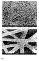
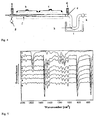
- a 5% solution of poly-L-lactide in dichloromethane (conductivity ⁇ 10 -7 ⁇ S / cm) was prepared in the in Fig. 1 spun electron spinning apparatus at a voltage of 35 kV. The distance of the cannula tip (diameter 0.3 mm) from the substrate plate (glass) was 10 cm. The fibers were used without further treatment. A scanning electron micrograph of the fibers is in Fig. 2 shown.
- Polylactide template fibers prepared by electrospinning according to Example 1 were placed in the sample space of the vapor deposition apparatus shown in FIG. Subsequently, 230 mg of analytically pure [2.2] paracyclophane were evaporated at 220 ° C / 0.1 mbar and at 800 ° C pyrolyzed thereby forming in the sample chamber at about 20 ° C poly (p-xylylene) (PPX).
- the poly (p-xylylene) / polylactide composite fabric was thermally treated in a vacuum oven at 275 ° C / 0.01 bar for 8 hours.
- the degradation of the polylactide template fibers was confirmed by infrared spectroscopy ( Fig. 5 ).
- the formation of poly (p-xylylene) hollow fibers with an inner diameter of approximately 2 ⁇ m-0.1 ⁇ m could be confirmed by scanning electron microscopy ( Fig. 7 . 8th ).
- a fleece of such fibers consists of about 14 vol .-% of poly (p-xylylene) and 86 vol .-% air.
- Polylactide template fibers prepared by electrospinning according to Example 1 were coated with a 4% polyamidocarboxylic acid in water / DMF / pyridine by immersion.
- the polyamidocarboxylic acid / polylactide composite fabric was thermally treated in a vacuum oven at 150-285 ° C / 0.01 mbar for 9 hours.
- the polylactide template fibers were thermally degraded and the polyamidocarboxylic acid was converted into polyimide.
- the formation of polyimide hollow fibers with inside diameters of approximately 1 ⁇ m-0.5 ⁇ m could be confirmed by scanning electron microscopy ( Fig. 10 ).
- Polylactide template fibers prepared by electrospinning (with 0.8% benzyltriethylammonium chloride as an additive in dichloromethane) according to Example 2 were coated in a vapor deposition apparatus with gold from the gas phase. Subsequently, these polylactide / gold fibers were placed in the sample space of the in Fig. 4 placed gas-phase deposition apparatus. Subsequently, 200 mg of analytically pure [2.2] paracyclophane were evaporated at 220 ° C./0.1 mbar and pyrolyzed at 700 ° C., whereby poly (p-xylylene) was formed in the sample chamber at about 20 ° C.
- the poly (p-xylylene) / polylactide composite fabric became thermal in a vacuum oven at 285 ° C / 0.01 mbar for 8 hours treated.
- the formation of poly (p-xylylene) / gold hollow fibers with a mean inner diameter of about 0.3 ⁇ m could be confirmed by scanning electron microscopy ( Fig. 11 ).
- the presence of the gold coating on the inner wall of poly (p-xylylene) hollow fibers was detected by elemental scanning electron microscopy.
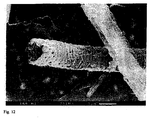
- Polylactide template fibers prepared by electrospinning (with 0.8% benzyltriethylammonium chloride as an additive in dichloromethane) according to Example 2 were coated in a vapor deposition apparatus with aluminum from the gas phase. Subsequently, these polylactide / aluminum fibers were thermally treated in a vacuum oven at 285 ° C / 0.01 mbar for 8 hours. The formation of aluminum hollow fibers with a mean inner diameter of about 0.5 ⁇ m could be confirmed by scanning electron microscopy ( Fig. 12 ). The presence of aluminum was detected by element-specific scanning electron microscopy.
- Polylactide template fibers prepared by electrospinning according to Example 2 were coated in a vapor deposition apparatus with silicon monoxide from the gas phase and by oxygen in silica (glass, detected by infrared and Wide Angle X-Ray spectroscopy ( WAXS)). Subsequently, these polylactide / glass fibers were thermally treated in a vacuum oven at 285 ° C / 0.01 bar for 14 hours. It was demonstrated by IR spectroscopy that the thermal degradation of the polylactide template fibers is quantitative ( Fig. 13 ). The formation of glass hollow fibers with a mean inner diameter of about 0.5 ⁇ m was confirmed by scanning electron microscopy ( Fig. 14 ).
Landscapes
- Chemical & Material Sciences (AREA)
- Chemical Kinetics & Catalysis (AREA)
- Engineering & Computer Science (AREA)
- Life Sciences & Earth Sciences (AREA)
- Electrochemistry (AREA)
- General Chemical & Material Sciences (AREA)
- Inorganic Chemistry (AREA)
- Manufacturing & Machinery (AREA)
- Health & Medical Sciences (AREA)
- Sustainable Energy (AREA)
- Sustainable Development (AREA)
- Mechanical Engineering (AREA)
- Textile Engineering (AREA)
- Molecular Biology (AREA)
- Physics & Mathematics (AREA)
- Organic Chemistry (AREA)
- Immunology (AREA)
- General Physics & Mathematics (AREA)
- General Health & Medical Sciences (AREA)
- Biochemistry (AREA)
- Analytical Chemistry (AREA)
- Dispersion Chemistry (AREA)
- Materials Engineering (AREA)
- Pathology (AREA)
- Chemical Or Physical Treatment Of Fibers (AREA)
- Separation Using Semi-Permeable Membranes (AREA)
- Artificial Filaments (AREA)
- Inorganic Fibers (AREA)
- Carbon And Carbon Compounds (AREA)
- Spinning Methods And Devices For Manufacturing Artificial Fibers (AREA)
- Catalysts (AREA)
Description
- Die Erfindung betrifft Meso- und Nanoröhren, d. h. Röhren oder Hohlfasern mit einem Innendurchmesser im Nano- bis Mikrometer-Bereich gemäß dem Oberbegriff von Anspruch 1, sowie ein Verfahren zur Herstellung einer ersten Ausführungsform dieser Hohlfasern gemäß dem Oberbegriff von Anspruch 11 und ein weiteres Verfahren zur Herstellung einer zweiten Ausführungsform dieser Hohlfasern gemäß dem Oberbegriff von Anspruch 12.
- Als Hohlfasern, Meso- oder Nanoröhren werden allgemein Röhren mit einem Innendurchmesser von unter 0.1 mm bezeichnet
- Röhren oder Hohlfasern mit kleinem Innendurchmesser sind bekannt und werden Insbesondere für Trennzwecke z. B. in der medizinischen Dialyse, für die Gasseperation oder Osmose von wäßrigen Systemen, z. B. zur Wasseraufbereitung eingesetzt (s. Kirk Othmer, Encyclopedia of Chemical Technology, 4 Ed. Vol 13, S. 312-313). Das Fasermaterial besteht meist aus Polymeren, die darüber hinaus Poren, d. h. Eigenschaften von semipermeablen Membranen besitzen können. Die zu Trennzwecken verwendeten Hohlfasern weisen meist eine Oberfläche von 100 cm2 pro cm3 Volumen mit einem Innendurchmesser von 75 µm bis 1 mm auf.
- Eine weitere Anwendung von Hohlfasern ist die Mikroelektronik. Hier werden supraleitende, ca. 60 µm im Durchmesser betragende Fasern aus supraleitendem Material hergestellt, Indem Hohlfasern aus Polymeren mit einer Masse gefüllt werden, die nach thermischem Abbau des Polymeren supraleitende Eigenschaften besitzt (J.C. W. Cien, H. Rinsdorf et al., Adv. Mater., 2 (1990) S. 305).
- Röhren mit kleinem Innendurchmesser werden in der Regel durch Extrusionsspinnverfahren hergestellt eine Reihe von Extrusionsspinnverfahren sind in Kirk-Othmer, Encyclopedia of Chemical Technology, 4. Ed. Vol. 13, S. 317-322 beschrieben.
- überdies beschreibt die
FR-A-1 511 5B1 - Die Zusammenfassung der
JP-A-62110 916 - Mit Hilfe von Extrusionsspinnverfahren können Hohlfasern mit einem Innendurchmesser von bis zu 2 µm hergestellt werden. Die Herstellung von Hohlfasern mit kleineren Innendurchmessern ist mit diesen Verfahren nicht möglich.
- Die deutsche Patentanmeldung
DE-A1-2 823 521 befaßt sich mit der Schaffung einer Wasserstoffpermeationszelle und den hierzu erforderlichen Hohlröhren. Diese besitzen eine Metall-Außenwand aus Nickel und haben einen Innendurchmesser von 1 µm bis 50 µm. - Zur Herstellung von sehr dünnen Fasern ohne Hohlraum kann die Elektrospinning Technik (Electrostatic Spinning) eingesetzt werden. Hier werden Polymerschmeizen oder Polymerlösungen in einem elektrischen Feld durch Kanülen unter einem geringen Druck extrudiert. Grundlagen dieser Technik können z. B. in
EP-A1-0 005 035 ,EP-A2-0 095 940 ,US-PS-5 024 789 oderWO-A1-91/01695 - Hohlfasern mit einem sehr kleinen Innendurchmesser sind bisher nur durch elektrochemische Synthese, so beschrieben in L. A. Chemozantonskli, Chem. Phys. Lett. 297, 257, (1998), durch die Methoden der Supramolekularen Chemie (S. Demoustier - Champagne et al., Europ. Polym. J. 34, 1767, (1998) oder mit selbst-organisierenden Membranen als Template (E. Evans et al. Science, Vol 273, 1996, S. 933-995) zugänglich. Carbonhohlfasern auf Basis der Fullerenchemie (Kohlenstoff-Nanoröhrchen mit ein- und mehrwandigen Strukturen aus einer einzelnen aufgerollten Graphitschicht (Schicht aus allseitig aneinander kondensierten Kohlenstoff-Sechsringen) oder konzentrisch angeordneten Graphitzylindern sind z. B. in "Fullerenes and related Structures", Ed. A. Hirsch, Springer Verlag 1999, S. 189-234 oder N. Grobert, Nachr. Chem. Tech. Lab., 47, (1999), 768-776 beschrieben.
- Diese Methoden sind jedoch nur auf spezielle Materialien anwendbar und können zur Herstellung von technisch verwertbaren, d. h. mechanisch und chemisch stabilen Hohl-fasern nicht eingesetzt werden.
- Für viele Anwendungen z. B. bei der Trennung von Gasen wäre es erwünscht. Hohlfasern mit kleinen Außen- und/oder Innendurchmessern einzusetzen, Insbesondere sollen diese Fasern widerstandsfähig sein.
- Aufgabe der vorliegenden Erfindung war es daher, Hohlfasern aus verschiedenen auf das jeweilige Einsatzgebiet abgestimmten Materialien mit einem Innendurchmesser im nm- bis µm-Bereich bereitzustellen. Diese sollen thermisch, chemisch und mechanisch belastbar und somit technisch anwendbar sein.
- Hauptmerkmale der Erfindung sind in den kennzeichnenden Teilen der Ansprüche 1, 11 und 12 angegeben. Ausgestaltungen sind Gegenstand der Ansprüche 2 bis 10 und 13 bis 28.
- Bei Hohlfasern mit einem Innendurchmesser von 10 nm bis 50 µm und einer Außenwand, aufgebaut aus metallhaltigen anorganischen Verbindungen, Polymeren und/oder Metallen sieht die Erfindung vor, daß die Hohlfasern eine rauhe oder mikrostrukturierte Innenseite aufweisen und ein Verhältnis von Oberfläche zu Volumen zwischen 500 cm2/cm3 und 2.000.000 cm2/cm3 besitzen.
- Diese Hohlfasern haben Innendurchmesser in den gewünschten Dimensionen. Überraschenderweise sind sie thermisch und chemisch stabil sowie präzise aus den verschiedensten Materialien wie Polymeren, Anorganika oder sogar Metallen herzustellen.
- Zur Herstellung von Hohlfasern aus metallhaltigen anorganischen Verbindungen, Polymeren und/oder Metallen sieht der unabhängige Anspruch 11 ein Verfahren vor, für das selbständiger Schutz beansprucht wird. Bei ihm erhält eine Faser aus einem ersten abbaubaren Material mindestens eine Beschichtung aus mindestens einem weiteren Material. Anschließend wird das erste Material mit der Maßgabe abgebaut, daß die so erhaltene Hohlfaser einen Innendurchmesser von 10 nm bis 50 µm aufweist. Erfindungsgemäß zeichnet sich dieses Verfahren dadurch aus, daß die Faser aus dem ersten Material nach der Elektrospinning-Technik hergestellt wird und zwar durch Verarbeitung einer Polymerlösung mit einem leicht verdampfbaren Lösungsmittel. Außerdem besitzt die gebildete Hohlfaser ein Verhältnis von Oberfläche zu Volumen zwischen 500 cm2/cm3 und 2.000.000 cm2/cm3 und weist eine raue oder mikrostrukturierte Innenseite auf.
- Man erkennt, daß durch dieses Verfahren Hohlfasern mit einem Durchmesser bis hinab zu sehr kleinen Nanometerabständen geschaffen werden können. Dabei ist in der Regel der spätere Hohlraum der Hohlfasern ungefähr gleich groß wie der Durchmesser der abbaubaren Fasern, bzw. Beschichtungen. Die verfahrensgemäßen Fasern zeigen eine erstaunlich gute thermische Stabilität, die weit über 100 °C liegt Zudem erlaubt es die Elektrospinning-Technik, Multikomponentenfasern, d. h. Fasern mit unterschiedlichen Materialien in unterschiedlichen Schichten oder Fasern mit bestimmter Oberflächentopographie herzustellen.
- Darüber hinaus läßt sich eine andere Ausführungsform der erfindungsgemäßen aus metallhaltigen anorganischen Verbindungen, Polymeren und/oder Metallen aufgebauten Hohlfasern durch ein weiteres Verfahren gemäß Anspruch 12 herstellen. Dieses beansprucht ebenfalls selbständige Schutz und bestimmt, daß eine Faser eines ersten Materials nacheinander mit einem zweiten abbaubaren Material und mindestens einem weiteren Material beschichtet wird. Danach wird das zweite Material abgebaut, wobei bezogen auf das mindestens eine weitere Material eine Hohlfaser mit einem innendurchmesser von 10 nm bis 50 µm und einem Kern aus dem ersten Material erhalten wird. Erfindungsgemäß stellt man die nicht abbaubare Faser aus dem ersten Material nach der Elektrospinning-Technik durch Verarbeitung einer Polymerlösung mit einem leicht verdampfbaren Lösungsmittel her. Die gebildete Hohlfaser besitzt ein Verhältnis von Oberfläche zu Volumen zwischen 500 cm2/cm3 und 2.000.000 cm2/cm3 und weist eine raue oder mikrostrukturierte Innenseite auf.
- Ein derartiges Verfahren macht ebenfalls Hohlfasern mit sehr kleinem Durchmesser zugänglich. Jedoch zeichnen sich diese durch eine zusätzlich darin vorhandene Kernfaser bzw. einen Kern aus, der bevorzugt einen mittleren Abstand von 10 bis 300 nm zur Außenwand aufweist.
- Die erfindungsgemäßen Hohlfasern weisen bevorzugt Innendurchmesser von 50 nm bis 20 µm, besonders bevorzugt 100 nm bis 5 µm, ganz besonders bevorzugt 100 nm bis 2 µm, bzw. 100 nm bis 1 µm, 500 nm bis 1 µm, 10 nm bis 1 µm oder 100 nm bis 500 nm auf.
- Die Länge der Hohlfasern ist vom Verwendungszweck bestimmt und beträgt in der Regel 50 µm bis zu mehreren mm oder cm.
- Die Wandstärke, d. h. die Dicke der Außenwände der Hohlfasern ist variabel und beträgt in der Regel 10 bis 5000 nm, bevorzugt 10 bis 1000 nm, besonders bevorzugt 10 bis 250 nm.
- Hohlfasern gemäß der vorliegenden Erfindung weisen neben den sehr kleinen Innendurchmessern eine Reihe von Eigenschaften auf, die sie für eine Verwendung in den Bereichen Medizin, Elektronik, Katalyse, chemische Analytik, Gasseparation, Osmose oder der Optik geeignet machen.
- Sie können gegebenenfalls eine poröse Oberfläche aufweisen und/oder wahlweise elektrische Leiter oder Isolatoren sein
- Ferner können die Außenwände der erfindungsgemäßen Hohlfasern aus den unterschiedlichsten Materialien aufgebaut sein, wie zu Beispiel aus Polymeren, Metallen oder metallhaltigen anorganischen Verbindungen. Die Außenwände können eine Schicht dieser Materialien aufweisen, d. h. vollständig aus diesen bestehen oder mehrere Schichten aus den gleichen oder unterschiedlichen Materialien besitzen. Der sehr kleine Innendurchmesser sorgt für ein sehr hohes Verhältnis von Oberfläche zum Volumen der Hohlfasern; dieses kann zwischen 500 und 2.000.000 cm2/cm3, bevorzugt 5.000 bis 1.000.000 cm2/cm3, besonders bevorzugt 5.000 bis 500.000 cm2/cm3 betragen.
- Die metallhaltigen, anorganischen Verbindungen der erfindungsgemäßen Hohlfasern sind z.B. Fluorierte Ethylene oder Therephthalate.
- Die Beschichtung, d. h. der Aufbau der Außenwand der Hohlfasern kann aus Metallen der Gruppen Ia, Ib, IIa, IIb, IIIa, IIIb, IVa, IVb, Vb, VIb, VIIb und/oder VIIIb des Periodensystems jeweils als Reinmetall oder Legierung bestehen. Geeignete Metalle sind beispielsweise Gold, Palladium, Aluminium, Platin, Silber, Titan, Kobalt, Ruthenium, Rhodium, Natrium, Kalium, Calzium, Lithium, Vanadium, Nickel, Wolfram, Chrom, Mangan und/oder Silicium. Die Beschichtung kann durch Bedampfen mit den Metallen oder durch Zersetzung geeigneter metallorganischer Verbindungen mit CVD-Verfahren erfolgen.
- Polymere Beschichtungsmaterialien können weiterhin funktionelle Gruppen wie Ester, Amide, Amine, Silylgruppen, Siloxangruppen, Thiole, Hydroxylgruppen, Urethangruppen, Carbamatgruppen, Nitrilgruppen, C=C-Gruppen, C=C-Gruppen, Carbonsäurehalogenidgruppen, Sulfoxidgruppen, Sulfongruppen, Pyridylgruppen, Arylphosphingruppen oder auch ionische Gruppen wie Carbonsäuren, Sulfonsäuren oder quartäre Amine tragen Die funktionellen Gruppen können an der Innen- und/oder Außenseite der Hohlfasern angebracht sein und die Oberflächeneigenschaften der Hohlfasern bei Trenn- oder Osmoseverfahren verbessern. Die funktionellen Gruppen können auch nachträglich durch polymeranaloge Umsetzungen chemisch verändert werden (z. B. Verseifen von Estern).
- Durch eine entsprechende Funktionalisierung können auch Wirkstoffe wie Antibiotika, Anästhetika, Proteine wie Insulin, Antifouling Agentien, Agrochemikalien wie Herbizide oder Fungizide reversibel in den Hohlfasern fixiert und/oder langsam mit konstanter Konzentration wieder abgegeben (Controlled bzw. Slow-Release) werden.
- Die Außenwand der Hohlfasern, d. h. das nicht-abbaubare weitere Material kann auch aus Glas, Glaskeramiken, SiOx, Perowskit, Keramiken, Aluminiumoxiden oder Zirkoniumoxiden, optional aus Siliziumkarbid, Bornitrid, Kohlenstoff sowie Metalloxiden aufgebaut sein. Hier bieten sich ebenfalls Gasphasenabscheideverfahren (CVD oder PVD) oder auch Hydrothermalverfahren an.
- Geeignet sind Perowskite der allgemeinen Formel
LaXYMgO
- Der Abbau des abbaubaren Materials kann thermisch, chemisch, strahleninduziert, biologisch, photochemisch, durch Plasma, Ultraschall, Hydrolyse oder durch Extraktion mit einem Lösungsmittel erfolgen. In der Praxis hat sich der thermische Abbau bewährt. Die Zersetzungsbedingungen liegen je nach Material bei 100-500 °C und 0.001 mbar bis 1 bar, besonders bevorzugt bei 0.001 bis 0.1 mbar. Durch den Abbau des Materials wird eine Hohlfaser erhalten, deren Wandmaterial aus den Beschichtungsmaterialien besteht.
- Wie in
Fig. 1 b, c und d gezeigt, können auch mehrere Schichten aus verschiedenen Materialien auf die Faser aufgebracht werden. Es werden so Hohlfasern erhalten, die unterschiedliche Innen- und Außenwände aufweisen bzw die Außenwände der Hohlfasern können aus mehreren Schichten aufgebaut werden. Die unterschiedlichen Schichten können unterschiedliche Funktionen erfüllen; so kann die innere Schicht besondere Trenneigenschaften für z. B. chromatographische Zwecke und die äußere Schicht eine hohe mechanische Stabilität aufweisen. - Beispielhaft seien die folgenden Schichtabfolgen der erfindungsgemäßen Hohlfasern genannt:
- Glas / Metall
- Metall / Glas
- Glas / Polymer
- Polymer / Glas
- Polymer / Polymer
- Metall / Metall
- Metallhaltige anorganische Verbindung / Metallhaltige anorganische Verbindung
- Keramik / Keramik
- Polymer / Metall
- Metall / Polymer
- Keramik / Polymer
- Polymer / Keramik
- Metall / Keramik
- Keramik / Metall
- Polymer / Metall / Polymer
- Metall / Polymer / Metall
- Metall / Keramik / Metall
- Polymer / Keramik / Polymer
- Keramik / Polymer / Keramik
- Polymer / Glas/Polymer
- Glas / Polymer / Glas
- Erfindungsgemäße Hohlfasern mit oder ohne Kern können insbesondere als Separations- oder Speichermedium für Gase, Flüssigkeiten oder Partikelsuspensionen und zur Filtration oder Reinigung von Stoffgemischen verwendet werden. Hier bietet sich der Einsatz als Membrane für Gase, insbesondere H2 oder Flüssigkeiten, zur Partikelfiltration, in der Chromatographie, zur Öl-/Wassertrennung, als Ionenaustauscher in der Dialyse, zur Größenseparation von Zellen, Bakterien oder Viren, als Bestandteil einer künstlichen Lunge, zur Entsalzung zur Ent- oder Bewässerung oder als Filter zur Entwässerung von Treibstoffen an.
- Weiterhin können erfindungsgemäße Hohlfasern in der Sensorik für Lösungsmittel-, Gas-, Feuchte- oder Biosensoren, in der Kapillarelektrophorese, in katalytischen Systemen, in der Rastersondenmikroskopie oder als Werkstoffe in der Superleichtbauweise, als mechanische Verstärkung analog zu Glasfasern, als Schall- oder Schwingungsschutz als Verbundwerkstoff oder Füllstoff, als Controlled-Release- oder Drug-Delivery-System, in medizinischen Separationstechniken, in der Dialyse, als künstliche Lunge, Proteinspeicher oder im Tissue Engineering verwendet werden.
- In der Bekleidunas-/Textilindustrie können die erfindungsgemäßen Hohlfasern als Wärmeisolator in Kleidung oder Schlafsäcken, in photo- oder thermochromer Bekleidung durch Einbetten von Farbstoffen im Röhreninnern oder als Kennzeichner durch Marker im Röhreninneren verwendet werden.
- Außerdem finden erfindungsgemäße Hohlfasern in der Elektronik, Optik oder der Energiegewinnung Verwendung So können aus den Hohlfasern Drähte, Kabel oder Kapazitäten, Mikromaschinen (z. B. für piezoelektrische Verformung, Nanoperistaltikpumpen oder zur Verformung von photoadressierbaren Polymeren) oder Interlayer Dielektrika, hergestellt werden. Weitere Verwendungen für erfindungsgemäße Hohlfasern sind Mikroreaktoren z. B. für katalytische Reaktionen, Templatereaktionen und Bioreaktoren, die Wärmeerzeugung durch Umwandlung von Sonnenlicht (Solar-α-Systeme), in der Chiptechnologie als flexible Devices oder Mikroskopie als Sensorbestandteil (z. B. als Spitzen oder Sonden für Rastersondenmikroskope oder SNOM-Geräte).
- Die erfindungsgemäßen Hohlfasern weisen eine sehr niedrige Dielektrizitätskonstante auf und können daher auch als Dielektrikum, insbesondere als Interlayer-Dielektrikum in elektronischen Bauteilen, z. B. bei der Chipherstellung verwendet werden. Bei der Produktion neuer Chip-Generationen mit noch kleineren Dimensionen bzw höheren Speicherdichten sind Interlayer-Dielektrika mit einer niedrigen Dielektrizitätskonstante wichtig. Die erfindungsgemäßen Hohlfasern weisen aufgrund des hohen Anteils an umschlossener Luft pro Volumen einen DK-Wert von kleiner als 4, bevorzugt kleiner 3, ganz besonders bevorzugt kleiner 2 und im Idealfall kleiner 1.5 auf
- Die Hohlfasern werden für die Verwendung als Dielektrikum bevorzugt als Flies oder Matte (z. B. nach
Fig. 2 oder3 ) eingesetzt. - Durch die große Oberfläche der erfindungsgemäßen Hohlfasern können diese auch in Brennstoffzellen, Batterien oder in elektrochemischen Reaktionen verwendet werden Vorteilhaft besteht die Außenwand der Hohlfasern für solche Verwendungen aus Sauerstoffionenleiltern wie z. B. Perowskiten. Bei Oxidationsreaktionen können die Hohlfasern vom Edukt (z. B. einem Olefin) umspült werden, während durch die Hohlräume der Fasern Sauerstoff geleitet wird. Das Oxidationsprodukt wird außen an den Hohlfasern gebildet und abgeführt
- Die erfindungsgemäßen Hohlfasern können als katalytisches System verwendet werden. So können beispielsweise Hohlfasern aus Edelmetallen wie Platin oder Palladium als Entstickungskatalysatoren in Kraftfahrzeugen eingesetzt werden.
- Erfindungsgemäße Hohlfasern aus zellverträglichen Materialien oder mit entsprechend modifizierten Oberflächen können in Zellmembranen eingebunden oder eingeführt werden und für die Separation sowie Gewinnung oder Entnahme von Stoffwechselmetaboliten, Enzymen und anderen Komponenten des Zytoplasmas innerhalb von Zellen oder zytoplasmatischen Komponenten verwendet und damit für die Gewinnung von Biopharmaka eingesetzt werden. Die folgenden Beispiele sollen die Erfindung näher erläutern, ohne ihren Umfang zu beschränken.
- Eine 5% ige Lösung von Poly-L-lactid in Dichlormethan (Leitfähigkeit < 10-7 µS/cm) wurde in der in
Abb. 1 gezeigten Electrospinnapparatur bei einer Spannung von 35 kV versponnen. Der Abstand der Kanülenspitze (Durchmesser 0.3 mm) von der Substratplatte (Glas) betrug 10 cm. Die Fasern wurde ohne weitere Behandlung weiterverwendet. Eine rasterelektronenmikroskopische Aufnahme der Fasern ist inFig. 2 gezeigt. - Eine 5% ige Lösung von Poly-L-lactid mit 1.5% Benzyltriethylammoniumchlorid in Dichlormethan (Leitfähigkeit = 417 µS/cm) wurde in der in
Abb. 1 gezeigten Electrospinnapparatur bei einer Spannung von 35 kV versponnen. Der Abstand der Kanülenspitze (Durchmesser 0.3 mm) von der Substratplatte (Glas) betrug 10 cm. Die Fasern wurde ohne weitere Behandlung weiterverwendet. Eine rasterelektronenmikroskopische Aufnahme der Fasern ist inFig. 3 gezeigt. - Polylactid-Templatfasern, hergestellt durch Electrospinning gemäß Beispiel 1 wurden in dem Probenraum der in Abb 4 gezeigten Gasphasenabscheidungsapparatur plaziert. Anschließend wurden 230 mg analysenreines [2.2]Paracyclophan bei 220°C/0.1 mbar verdampft und bei 800°C pyrolysiert wodurch sich im Probenraum bei ca 20°C Poly(p-xylylen) (PPX) bildete. Das Poly(p-xylylen)/Polylactid Compositgewebe wurde in einem Vakuumofen bei 275°C/0.01 bar 8 Stunden thermisch behandelt. Der Abbau der Polylactid-Templatfasern konnte durch Infrarotspektroskopie belegt werden (
Abb. 5 ). Die Bildung von Poly(p-xylylen)-Hohlfasern mit einem Innendurchmessern von ca 2 µm - 0.1 µm konnte durch Rasterelektronen-mikroskopie belegt werden (Fig. 7 ,8 ). - Auf diese Weise hergestellte Poly-(p-xylylen)-Hohlfasern besitzen eine Dichte von 0.15 g/cm3 bei einem DK-Wert von 1.29 (Luft = 1). Ein Flies aus solchen Fasern besteht zu ca. 14 Vol.-% aus Poly-(p-xylylen) und 86 Vol.-% Luft.
- Polylactid-Templatfasern hergestellt durch Electrospinning gemäß Beispiel 1 wurden mit einer 4%igen Polyamidocarbonsäure in Wasser/DMF/Pyridin durch Eintauchen beschichtet. Das Polyamidocarbonsäure/Polylactid Compositgewebe wurde in einem Vakuumofen bei 150-285 °C/0.01 mbar 9 Stunden thermisch behandelt. Dabei wurde einerseits die Polylactid-Templatfasern thermisch abgebaut und die Polyamidocarbonsäure in Polyimid überführt Die Bildung von Polyimid-Hohlfasern mit Innendurchmessern von ca 1 µm - 0.5 µm konnte durch Rasterelektronenmikroskopie belegt werden (
Fig. 10 ). - Polylactid-Templatfasern hergestellt durch Electrospinning (mit 0.8 % Benzyltriethylammoniumchlorid als Zusatz in Dichlormethan) gemäß Beispiel 2 wurden in einer Bedampfungsapparatur mit Gold aus der Gasphase beschichtet. Anschließend wurden diese Polylactid/Gold-Fasern in dem Probenraum der in
Fig. 4 gezeigten Gasphasenabscheidungs-apparatur plaziert. Anschließend wurden 200 mg analysenreines [2.2]Paracyclophan bei 220 °C/0.1 mbar verdampft und bei 700 °C pyrolysiert, wodurch sich im Probenraum bei ca 20°C Poly(p-xylylen) bildete. Das Poly(p-xylylen)/Polylactid Compositgewebe wurde in einem Vakuumofen bei 285°C/0.01 mbar 8 Stunden thermisch behandelt. Die Bildung von Poly(p-xylylen)/Gold-Hohlfasern mit einem mittleren Innendurchmesser von ca 0.3 µm konnte durch Rasterelektronenmikroskopie belegt werden (Fig. 11 ). Das Vorhandensein der Goldbeschichtung an der Innenwand der Poly(p-xylylen)-Hohlfasern wurde durch elementspezifische Rasterelektronenmikroskopie nachgewiesen werden. - Polylactid-Templatfasern hergestellt durch Electrospinning (mit 0,8 % Benzyltriethylammoniumchlorid als Zusatz in Dichlormethan) gemäß Beispiel 2 wurden in einer Bedampfungsapparatur mit Aluminium aus der Gasphase beschichtet. Anschließend wurden diese Polylactid/Aluminium-Fasern in einem Vakuumofen bei 285 °C/0.01 mbar 8 Stunden thermisch behandelt. Die Bildung von Aluminium-Hohlfasern mit einem mittleren Innendurchmesser von ca 0.5 µm konnte durch Rasterelektronenmikroskopie belegt werden (
Fig. 12 ). Das Vorhandensein von Aluminium wurde durch elementspezifische Rasterelektronenmikroskopie nachgewiesen. - Polylactid-Templatfasern, hergestellt durch Electrospinning gemäß Beispiel 2 (mit 0.8 % Benzyltriethylammoniumchlorid als Zusatz in Dichlormethan) wurden in einer Bedampfungsapparatur mit Siliciummonoxid aus der Gasphase beschichtet und durch Sauerstoff in Siliciumdioxid (Glas, nachgewiesen durch Infrarot- und Wide Angle X-Ray Spektroskopie (WAXS)) überführt, Anschließend wurden diese Polylactid/Glas-Fasern in einem Vakuumofen bei 285 °C/0.01 bar 14 Stunden thermisch behandelt. Mittels IR-Spektroskopie konnte nachgewiesen werden, daß der thermische Abbau der Polylactid-Templatfasern quantitativ ist (
Abb. 13 ). Die Bildung von Glas-Hohlfasern mit einem mittleren Innendurchmesser von ca 0.5 µm wurde durch Rastereleklronenmikroskopie belegt (Fig. 14 ). -
-
Fig. 1 . Schematische Darstellung einer Electrospinnapparatur -
Fig. 2 . Polylactid-Templatfasern hergestellt durch Electrospinning aus Dichlormethan ohne Zusatz (Beispiel 1) -
Fig. 3 . Polylactid-Templatfasern hergestellt durch Electrospinning aus Dichlormethan mit Zusatz (Beispiel 2) -
Fig. 4 . Schematische Darstellung einer Gasphasenabscheidungsapparatur für Poly(p-xylylen), mit a) Druckmessung, b) Verdampfungszone, c) Pyrolysezone, d) Druckmessung, e) Probenraum, f) Quarzschiffchen für Startmaterial, g) Rezipient zur Druckregulierung, h) Pyrolyseöle, i) Kühlfalle, k) Vakuum -
Fig. 5 . Infrarotspektroskopische Untersuchung des thermischen Abbaus von Poly(p-xylylen)-beschichteten Polylactid-Templatfasern bei 265°C/0.01 bar und verschiedenen Zeiten b = 0 Std., c = 1 Std, d = 2 Std, e = 3 Std, f = 4 Std, g = 6 Std und der reinen Polymere Polylactid = a und Poly(p-xylylen) = h. -
Fig. 6 . Photographie eines Poly(p-xylylen)-Hohlfasergewebes -
Fig. 7 Rasterelektronenmikroskopische Aufnahmen von Poly(p-xylylen)-Hohlfasern nach Entfernung der Polylactid-Templatfasern (Beispiel 3). -
Fig.8 . Rasterelektronenmikroskopische Aufnahmen von Poly(p-xylylen)-Hohlfasern nach Entfernung der Polylactid-Templatfasern (Die Polylactid-Templatfasern hergestellt durch Electrospinning aus Dichlormethan mit 0.8 % Benzyltriethylammoniumchlorid) -
Fig.9 . Rasterelektronenmikroskopische Aufnahme von Poly(p-xylylen)-Hohlfasern nach Entfernung der Polylactid-Templatfasern mit Blick auf die Topologie der Hohlfaserinnenwände. -
Fig. 10 . Rasterelektronenmikroskopische . Aufnahme von Polyimid-Hohlfasern nach Entfernung der Polylactid-Templatfasern (Beispiel 4) -
Fig. 11 . Rasterelektronenmikroskopische Aufnahme von PPX-Hohlfasern nach Entfernung der Polylactid-Templatfasern mit innerer Goldbeschichtung (Beispiel 5). -
Fig. 12 . Rasterelektronenmikroskopische Aufnahme von Aluminium-Hohlfasern nach Entfernung der Polytactid-Templatfasern (Beispiel 6) -
Fig. 13 . Infrarotspektrum der Glashohlfasern nach Degradation der der Polylactid-Templatfasern -
Fig. 14 . Rasterelektronenmikroskopische Abbildung von Glas-Hohlfasern
Claims (28)
- Hohlfasern mit einem Innendurchmesser von 10 nm bis 50 µm und einer Außenwand, aufgebaut aus metallhaltigen anorganischen Verbindungen, Polymeren und/oder Metallen, dadurch gekennzeichnet, daß die Hohlfasern eine rauhe oder mikrostrukturierte Innenseite aufweisen und ein Verhältnis von Oberfläche zu Volumen zwischen 500 cm2/cm3 und 2.000.000 cm2/cm3 besitzen.
- Hohlfasern nach Anspruch 1, dadurch gekennzeichnet, daß deren Innendurchmesser 10 nm bis 1 µm beträgt.
- Hohlfasern nach einem der Ansprüche 1 oder 2, dadurch gekennzeichnet, daß die Außenwand der Hohlfasern aus Poly(p-xylylen), Polyacrylamid, Polyimiden, Polyestern, Polyolefinen, Polycarbonaten, Polyamiden, Polyethern, Polyphenylen, Polysilanen, Polysiloxanen, Polybenzimidazolen, Polybenzthiazolen, Polyoxazolen, Polysulfiden, Polyesteramiden, Polyarylenvinylenen, Polylactiden, Polyetherketonen, Polyurethanen, Polysulfonen, Ormoceren, Polyacrylaten, Siliconen, vollaromatischen Copolyestern, Poly-N-vinylpyrrolidon, Polyhydroxyethylmethacrylat, Polymethylmethacrylat, Polyethylenterephthalat, Polybutylentherephthalat, Polymethacrylnitril, Polyacrylnitril, Polyvinylacetat, Neopren, Buna N, Polybutadien, Polytetrafluorethen, Cellulose (modifiziert oder nichtmodifiziert), Alginaten oder Collagen, deren Homo- oder Copolymerisaten und/oder Blends aufgebaut ist.
- Hohlfasern nach einem der Ansprüche 1 oder 2, dadurch gekennzeichnet, daß die Außenwand der Hohlfasern aus Metallen der Gruppen Ia, Ib, IIa, IIb, IIIa, IIIb, IVa, IVb, Vb, VIb, VIIb und/oder VIIIb des Periodensystems, jeweils als Reinmetall oder Legierung aufgebaut ist.
- Hohlfasern nach einem der Ansprüche 1 oder 2, dadurch gekennzeichnet, daß die Außenwand der Hohlfasern aus Glas, Glaskeramiken, SiOx, Perowskit, Keramiken, Aluminiumoxiden oder Zirkonoxiden aufgebaut ist.
- Hohlfasern nach einem der Ansprüche 1 bis 5, dadurch gekennzeichnet, daß die Außenwand der Hohlfasern aus mehreren Schichten aufgebaut ist.
- Hohlfasern nach einem der Ansprüche 1 bis 6, dadurch gekennzeichnet, daß die Hohlfasern einen Kern aufweisen.
- Hohlfasern nach Anspruch 7, dadurch gekennzeichnet, daß der Kern einen mittleren Abstand zur Außenwand von 10 bis 300 nm aufweist.
- Hohlfasern nach einem der Ansprüche 7 oder 8, dadurch gekennzeichnet, daß der Kern aus anorganischen Verbindungen, keramischen Fasern. Kohlenstoffasem, Polymeren und/oder Metallen aufgebaut ist.
- Hohlfasern nach einem der Ansprüche 1 bis 9, gekennzeichnet durch eine Dielektrizitätskonstante von kleiner 4.
- Verfahren zur Herstellung von Hohlfasern aus metallhaltigen anorganischen Verbindungen, Polymere und/oder Metallen,- bei dem eine Faser aus einem ersten abbaubaren Material mindestens eine Beschichtung aus mindestens einem weiteren Material erhält,- anschließend das erste Material mit der Maßgabe abgebaut wird, daß die so erhaltene Hohlfaser einen Innendurchmesser von 10 nm bis 50 µm aufweist,dadurch gekennzeichnet, daß die Faser aus dem ersten Material nach der Elektrospinning-Technik hergestellt wird und zwar durch Verarbeitung einer Polymerlösung mit einem leicht verdampfbaren Lösungsmittel, und- daß die Hohlfaser ein Verhältnis von Oberfläche zu Volumen zwischen 500 cm2/cm3 und 2.000.000 cm2/cm3 besitzt und eine raue oder mikrastrukturierte Innenseite aufweist.
- Verfahren, zur Herstellung von Hohlfasern aus metallhaltigen anorganischen Verbindungen. Polymeren und/oder Metallen,- bei dem eine Faser eines ersten Materials nacheinander mit einem zweiten abbaubaren Material und mindestens einem weiteren Material beschichtet- und das zweite Material mit der Maßgabe abgebaut wird, dass bezogen auf das mindestens eine weitere Material eine Hohlfaser mit einem Innendurchmesser von 10 nm bis 50 µm und einem Kern aus dem ersten Material erhalten wird,dadurch gekennzeichnet, daß die Faser aus dem ersten Material nach der Elektrospinning-Technik durch Verarbeitung einer Polymerlösung mit einem leicht verdampfbaren Lösungsmittel hergestellt wird und nicht abbaubar ist und daß- die Hohlfaser ein Verhältnis von Oberfläche zu Volumen zwischen 500 cm2 /cm3 und 2.000.000 cm2/cm3 besitzt sowie eine raue oder mikrostrukturierte Innenseite aufweist.
- Verfahren nach einem der Ansprüche 11 oder 12, dadurch gekennzeichnet, daß das weitere Material aus anorganischen Verbindungen, Polymeren und/oder Metallen aufgebaut ist.
- Verfahren nach einem der Ansprüche 11 bis 13, dadurch gekennzeichnet, daß das weitere Material aus Poly(p-xylylen), Polyacrylamid, Polyimiden, Polyestern, Polyolefinen, Polycarbonaten, Polyamiden, Polyethern, Polyphenylen, Polysilanen, Polysiloxanen, Polybenzimidazolen, Polybenzthiazolen, Polyoxazolen, Polysulfiden, Polyesteramiden, Polyarylenvinylenen, Polylactiden, Polyetherketonen, Polyurethanen, Polysulfonen, Ormoceren, Polyacrylaten, Siliconen, vollaromatischen Copolyestern, Poly-N-vinylpyrrolidon, Polyhydroxyethylmethacrylat, Polymethylmethacrylat. Polyethylenterephthalat, Polybutylentherephthalat, Polymethacrylnitril, Polyacrylnitril, Polyvinylacetat. Neopren, Buna N, Polybutadien, Polytetrafluorethen, Cellulose (modifiziert oder nichtmodifiziert), Alginaten oder Collagen, deren Homo- oder Copolymerisaten und/oder Blends besteht.
- Verfahren nach einem der Ansprüche 11 bis 13, dadurch gekennzeichnet, daß das weitere Material aus Metallen der Gruppen Ia, Ib, IIa, IIb, IIIa, IIIb, IVa, IVb, Vb, VIb, VIIb und/oder VIIIb des Periodensystems, jeweils als Reinmetall oder Legierung, besteht.
- Verfahren nach einem der Ansprüche 11 bis 13, dadurch gekennzeichnet, daß das weitere Material aus Metalloxiden, Glas, Glaskeramiken, SiOx, Perowskit, Keramiken, Aluminiumoxiden, Siliziumcarbid, Bornitrid, Kohlenstoff oder Zirkoniumoxiden besteht.
- Verfahren nach einem der Ansprüche 11 bis 14, dadurch gekennzeichnet, daß das weitere Material durch Polymerisation, Polykondensation oder Polyaddition eines oder mehrerer Monomeren erhalten wird.
- Verfahren nach Anspruch 17, dadurch gekennzeichnet, daß das weitere Material durch Homo- oder Copolymerisation, -addition oder -kondensation von Methacrylat, Styrol, Styrolsulfonat, 1,6-Hexamethylendiisocyanat (HDI), 4.4'-Methylenbiscyclohexyldiisocyanat (HMDI), 4,4'-Methylenbis-(benzyldiisocyanat) (MDI), 1,4-Butandiol, Ethylendiamin, Ethylen, Styrol, Butadien, Buten-1, Buten-2, Vinylalkohol, Acrylnitril, Methylmethacrylat, Vinylchlorid, fluorierten Ethylenen und/oder Therephthalat erhalten wird.
- Verfahren nach einem der Ansprüche 11 bis 18, dadurch gekennzeichnet, daß der Abbau des abbaubaren Materials thermisch, chemisch, biologisch, strahleninduziert, photochemisch, durch Plasma, Ultraschall oder Extraktion mit einem Lösungsmittel verfolgt.
- Verwendung der Hohlfasern gemäß einem der Ansprüche 1 bis 10 als Separationsmedium oder Speichermedium für Gase, Flüssigkeiten oder Partikelsuspensionen.
- Verwendung der Hohlfasern gemäß einem der Ansprüche 1 bis 10 in der Dialyse, als künstliche Lunge, Proteinspeicher, Controlled Release oder Drug Delivery System oder in medizinischen Separationstechniken.
- Verwendung der Hohlfasern gemäß einem der Ansprüche 1 bis 10 in der Zelltechnologie zur Entnahme von Stoffwechselmetaboliten, Enzymen und anderen Komponenten des Zytoplasmas zu ihrer Separierung und/oder Gewinnung von Biopharmaka.
- Verwendung der Hohlfasern gemäß einem der Ansprüche 1 bis 10 als Sensorbestandteil, als Mikroreaktor oder in der Mikroelektronik als Draht, Kabel oder Kapazität.
- Verwendung der Hohlfasern gemäß einem der Ansprüche 1 bis 10 in der Superleichtbautechnik, als Verbundwerkstoff, als Füllstoff, als mechanische Verstärkung, als Wärmeisolator oder in der Bekleidungsindustrie.
- Verwendung der Hohlfasern gemäß einem der Ansprüche 1 bis 10 in Brennstoffzellen, Batterien oder in elektrochemischen Reaktionen.
- Verwendung der Hohlfasern gemäß einem der Ansprüche 1 bis 10 in der Kapillarelektrophorese, in der Rastersondenmikroskopie oder in katalytischen Systemen.
- Verwendung der Hohlfasern gemäß einem der Ansprüche 1 bis 10 als Dielektrikum.
- Verwendung der Hohlfasern gemäß einem der Ansprüche 1 bis 10 als Interlayer Dielektrikum in der Chipherstellung.
Applications Claiming Priority (5)
| Application Number | Priority Date | Filing Date | Title |
|---|---|---|---|
| DE19935388 | 1999-07-29 | ||
| DE19935388 | 1999-07-29 | ||
| DE10023456 | 2000-05-12 | ||
| DE10023456A DE10023456A1 (de) | 1999-07-29 | 2000-05-12 | Meso- und Nanoröhren |
| PCT/EP2000/006671 WO2001009414A1 (de) | 1999-07-29 | 2000-07-13 | Meso- und nanoröhren |
Publications (2)
| Publication Number | Publication Date |
|---|---|
| EP1200653A1 EP1200653A1 (de) | 2002-05-02 |
| EP1200653B1 true EP1200653B1 (de) | 2008-07-30 |
Family
ID=26005664
Family Applications (1)
| Application Number | Title | Priority Date | Filing Date |
|---|---|---|---|
| EP00949327A Expired - Lifetime EP1200653B1 (de) | 1999-07-29 | 2000-07-13 | Meso- und nanoröhren |
Country Status (7)
| Country | Link |
|---|---|
| US (1) | US6667099B1 (de) |
| EP (1) | EP1200653B1 (de) |
| AT (1) | ATE403019T1 (de) |
| DE (2) | DE10023456A1 (de) |
| ES (1) | ES2311467T3 (de) |
| TW (1) | TW522043B (de) |
| WO (1) | WO2001009414A1 (de) |
Cited By (1)
| Publication number | Priority date | Publication date | Assignee | Title |
|---|---|---|---|---|
| DE102009006943A1 (de) | 2009-01-30 | 2010-08-05 | Philipps-Universität Marburg | Verfahren zur Herstellung photovernetzbarer Nanopartikel im kontinuierlichen Reaktor |
Families Citing this family (83)
| Publication number | Priority date | Publication date | Assignee | Title |
|---|---|---|---|---|
| DE10040897B4 (de) * | 2000-08-18 | 2006-04-13 | TransMIT Gesellschaft für Technologietransfer mbH | Nanoskalige poröse Fasern aus polymeren Materialien |
| TW531928B (en) * | 2000-09-29 | 2003-05-11 | Sony Corp | Fuel cell |
| DE10053263A1 (de) | 2000-10-26 | 2002-05-08 | Creavis Tech & Innovation Gmbh | Orientierte Meso- und Nanoröhrenvliese |
| DE10116232A1 (de) | 2001-04-02 | 2002-10-10 | Creavis Tech & Innovation Gmbh | Verfahren zur Herstellung von Formkörpern mit innenbeschichteten Hohlräumen |
| DE10133393B4 (de) * | 2001-07-13 | 2007-08-30 | TransMIT Gesellschaft für Technologietransfer mbH | Röhrchen mit Innendurchmessern im Nanometerbereich |
| US6764628B2 (en) * | 2002-03-04 | 2004-07-20 | Honeywell International Inc. | Composite material comprising oriented carbon nanotubes in a carbon matrix and process for preparing same |
| DE10210626A1 (de) * | 2002-03-11 | 2003-09-25 | Transmit Technologietransfer | Verfahren zur Herstellung von Hohlfasern |
| AU2003265247A1 (en) * | 2002-06-18 | 2003-12-31 | The University Of Akron | Fibrous protein-immobilization systems |
| WO2004067259A1 (en) | 2002-12-23 | 2004-08-12 | Microcell Corporation | Substrate-supported process for manufacturing microfibrous fuel cells |
| US7229712B2 (en) * | 2003-03-07 | 2007-06-12 | Microcell Corporation | Fuel cell structures and assemblies |
| US7972616B2 (en) * | 2003-04-17 | 2011-07-05 | Nanosys, Inc. | Medical device applications of nanostructured surfaces |
| US20050038498A1 (en) * | 2003-04-17 | 2005-02-17 | Nanosys, Inc. | Medical device applications of nanostructured surfaces |
| US20060122596A1 (en) * | 2003-04-17 | 2006-06-08 | Nanosys, Inc. | Structures, systems and methods for joining articles and materials and uses therefor |
| US7074294B2 (en) * | 2003-04-17 | 2006-07-11 | Nanosys, Inc. | Structures, systems and methods for joining articles and materials and uses therefor |
| US7803574B2 (en) * | 2003-05-05 | 2010-09-28 | Nanosys, Inc. | Medical device applications of nanostructured surfaces |
| US7682654B2 (en) * | 2003-06-03 | 2010-03-23 | Seldon Technologies, Llc | Fused nanostructure material |
| US20050112450A1 (en) * | 2003-09-08 | 2005-05-26 | Intematix Corporation | Low platinum fuel cell catalysts and method for preparing the same |
| US8211593B2 (en) | 2003-09-08 | 2012-07-03 | Intematix Corporation | Low platinum fuel cells, catalysts, and method for preparing the same |
| US7351444B2 (en) * | 2003-09-08 | 2008-04-01 | Intematix Corporation | Low platinum fuel cell catalysts and method for preparing the same |
| US20050118494A1 (en) * | 2003-12-01 | 2005-06-02 | Choi Sung H. | Implantable biofuel cell system based on nanostructures |
| CN100410429C (zh) * | 2003-12-10 | 2008-08-13 | 同济大学 | 制备共轴复合连续纳/微米纤维的多喷头静电纺丝装置 |
| US20110039690A1 (en) | 2004-02-02 | 2011-02-17 | Nanosys, Inc. | Porous substrates, articles, systems and compositions comprising nanofibers and methods of their use and production |
| US8025960B2 (en) | 2004-02-02 | 2011-09-27 | Nanosys, Inc. | Porous substrates, articles, systems and compositions comprising nanofibers and methods of their use and production |
| CZ2004242A3 (cs) * | 2004-02-16 | 2005-10-12 | Miroslav Dohnal | Způsob zhotovení membrán z anorganických materiálů nebo teplotně odolných polymerů žárovým nanášením |
| ES2245874B1 (es) * | 2004-03-22 | 2007-08-01 | Universidad De Sevilla | Procedimiento para generar nanotubos y nanofibras compuestas a partir de chorros coaxiales. |
| US7297305B2 (en) * | 2004-04-08 | 2007-11-20 | Research Triangle Institute | Electrospinning in a controlled gaseous environment |
| DE102004026745B4 (de) | 2004-05-28 | 2013-06-20 | Justus-Liebig-Universität Giessen | Verfahren und Vorrichtung zur Ausbringung von nanoskaligen Polymerfasern als Träger für landwirtschaftliche Wirkstoffe |
| DE102004053373A1 (de) * | 2004-11-02 | 2006-05-04 | Justus-Liebig-Universität Giessen | Erfindung betreffend anisometrische Partikel in Form von Nano-/Meso-Fasern -Röhren, -Kabeln -Bändern und deren gekrümmte oder verzweigte Abwandlungen |
| DE102005008927A1 (de) | 2005-02-24 | 2006-08-31 | Philipps-Universität Marburg | Hydrophobe fluorierte Polymeroberflächen |
| DE102005008926A1 (de) | 2005-02-24 | 2006-11-16 | Philipps-Universität Marburg | Verfahren zur Herstellung von Nano- und Mesofasern durch Elektrospinning von kolloidalen Dispersionen |
| DE102005009212A1 (de) * | 2005-02-25 | 2006-08-31 | Philipps-Universität Marburg | Erfindung betreffend die Dimensionierung von Meso- und Nanostrukturen |
| US7387813B2 (en) * | 2005-07-07 | 2008-06-17 | Specialty Coating Systems, Inc. | Methods of preparation of hollow microstructures and nanostructures |
| US20070228606A1 (en) * | 2005-07-07 | 2007-10-04 | Specialty Coating Systems, Inc. | Nanoscale structures and methods of preparation |
| TW200702505A (en) * | 2005-07-11 | 2007-01-16 | Ind Tech Res Inst | Nanofiber and fabrication methods thereof |
| DE102005033681A1 (de) * | 2005-07-19 | 2007-02-08 | Kunststoff-Fröhlich GmbH | Plastisch geformter Körper, thermoplastisch verformbares Granulat, Hohlstruktur und Verfahren zu deren Herstellung |
| US7994372B2 (en) * | 2005-10-31 | 2011-08-09 | Specialty Coating Systems, Inc. | Parylene variants and methods of synthesis and use |
| DE102005056491B4 (de) * | 2005-11-18 | 2007-08-30 | Rennebeck, Klaus, Dr. | Verfahren zur Herstellung von Elementen, insbesondere mit mindestens einer Dimension im Mikro- oder Nanobereich, und entsprechend hergestelltes Element, insbesondere Mikro- oder Nanohohlfaser |
| DE102005063038A1 (de) * | 2005-12-29 | 2007-07-05 | Basf Ag | Nano Thermoelektrika |
| US8264137B2 (en) | 2006-01-03 | 2012-09-11 | Samsung Electronics Co., Ltd. | Curing binder material for carbon nanotube electron emission cathodes |
| EP2053070A4 (de) * | 2006-07-28 | 2010-08-18 | Daisankasei Co Ltd | Cvd-vorrichtung und cvd-verfahren |
| EP2057307A2 (de) * | 2006-08-21 | 2009-05-13 | Basf Se | Verfahren zur herstellung von nano- und mesofasern durch elektrospinnen von kolloidalen dispersionen |
| DE202006020791U1 (de) | 2006-10-18 | 2010-03-11 | Carl Freudenberg Kg | Lage zur Herstellung eines Reinigungsprodukts, Hygieneprodukts oder medizinischen Produkts |
| US7652178B2 (en) | 2007-02-26 | 2010-01-26 | Specialty Coating Systems, Inc. | Perfluoroparacyclophane and methods of synthesis and use thereof |
| EP2022820B1 (de) | 2007-07-25 | 2016-08-24 | Ems-Patent Ag | Photochrome formmassen und daraus hergestellte gegenstände |
| US8475698B2 (en) * | 2007-08-17 | 2013-07-02 | The United States Of America, As Represented By The Secretary Of The Navy | Methods of making carbon nanopipes and ductwork with nanometric walls |
| US8304595B2 (en) | 2007-12-06 | 2012-11-06 | Nanosys, Inc. | Resorbable nanoenhanced hemostatic structures and bandage materials |
| US8319002B2 (en) * | 2007-12-06 | 2012-11-27 | Nanosys, Inc. | Nanostructure-enhanced platelet binding and hemostatic structures |
| US8298471B2 (en) * | 2007-12-11 | 2012-10-30 | Basf Se | Process for producing nano- and mesofibers by electrospinning colloidal dispersions comprising at least one essentially water-insoluble polymer |
| WO2009121171A1 (en) * | 2008-04-01 | 2009-10-08 | The Governors Of The University Of Alberta | Method for depositing silicon nanocrystals in hollow fibers |
| DE102009018197A1 (de) | 2008-04-24 | 2009-11-26 | Scheller, Gudrun Charlotte | Flächengebilde |
| GB0812486D0 (en) | 2008-07-08 | 2009-04-29 | Bae Systems Plc | Electrical Power Sources |
| US20110129510A1 (en) * | 2008-08-08 | 2011-06-02 | Basf Se | Fibrous surface structure containing active ingredients with controlled release of active ingredients, use thereof and method for the production thereof |
| CN102176904B (zh) * | 2008-08-08 | 2014-06-25 | 巴斯夫欧洲公司 | 基于生物聚合物的包含活性物质的连续纤维层、其用途和产生方法 |
| DE102008063821A1 (de) | 2008-12-19 | 2010-06-24 | Philipps-Universität Marburg | Elektrogesponnene Polymerfasern umfassend Partikel aus Bakterien enthaltenden Hydrogelen |
| WO2010072665A1 (de) | 2008-12-23 | 2010-07-01 | Basf Se | Modifizierung von nano- oder mesofasern oder textilen flächengebilden hergestellt mittels elektrospinnen mit amphiphilen proteinen |
| DE102009018196A1 (de) * | 2009-04-22 | 2010-10-28 | Scheller, Gudrun Charlotte | Flächengebilde |
| DE102009019370A1 (de) * | 2009-04-29 | 2011-01-27 | Fraunhofer-Gesellschaft zur Förderung der angewandten Forschung e.V. | Verfahren zum Verkapseln von flüssigen oder pastösen Substanzen in einem vernetzten Verkapselungsmaterial |
| US20140370380A9 (en) * | 2009-05-07 | 2014-12-18 | Yi Cui | Core-shell high capacity nanowires for battery electrodes |
| US20100285358A1 (en) | 2009-05-07 | 2010-11-11 | Amprius, Inc. | Electrode Including Nanostructures for Rechargeable Cells |
| US8450012B2 (en) * | 2009-05-27 | 2013-05-28 | Amprius, Inc. | Interconnected hollow nanostructures containing high capacity active materials for use in rechargeable batteries |
| EP2314740A1 (de) | 2009-10-21 | 2011-04-27 | Justus-Liebig-Universität Gießen | Ausbringung landwirtschaftlicher Wirkstoffe |
| DE102009056072A1 (de) | 2009-11-30 | 2011-06-01 | Technische Universität Darmstadt | Verfahren und Stoffgemische zur Herstellung von metallischen bzw. metalloxidischen Schichten |
| US9172088B2 (en) | 2010-05-24 | 2015-10-27 | Amprius, Inc. | Multidimensional electrochemically active structures for battery electrodes |
| US9780365B2 (en) | 2010-03-03 | 2017-10-03 | Amprius, Inc. | High-capacity electrodes with active material coatings on multilayered nanostructured templates |
| WO2012067943A1 (en) | 2010-11-15 | 2012-05-24 | Amprius, Inc. | Electrolytes for rechargeable batteries |
| US20120148739A1 (en) * | 2010-12-09 | 2012-06-14 | Shinshu University | Method for manufacturing metal nanostructure and metal nanostructure manufactured by the method |
| KR101345694B1 (ko) * | 2011-03-11 | 2013-12-30 | 옵토팩 주식회사 | 파이버, 파이버 집합체 및 이를 포함하는 접착제 |
| WO2013041950A1 (en) * | 2011-09-23 | 2013-03-28 | Palti Yoram Prof | Gas exchanger comprising nanotubes and artificial lung |
| JP2013143563A (ja) * | 2012-01-10 | 2013-07-22 | Hzo Inc | 内部耐水性被覆を備える電子デバイスを組み立てるためのシステム |
| WO2013142858A1 (en) | 2012-03-23 | 2013-09-26 | Hzo, Inc. | Apparatuses, systems and methods for applying protective coatings to electronic device assemblies |
| TW201500104A (zh) * | 2013-03-13 | 2015-01-01 | Dow Corning | 利用包括可熔性或可昇華性組成物之核心製造空心纖維之方法 |
| US9827534B2 (en) | 2013-07-16 | 2017-11-28 | Yoram Palti | Gas exchanger and artificial lung |
| JP6513085B2 (ja) | 2013-07-16 | 2019-05-15 | パルティ、ヨーラム | ガス交換器および人工肺 |
| WO2015126506A1 (en) * | 2014-02-19 | 2015-08-27 | Dow Corning Corporation | Method of making a hollow fiber |
| EP3143657B1 (de) | 2014-05-12 | 2019-07-10 | Amprius, Inc. | Strukturell gesteuerte abscheidung von silicium auf nanodrähte |
| JP6237652B2 (ja) * | 2015-01-09 | 2017-11-29 | トヨタ自動車株式会社 | 非水電解質二次電池用電極およびその製造方法 |
| CN110582895B (zh) * | 2017-05-18 | 2022-01-14 | 信越聚合物株式会社 | 电连接器及其制造方法 |
| WO2019049996A1 (ja) * | 2017-09-07 | 2019-03-14 | 株式会社豊田中央研究所 | 無機構造体、デバイス及び無機構造体の製造方法 |
| WO2020092816A1 (en) | 2018-11-01 | 2020-05-07 | Cvd Equipment Corporation | Fluid reactors |
| KR20210126747A (ko) | 2019-02-22 | 2021-10-20 | 암프리우스, 인코포레이티드 | 리튬 이온 배터리 애노드에서 사용하기 위한 조성적으로 변성된 실리콘 코팅 |
| JP7439791B2 (ja) * | 2021-05-19 | 2024-02-28 | 株式会社豊田中央研究所 | 分散液、形成物の製造方法、分散液の使用方法及び分散液の製造方法 |
| CN113584608B (zh) * | 2021-07-08 | 2022-06-03 | 佛山(华南)新材料研究院 | 一种陶瓷基核壳纤维的制备方法 |
| US12553123B2 (en) | 2022-09-19 | 2026-02-17 | Cvd Equipment Corporation | High throughput powder treatment systems |
Family Cites Families (10)
| Publication number | Priority date | Publication date | Assignee | Title |
|---|---|---|---|---|
| FR1511581A (fr) | 1966-12-06 | 1968-02-02 | Rech S Tech Et Ind S R T I S A | Procédé de fabrication de fibres creuses |
| DE2823521A1 (de) * | 1978-05-30 | 1979-12-06 | Deutsche Automobilgesellsch | Wasserstoffpermeationszelle und verfahren zu ihrer herstellung |
| EP0195353A3 (de) | 1985-03-20 | 1988-12-14 | American Cyanamid Company | Keramische Hohlfasern |
| JPS62110916A (ja) | 1985-11-08 | 1987-05-22 | Toray Ind Inc | 複合繊維 |
| US5094906A (en) * | 1988-08-15 | 1992-03-10 | Exxon Research And Engineering Company | Ceramic microtubular materials and method of making same |
| US5352512A (en) * | 1989-03-15 | 1994-10-04 | The United States Of America As Represented By The Secretary Of The Air Force | Microscopic tube material and its method of manufacture |
| US5011566A (en) * | 1989-03-15 | 1991-04-30 | The United States Of America As Represented By The Secretary Of The Air Force | Method of manufacturing microscopic tube material |
| US6194066B1 (en) * | 1991-04-24 | 2001-02-27 | The United States Of America As Represented By The Secretary Of The Air Force | Microscopic tube devices and method of manufacture |
| EP0874788B1 (de) | 1996-01-21 | 2002-04-17 | Klaus Rennebeck | Mikroholfaser aus keramischem Material sowie deren Verwendung |
| AU1075699A (en) | 1997-10-10 | 1999-05-03 | Allegheny Health, Education And Research Foundation | Hybrid nanofibril matrices for use as tissue engineering devices |
-
2000
- 2000-05-12 DE DE10023456A patent/DE10023456A1/de not_active Ceased
- 2000-07-13 DE DE50015288T patent/DE50015288D1/de not_active Expired - Lifetime
- 2000-07-13 EP EP00949327A patent/EP1200653B1/de not_active Expired - Lifetime
- 2000-07-13 WO PCT/EP2000/006671 patent/WO2001009414A1/de not_active Ceased
- 2000-07-13 ES ES00949327T patent/ES2311467T3/es not_active Expired - Lifetime
- 2000-07-13 US US10/048,163 patent/US6667099B1/en not_active Expired - Fee Related
- 2000-07-13 AT AT00949327T patent/ATE403019T1/de not_active IP Right Cessation
- 2000-07-28 TW TW089115159A patent/TW522043B/zh active
Cited By (2)
| Publication number | Priority date | Publication date | Assignee | Title |
|---|---|---|---|---|
| DE102009006943A1 (de) | 2009-01-30 | 2010-08-05 | Philipps-Universität Marburg | Verfahren zur Herstellung photovernetzbarer Nanopartikel im kontinuierlichen Reaktor |
| WO2010086408A1 (de) | 2009-01-30 | 2010-08-05 | Philipps-Universität Marburg | Verfahren zur herstellung photovernetzbarer nanopartikel im kontinuierlichen reaktor |
Also Published As
| Publication number | Publication date |
|---|---|
| TW522043B (en) | 2003-03-01 |
| WO2001009414A1 (de) | 2001-02-08 |
| ES2311467T3 (es) | 2009-02-16 |
| US6667099B1 (en) | 2003-12-23 |
| DE10023456A1 (de) | 2001-02-01 |
| EP1200653A1 (de) | 2002-05-02 |
| DE50015288D1 (de) | 2008-09-11 |
| ATE403019T1 (de) | 2008-08-15 |
Similar Documents
| Publication | Publication Date | Title |
|---|---|---|
| EP1275757B1 (de) | Röhrchen mit Innendurchmessern im Nanometerbereich | |
| DE10023456A1 (de) | Meso- und Nanoröhren | |
| EP1335999B1 (de) | Orientierte meso- und nanoröhrenvliese | |
| DE10116232A1 (de) | Verfahren zur Herstellung von Formkörpern mit innenbeschichteten Hohlräumen | |
| DE10040897B4 (de) | Nanoskalige poröse Fasern aus polymeren Materialien | |
| EP2106466B1 (de) | Partikelmodifizierte nano- und mesofasern, herstellungsverfahren und verwendung | |
| WO2010112564A1 (de) | Template-gestütztes musterbildungsverfahren von nanofasern im electrospinn-verfahren und deren anwendungen | |
| EP1485526A1 (de) | Verfahren zur herstellung von hohlfasern | |
| DE10226969B4 (de) | Aktivierte Kohlenstofffasern und Verfahren zu ihrer Herstellung | |
| US9988271B2 (en) | Method of preparing carbon fibers | |
| EP2412426A1 (de) | Poröse Hohlfaser | |
| EP0252339A1 (de) | Verfahren zur Herstellung Poren aufweisender Kohlenstoffmembranen | |
| Purabgola et al. | Physical characterization of electrospun fibers | |
| Askari et al. | Parametric optimization of poly (ether sulfone) electrospun membrane for effective oil/water separation | |
| Repanas et al. | MWCNT-doped Nylon electrospun fibers as materials for increasing damage tolerance of CFRPs in structural applications | |
| DE102007035693A1 (de) | Monolithisches, poröses Bauteil aus im wesentlichen parallelen Nanoröhren, Verfahren zu dessen Herstellung und Verwendung desselben | |
| Chagas et al. | Design and Characterization of the Electrospun Nanofibers Mats | |
| Missaoui | Advanced thermal analysis of electrospun polymer nanofibers | |
| DE112022000331T5 (de) | Druckwellenerzeugungselement und verfahren zur herstellung desselben | |
| Khalf | Production of hollow fibers by co-electrospinning of cellulose acetate | |
| Biswas et al. | Preparation and Characterization of YTTRIA Stabilized Zirconia (8YSZ) Nanofiber for Medical Application | |
| WO2025262335A1 (de) | Verfahren und vorrichtung zum dreidimensionalen beschichten eines porösen materials | |
| WO2000010938A1 (de) | Verfahren zum herstellen von hohlfasern | |
| Hütten | Chemical and Morphological Transition of Poly (acrylonitrile)/Poly (vinylidene Fluoride) Blend Nanofibers during Oxidative Stabilization and Incipient Carbonization | |
| WO2008090055A1 (de) | System zur stoffanalyse und dessen herstellung enthaltend eine für den stoff sensitive geordnete nanokristalline struktur |
Legal Events
| Date | Code | Title | Description |
|---|---|---|---|
| PUAI | Public reference made under article 153(3) epc to a published international application that has entered the european phase |
Free format text: ORIGINAL CODE: 0009012 |
|
| 17P | Request for examination filed |
Effective date: 20011205 |
|
| AK | Designated contracting states |
Kind code of ref document: A1 Designated state(s): AT BE CH CY DE DK ES FI FR GB GR IE IT LI LU MC NL PT SE |
|
| RAP1 | Party data changed (applicant data changed or rights of an application transferred) |
Owner name: TRANSMIT GESELLSCHAFT FUER TECHNOLOGIETRANSFER MBH |
|
| 17Q | First examination report despatched |
Effective date: 20040408 |
|
| GRAP | Despatch of communication of intention to grant a patent |
Free format text: ORIGINAL CODE: EPIDOSNIGR1 |
|
| RAP1 | Party data changed (applicant data changed or rights of an application transferred) |
Owner name: TRANSMIT GESELLSCHAFT FUER TECHNOLOGIETRANSFER MBH |
|
| GRAS | Grant fee paid |
Free format text: ORIGINAL CODE: EPIDOSNIGR3 |
|
| GRAA | (expected) grant |
Free format text: ORIGINAL CODE: 0009210 |
|
| RIN1 | Information on inventor provided before grant (corrected) |
Inventor name: DROESCHER, MICHAEL Inventor name: AVERDUNG, JOHANNES Inventor name: WENDORFF, JOACHIM, H. Inventor name: GREINER, ANDREAS |
|
| AK | Designated contracting states |
Kind code of ref document: B1 Designated state(s): AT BE CH CY DE DK ES FI FR GB GR IE IT LI LU MC NL PT SE |
|
| REG | Reference to a national code |
Ref country code: GB Ref legal event code: FG4D Free format text: NOT ENGLISH |
|
| REG | Reference to a national code |
Ref country code: CH Ref legal event code: EP |
|
| REF | Corresponds to: |
Ref document number: 50015288 Country of ref document: DE Date of ref document: 20080911 Kind code of ref document: P |
|
| REG | Reference to a national code |
Ref country code: IE Ref legal event code: FG4D Free format text: LANGUAGE OF EP DOCUMENT: GERMAN |
|
| PG25 | Lapsed in a contracting state [announced via postgrant information from national office to epo] |
Ref country code: PT Free format text: LAPSE BECAUSE OF FAILURE TO SUBMIT A TRANSLATION OF THE DESCRIPTION OR TO PAY THE FEE WITHIN THE PRESCRIBED TIME-LIMIT Effective date: 20081230 Ref country code: NL Free format text: LAPSE BECAUSE OF FAILURE TO SUBMIT A TRANSLATION OF THE DESCRIPTION OR TO PAY THE FEE WITHIN THE PRESCRIBED TIME-LIMIT Effective date: 20080730 |
|
| REG | Reference to a national code |
Ref country code: ES Ref legal event code: FG2A Ref document number: 2311467 Country of ref document: ES Kind code of ref document: T3 |
|
| PG25 | Lapsed in a contracting state [announced via postgrant information from national office to epo] |
Ref country code: FI Free format text: LAPSE BECAUSE OF FAILURE TO SUBMIT A TRANSLATION OF THE DESCRIPTION OR TO PAY THE FEE WITHIN THE PRESCRIBED TIME-LIMIT Effective date: 20080730 |
|
| REG | Reference to a national code |
Ref country code: IE Ref legal event code: FD4D |
|
| PG25 | Lapsed in a contracting state [announced via postgrant information from national office to epo] |
Ref country code: DK Free format text: LAPSE BECAUSE OF FAILURE TO SUBMIT A TRANSLATION OF THE DESCRIPTION OR TO PAY THE FEE WITHIN THE PRESCRIBED TIME-LIMIT Effective date: 20080730 Ref country code: IE Free format text: LAPSE BECAUSE OF FAILURE TO SUBMIT A TRANSLATION OF THE DESCRIPTION OR TO PAY THE FEE WITHIN THE PRESCRIBED TIME-LIMIT Effective date: 20080730 |
|
| PLBE | No opposition filed within time limit |
Free format text: ORIGINAL CODE: 0009261 |
|
| STAA | Information on the status of an ep patent application or granted ep patent |
Free format text: STATUS: NO OPPOSITION FILED WITHIN TIME LIMIT |
|
| 26N | No opposition filed |
Effective date: 20090506 |
|
| PG25 | Lapsed in a contracting state [announced via postgrant information from national office to epo] |
Ref country code: SE Free format text: LAPSE BECAUSE OF FAILURE TO SUBMIT A TRANSLATION OF THE DESCRIPTION OR TO PAY THE FEE WITHIN THE PRESCRIBED TIME-LIMIT Effective date: 20081030 |
|
| BERE | Be: lapsed |
Owner name: TRANSMIT G.- FUR TECHNOLOGIETRANSFER MBH Effective date: 20090731 |
|
| PG25 | Lapsed in a contracting state [announced via postgrant information from national office to epo] |
Ref country code: MC Free format text: LAPSE BECAUSE OF NON-PAYMENT OF DUE FEES Effective date: 20090731 |
|
| REG | Reference to a national code |
Ref country code: CH Ref legal event code: PL |
|
| PG25 | Lapsed in a contracting state [announced via postgrant information from national office to epo] |
Ref country code: LI Free format text: LAPSE BECAUSE OF NON-PAYMENT OF DUE FEES Effective date: 20090731 Ref country code: CH Free format text: LAPSE BECAUSE OF NON-PAYMENT OF DUE FEES Effective date: 20090731 |
|
| PG25 | Lapsed in a contracting state [announced via postgrant information from national office to epo] |
Ref country code: BE Free format text: LAPSE BECAUSE OF NON-PAYMENT OF DUE FEES Effective date: 20090731 |
|
| PG25 | Lapsed in a contracting state [announced via postgrant information from national office to epo] |
Ref country code: GR Free format text: LAPSE BECAUSE OF FAILURE TO SUBMIT A TRANSLATION OF THE DESCRIPTION OR TO PAY THE FEE WITHIN THE PRESCRIBED TIME-LIMIT Effective date: 20081031 |
|
| PG25 | Lapsed in a contracting state [announced via postgrant information from national office to epo] |
Ref country code: AT Free format text: LAPSE BECAUSE OF NON-PAYMENT OF DUE FEES Effective date: 20090713 |
|
| PG25 | Lapsed in a contracting state [announced via postgrant information from national office to epo] |
Ref country code: LU Free format text: LAPSE BECAUSE OF NON-PAYMENT OF DUE FEES Effective date: 20090713 |
|
| PG25 | Lapsed in a contracting state [announced via postgrant information from national office to epo] |
Ref country code: CY Free format text: LAPSE BECAUSE OF FAILURE TO SUBMIT A TRANSLATION OF THE DESCRIPTION OR TO PAY THE FEE WITHIN THE PRESCRIBED TIME-LIMIT Effective date: 20080730 |
|
| PGFP | Annual fee paid to national office [announced via postgrant information from national office to epo] |
Ref country code: FR Payment date: 20110729 Year of fee payment: 12 |
|
| PGFP | Annual fee paid to national office [announced via postgrant information from national office to epo] |
Ref country code: GB Payment date: 20110721 Year of fee payment: 12 Ref country code: DE Payment date: 20110722 Year of fee payment: 12 Ref country code: ES Payment date: 20110726 Year of fee payment: 12 |
|
| GBPC | Gb: european patent ceased through non-payment of renewal fee |
Effective date: 20120713 |
|
| REG | Reference to a national code |
Ref country code: FR Ref legal event code: ST Effective date: 20130329 |
|
| PG25 | Lapsed in a contracting state [announced via postgrant information from national office to epo] |
Ref country code: FR Free format text: LAPSE BECAUSE OF NON-PAYMENT OF DUE FEES Effective date: 20120731 Ref country code: DE Free format text: LAPSE BECAUSE OF NON-PAYMENT OF DUE FEES Effective date: 20130201 Ref country code: GB Free format text: LAPSE BECAUSE OF NON-PAYMENT OF DUE FEES Effective date: 20120713 |
|
| PG25 | Lapsed in a contracting state [announced via postgrant information from national office to epo] |
Ref country code: IT Free format text: LAPSE BECAUSE OF NON-PAYMENT OF DUE FEES Effective date: 20120713 |
|
| REG | Reference to a national code |
Ref country code: DE Ref legal event code: R119 Ref document number: 50015288 Country of ref document: DE Effective date: 20130201 |
|
| PG25 | Lapsed in a contracting state [announced via postgrant information from national office to epo] |
Ref country code: ES Free format text: LAPSE BECAUSE OF NON-PAYMENT OF DUE FEES Effective date: 20120714 |
|
| REG | Reference to a national code |
Ref country code: ES Ref legal event code: FD2A Effective date: 20131031 |