EP1200152B2 - Vorrichtung zur durchflusskontrolle - Google Patents
Vorrichtung zur durchflusskontrolle Download PDFInfo
- Publication number
- EP1200152B2 EP1200152B2 EP00949376A EP00949376A EP1200152B2 EP 1200152 B2 EP1200152 B2 EP 1200152B2 EP 00949376 A EP00949376 A EP 00949376A EP 00949376 A EP00949376 A EP 00949376A EP 1200152 B2 EP1200152 B2 EP 1200152B2
- Authority
- EP
- European Patent Office
- Prior art keywords
- graft
- actuator
- constriction
- flow
- combination according
- Prior art date
- Legal status (The legal status is an assumption and is not a legal conclusion. Google has not performed a legal analysis and makes no representation as to the accuracy of the status listed.)
- Expired - Lifetime
Links
- 210000003462 vein Anatomy 0.000 claims description 19
- 210000001367 artery Anatomy 0.000 claims description 11
- 239000012528 membrane Substances 0.000 claims description 9
- RTAQQCXQSZGOHL-UHFFFAOYSA-N Titanium Chemical compound [Ti] RTAQQCXQSZGOHL-UHFFFAOYSA-N 0.000 claims description 7
- 229910052719 titanium Inorganic materials 0.000 claims description 7
- 239000010936 titanium Substances 0.000 claims description 7
- 239000000919 ceramic Substances 0.000 claims description 4
- 239000004033 plastic Substances 0.000 claims description 3
- 238000003825 pressing Methods 0.000 claims description 3
- 238000011144 upstream manufacturing Methods 0.000 claims description 3
- 238000001631 haemodialysis Methods 0.000 abstract description 10
- 230000000322 hemodialysis Effects 0.000 abstract description 10
- 230000002792 vascular Effects 0.000 abstract description 2
- 208000031481 Pathologic Constriction Diseases 0.000 description 12
- 208000037804 stenosis Diseases 0.000 description 12
- 230000036262 stenosis Effects 0.000 description 12
- 238000000034 method Methods 0.000 description 6
- 230000003878 venous anastomosis Effects 0.000 description 6
- 230000017531 blood circulation Effects 0.000 description 5
- 239000004020 conductor Substances 0.000 description 5
- 238000005259 measurement Methods 0.000 description 5
- 230000004044 response Effects 0.000 description 4
- 239000008280 blood Substances 0.000 description 3
- 210000004369 blood Anatomy 0.000 description 3
- 230000036772 blood pressure Effects 0.000 description 3
- 230000000747 cardiac effect Effects 0.000 description 3
- 230000033001 locomotion Effects 0.000 description 3
- 206010016717 Fistula Diseases 0.000 description 2
- 238000002399 angioplasty Methods 0.000 description 2
- 230000003292 diminished effect Effects 0.000 description 2
- 230000000694 effects Effects 0.000 description 2
- 230000003890 fistula Effects 0.000 description 2
- 239000000463 material Substances 0.000 description 2
- 230000000541 pulsatile effect Effects 0.000 description 2
- 238000000926 separation method Methods 0.000 description 2
- 238000001356 surgical procedure Methods 0.000 description 2
- 229920000544 Gore-Tex Polymers 0.000 description 1
- 206010019280 Heart failures Diseases 0.000 description 1
- 208000007536 Thrombosis Diseases 0.000 description 1
- 230000002159 abnormal effect Effects 0.000 description 1
- 230000009471 action Effects 0.000 description 1
- 230000001154 acute effect Effects 0.000 description 1
- 238000004026 adhesive bonding Methods 0.000 description 1
- 230000009286 beneficial effect Effects 0.000 description 1
- 230000008901 benefit Effects 0.000 description 1
- 230000005540 biological transmission Effects 0.000 description 1
- 230000008859 change Effects 0.000 description 1
- 208000020832 chronic kidney disease Diseases 0.000 description 1
- 238000010586 diagram Methods 0.000 description 1
- 238000006073 displacement reaction Methods 0.000 description 1
- 201000000523 end stage renal failure Diseases 0.000 description 1
- 238000005516 engineering process Methods 0.000 description 1
- 230000004907 flux Effects 0.000 description 1
- 239000003292 glue Substances 0.000 description 1
- 210000004013 groin Anatomy 0.000 description 1
- 208000003906 hydrocephalus Diseases 0.000 description 1
- 206010020718 hyperplasia Diseases 0.000 description 1
- 239000007943 implant Substances 0.000 description 1
- 238000002513 implantation Methods 0.000 description 1
- 238000011065 in-situ storage Methods 0.000 description 1
- 230000006698 induction Effects 0.000 description 1
- 208000015181 infectious disease Diseases 0.000 description 1
- 230000000155 isotopic effect Effects 0.000 description 1
- 208000017169 kidney disease Diseases 0.000 description 1
- 230000007246 mechanism Effects 0.000 description 1
- 239000002207 metabolite Substances 0.000 description 1
- 230000035515 penetration Effects 0.000 description 1
- 230000000737 periodic effect Effects 0.000 description 1
- 229920001343 polytetrafluoroethylene Polymers 0.000 description 1
- 239000004810 polytetrafluoroethylene Substances 0.000 description 1
- 238000010248 power generation Methods 0.000 description 1
- 230000008569 process Effects 0.000 description 1
- 230000009467 reduction Effects 0.000 description 1
- 238000012216 screening Methods 0.000 description 1
- 230000035945 sensitivity Effects 0.000 description 1
- 230000004083 survival effect Effects 0.000 description 1
- 229920002994 synthetic fiber Polymers 0.000 description 1
- 238000002560 therapeutic procedure Methods 0.000 description 1
- 230000008719 thickening Effects 0.000 description 1
- 230000007704 transition Effects 0.000 description 1
- 238000002604 ultrasonography Methods 0.000 description 1
Images



Classifications
-
- A—HUMAN NECESSITIES
- A61—MEDICAL OR VETERINARY SCIENCE; HYGIENE
- A61M—DEVICES FOR INTRODUCING MEDIA INTO, OR ONTO, THE BODY; DEVICES FOR TRANSDUCING BODY MEDIA OR FOR TAKING MEDIA FROM THE BODY; DEVICES FOR PRODUCING OR ENDING SLEEP OR STUPOR
- A61M1/00—Suction or pumping devices for medical purposes; Devices for carrying-off, for treatment of, or for carrying-over, body-liquids; Drainage systems
- A61M1/36—Other treatment of blood in a by-pass of the natural circulatory system, e.g. temperature adaptation, irradiation ; Extra-corporeal blood circuits
- A61M1/3621—Extra-corporeal blood circuits
- A61M1/3653—Interfaces between patient blood circulation and extra-corporal blood circuit
- A61M1/3655—Arterio-venous shunts or fistulae
-
- A—HUMAN NECESSITIES
- A61—MEDICAL OR VETERINARY SCIENCE; HYGIENE
- A61B—DIAGNOSIS; SURGERY; IDENTIFICATION
- A61B17/00—Surgical instruments, devices or methods
- A61B17/12—Surgical instruments, devices or methods for ligaturing or otherwise compressing tubular parts of the body, e.g. blood vessels or umbilical cord
-
- A—HUMAN NECESSITIES
- A61—MEDICAL OR VETERINARY SCIENCE; HYGIENE
- A61F—FILTERS IMPLANTABLE INTO BLOOD VESSELS; PROSTHESES; DEVICES PROVIDING PATENCY TO, OR PREVENTING COLLAPSING OF, TUBULAR STRUCTURES OF THE BODY, e.g. STENTS; ORTHOPAEDIC, NURSING OR CONTRACEPTIVE DEVICES; FOMENTATION; TREATMENT OR PROTECTION OF EYES OR EARS; BANDAGES, DRESSINGS OR ABSORBENT PADS; FIRST-AID KITS
- A61F2/00—Filters implantable into blood vessels; Prostheses, i.e. artificial substitutes or replacements for parts of the body; Appliances for connecting them with the body; Devices providing patency to, or preventing collapsing of, tubular structures of the body, e.g. stents
- A61F2/02—Prostheses implantable into the body
- A61F2/04—Hollow or tubular parts of organs, e.g. bladders, tracheae, bronchi or bile ducts
- A61F2/06—Blood vessels
Definitions
- the invention relates to a device for controlling flow in an AV graft, and a combination of such a device and a graft.
- kidney disease particularly those with end stage renal disease (ESRD)
- ESRD end stage renal disease
- hemodialysis can still take about four hours and is needed about three times a week.
- FIG. 1 An artery 10 and a vein 12 are located in the arm 14 of the patient.
- a vessel 16 known as an AV graft or shunt, is grafted to connect the artery 10 and vein 12.
- AV graft 16 is a direct connection between the artery 10 and vein 12 and has a relatively large cross-sectional area, a high flow through it occurs.
- the direction of flow is indicated by the arrows in Figure 1 .
- Catheters (not shown) can be connected to the AV graft 16, when hemodialysis is required. The catheters can tap into the high flow through the AV graft 16 to provide a high flow to and from the hemodialysis machine.
- stenosis occurs at the outflow tract where the AV graft 16 is connected to the vein 12, that is at the venous anastomosis side of the graft.
- the stenosis 18 is an unnatural narrowing of the vessel, and if unopened by angioplasty, the stenosis progresses until the vein is completely blocked.
- the stenosis is due to neo-intimal hyperplasia, that is the response of the vessel to the abnormal conditions.
- Various mechanisms are considered as possibly contributing to the stenosis development.
- the flow through the vein is typically 10 to 20 times higher than normal.
- the vein is exposed to a higher blood pressure than normal, because it is directly connected to the artery.
- the blood pressure in an artery is typically 100 mm Hg, whereas the blood pressure in a vein is typically 5 mm Hg.
- the vein tends to arterialise in response to this, for example by thickening of the vein wall and this may contribute to the stenosis.
- a further possible factor is that, in the presence of the graft, the flow in the vein is pulsatile.
- the pulsatile flow produces an oscillating stress concentration at the junction, i.e. suture line, between the AV graft 16 and the vein 12. Although the suture usually does not fail, the stenosis may be in response to the oscillating stress concentrated at the junction.
- a further problem is that the AV graft 16 effectively provides a short circuit between the artery 10 and vein 12 and the high flow through the AV graft 16 requires a huge additional cardiac output.
- Normal cardiac output is typically 5 litres per minute, but with the AV graft in place this can increase to 7 litres per minute. This large additional cardiac output can be very problematic indeed, and can result in fatal cardiac failure for about 5% of AV graft patients.
- DE 44 27 583 A1 discloses a shunt valve for a drainage system for therapy of hydrocephalus.
- a device for controlling flow in an AV graft , said device comprising:
- constriction is applied over an elongate portion of the vessel. This enables the flow control to be achieved by viscous dissipation in favour of turbulent dissipation.
- the constriction is applied at a plurality of positions along the vessel and/or the profile of the constriction is controlled along its length. This enables turbulence caused by the constriction to be minimised.
- constriction reduces the cross-sectional area of the lumen of the vessel, but maintains the length of the perimeter thereof, again to favour viscous dissipation.
- the motor is an electrical micromotor.
- an antenna for receiving signals for controlling the actuator avoids the need for access to the device through the skin and the potential risk of infection.
- the device further comprises a converter for converting radio frequency energy received by the antenna into energy for powering the device to operate the actuator.
- a converter for converting radio frequency energy received by the antenna into energy for powering the device to operate the actuator.
- Fig. 3 shows an arrangement according to the present invention, with corresponding parts labelled the same as in Fig. 1 .
- the AV graft 16 may be an artificial vessel, for example, made of PTFE or GORE-TEX TM or other synthetic material, or the AV graft may be an autologous graft. As illustrated in Fig. 3 , the AV graft 16 is connected to an artery 10 and vein 12 in the arm 14 of the patient. However, the AV graft 16 may, of course, be located in other parts of the body, for example the leg, groin or neck.
- a device 20 is provided for controlling blood flow in the AV graft 16.
- the device 20 is used to constrict the AV graft 16 such that there is a reduced or residual flow therethrough.
- an extracorporeal circuit such as a hemodialysis machine
- the degree of constriction is reduced, partially or fully, so that there is an increased, high flow through the AV graft 16.
- Catheters (not shown) can tap into the high flow in the AV graft 16 to provide high flow to and from a hemodialysis machine.
- the catheters may be upstream or downstream of the device 20 or may be provided on opposite sides of the device 20.
- a single catheter with a double lumen may also be used for flow to and from the AV graft 16.
- the constriction device 20 is used to constrict the AV graft 16 at its upstream end, in the vicinity of its connection with the artery 10.
- the constriction device 20 is wholly implanted within the patient and an external controller 22 is used telemetrically to control the constriction device 20.
- the constriction device 20 is used to re-apply constriction to reduce blood flow.
- a turbulence measuring device 24, 26 may be used to monitor turbulence in the vicinity of the venous anastomosis while the flow through the AV graft 16 is being reduced.
- the flow rate reduces such that a level will be reached at which turbulent flow substantially ceases to be detected by the turbulence measuring device.
- the constriction may be increased until the turbulence has been diminished to a predetermined level, but not totally abolished.
- this diminished turbulence intensity is below the level at which stenosis may occur, but the flow rate is still sufficient to keep the vein matured. In this way an optimal quiescent flow can be established in the vicinity of the venous anastomosis side of the AV graft.
- the turbulence measuring device 24, 26 can be a conventional Doppler device or a phonoangiographer and may advantageously be connected to the controller 22 or constriction device 20 automatically to control adjustment of the flow rate, or this may be done manually.
- Figs. 4(a) and 4(b) are longitudinal and transverse cross-sections, respectively, of a constriction device 20 and control device 22.
- the control device 22 has an antenna 30 for transmitting signals to an antenna 32 provided on the constriction device 20.
- the antennae 30, 32 are electromagnetically coupled to each other, but are of course on opposite sides of the skin (not shown) of the patient.
- a receiver 34 connected to antenna 32 sends electrical power to a motor 36 in response to the transmitted signal.
- the constriction device 20 may contain an internal power source, such as a battery, which is controlled by the receiver 34 to deliver electrical power to the motor 36.
- the receiver 34 may comprise a radio frequency to DC converter and modulator, in which case radio frequency signals emitted by the antenna 30 are picked up by the antenna 32 and these signals are converted by the receiver 34 into electrical power to drive the motor 36, rather than the signals being used to control an internal power source of the device, thereby eliminating the need for batteries in the device which would need to be replaced periodically.
- the motor 36 is a miniature motor, also known as a micro-machine, and when provided with electrical power it can be used to rotate a drive shaft 38 in either direction, or in one direction only, provided that the actuator performs a periodic displacement even if the micromotor shaft 38 always turns in the same direction.
- the dimensions of the micromotor 36 are sufficiently small to enable it to be encapsulated in an implantable enclosure, for example the motor may be 2 mm thick and 15 mm long.
- a rotary to linear transmission 40 converts the rotation of the drive shaft 38 into linear motion of an actuator comprising members 42, 44 and 46.
- Members 42 and 44 are rods or bars and member 46 is, for example, a fine titanium membrane that is in contact with the AV graft 16 or presses upon the AV graft through an intermediate material.
- the actuator 42, 44, 46 is constricting the AV graft 16, such that the cross-sectional area of its lumen 48 is reduced.
- the constriction can be relieved by motion of the actuator, when high flow is required, and the position of the membrane 46 in this high flow state is indicated by the dashed line 50.
- the constriction device 20 is encapsulated in an enclosure 52, such as a titanium or ceramic box, through which the AV graft can pass, or into which the AV graft can be slotted sideways.
- the antenna 32 as illustrated in Figs. 4(a) and 4(b) is located outside the enclosure 52 so that it is not screened by the enclosure and to enable the antenna to be placed under the skin for optimal RF wave reception.
- This arrangement of having the antenna 32 external to and optionally remote from the enclosure 52 can be advantageous for cases in which the constriction device 20 is implanted deep within the body and the RF waves from the external control unit have a maximum penetration depth of 2 to 4 cm.
- the antenna 32 can be internal, i.e. encapsulated within the enclosure 52 of the constriction device 20.
- the enclosure 52 or at least part of the enclosure 52 is non-metallic, for example ceramic or plastic to avoid screening of the RF waves. Having the antenna internal or integral to the enclosure 52 of the constriction device 20 is advantageous in simplifying the implantation of the device within the body.
- the device may optionally include a sensor, not shown, such as a sensor for measuring the position of the actuator or for counting the number of revolutions of the drive shaft 38. Sensors for measuring flow, turbulence or pressure may also be included. Information from the sensor(s) can then be transmitted from the constriction device 20 to the control device 22 via the antennae 30, 32, so that the controller 22 can control the constriction more precisely.
- a sensor not shown, such as a sensor for measuring the position of the actuator or for counting the number of revolutions of the drive shaft 38. Sensors for measuring flow, turbulence or pressure may also be included. Information from the sensor(s) can then be transmitted from the constriction device 20 to the control device 22 via the antennae 30, 32, so that the controller 22 can control the constriction more precisely.
- the above described constriction device is intended to be wholly implantable within the patient.
- the enclosure 52 comprise a titanium, ceramic or plastic box and the dimensions of the sides in transverse cross-section may be in the region of 10 to 30 mm, the unconstricted diameter of an AV graft being typically 5 to 8 mm.
- the flexible membrane 46, in contact with the AV graft 16 may be a very thin (i.e. 20 to 60 ⁇ m thick) titanium sheet or a thicker titanium membrane preferably with appropriate corrugations 47 to facilitate deflection, as shown in plan view in Fig. 4(c) .
- the corrugations can be seen in cross-section in Figs. 4(a), 4(b) .
- the region surrounding the AV graft 16, but within the respective enclosure may contain a deformable, but incompressible, material such as gel to control the constriction of the AV graft 16.
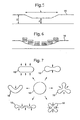
- Fig. 5 shows schematically a constriction, such as in an AV graft 16.
- the normal diameter of the vessel is D
- the constricted diameter is d
- the constriction is applied over a length L.
- the devices of the present invention apply the constriction over an elongate portion of the AV graft 16, for example as shown in Fig. 4(a) .
- the length L is at least twice the original diameter D, and L may even be five to ten or more times the diameter D. The reasons for this are as follows. For a given flow rate Q through the AV graft 16, the viscous losses are proportional to LQ, whereas the turbulent losses are proportional to [(D/d) 2 -I] 2 Q 2 .
- One way to increase the length of the constriction is to provide multiple constriction devices in series along the AV graft 16.
- Another method is to provide a single elongate actuator within the device or multiple actuators disposed along the length of the device.
- Fig. 6 illustrates a further technique for reducing turbulence caused by the constriction, namely by controlling the profile of the constriction such that abrupt transitions in diameter are avoided.
- the profile of the constriction can be controlled by providing a plurality of actuators 120, each of which squeezes the AV graft 16 by a controlled amount.
- the actuators 120 may all be provided within a single constriction device, or each actuator 120 may be provided in a respective constriction device disposed in series along the AV graft 16. Alternatively, a single actuator of a predetermined profile may be used to cause a desired constriction profile.
- FIG. 7 A further technique for favouring viscous dissipation over turbulent dissipation is illustrated with reference to Fig. 7 .
- a transverse cross-section of the unconstricted AV graft is approximately circular as shown in the centre of Fig. 7 .
- Applying an isotopic force around the periphery to squeeze the vessel approximately equally in all directions would tend to reduce the cross-section of the vessel to be a circle of smaller diameter.
- viscous losses are related to the area of the wall of the vessel and hence to the perimeter of the cross-section.
- the perimeter of the lumen can be maintained substantially constant in length while reducing its cross-sectional area.
- Various exemplary resulting shapes are shown in Fig.
- the arrows illustrate the directions and points of application of the squeezing force.
- the devices according to the invention can achieve constrictions of these shapes by a variety of ways, such as having ridged actuators, or a plurality of actuators applying pressure in different directions or surrounding the AV graft 16 by a gel to control the shape of the deformation.
- a further feature of the invention is to adhere the outer surface of the AV graft to the actuator using a glue.
- Bernoulli's equation p + 1 ⁇ 2 ⁇ ⁇ 2 is constant, where p is pressure, ⁇ is viscosity and ⁇ is flow velocity. At a constriction, the flow velocity increases to maintain throughput. At sufficiently high velocity, the pressure given by Bernoulli's equation can become lower than the external pressure on the vessel or even become negative. Thus, at a constriction it is possible for collapse of the vessel to occur because the reduced pressure sucks the walls inwards. The flow of course then stops and the vessel recovers, but vessel collapse is problematic and results in erratic flow conditions.
- Gluing the wall of the AV graft to the actuator prevents collapse by maintaining a minimum diameter of the AV graft, even when constricted.
- AV graft collapse may also be prevented if the constriction is appropriately shaped, as shown in some of the examples in Fig. 7 , to resist further buckling under reduced pressure.
- catheters for extracorporeal flow to and from the AV graft 16 may be provided on opposite sides of the device 20.
- it can be beneficial to increase constriction of the graft during e.g. hemodialysis in order to augment flow through the extracorporeal machine.
- the constriction is still partially applied to alleviate the problems, such as caused by turbulence, whilst keeping the vein matured.
- the device of the invention can also be used with AV fistulas, in which case the flow control device is placed on the artery or vein, just proximal or distal to the fistula, respectively.
- a further preferred aspect of the invention which can be used with any of the above-described embodiments, is to incorporate a flow-measuring device into the variable flow control device 20.
- Figure 3 illustrated an external flow or turbulence measuring device 24, 26, however, according to the present further embodiment, the implanted device incorporates flow-measuring apparatus.
- the flow measured by the device may be communicated, for example, via an antenna 32, to an external device to give a reading of the flow passing through the AV graft.
- the flow measurement may be used internally within the implanted device to control the constriction applied, using a feed-back loop, to regulate the flow.
- a piezo-element emits ultrasound, which is reflected by the flowing blood, the reflected signals being slightly changed in frequency through the Doppler effect, thereby carrying information on velocity which is detected.
- the information on velocity is transmitted from the implanted device 20 via antenna 32 to the external antenna 30 and is then received and displayed by the external control unit 22.
- the flowmeter works on the principle of Faraday's Law of Induction, which states that if a conductor is moved within a magnetic field, a voltage is induced at right angles to the direction of movement in that conductor and at right angles to the magnetic field.
- the voltage generated is proportional to the average velocity of the moving conductor.
- FIG. 8 An example of this embodiment is illustrated in Figure 8 .
- the blood in the vessel 16 acts as the moving conductor.
- a magnetic field B can be applied by an external magnet.
- the magnetic field coming from the external antenna 30 is used. This is advantageous because it eliminates the need to instal magnets or other means of imposing a magnetic field.
- the magnetic field is alternating, in which case a different frequency of B is used than the one used for the control of the flow control device 20.
- the external control unit 22 emits one frequency, for example, for the telemetric control of a motor 36 and for power generation, and another frequency for creating the magnetic field B required for the flow measurement.
- the voltage measuring electrodes 121 are placed perpendicular to B and v, and with a precisely known separation D.
- the EMF generated between the electrodes 121 is sensed by a voltage measuring device 122.
- the voltage measuring device 122 is tuned to the frequency of the externally applied magnetic field B.
- the electrodes 121 can be encapsulated either in the main box of the device 20 or in an auxiliary chamber next to the main box.
Landscapes
- Health & Medical Sciences (AREA)
- Heart & Thoracic Surgery (AREA)
- Life Sciences & Earth Sciences (AREA)
- Vascular Medicine (AREA)
- Veterinary Medicine (AREA)
- Animal Behavior & Ethology (AREA)
- Engineering & Computer Science (AREA)
- Biomedical Technology (AREA)
- Public Health (AREA)
- General Health & Medical Sciences (AREA)
- Cardiology (AREA)
- Surgery (AREA)
- Transplantation (AREA)
- Hematology (AREA)
- Reproductive Health (AREA)
- Gastroenterology & Hepatology (AREA)
- Pulmonology (AREA)
- Medical Informatics (AREA)
- Oral & Maxillofacial Surgery (AREA)
- Molecular Biology (AREA)
- Nuclear Medicine, Radiotherapy & Molecular Imaging (AREA)
- Anesthesiology (AREA)
- Prostheses (AREA)
- External Artificial Organs (AREA)
- Paper (AREA)
- Vehicle Body Suspensions (AREA)
- Flow Control (AREA)
- Measuring Volume Flow (AREA)
- Electrical Discharge Machining, Electrochemical Machining, And Combined Machining (AREA)
- Massaging Devices (AREA)
Claims (25)
- Vorrichtung (20; 120) zum Steuern der Strömung in einem arteriovenösen Transplantat (16, 200), wobei die Vorrichtung umfasst:einen Aktuator (42, 44, 46), um das arteriovenöse Transplantat (16, 200) einstellbar zu verengen;ein drehbares Element (38), um den Aktuator (42, 44, 46) anzutreiben; undeinen Motor (36),dadurch gekennzeichnet, dassdas drehbare Element (38) eine Antriebswelle (38) des Motors (36) umfasst; und dass sie ferner eine Antenne (32) umfasst, um Signale zum Steuern des Aktuators (42, 44, 46) zu empfangen, und wobei der Aktuator (42, 44, 46) ferner eine flexible Membran (46) umfasst, um auf das arteriovenöse Transplantat (16, 200) zu drücken.
- Vorrichtung nach Anspruch 1, bei der der Motor (36) ein elektrischer Mikromotor ist.
- Vorrichtung nach Anspruch 1 oder 2, ferner mit einen Umrichter (34) umfasst, um die Hochfrequenzenergie, die von der Antenne (32) empfangen wird, in Energie für die Leistungsversorgung der Vorrichtung umzurichten, um den Aktuator (42, 44, 46) zu betreiben.
- Vorrichtung nach Anspruch 1, 2 oder 3, ferner mit einem Sensor zum Fühlen des Zustands des Aktuators (42, 44, 46) und zum Senden eines Signals über die Antenne (32), das den Zustand angibt.
- Vorrichtung nach Anspruch 1, 2, 3 oder 4, ferner mit wenigstens einem Sensor, um den Druck und/oder die Durchflussmenge und/oder die Turbulenz zu fühlen und um ein entsprechendes Signal über die Antenne zu senden.
- Vorrichtung nach einem der Ansprüche 1 bis 5, die ferner eine Batterie aufweist.
- Vorrichtung nach einem der Ansprüche 1 bis 6, bei der die flexible Membran (46) Titan enthält.
- Vorrichtung nach einem der Ansprüche 1 bis 7, bei der die Membran (46) wenigstens eine Riffelung (47) aufweist.
- Vorrichtung nach einem der Ansprüche 1 bis 8, bei der der Aktuator (42, 44, 46) so beschaffen ist, dass er das arteriovenöse Transplantat (16, 200) um seinen Querschnittsumfang ungleichmäßig einengt, so dass die Querschnittsfläche des Hohlraums des arteriovenöse Transplantats reduziert werden kann, während die Länge seines Umfangs beibehalten wird.
- Vorrichtung nach einem der Ansprüche 1 bis 9, bei der der Aktuator so geformt ist, dass für die Verengung ein vorgegebenes Profil definiert wird.
- Vorrichtung nach einem der Ansprüche 1 bis 10, die ferner eine Vielzahl der Aktuatoren umfasst.
- Vorrichtung nach einem der Ansprüche 1 bis 11, die das Körpergefäß längs eines lang gestreckten Abschnitts hiervon verengen kann.
- Vorrichtung nach einem der Ansprüche 1 bis 12, die als Ganzes in einen Patienten implantiert werden kann.
- Vorrichtung nach Anspruch 13, die ferner eine implantierbare Hülle (52) aus Titan oder Keramik oder Kunststoff umfasst.
- Kombination aus einer Vorrichtung nach einem der Ansprüche 1 bis 14 und einem implantierbaren arteriovenöse Transplantat (16, 200).
- Kombination nach Anspruch 15, bei der der Aktuator (42, 44, 46) an das Transplantat geklebt ist, um eine unkontrollierte Einschnürung des Transplantats (16, 200) zu verhindern.
- Kombination nach Anspruch 16, bei der die Verengung so geformt ist, dass sie einem weiteren Eindrücken bei verringertem Druck widersteht.
- Kombination nach Anspruch 15,16 oder 17, bei der der Aktuator (42, 44, 46) bei dem einlassseitigen Ende des Transplantats angeordnet ist.
- Kombination nach einem der Ansprüche 15 bis 18, die ferner ein verformbares, aber im Wesentlichen nicht komprimierbares Medium umfasst, das das Transplantat (16, 200) am Ort des Aktuators (42, 44, 46) wenigstens teilweise umgibt.
- Kombination nach einem der Ansprüche 15 bis 19, die einer Vielzahl der Vorrichtungen (120) umfasst, die längs des Transplantats (16, 200) angeordnet sind.
- Kombination nach einem der Ansprüche 15 bis 20, bei der ein Ende des Transplantats (16, 200) mit einer Arterie (10, 202) verbunden werden kann und das andere Ende des Transplantats mit einer Arterie (204) oder mit einer Vene (12) verbunden werden kann.
- Vorrichtung nach einem der Ansprüche 1 bis 14 oder Kombination nach einem der Ansprüche 15 bis 21, die ferner eine Messvorrichtung (24, 26, 121, 122) umfasst, die mit ihr gekoppelt ist, um den Grad der Verengung, die von dem Aktuator (42, 44, 46) ausgeübt wird, zu steuern.
- Vorrichtung oder Kombination nach Anspruch 22, bei der die Messvorrichtung dem Messen der Durchflussmenge und/oder der Turbulenz und/oder des Drucks dient.
- Vorrichtung oder Kombination nach Anspruch 23, bei der die Messvorrichtung eine Doppler-Vorrichtung und/oder eine Phonoangiographieeinrichtung und/oder einen elektromagnetischen Durchflusssensor umfasst.
- Vorrichtung oder Kombination nach Anspruch 22, 23 oder 24, bei der die Messvorrichtung mit der Durchflusssteuervorrichtung einteilig ausgebildet ist.
Priority Applications (2)
| Application Number | Priority Date | Filing Date | Title |
|---|---|---|---|
| DE60014101T DE60014101T3 (de) | 1999-07-19 | 2000-07-19 | Vorrichtung zur durchflusskontrolle |
| EP00949376A EP1200152B2 (de) | 1999-07-19 | 2000-07-19 | Vorrichtung zur durchflusskontrolle |
Applications Claiming Priority (4)
| Application Number | Priority Date | Filing Date | Title |
|---|---|---|---|
| EP99305689 | 1999-07-19 | ||
| EP99305689A EP1072282A1 (de) | 1999-07-19 | 1999-07-19 | Durchflusskontrollvorrichtuing |
| PCT/EP2000/006907 WO2001005463A1 (en) | 1999-07-19 | 2000-07-19 | Flow control method and device |
| EP00949376A EP1200152B2 (de) | 1999-07-19 | 2000-07-19 | Vorrichtung zur durchflusskontrolle |
Publications (3)
| Publication Number | Publication Date |
|---|---|
| EP1200152A1 EP1200152A1 (de) | 2002-05-02 |
| EP1200152B1 EP1200152B1 (de) | 2004-09-22 |
| EP1200152B2 true EP1200152B2 (de) | 2011-08-24 |
Family
ID=8241527
Family Applications (2)
| Application Number | Title | Priority Date | Filing Date |
|---|---|---|---|
| EP99305689A Withdrawn EP1072282A1 (de) | 1999-07-19 | 1999-07-19 | Durchflusskontrollvorrichtuing |
| EP00949376A Expired - Lifetime EP1200152B2 (de) | 1999-07-19 | 2000-07-19 | Vorrichtung zur durchflusskontrolle |
Family Applications Before (1)
| Application Number | Title | Priority Date | Filing Date |
|---|---|---|---|
| EP99305689A Withdrawn EP1072282A1 (de) | 1999-07-19 | 1999-07-19 | Durchflusskontrollvorrichtuing |
Country Status (12)
| Country | Link |
|---|---|
| US (6) | US7128750B1 (de) |
| EP (2) | EP1072282A1 (de) |
| JP (1) | JP2003504166A (de) |
| CN (1) | CN1374877A (de) |
| AT (1) | ATE276790T1 (de) |
| AU (1) | AU6275700A (de) |
| CA (1) | CA2379788A1 (de) |
| DE (1) | DE60014101T3 (de) |
| ES (1) | ES2226885T5 (de) |
| IL (1) | IL147693A0 (de) |
| MX (1) | MXPA02000624A (de) |
| WO (1) | WO2001005463A1 (de) |
Families Citing this family (195)
| Publication number | Priority date | Publication date | Assignee | Title |
|---|---|---|---|---|
| US6254601B1 (en) | 1998-12-08 | 2001-07-03 | Hysterx, Inc. | Methods for occlusion of the uterine arteries |
| EP1072282A1 (de) * | 1999-07-19 | 2001-01-31 | EndoArt S.A. | Durchflusskontrollvorrichtuing |
| US6550482B1 (en) | 2000-04-21 | 2003-04-22 | Vascular Control Systems, Inc. | Methods for non-permanent occlusion of a uterine artery |
| US7223279B2 (en) | 2000-04-21 | 2007-05-29 | Vascular Control Systems, Inc. | Methods for minimally-invasive, non-permanent occlusion of a uterine artery |
| US6635065B2 (en) | 2000-11-16 | 2003-10-21 | Vascular Control Systems, Inc. | Doppler directed suture ligation device and method |
| US6638286B1 (en) | 2000-11-16 | 2003-10-28 | Vascular Control Systems, Inc. | Doppler directed suture ligation device and method |
| US7354444B2 (en) | 2001-03-28 | 2008-04-08 | Vascular Control Systems, Inc. | Occlusion device with deployable paddles for detection and occlusion of blood vessels |
| JP4227415B2 (ja) | 2001-03-28 | 2009-02-18 | ヴァスキュラー・コントロール・システムズ・インコーポレーテッド | 子宮動脈を検知及び結紮する方法及び装置 |
| US6663596B2 (en) | 2001-08-13 | 2003-12-16 | Scimed Life Systems, Inc. | Delivering material to a patient |
| WO2003061488A1 (en) * | 2002-01-22 | 2003-07-31 | Arts Medical S.A. | Coronary inflow occlusion and anastomotic assist device |
| EP1343112A1 (de) * | 2002-03-08 | 2003-09-10 | EndoArt S.A. | Implantierbare Vorrichtung |
| US7207996B2 (en) | 2002-04-04 | 2007-04-24 | Vascular Control Systems, Inc. | Doppler directed suturing and compression device and method |
| US7338433B2 (en) | 2002-08-13 | 2008-03-04 | Allergan, Inc. | Remotely adjustable gastric banding method |
| BR0306183A (pt) | 2002-08-28 | 2004-10-19 | Inamed Medical Products Corp | Dispositivo de enfaixamento gástrico resistente à fadiga |
| US7172603B2 (en) | 2002-11-19 | 2007-02-06 | Vascular Control Systems, Inc. | Deployable constrictor for uterine artery occlusion |
| US20040097961A1 (en) | 2002-11-19 | 2004-05-20 | Vascular Control System | Tenaculum for use with occlusion devices |
| US7404821B2 (en) | 2003-01-30 | 2008-07-29 | Vascular Control Systems, Inc. | Treatment for post partum hemorrhage |
| US7651511B2 (en) | 2003-02-05 | 2010-01-26 | Vascular Control Systems, Inc. | Vascular clamp for caesarian section |
| US7333844B2 (en) | 2003-03-28 | 2008-02-19 | Vascular Control Systems, Inc. | Uterine tissue monitoring device and method |
| US20040249335A1 (en) * | 2003-04-08 | 2004-12-09 | Faul John L. | Implantable arteriovenous shunt device |
| EP1622657B1 (de) | 2003-04-23 | 2011-06-08 | Interrad Medical, Inc. | Dialyseventil |
| US8114044B2 (en) * | 2003-06-06 | 2012-02-14 | Creativasc Medical, Llc | Arteriovenous access valve system and process |
| US20050137614A1 (en) * | 2003-10-08 | 2005-06-23 | Porter Christopher H. | System and method for connecting implanted conduits |
| US7762977B2 (en) | 2003-10-08 | 2010-07-27 | Hemosphere, Inc. | Device and method for vascular access |
| US7325546B2 (en) | 2003-11-20 | 2008-02-05 | Vascular Control Systems, Inc. | Uterine artery occlusion device with cervical receptacle |
| US7686817B2 (en) | 2003-11-25 | 2010-03-30 | Vascular Control Systems, Inc. | Occlusion device for asymmetrical uterine artery anatomy |
| MXPA06008256A (es) | 2004-01-23 | 2007-02-20 | Allergan Inc | Banda gastrica ajustable de una sola pieza que se asegura de manera liberable. |
| ATE444045T1 (de) | 2004-03-08 | 2009-10-15 | Allergan Medical S A | Verschlusssystem für röhrenförmige organe |
| WO2005094257A2 (en) | 2004-03-18 | 2005-10-13 | Inamed Medical Products Corporation | Apparatus and method for volume adjustment of intragastric balloons |
| US7955357B2 (en) | 2004-07-02 | 2011-06-07 | Ellipse Technologies, Inc. | Expandable rod system to treat scoliosis and method of using the same |
| US9706997B2 (en) | 2004-08-27 | 2017-07-18 | Rox Medical, Inc. | Device and method for establishing an artificial arterio-venous fistula |
| US7828814B2 (en) | 2004-08-27 | 2010-11-09 | Rox Medical, Inc. | Device and method for establishing an artificial arterio-venous fistula |
| US20060047337A1 (en) | 2004-08-27 | 2006-03-02 | Brenneman Rodney A | Device and method for establishing an artificial arterio-venous fistula |
| US7875036B2 (en) | 2004-10-27 | 2011-01-25 | Vascular Control Systems, Inc. | Short term treatment for uterine disorder |
| US20060122565A1 (en) * | 2004-11-23 | 2006-06-08 | Kooi Chee C | Switch structures or the like based on a thermoresponsive polymer |
| US8226592B2 (en) * | 2004-12-15 | 2012-07-24 | Rox Medical, Inc. | Method of treating COPD with artificial arterio-venous fistula and flow mediating systems |
| JP4798522B2 (ja) * | 2005-03-08 | 2011-10-19 | 修 松村 | 陰茎の勃起制御方法および陰茎の勃起制御装置 |
| US8251888B2 (en) | 2005-04-13 | 2012-08-28 | Mitchell Steven Roslin | Artificial gastric valve |
| US9642726B2 (en) | 2005-07-25 | 2017-05-09 | Vascular Dynamics, Inc. | Devices and methods for control of blood pressure |
| US9592136B2 (en) | 2005-07-25 | 2017-03-14 | Vascular Dynamics, Inc. | Devices and methods for control of blood pressure |
| US8923972B2 (en) | 2005-07-25 | 2014-12-30 | Vascular Dynamics, Inc. | Elliptical element for blood pressure reduction |
| US20110118773A1 (en) * | 2005-07-25 | 2011-05-19 | Rainbow Medical Ltd. | Elliptical device for treating afterload |
| US9125732B2 (en) | 2005-07-25 | 2015-09-08 | Vascular Dynamics, Inc. | Devices and methods for control of blood pressure |
| US20110077729A1 (en) * | 2009-09-29 | 2011-03-31 | Vascular Dynamics Inc. | Devices and methods for control of blood pressure |
| US8043206B2 (en) | 2006-01-04 | 2011-10-25 | Allergan, Inc. | Self-regulating gastric band with pressure data processing |
| US7798954B2 (en) | 2006-01-04 | 2010-09-21 | Allergan, Inc. | Hydraulic gastric band with collapsible reservoir |
| WO2008008281A2 (en) | 2006-07-07 | 2008-01-17 | Proteus Biomedical, Inc. | Smart parenteral administration system |
| US20080077070A1 (en) * | 2006-08-10 | 2008-03-27 | Kopia Gregory A | Arteriovenous shunt |
| US8246533B2 (en) | 2006-10-20 | 2012-08-21 | Ellipse Technologies, Inc. | Implant system with resonant-driven actuator |
| US20080097249A1 (en) * | 2006-10-20 | 2008-04-24 | Ellipse Technologies, Inc. | External sensing system for gastric restriction devices |
| US7862502B2 (en) | 2006-10-20 | 2011-01-04 | Ellipse Technologies, Inc. | Method and apparatus for adjusting a gastrointestinal restriction device |
| US9549808B2 (en) | 2006-12-07 | 2017-01-24 | Stanley Batiste | Bypass configuration and method of construction |
| US9603695B2 (en) | 2006-12-07 | 2017-03-28 | Stanley Batiste | Bypass vascular graft |
| US9039758B2 (en) * | 2006-12-07 | 2015-05-26 | Stanley Batiste | Bypass vascular graft |
| EP1998054B1 (de) * | 2007-05-24 | 2014-08-13 | Parker Origa Holding AG | Pneumatikzylinder mit einer selbsteinstellenden Endlagendämpfung und entsprechendes Verfahren |
| WO2009055733A1 (en) | 2007-10-25 | 2009-04-30 | Proteus Biomedical, Inc. | Fluid transfer port information system |
| US20090112263A1 (en) | 2007-10-30 | 2009-04-30 | Scott Pool | Skeletal manipulation system |
| WO2009067463A1 (en) * | 2007-11-19 | 2009-05-28 | Proteus Biomedical, Inc. | Body-associated fluid transport structure evaluation devices |
| WO2009086548A1 (en) * | 2007-12-31 | 2009-07-09 | C.R. Bard, Inc. | Vascular graft prosthesis with selective flow reduction |
| US20110295181A1 (en) | 2008-03-05 | 2011-12-01 | Hemosphere, Inc. | Implantable and removable customizable body conduit |
| WO2009120764A2 (en) | 2008-03-25 | 2009-10-01 | Ellipse Technologies, Inc. | Systems and methods for adjusting an annuloplasty ring with an integrated magnetic drive |
| US11202707B2 (en) | 2008-03-25 | 2021-12-21 | Nuvasive Specialized Orthopedics, Inc. | Adjustable implant system |
| CA2727001A1 (en) | 2008-06-11 | 2009-12-17 | Allergan, Inc. | Implantable pump system |
| US20100056978A1 (en) * | 2008-08-27 | 2010-03-04 | Lindsay Machan | Externally adjustable blood flow valve |
| ES2725524T3 (es) | 2008-09-26 | 2019-09-24 | Vascular Dynamics Inc | Dispositivos y métodos para controlar la presión arterial |
| WO2010042493A1 (en) | 2008-10-06 | 2010-04-15 | Allergan, Inc. | Mechanical gastric band with cushions |
| US20100185049A1 (en) | 2008-10-22 | 2010-07-22 | Allergan, Inc. | Dome and screw valves for remotely adjustable gastric banding systems |
| US8382756B2 (en) | 2008-11-10 | 2013-02-26 | Ellipse Technologies, Inc. | External adjustment device for distraction device |
| US8197490B2 (en) | 2009-02-23 | 2012-06-12 | Ellipse Technologies, Inc. | Non-invasive adjustable distraction system |
| US9622792B2 (en) | 2009-04-29 | 2017-04-18 | Nuvasive Specialized Orthopedics, Inc. | Interspinous process device and method |
| US8332020B2 (en) | 2010-02-01 | 2012-12-11 | Proteus Digital Health, Inc. | Two-wrist data gathering system |
| BR112012019212A2 (pt) | 2010-02-01 | 2017-06-13 | Proteus Digital Health Inc | sistema de coleta de dados |
| US8678993B2 (en) | 2010-02-12 | 2014-03-25 | Apollo Endosurgery, Inc. | Remotely adjustable gastric banding system |
| US8758221B2 (en) | 2010-02-24 | 2014-06-24 | Apollo Endosurgery, Inc. | Source reservoir with potential energy for remotely adjustable gastric banding system |
| US8764624B2 (en) | 2010-02-25 | 2014-07-01 | Apollo Endosurgery, Inc. | Inductively powered remotely adjustable gastric banding system |
| US8840541B2 (en) | 2010-02-25 | 2014-09-23 | Apollo Endosurgery, Inc. | Pressure sensing gastric banding system |
| US8939888B2 (en) | 2010-04-28 | 2015-01-27 | Apollo Endosurgery, Inc. | Method and system for determining the pressure of a fluid in a syringe, an access port, a catheter, and a gastric band |
| US9028394B2 (en) | 2010-04-29 | 2015-05-12 | Apollo Endosurgery, Inc. | Self-adjusting mechanical gastric band |
| US9044298B2 (en) | 2010-04-29 | 2015-06-02 | Apollo Endosurgery, Inc. | Self-adjusting gastric band |
| US20110270024A1 (en) | 2010-04-29 | 2011-11-03 | Allergan, Inc. | Self-adjusting gastric band having various compliant components |
| US20110270025A1 (en) | 2010-04-30 | 2011-11-03 | Allergan, Inc. | Remotely powered remotely adjustable gastric band system |
| US9226840B2 (en) | 2010-06-03 | 2016-01-05 | Apollo Endosurgery, Inc. | Magnetically coupled implantable pump system and method |
| US8517915B2 (en) | 2010-06-10 | 2013-08-27 | Allergan, Inc. | Remotely adjustable gastric banding system |
| US10010439B2 (en) | 2010-06-13 | 2018-07-03 | Synerz Medical, Inc. | Intragastric device for treating obesity |
| US10420665B2 (en) | 2010-06-13 | 2019-09-24 | W. L. Gore & Associates, Inc. | Intragastric device for treating obesity |
| US8628554B2 (en) | 2010-06-13 | 2014-01-14 | Virender K. Sharma | Intragastric device for treating obesity |
| US9526648B2 (en) | 2010-06-13 | 2016-12-27 | Synerz Medical, Inc. | Intragastric device for treating obesity |
| US9248043B2 (en) | 2010-06-30 | 2016-02-02 | Ellipse Technologies, Inc. | External adjustment device for distraction device |
| WO2012021378A2 (en) | 2010-08-09 | 2012-02-16 | Ellipse Technologies, Inc. | Maintenance feature in magnetic implant |
| US8698373B2 (en) | 2010-08-18 | 2014-04-15 | Apollo Endosurgery, Inc. | Pare piezo power with energy recovery |
| US9211207B2 (en) | 2010-08-18 | 2015-12-15 | Apollo Endosurgery, Inc. | Power regulated implant |
| US20120059216A1 (en) | 2010-09-07 | 2012-03-08 | Allergan, Inc. | Remotely adjustable gastric banding system |
| CN101919723A (zh) * | 2010-09-08 | 2010-12-22 | 中南大学 | 外科手术用动物血管血流量实时控制装置 |
| US8961393B2 (en) | 2010-11-15 | 2015-02-24 | Apollo Endosurgery, Inc. | Gastric band devices and drive systems |
| WO2012104848A1 (en) * | 2011-02-03 | 2012-08-09 | Geva Sol Bv | Controllable flow regulator system |
| NL2007134C2 (en) * | 2011-02-03 | 2012-08-09 | Geva Sol B V | Controllable flow regulator system. |
| WO2012112396A2 (en) | 2011-02-14 | 2012-08-23 | Ellipse Technologies, Inc. | Device and method for treating fractured bones |
| ES2540957T3 (es) * | 2011-03-16 | 2015-07-15 | Duke University | Implante arteriovenoso para hemodiálisis con paredes posterior y lateral resistentes a la perforación |
| US8541069B2 (en) * | 2011-04-11 | 2013-09-24 | United Technologies Corporation | Method of guided non-line of sight coating |
| US8725435B2 (en) | 2011-04-13 | 2014-05-13 | Apollo Endosurgery, Inc. | Syringe-based leak detection system |
| CN102302387B (zh) * | 2011-06-17 | 2014-05-28 | 中国人民解放军第二军医大学 | 压力流量可调性中小口径人工血管 |
| EP2739327B1 (de) | 2011-08-01 | 2019-07-24 | Laminate Medical Technologies Ltd | Gefässformungsvorrichtungen |
| WO2013018133A1 (en) * | 2011-08-02 | 2013-02-07 | J.Morita Manufacturing Corporation | Pulmonary artery band |
| EP3165245B1 (de) | 2011-08-02 | 2019-02-20 | Medtronic, Inc. | Hämodialysesystem mit einem durchflussweg mit gesteuertem nachgiebigem volumen |
| EP2753376B1 (de) | 2011-09-06 | 2015-07-01 | Hemosphere Inc. | Gefässzugangssystem mit einem verbinder |
| US10743794B2 (en) | 2011-10-04 | 2020-08-18 | Nuvasive Specialized Orthopedics, Inc. | Devices and methods for non-invasive implant length sensing |
| US10016220B2 (en) | 2011-11-01 | 2018-07-10 | Nuvasive Specialized Orthopedics, Inc. | Adjustable magnetic devices and methods of using same |
| US8876694B2 (en) | 2011-12-07 | 2014-11-04 | Apollo Endosurgery, Inc. | Tube connector with a guiding tip |
| US9163623B2 (en) | 2011-12-08 | 2015-10-20 | Carefusion 303, Inc. | System and method for improved flow uniformity in a peristaltic pump mechanism |
| US8961394B2 (en) | 2011-12-20 | 2015-02-24 | Apollo Endosurgery, Inc. | Self-sealing fluid joint for use with a gastric band |
| WO2013096548A1 (en) * | 2011-12-23 | 2013-06-27 | Volcano Corporation | Methods and apparatus for regulating blood pressure |
| US8968233B2 (en) | 2012-02-03 | 2015-03-03 | Medtronic Vascular, Inc. | Arteriovenous shunt having a moveable valve |
| AU2013298145B2 (en) | 2012-08-01 | 2017-11-23 | Laminate Medical Technologies Ltd. | Apparatus for configuring an arteriovenous fistula |
| US9339636B1 (en) | 2012-09-06 | 2016-05-17 | Mubashir H Khan | Subcutaneous fluid pump |
| CN104902854B (zh) | 2012-10-29 | 2017-10-03 | 诺威适骨科专科公司 | 用于治疗膝盖关节炎的可调节装置 |
| US9713666B2 (en) | 2013-01-09 | 2017-07-25 | Medtronic, Inc. | Recirculating dialysate fluid circuit for blood measurement |
| US11154648B2 (en) | 2013-01-09 | 2021-10-26 | Medtronic, Inc. | Fluid circuits for sorbent cartridge with sensors |
| US9623164B2 (en) | 2013-02-01 | 2017-04-18 | Medtronic, Inc. | Systems and methods for multifunctional volumetric fluid control |
| US10010663B2 (en) | 2013-02-01 | 2018-07-03 | Medtronic, Inc. | Fluid circuit for delivery of renal replacement therapies |
| US10850016B2 (en) | 2013-02-01 | 2020-12-01 | Medtronic, Inc. | Modular fluid therapy system having jumpered flow paths and systems and methods for cleaning and disinfection |
| US10751094B2 (en) | 2013-10-10 | 2020-08-25 | Nuvasive Specialized Orthopedics, Inc. | Adjustable spinal implant |
| US10537875B2 (en) | 2013-11-26 | 2020-01-21 | Medtronic, Inc. | Precision recharging of sorbent materials using patient and session data |
| US9884145B2 (en) | 2013-11-26 | 2018-02-06 | Medtronic, Inc. | Parallel modules for in-line recharging of sorbents using alternate duty cycles |
| US10682453B2 (en) | 2013-12-20 | 2020-06-16 | Merit Medical Systems, Inc. | Vascular access system with reinforcement member |
| US10123896B2 (en) | 2014-03-06 | 2018-11-13 | Mayo Foundation For Medical Education And Research | Apparatus and methods of inducing weight loss using blood flow control |
| JP6636010B2 (ja) | 2014-04-25 | 2020-01-29 | クリエイティヴァスク メディカル コーポレイション | 磁力駆動型動静脈アクセスバルブシステム及びそれに関連する方法 |
| CN111345867A (zh) | 2014-04-28 | 2020-06-30 | 诺威适骨科专科公司 | 遥控装置 |
| US9980813B2 (en) | 2014-04-28 | 2018-05-29 | Cook Medical Technologies Llc | Selective fluid barrier valve device and method of treatment |
| US9561320B2 (en) | 2014-06-05 | 2017-02-07 | Cook Medical Technologies Llc | Device for promoting fistula patency and method |
| EP2952142B1 (de) | 2014-06-06 | 2017-09-06 | Cook Medical Technologies LLC | Vorrichtung zur ausbildung einer fistel zwischen blutgefässen |
| JP6326995B2 (ja) * | 2014-06-12 | 2018-05-23 | ニプロ株式会社 | 血流量調節装置 |
| US10172991B2 (en) | 2014-06-24 | 2019-01-08 | Medtronic, Inc. | Modular dialysate regeneration assembly |
| US10357757B2 (en) | 2014-06-24 | 2019-07-23 | Medtronic, Inc. | Stacked sorbent assembly |
| US10667931B2 (en) | 2014-07-20 | 2020-06-02 | Restore Medical Ltd. | Pulmonary artery implant apparatus and methods of use thereof |
| US10039552B2 (en) * | 2014-10-28 | 2018-08-07 | Cook Medical Technologies Llc | Magnetically actuated gating devices, systems, kits, and methods |
| KR102346227B1 (ko) * | 2014-11-19 | 2021-12-31 | 삼성전자주식회사 | 극자외선 광 생성 장치, 시스템 및 극자외선 광 생성 장치의 사용 방법 |
| EP4005515B1 (de) | 2014-12-26 | 2024-07-24 | NuVasive Specialized Orthopedics, Inc. | Systeme zur distraktion |
| US10238427B2 (en) | 2015-02-19 | 2019-03-26 | Nuvasive Specialized Orthopedics, Inc. | Systems and methods for vertebral adjustment |
| JP6495062B2 (ja) * | 2015-03-20 | 2019-04-03 | 国立大学法人東北大学 | 医療用能動クリップ |
| US9655777B2 (en) * | 2015-04-07 | 2017-05-23 | Novartis Ag | System and method for diagphragm pumping using heating element |
| US10022252B2 (en) | 2015-06-10 | 2018-07-17 | Cook Medical Technologies Llc | Spiral blood flow device with diameter independent helix angle |
| WO2017040366A1 (en) * | 2015-08-28 | 2017-03-09 | University Of Cincinnati | Arteriovenous fistula implant effective for inducing laminar blood flow |
| WO2017066774A1 (en) | 2015-10-16 | 2017-04-20 | Nuvasive Specialized Orthopedics, Inc. | Adjustable devices for treating arthritis of the knee |
| JP6953409B2 (ja) | 2015-12-10 | 2021-10-27 | ニューベイシブ スペシャライズド オーソペディックス,インコーポレイテッド | 伸延デバイス用の外部調整デバイス |
| DK3407812T3 (da) | 2016-01-28 | 2020-09-21 | Nuvasive Specialized Orthopedics Inc | System til knogletransport |
| US10779980B2 (en) | 2016-04-27 | 2020-09-22 | Synerz Medical, Inc. | Intragastric device for treating obesity |
| US11771434B2 (en) | 2016-09-28 | 2023-10-03 | Restore Medical Ltd. | Artery medical apparatus and methods of use thereof |
| US10499920B2 (en) | 2016-11-10 | 2019-12-10 | Merit Medical Systems, Inc. | Anchor device for vascular anastomosis |
| US10981148B2 (en) | 2016-11-29 | 2021-04-20 | Medtronic, Inc. | Zirconium oxide module conditioning |
| US11383072B2 (en) | 2017-01-12 | 2022-07-12 | Merit Medical Systems, Inc. | Methods and systems for selection and use of connectors between conduits |
| US10610633B2 (en) * | 2017-01-23 | 2020-04-07 | Mohammed Ibn khayat Zougari | Contactless actuation for valve implant |
| WO2018140306A1 (en) | 2017-01-25 | 2018-08-02 | Merit Medical Systems, Inc. | Methods and systems for facilitating laminar flow between conduits |
| WO2018164945A1 (en) | 2017-03-06 | 2018-09-13 | Merit Medical Systems, Inc. | Vascular access assembly declotting systems and methods |
| WO2018175850A1 (en) | 2017-03-24 | 2018-09-27 | Merit Medical Systems, Inc. | Subcutaneous vascular assemblies for improving blood flow and related devices and methods |
| CN110691554B (zh) | 2017-06-05 | 2022-11-01 | 恢复医疗有限公司 | 双壁固定长度的支架状设备及其使用方法 |
| US10960381B2 (en) | 2017-06-15 | 2021-03-30 | Medtronic, Inc. | Zirconium phosphate disinfection recharging and conditioning |
| US11179543B2 (en) | 2017-07-14 | 2021-11-23 | Merit Medical Systems, Inc. | Releasable conduit connectors |
| US11911585B2 (en) | 2017-07-20 | 2024-02-27 | Merit Medical Systems, Inc. | Methods and systems for coupling conduits |
| US11058581B2 (en) | 2017-07-20 | 2021-07-13 | Shifamed Holdings, Llc | Adjustable flow glaucoma shunts and methods for making and using same |
| US11166849B2 (en) | 2017-07-20 | 2021-11-09 | Shifamed Holdings, Llc | Adjustable flow glaucoma shunts and methods for making and using same |
| DE102017120569A1 (de) * | 2017-09-07 | 2019-03-07 | Aesculap Ag | Vorrichtung zum sterilisationsparameterabhängigen mechanischen Betätigen oder Aktivieren von Funktionseinheiten |
| US10595874B2 (en) | 2017-09-21 | 2020-03-24 | W. L. Gore & Associates, Inc. | Multiple inflation endovascular medical device |
| CN107714127A (zh) * | 2017-09-26 | 2018-02-23 | 中国人民解放军总医院 | 植入式可控血管闭锁装置 |
| CN107669304A (zh) * | 2017-09-26 | 2018-02-09 | 中国人民解放军总医院 | 埋入式可控血管闭锁装置 |
| CN107714128A (zh) * | 2017-09-26 | 2018-02-23 | 中国人民解放军总医院 | 埋入式智能可控血管闭锁装置 |
| JP2019074429A (ja) * | 2017-10-17 | 2019-05-16 | 株式会社ジェイ・エム・エス | 超音波流量計及び血液浄化装置 |
| WO2019089569A1 (en) | 2017-10-31 | 2019-05-09 | Merit Medical Systems, Inc. | Subcutaneous vascular assemblies for improving blood flow and related devices and methods |
| JP7090156B2 (ja) | 2017-12-01 | 2022-06-23 | シー・アール・バード・インコーポレーテッド | 人工医療デバイス |
| CN108465134B (zh) * | 2018-02-07 | 2020-06-26 | 温州市中心医院 | 一种血液透析上肢内痿固定装置 |
| DE102018114856A1 (de) * | 2018-06-20 | 2019-12-24 | Fresenius Medical Care Deutschland Gmbh | Implantat zur Bereitstellung eines Shunts mit verstellbarem Durchfluss |
| US12285552B2 (en) | 2018-08-14 | 2025-04-29 | Mozarc Medical Us Llc | Precision dialysis therapy based on sorbent effluent analysis |
| US11213616B2 (en) | 2018-08-24 | 2022-01-04 | Medtronic, Inc. | Recharge solution for zirconium phosphate |
| WO2020150663A1 (en) | 2019-01-18 | 2020-07-23 | Shifamed Holdings, Llc | Adjustable flow glaucoma shunts and methods for making and using same |
| JP7575385B2 (ja) * | 2019-02-01 | 2024-10-29 | ダブリュ.エル.ゴア アンド アソシエイツ,インコーポレイティド | 遠隔調整可能な機構ならびに関連するシステム及び方法 |
| US12533500B2 (en) * | 2019-06-18 | 2026-01-27 | Shifamed Holdings, Llc | Adjustable interatrial shunts and associated systems and methods |
| WO2021034537A1 (en) | 2019-08-22 | 2021-02-25 | Edwards Lifesciences Corporation | Puncture needles |
| US11517477B2 (en) | 2019-10-10 | 2022-12-06 | Shifamed Holdings, Llc | Adjustable flow glaucoma shunts and associated systems and methods |
| CN114727836B (zh) | 2019-11-14 | 2026-01-09 | 爱德华兹生命科学公司 | 经导管的医疗植入物递送 |
| CN115379818A (zh) | 2020-01-23 | 2022-11-22 | 施菲姆德控股有限责任公司 | 可调节流量的青光眼分流器及相关系统和方法 |
| EP4103248B1 (de) * | 2020-02-11 | 2025-08-20 | Forcella, Mauro Fausto Angelo | Innovative vorrichtung für gefässzugang bei einer dialysebehandlung |
| EP4103117A4 (de) | 2020-02-14 | 2024-03-20 | Shifamed Holdings, LLC | Rangiersysteme mit rotationsbasierten durchflusssteuerungsvorrichtungen und zugehörige systeme und verfahren |
| US11737920B2 (en) | 2020-02-18 | 2023-08-29 | Shifamed Holdings, Llc | Adjustable flow glaucoma shunts having non-linearly arranged flow control elements, and associated systems and methods |
| JP7743435B2 (ja) | 2020-04-16 | 2025-09-24 | シファメド・ホールディングス・エルエルシー | 調整可能な緑内障治療デバイス並びに関連付けられたシステム及び方法 |
| US12544010B2 (en) | 2020-10-28 | 2026-02-10 | Shifamed Holdings, Llc | Systems and methods for electrical monitoring of implantable devices |
| EP4578483A3 (de) * | 2021-01-17 | 2025-10-01 | Inspire M.D Ltd | Shunts mit blutflussindikatoren |
| US11865283B2 (en) | 2021-01-22 | 2024-01-09 | Shifamed Holdings, Llc | Adjustable shunting systems with plate assemblies, and associated systems and methods |
| US12527942B2 (en) | 2021-02-01 | 2026-01-20 | Edwards Lifesciences Corporation | Pulmonary vein shunting |
| JP7576884B2 (ja) | 2021-03-25 | 2024-11-01 | インスパイア エム.ディー リミテッド | 動脈系と静脈系の間で血液をシャントする装置 |
| US12569601B2 (en) | 2021-04-07 | 2026-03-10 | Mozarc Medical Us Llc | Increased operational capabilities of a dialysis system |
| US20220362537A1 (en) * | 2021-05-13 | 2022-11-17 | Farajallah Mounir Hanna al-kass | Flow modulation devices and methods of use with a hemodyalisys fistula or a graft |
| US12397093B2 (en) | 2021-05-18 | 2025-08-26 | Mozarc Medical Us Llc | Sorbent cartridge designs |
| CN114682471B (zh) * | 2022-03-08 | 2022-11-29 | 吉林大学 | 一种超声控制装置及检测系统 |
| KR102873786B1 (ko) * | 2022-03-28 | 2025-10-20 | 고려대학교 산학협력단 | 혈류조절용 혈관클립 |
| EP4295786A1 (de) | 2022-06-24 | 2023-12-27 | Fondation EspeRare | Implantierbare medizinische vorrichtung zur steuerung der strömung in einem körpergefäss |
| CN120176785B (zh) * | 2025-05-21 | 2025-09-02 | 内蒙古科技大学 | 一种电磁激励的高温液态金属节流流量测量系统及方法 |
Citations (5)
| Publication number | Priority date | Publication date | Assignee | Title |
|---|---|---|---|---|
| US3750194A (en) † | 1971-03-16 | 1973-08-07 | Fairchild Industries | Apparatus and method for reversibly closing a natural or implanted body passage |
| US4146029A (en) † | 1974-04-23 | 1979-03-27 | Ellinwood Jr Everett H | Self-powered implanted programmable medication system and method |
| WO2000009047A1 (en) † | 1998-08-13 | 2000-02-24 | Obtech Medical Ag | Food intake restriction device |
| WO2000009048A1 (en) † | 1998-08-13 | 2000-02-24 | Obtech Medical Ag | Food intake restriction device |
| WO2000015158A1 (fr) † | 1998-09-14 | 2000-03-23 | Sofradim Production | Dispositif de constriction gastrique |
Family Cites Families (34)
| Publication number | Priority date | Publication date | Assignee | Title |
|---|---|---|---|---|
| SE344275B (de) | 1966-02-10 | 1972-04-10 | R Gruenert | |
| US3538917A (en) | 1968-04-12 | 1970-11-10 | Robert G Selker | Balloon occlusion clip |
| FR2086747A5 (de) | 1970-04-07 | 1971-12-31 | Cotton De Bennetot M | |
| US3810259A (en) | 1971-01-25 | 1974-05-14 | Fairchild Industries | Implantable urinary control apparatus |
| US3692027A (en) * | 1971-04-23 | 1972-09-19 | Everett H Ellinwood Jr | Implanted medication dispensing device and method |
| US3863622A (en) | 1973-01-09 | 1975-02-04 | Robert Enno Buuck | Incontinence system and methods of implanting and using same |
| US4118805A (en) | 1977-02-28 | 1978-10-10 | Codman & Shurtleff, Inc. | Artificial sphincter |
| US4256093A (en) | 1978-10-12 | 1981-03-17 | The United States Of America As Represented By The Administrator Of The National Aeronautics And Space Administration | Prosthetic urinary sphincter |
| US4390019A (en) * | 1979-02-28 | 1983-06-28 | Leveen Harry H | Blood vessel clamp |
| US4256094A (en) | 1979-06-18 | 1981-03-17 | Kapp John P | Arterial pressure control system |
| US4392019A (en) * | 1980-12-19 | 1983-07-05 | Independent Broadcasting Authority | Surround sound system |
| WO1986001395A1 (en) | 1984-09-05 | 1986-03-13 | Intra Optics Laboratories Pty. Ltd. | Control of blood flow |
| WO1988000455A1 (en) * | 1986-07-17 | 1988-01-28 | Quotidian No. 100 Pty. Limited | Control of blood flow to an organ |
| DE4037043A1 (de) * | 1990-11-19 | 1992-05-21 | Ulrich Dr Med Hanack | In lebewesen implantierbarer bimetallenergiewandler |
| US5470892A (en) * | 1992-05-01 | 1995-11-28 | Innotech, Inc. | Polymerizable resin for forming clear, hard plastics |
| US5601604A (en) * | 1993-05-27 | 1997-02-11 | Inamed Development Co. | Universal gastric band |
| DE69507955T2 (de) | 1994-07-11 | 1999-08-12 | Dacomed Corp., Minneapolis, Minn. | Prosthetische verschlusseinrichtung |
| US5509888A (en) * | 1994-07-26 | 1996-04-23 | Conceptek Corporation | Controller valve device and method |
| DE4427583C2 (de) * | 1994-08-04 | 1999-04-29 | Und Wilkau Reinhard Von Lieres | Shunt-Ventil für ein Drainagesystem zur Therapie des Hydrocephalus |
| US5591217A (en) | 1995-01-04 | 1997-01-07 | Plexus, Inc. | Implantable stimulator with replenishable, high value capacitive power source and method therefor |
| DE19508129C2 (de) * | 1995-03-08 | 1997-02-13 | Jan Dr Med Menke | Blutdurchflußeinstelleinrichtung zur wahlweisen externen Verengung und Erweiterung des Blutdurchflußquerschnittes eines Blutgefäßes |
| US5571121A (en) * | 1995-03-28 | 1996-11-05 | Heifetz; Milton D. | Atraumatic clamp for temporary occlusion of blood vessels |
| US5662711A (en) * | 1995-06-07 | 1997-09-02 | Douglas; William | Flow adjustable artery shunt |
| US5771903A (en) | 1995-09-22 | 1998-06-30 | Kirk Promotions Limited | Surgical method for reducing the food intake of a patient |
| US5847447A (en) | 1996-07-09 | 1998-12-08 | Ambient Corporation | Capcitively coupled bi-directional data and power transmission system |
| US5879320A (en) * | 1996-12-23 | 1999-03-09 | Cazenave; Craig Richard | Implantable vascular device |
| US5938669A (en) | 1997-05-07 | 1999-08-17 | Klasamed S.A. | Adjustable gastric banding device for contracting a patient's stomach |
| JPH1176248A (ja) * | 1997-09-11 | 1999-03-23 | Terumo Corp | 血流量調節装置 |
| US6074341A (en) | 1998-06-09 | 2000-06-13 | Timm Medical Technologies, Inc. | Vessel occlusive apparatus and method |
| US6296622B1 (en) * | 1998-12-21 | 2001-10-02 | Micrus Corporation | Endoluminal device delivery system using axially recovering shape memory material |
| US6531964B1 (en) | 1999-02-25 | 2003-03-11 | Motorola, Inc. | Passive remote control system |
| US6231551B1 (en) | 1999-03-01 | 2001-05-15 | Coaxia, Inc. | Partial aortic occlusion devices and methods for cerebral perfusion augmentation |
| EP1072282A1 (de) | 1999-07-19 | 2001-01-31 | EndoArt S.A. | Durchflusskontrollvorrichtuing |
| US6470892B1 (en) * | 2000-02-10 | 2002-10-29 | Obtech Medical Ag | Mechanical heartburn and reflux treatment |
-
1999
- 1999-07-19 EP EP99305689A patent/EP1072282A1/de not_active Withdrawn
-
2000
- 2000-07-19 EP EP00949376A patent/EP1200152B2/de not_active Expired - Lifetime
- 2000-07-19 CN CN00813075A patent/CN1374877A/zh active Pending
- 2000-07-19 US US10/031,469 patent/US7128750B1/en not_active Expired - Lifetime
- 2000-07-19 ES ES00949376T patent/ES2226885T5/es not_active Expired - Lifetime
- 2000-07-19 AU AU62757/00A patent/AU6275700A/en not_active Abandoned
- 2000-07-19 IL IL14769300A patent/IL147693A0/xx unknown
- 2000-07-19 DE DE60014101T patent/DE60014101T3/de not_active Expired - Lifetime
- 2000-07-19 JP JP2001510547A patent/JP2003504166A/ja active Pending
- 2000-07-19 CA CA002379788A patent/CA2379788A1/en not_active Abandoned
- 2000-07-19 MX MXPA02000624A patent/MXPA02000624A/es unknown
- 2000-07-19 WO PCT/EP2000/006907 patent/WO2001005463A1/en not_active Ceased
- 2000-07-19 AT AT00949376T patent/ATE276790T1/de not_active IP Right Cessation
-
2006
- 2006-10-26 US US11/586,886 patent/US8079974B2/en not_active Expired - Fee Related
-
2011
- 2011-01-31 US US13/018,322 patent/US20110130702A1/en not_active Abandoned
- 2011-01-31 US US13/018,270 patent/US8932247B2/en not_active Expired - Fee Related
- 2011-02-28 US US13/036,358 patent/US8506517B2/en not_active Expired - Fee Related
- 2011-07-15 US US13/184,340 patent/US8821430B2/en not_active Expired - Fee Related
Patent Citations (5)
| Publication number | Priority date | Publication date | Assignee | Title |
|---|---|---|---|---|
| US3750194A (en) † | 1971-03-16 | 1973-08-07 | Fairchild Industries | Apparatus and method for reversibly closing a natural or implanted body passage |
| US4146029A (en) † | 1974-04-23 | 1979-03-27 | Ellinwood Jr Everett H | Self-powered implanted programmable medication system and method |
| WO2000009047A1 (en) † | 1998-08-13 | 2000-02-24 | Obtech Medical Ag | Food intake restriction device |
| WO2000009048A1 (en) † | 1998-08-13 | 2000-02-24 | Obtech Medical Ag | Food intake restriction device |
| WO2000015158A1 (fr) † | 1998-09-14 | 2000-03-23 | Sofradim Production | Dispositif de constriction gastrique |
Also Published As
| Publication number | Publication date |
|---|---|
| WO2001005463A1 (en) | 2001-01-25 |
| MXPA02000624A (es) | 2003-07-21 |
| CN1374877A (zh) | 2002-10-16 |
| EP1200152B1 (de) | 2004-09-22 |
| US8506517B2 (en) | 2013-08-13 |
| US8079974B2 (en) | 2011-12-20 |
| US7128750B1 (en) | 2006-10-31 |
| CA2379788A1 (en) | 2001-01-25 |
| US20110144670A1 (en) | 2011-06-16 |
| AU6275700A (en) | 2001-02-05 |
| US20110130702A1 (en) | 2011-06-02 |
| US20070055296A1 (en) | 2007-03-08 |
| EP1072282A1 (de) | 2001-01-31 |
| DE60014101T2 (de) | 2005-10-06 |
| US20110270288A1 (en) | 2011-11-03 |
| DE60014101T3 (de) | 2012-02-09 |
| ATE276790T1 (de) | 2004-10-15 |
| IL147693A0 (en) | 2002-08-14 |
| DE60014101D1 (de) | 2004-10-28 |
| US8932247B2 (en) | 2015-01-13 |
| ES2226885T5 (es) | 2012-01-05 |
| ES2226885T3 (es) | 2005-04-01 |
| US20110130701A1 (en) | 2011-06-02 |
| EP1200152A1 (de) | 2002-05-02 |
| JP2003504166A (ja) | 2003-02-04 |
| US8821430B2 (en) | 2014-09-02 |
Similar Documents
| Publication | Publication Date | Title |
|---|---|---|
| EP1200152B1 (de) | Vorrichtung zur durchflusskontrolle | |
| US20230277836A1 (en) | Sensor device for sensing at least one functional value of a medical device and a method for operating the sensor device | |
| JP4011631B2 (ja) | 圧力感応ステント | |
| EP2967954B1 (de) | Einschränkungsvorrichtung | |
| US6398734B1 (en) | Ultrasonic sensors for monitoring the condition of flow through a cardiac valve | |
| EP1462133A2 (de) | Verfahren und Vorrichtung zum Einstellen der Länge von einer Einlaufleitung in einer Herzunterstützungseinrichtung | |
| US20050095351A1 (en) | Method, apparatus and system for nanovibration coating and biofilm prevention associated with medical devices | |
| US20060235349A1 (en) | Implantable anti-clogging device for maintenance of cerebrospinal fluid shunt patency | |
| Weiss et al. | A completely implanted left ventricular assist device: chronic in vivo testing | |
| WO2022119509A1 (en) | Programmable drainage system enabling invasive discharge of excess fluid in the body | |
| CN112915310A (zh) | 体内植入式蠕动泵、蠕动泵控制器及体液转运系统 | |
| EP4378495A3 (de) | Extrakorporales lebensunterstützungssystem | |
| JP4242078B2 (ja) | 人工排尿装置 | |
| CN208611415U (zh) | 引流系统 | |
| CN113331808A (zh) | 一种心内科介入术后肢体护理装置 | |
| CN118698020B (zh) | 一种具有体外呼吸腔的主动脉外反搏器械 | |
| CA2105935C (en) | Electrohydraulic ventricular assist device | |
| CN121987866A (zh) | 一种集成实时压力监测功能的胸腹腔引流导管及其监测方法 | |
| EP4295786A1 (de) | Implantierbare medizinische vorrichtung zur steuerung der strömung in einem körpergefäss | |
| CN121288056A (zh) | 一种多功能透析导管及透析系统 | |
| CN120132102A (zh) | 一种血液透析用外周血管导管组件 | |
| CN121001667A (zh) | 使用具有间歇性压力脉冲注入的静态真空源的脉动抽吸系统 | |
| JPS60135044A (ja) | ドレナ−ジチユ−ブ装置 | |
| AU2007229361A1 (en) | Blood Pump with an Ultrasonic Transducer |
Legal Events
| Date | Code | Title | Description |
|---|---|---|---|
| PUAI | Public reference made under article 153(3) epc to a published international application that has entered the european phase |
Free format text: ORIGINAL CODE: 0009012 |
|
| 17P | Request for examination filed |
Effective date: 20020215 |
|
| AK | Designated contracting states |
Kind code of ref document: A1 Designated state(s): AT BE CH CY DE DK ES FI FR GB GR IE IT LI LU MC NL PT SE |
|
| AX | Request for extension of the european patent |
Free format text: AL;LT;LV;MK;RO;SI |
|
| 17Q | First examination report despatched |
Effective date: 20020529 |
|
| GRAP | Despatch of communication of intention to grant a patent |
Free format text: ORIGINAL CODE: EPIDOSNIGR1 |
|
| RTI1 | Title (correction) |
Free format text: FLOW CONTROL DEVICE |
|
| RTI1 | Title (correction) |
Free format text: FLOW CONTROL DEVICE |
|
| GRAS | Grant fee paid |
Free format text: ORIGINAL CODE: EPIDOSNIGR3 |
|
| GRAA | (expected) grant |
Free format text: ORIGINAL CODE: 0009210 |
|
| AK | Designated contracting states |
Kind code of ref document: B1 Designated state(s): AT BE CH CY DE DK ES FI FR GB GR IE IT LI LU MC NL PT SE |
|
| PG25 | Lapsed in a contracting state [announced via postgrant information from national office to epo] |
Ref country code: FI Free format text: LAPSE BECAUSE OF FAILURE TO SUBMIT A TRANSLATION OF THE DESCRIPTION OR TO PAY THE FEE WITHIN THE PRESCRIBED TIME-LIMIT Effective date: 20040922 Ref country code: NL Free format text: LAPSE BECAUSE OF FAILURE TO SUBMIT A TRANSLATION OF THE DESCRIPTION OR TO PAY THE FEE WITHIN THE PRESCRIBED TIME-LIMIT Effective date: 20040922 Ref country code: BE Free format text: LAPSE BECAUSE OF FAILURE TO SUBMIT A TRANSLATION OF THE DESCRIPTION OR TO PAY THE FEE WITHIN THE PRESCRIBED TIME-LIMIT Effective date: 20040922 Ref country code: AT Free format text: LAPSE BECAUSE OF FAILURE TO SUBMIT A TRANSLATION OF THE DESCRIPTION OR TO PAY THE FEE WITHIN THE PRESCRIBED TIME-LIMIT Effective date: 20040922 |
|
| REG | Reference to a national code |
Ref country code: GB Ref legal event code: FG4D |
|
| REG | Reference to a national code |
Ref country code: CH Ref legal event code: EP |
|
| REG | Reference to a national code |
Ref country code: IE Ref legal event code: FG4D |
|
| REF | Corresponds to: |
Ref document number: 60014101 Country of ref document: DE Date of ref document: 20041028 Kind code of ref document: P |
|
| PG25 | Lapsed in a contracting state [announced via postgrant information from national office to epo] |
Ref country code: DK Free format text: LAPSE BECAUSE OF FAILURE TO SUBMIT A TRANSLATION OF THE DESCRIPTION OR TO PAY THE FEE WITHIN THE PRESCRIBED TIME-LIMIT Effective date: 20041222 Ref country code: SE Free format text: LAPSE BECAUSE OF FAILURE TO SUBMIT A TRANSLATION OF THE DESCRIPTION OR TO PAY THE FEE WITHIN THE PRESCRIBED TIME-LIMIT Effective date: 20041222 Ref country code: GR Free format text: LAPSE BECAUSE OF FAILURE TO SUBMIT A TRANSLATION OF THE DESCRIPTION OR TO PAY THE FEE WITHIN THE PRESCRIBED TIME-LIMIT Effective date: 20041222 |
|
| LTIE | Lt: invalidation of european patent or patent extension |
Effective date: 20040922 |
|
| REG | Reference to a national code |
Ref country code: CH Ref legal event code: AEN Free format text: DAS PATENT IST AUF GRUND DES WEITERBEHANDLUNGSANTRAGS VOM 22.02.2005 REAKTIVIERT WORDEN. |
|
| NLV1 | Nl: lapsed or annulled due to failure to fulfill the requirements of art. 29p and 29m of the patents act | ||
| REG | Reference to a national code |
Ref country code: ES Ref legal event code: FG2A Ref document number: 2226885 Country of ref document: ES Kind code of ref document: T3 |
|
| ET | Fr: translation filed | ||
| PLAQ | Examination of admissibility of opposition: information related to despatch of communication + time limit deleted |
Free format text: ORIGINAL CODE: EPIDOSDOPE2 |
|
| PLBI | Opposition filed |
Free format text: ORIGINAL CODE: 0009260 |
|
| PLBQ | Unpublished change to opponent data |
Free format text: ORIGINAL CODE: EPIDOS OPPO |
|
| PLAB | Opposition data, opponent's data or that of the opponent's representative modified |
Free format text: ORIGINAL CODE: 0009299OPPO |
|
| PLAQ | Examination of admissibility of opposition: information related to despatch of communication + time limit deleted |
Free format text: ORIGINAL CODE: EPIDOSDOPE2 |
|
| PLAR | Examination of admissibility of opposition: information related to receipt of reply deleted |
Free format text: ORIGINAL CODE: EPIDOSDOPE4 |
|
| PLBQ | Unpublished change to opponent data |
Free format text: ORIGINAL CODE: EPIDOS OPPO |
|
| PG25 | Lapsed in a contracting state [announced via postgrant information from national office to epo] |
Ref country code: LU Free format text: LAPSE BECAUSE OF NON-PAYMENT OF DUE FEES Effective date: 20050719 Ref country code: CY Free format text: LAPSE BECAUSE OF FAILURE TO SUBMIT A TRANSLATION OF THE DESCRIPTION OR TO PAY THE FEE WITHIN THE PRESCRIBED TIME-LIMIT Effective date: 20050719 Ref country code: IE Free format text: LAPSE BECAUSE OF NON-PAYMENT OF DUE FEES Effective date: 20050719 |
|
| PLAX | Notice of opposition and request to file observation + time limit sent |
Free format text: ORIGINAL CODE: EPIDOSNOBS2 |
|
| PG25 | Lapsed in a contracting state [announced via postgrant information from national office to epo] |
Ref country code: MC Free format text: LAPSE BECAUSE OF NON-PAYMENT OF DUE FEES Effective date: 20050731 |
|
| 26 | Opposition filed |
Opponent name: OBTECH MEDICAL GMBH Effective date: 20050622 |
|
| R26 | Opposition filed (corrected) |
Opponent name: OBTECH MEDICAL GMBH Effective date: 20050622 |
|
| PLAF | Information modified related to communication of a notice of opposition and request to file observations + time limit |
Free format text: ORIGINAL CODE: EPIDOSCOBS2 |
|
| PLAF | Information modified related to communication of a notice of opposition and request to file observations + time limit |
Free format text: ORIGINAL CODE: EPIDOSCOBS2 |
|
| PLAF | Information modified related to communication of a notice of opposition and request to file observations + time limit |
Free format text: ORIGINAL CODE: EPIDOSCOBS2 |
|
| PLBB | Reply of patent proprietor to notice(s) of opposition received |
Free format text: ORIGINAL CODE: EPIDOSNOBS3 |
|
| REG | Reference to a national code |
Ref country code: IE Ref legal event code: MM4A |
|
| REG | Reference to a national code |
Ref country code: CH Ref legal event code: PFA Owner name: ENDOART SA Free format text: ENDOART S.A.#40, RUE DU CARROZ#1278 LA RIPPE (CH) -TRANSFER TO- ENDOART SA#C/O ALLERGAN MEDICAL SA PSE B, EPFL#1015 LAUSANNE (CH) |
|
| PG25 | Lapsed in a contracting state [announced via postgrant information from national office to epo] |
Ref country code: PT Free format text: LAPSE BECAUSE OF NON-PAYMENT OF DUE FEES Effective date: 20050222 |
|
| APBP | Date of receipt of notice of appeal recorded |
Free format text: ORIGINAL CODE: EPIDOSNNOA2O |
|
| APAH | Appeal reference modified |
Free format text: ORIGINAL CODE: EPIDOSCREFNO |
|
| APBQ | Date of receipt of statement of grounds of appeal recorded |
Free format text: ORIGINAL CODE: EPIDOSNNOA3O |
|
| REG | Reference to a national code |
Ref country code: CH Ref legal event code: PFA Owner name: ALLERGAN MEDICAL SA Free format text: ENDOART SA#C/O ALLERGAN MEDICAL SA PSE B, EPFL#1015 LAUSANNE (CH) -TRANSFER TO- ALLERGAN MEDICAL SA#PSE B EPFL#1015 LAUSANNE (CH) |
|
| PLAB | Opposition data, opponent's data or that of the opponent's representative modified |
Free format text: ORIGINAL CODE: 0009299OPPO |
|
| APBU | Appeal procedure closed |
Free format text: ORIGINAL CODE: EPIDOSNNOA9O |
|
| R26 | Opposition filed (corrected) |
Opponent name: OBTECH MEDICAL GMBH Effective date: 20050622 |
|
| PUAH | Patent maintained in amended form |
Free format text: ORIGINAL CODE: 0009272 |
|
| STAA | Information on the status of an ep patent application or granted ep patent |
Free format text: STATUS: PATENT MAINTAINED AS AMENDED |
|
| 27A | Patent maintained in amended form |
Effective date: 20110824 |
|
| AK | Designated contracting states |
Kind code of ref document: B2 Designated state(s): AT BE CH CY DE DK ES FI FR GB GR IE IT LI LU MC NL PT SE |
|
| REG | Reference to a national code |
Ref country code: DE Ref legal event code: R102 Ref document number: 60014101 Country of ref document: DE |
|
| REG | Reference to a national code |
Ref country code: CH Ref legal event code: AEN Free format text: AUFRECHTERHALTUNG DES PATENTES IN GEAENDERTER FORM |
|
| REG | Reference to a national code |
Ref country code: DE Ref legal event code: R102 Ref document number: 60014101 Country of ref document: DE Effective date: 20110824 |
|
| REG | Reference to a national code |
Ref country code: CH Ref legal event code: PFA Owner name: ALLERGAN MEDICAL SARL Free format text: ALLERGAN MEDICAL SA#PSE B EPFL#1015 LAUSANNE (CH) -TRANSFER TO- ALLERGAN MEDICAL SARL#C/O ALLERGAN, INC. PATENT DEPARTMENT 2525 DUPONT DRIVE#IRVINE, CA 92612 (US) |
|
| REG | Reference to a national code |
Ref country code: ES Ref legal event code: DC2A Ref document number: 2226885 Country of ref document: ES Kind code of ref document: T5 Effective date: 20120105 |
|
| REG | Reference to a national code |
Ref country code: HK Ref legal event code: WD Ref document number: 1042257 Country of ref document: HK |
|
| REG | Reference to a national code |
Ref country code: FR Ref legal event code: PLFP Year of fee payment: 17 |
|
| REG | Reference to a national code |
Ref country code: FR Ref legal event code: PLFP Year of fee payment: 18 |
|
| REG | Reference to a national code |
Ref country code: FR Ref legal event code: PLFP Year of fee payment: 19 |
|
| PGFP | Annual fee paid to national office [announced via postgrant information from national office to epo] |
Ref country code: FR Payment date: 20180726 Year of fee payment: 19 Ref country code: ES Payment date: 20180801 Year of fee payment: 19 Ref country code: IT Payment date: 20180719 Year of fee payment: 19 Ref country code: DE Payment date: 20180727 Year of fee payment: 19 |
|
| PGFP | Annual fee paid to national office [announced via postgrant information from national office to epo] |
Ref country code: GB Payment date: 20180727 Year of fee payment: 19 Ref country code: CH Payment date: 20180801 Year of fee payment: 19 |
|
| REG | Reference to a national code |
Ref country code: DE Ref legal event code: R119 Ref document number: 60014101 Country of ref document: DE |
|
| REG | Reference to a national code |
Ref country code: CH Ref legal event code: PL |
|
| GBPC | Gb: european patent ceased through non-payment of renewal fee |
Effective date: 20190719 |
|
| PG25 | Lapsed in a contracting state [announced via postgrant information from national office to epo] |
Ref country code: GB Free format text: LAPSE BECAUSE OF NON-PAYMENT OF DUE FEES Effective date: 20190719 Ref country code: DE Free format text: LAPSE BECAUSE OF NON-PAYMENT OF DUE FEES Effective date: 20200201 |
|
| PG25 | Lapsed in a contracting state [announced via postgrant information from national office to epo] |
Ref country code: LI Free format text: LAPSE BECAUSE OF FAILURE TO SUBMIT A TRANSLATION OF THE DESCRIPTION OR TO PAY THE FEE WITHIN THE PRESCRIBED TIME-LIMIT Effective date: 20190731 Ref country code: CH Free format text: LAPSE BECAUSE OF FAILURE TO SUBMIT A TRANSLATION OF THE DESCRIPTION OR TO PAY THE FEE WITHIN THE PRESCRIBED TIME-LIMIT Effective date: 20190731 |
|
| PG25 | Lapsed in a contracting state [announced via postgrant information from national office to epo] |
Ref country code: FR Free format text: LAPSE BECAUSE OF NON-PAYMENT OF DUE FEES Effective date: 20190731 |
|
| PG25 | Lapsed in a contracting state [announced via postgrant information from national office to epo] |
Ref country code: IT Free format text: LAPSE BECAUSE OF NON-PAYMENT OF DUE FEES Effective date: 20190719 |
|
| REG | Reference to a national code |
Ref country code: ES Ref legal event code: FD2A Effective date: 20201130 |
|
| PG25 | Lapsed in a contracting state [announced via postgrant information from national office to epo] |
Ref country code: ES Free format text: LAPSE BECAUSE OF NON-PAYMENT OF DUE FEES Effective date: 20190720 |