EP1199404B2 - Procédé et dispositif de calandrage d'une bande - Google Patents
Procédé et dispositif de calandrage d'une bande Download PDFInfo
- Publication number
- EP1199404B2 EP1199404B2 EP01124969A EP01124969A EP1199404B2 EP 1199404 B2 EP1199404 B2 EP 1199404B2 EP 01124969 A EP01124969 A EP 01124969A EP 01124969 A EP01124969 A EP 01124969A EP 1199404 B2 EP1199404 B2 EP 1199404B2
- Authority
- EP
- European Patent Office
- Prior art keywords
- accordance
- calender
- material web
- web
- humidifier unit
- Prior art date
- Legal status (The legal status is an assumption and is not a legal conclusion. Google has not performed a legal analysis and makes no representation as to the accuracy of the status listed.)
- Expired - Lifetime
Links
Images

Classifications
-
- D—TEXTILES; PAPER
- D21—PAPER-MAKING; PRODUCTION OF CELLULOSE
- D21G—CALENDERS; ACCESSORIES FOR PAPER-MAKING MACHINES
- D21G7/00—Damping devices
-
- D—TEXTILES; PAPER
- D21—PAPER-MAKING; PRODUCTION OF CELLULOSE
- D21G—CALENDERS; ACCESSORIES FOR PAPER-MAKING MACHINES
- D21G1/00—Calenders; Smoothing apparatus
- D21G1/0073—Accessories for calenders
- D21G1/0093—Web conditioning devices
Definitions
- the invention relates to a method for smoothing a material web according to the preamble of claim 1. It further relates to a calender specified in the preamble of claim 15.
- Art and calender of this type are, for example, in the publications EP-A-0 957 202 and US-A-5 065 673 described.
- the paper web Due to the high pressures acting on the calendering process and the simultaneous use of steam humidifiers and heated tempering rollers, the paper web is deprived of moisture during the calendering process or the paper is dried out. This drying can lead to an over-drying of the sheet structure with an insufficient residual moisture in the paper, whereby the calendering is adversely affected while the strength of the paper is greatly reduced.
- the paper web In order to compensate for the moisture losses of the paper web during the calendering, the paper web must currently be moistened so far or less dried that it has a well-defined final moisture after calendering and before the pop roller or drum reel roller. This has previously been achieved by a single moistening by Düsenbefeuchtern before the calender and during the calendering process by the use of steam humidifiers. However, this steam humidifier can not fully compensate for the loss of moisture during the calendering, so that the paper web must be partially over-moistened by a Düsenbefeuchters depending on the calendering, the pressure and the distance between the dryer section and Poperoller.
- the aim of the invention is to provide an improved method and an improved calender of the type mentioned, in which the aforementioned disadvantages are eliminated.
- the moistening of the material web can be reduced to the outermost web layers, whereby the compaction of the web is kept at the lowest possible level and still obtain a maximum calendering effect on the material web surface, so a so-called Totkalandr Schl is avoided.
- At least essentially only the water quantity removed from the material web by the respective nip is returned to the re-wetting points provided after a respective calender nip.
- a nozzle humidifier unit is used at a respective rewet body, which produces water droplets of a size which is smaller than about 30 microns and preferably in a range of about 1 to 30 microns.
- a single-substance nozzle humidifier unit or, for example, also a two-substance nozzle humidifier unit can be used, in order in particular to produce a water / air mixture.
- a respective remoistening effected by means of a nozzle humidifier unit can be assisted by an electrostatic charge of the material web.
- such rewetting by means of a nozzle humidifier unit can also be carried out without electrostatic charging of the material web.
- the use of the nozzle humidifier units serves to return the moisture vaporized by the hot calendering process to the material web surface.
- the contact time which is dependent on the distance between a respective moistening point and the next nip and the material web speed, possibly the average Wasserropfstil and the efficiency of water transfer to the material web is crucial. Possibly. can be further improved at a sufficiently high dry content by the use of the electrostatic charge of the web, the transfer of liquid droplets.
- the most uniform moistening of the material web on the surface comparable to a closed liquid film, is to be achieved.
- a quantity of water in a range from about 0.1 to about 5% by weight is returned to the material web surface at a respective rewetting point.
- the input moisture of the material web before the calender is at least substantially brought to the dry content required for the final quality.
- a transverse profiling of advantage It is therefore expedient if at least one corresponding nozzle humidifier unit and / or at least one corresponding steam humidifier is provided for such a transverse profiling. It can be provided, for example, a regulation of the smoothness result and / or care for the most uniform possible moisture over the web width. Since a different evaporation (drying) is to be expected due to different line forces, a profiling, for example, would also be conceivable in the calender. In the foreground, however, is not the general regulation of the parameters, but much more important is the possibility of profiling.
- At least one additional guide roll as a pole (e.g., ground) for electrostatic charging.
- the electrostatic charge may be provided, for example, in front of a respective guide roller.
- a moistening unit can again be provided.
- the moistening may be provided with additives which favorably influence the calendering process, e.g. the paper properties such as Improve shine and smoothness.
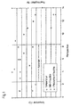
- FIG. 1 shows a purely exemplary drying and web temperature profile of SC paper in a conventional calender.
- On the abscissa of the diagram shown are several consecutively arranged in the web running measuring positions for the plotted on the left ordinate temperature or for the plotted on the right ordinate moisture content.
- the measuring positions 3 to 8 are inside the calender, the measuring positions 1 and 2 in front and the measuring positions 9 to 14 behind.
- the measured moisture directly before and the measured moisture immediately after the calender are indicated for the individual measuring positions.
- the steam humidifiers normally used can completely compensate for the loss of moisture during the calendering process. Accordingly, the paper web must be relatively heavily over-moistened by means of a jet humidifier before the calender or less dried in the dryer section. Accordingly, it can be seen from the diagram that the input moisture of the paper web in front of the calender is significantly above the moisture required for the final quality.
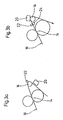
- Fig. 2 shows in a purely schematic representation of an embodiment of a calender 10 according to the invention for smoothing a material web 12, which may be in particular a paper or board web.
- the calender 10 comprises a plurality of nips 14 each formed between a pair of rollers, through which the material web 12 to be smoothed is guided. Before or behind the respective calendering tips 14 is the material web 12 led to guide rollers 18. Moreover, several steam humidifiers 18 are provided.
- a plurality in the web running direction L one behind the other, a respective distance from each other having Düsenbefeuchterüen 20 are provided to backfeed the web of material L during its passage through the calender 10 at different in web running direction L consecutive points.
- the Düsenbefeuchterüen 20 are arranged in the region of the respective web exit of the calendering tips 14, in each case directly to the respective web exit.
- an additional guide roller as a pole (earthing) of the electrostatic charge.
- the nozzle humidifier units 20 at least substantially only the amount of water removed by the respective nip 14 from the material web 12 is returned or the expected moisture loss of the subsequent nip compensated.
- Nozzle humidifier units will be used. These may in particular be designed to produce water droplets of a size which is less than about 30 microns and preferably in a range of about 1 to about 30 microns. In principle, both single-substance and dual-substance nozzle humidification units can be used. In particular, a water / air mixture is then produced with a respective two-substance nozzle humidifier unit.
- means 22 for the electrostatic charging of the material web 12 can be provided in particular in order to support the humidification effected by the respective nozzle humidifier unit 20.
- Such means 22 are merely indicated by way of example on the back moisturizing point located behind the first nip 14. In principle, however, such electrostatic charging means 22 may also be provided at other remoistening sites.
- FIG. 2 are further, not inventive installation positions shown.
- the nozzle humidifier units 20 may in particular be designed so that an amount of water in a range from about 0.1 to 5% by weight is delivered to the material web surface at the respective rewet bodies.
- the Indian FIG. 2 illustrated calender 10 is inclined relative to the vertical. In principle, however, the calender 10 can also be oriented vertically. Apart from that, a calender divided into several stacks is also conceivable.
- the input moisture of the material web 12 in front of the calender 10 can at least essentially be brought to the dry content required for the final quality.
- FIGS. 3a) and 3b ) do not show arrangements according to the invention for moistening with electrostatic charging.
- At least a portion of the moistening units 20 may be provided immediately after a respective guide roller 16.
- the respective guide roller 16 can serve, for example, as a pole for an electrostatic charge.
- At least one additional guide roller 24 may be provided as a pole (eg ground) for electrostatic charging.
- This guide roller 24 are associated with corresponding means 22 for electrostatic charging.
- the additional guide roller 24 is arranged in front of a guide roller 16. In the area of the guide roller 16, a moistening unit 20 is again provided.
- the means 22 for electrostatic charging are preferably provided in the region of a guide roller 24, which can serve, for example, again as a pole for the electrostatic charge.
Landscapes
- Paper (AREA)
Claims (29)
- Procédé de lissage d'une bande de matériau (12), en particulier d'une bande de papier ou de carton, au moyen d'au moins une calandre (10) avec des emprises (14) à travers lesquelles est guidée la bande de matériau à lisser (12), la bande de matériau (12) étant humidifiée pendant le satinage par un humidificateur à vapeur (18) et tempérée, et l'humidité est extraite hors de la bande de matériau (12) par ce satinage,
caractérisé en ce que pendant son passage à travers la calandre (10), la bande de matériau (12) est ré-humidifiée directement à la sortie de la bande hors d'une emprise de calandre (14) respective à plusieurs emplacements situés les uns derrière les autres en direction de circulation de bande (L) et présentant une distance respective les uns des autres au moyen d'une unité d'humidification respective supplémentaire (20), afin d'assurer une ré-humidification échelonnée pendant le processus de calandrage, par laquelle on compense les pertes d'humidité. - Procédé selon la revendication 1, caractérisé en ce qu'en direction de circulation de bande (L), la bande de matériau (12) est ré-humidifiée après une partie au moins des passages à travers les emprises, de préférence après chaque passage d'emprise.
- Procédé selon l'une ou l'autre des revendications 1 et 2, caractérisé en ce qu'aux emplacements de ré-humidification prévus après une emprise de calandre respective (14), on ajoute ou on remet au moins sensiblement uniquement la quantité d'eau respective évacuée de la bande de matériau (12) par l'emprise respective (14).
- Procédé selon la revendication 1, caractérisé en ce que l'on utilise une unité d'humidification à buses (20) qui génère des gouttelettes d'eau d'une taille inférieure à environ 30 µm et de préférence dans une plage d'environ 1 à environ 30 µm.
- Procédé selon l'une ou l'autre des revendications 1 et 4, caractérisé en ce que l'on utilise une unité d'humidification à buses (20) à substance unique.
- Procédé selon les revendications 1 à 4, caractérisé en ce que l'on utilise une unité d'humidification à buses (20) à deux substances, pour générer en particulier un mélange air/liquide (par exemple une solution).
- Procédé selon l'une des revendications précédentes, caractérisé en ce qu'une ré-humidification respective assurée au moyen d'une unité d'humidification à buses (20) est assistée par une charge électrostatique de la bande de matériau (12).
- Procédé selon l'une des revendications 1 à 6, caractérisé en ce qu'une ré-humidification respective assurée au moyen d'une unité d'humidification à buses (20) s'effectue sans charge électrostatique de la bande de matériau (12).
- Procédé selon l'une des revendications précédentes, caractérisé en ce qu'à un emplacement de ré-humidification respectif, on remet à la surface de la bande de matériau une quantité d'eau dans une plage d'environ 0,1 à environ 5 % en poids.
- Procédé selon l'une des revendications précédentes, caractérisé en ce que lors de la ré-humidification à assurer, l'humidification et la températion de la bande de matériau (12) sont prises en compte par les humidificateurs à vapeur prévus (18).
- Procédé selon l'une des revendications précédentes, caractérisé en ce que l'humidité d'entrée de la bande de matériau (12) en avant de la calandre (10) est amenée au moins sensiblement à la teneur en matière sèche nécessaire pour la qualité finale.
- Procédé selon l'une des revendications précédentes, caractérisé en ce qu'il est prévu au moins un humidificateur à buses (20) et/ou au moins un humidificateur à vapeur pour un profilage transversal.
- Procédé selon l'une des revendications précédentes, caractérisé en ce qu'au moins un cylindre maître supplémentaire (24) est prévu à titre de pôle (par exemple de mise à la terre) pour une charge électrostatique.
- Procédé selon l'une des revendications précédentes, caractérisé en ce qu'en avant de la calandre s'effectue une ré-humidification avec au moins un humidificateur à buses (20) et une charge électrostatique de la bande de matériau fibreux avec des buses à une substance et/ou à deux substances.
- Calandre (10) pour lisser une bande de matériau (12), en particulier une bande de papier ou de carton, présentant plusieurs emprises (14) à travers lesquelles est guidée la bande de matériau à lisser (12), et plusieurs humidificateurs à vapeur (18) pour humidifier et tempérer la bande de matériau (12) pendant le satinage, de l'humidité étant extraite de la bande de matériau (12) du fait du satinage, en particulier pour mettre en oeuvre le procédé selon l'une des revendications précédentes,
caractérisée en ce qu'il est prévu plusieurs unités d'humidification supplémentaires (20) directement à la sortie de la bande hors d'une emprise de calandre respective, situées les unes derrière les autres en direction de circulation de bande (L) et présentant une distance respective les unes des autres, afin de ré-humidifier la bande de matériau (12) pendant son passage à travers la calandre (10) à différents emplacements situés les uns derrière les autres en direction de circulation de bande (L), afin d'assurer une ré-humidification échelonnée pendant le processus de calandrage, par laquelle les pertes d'humidité sont compensées. - Calandre selon la revendication 15, caractérisée en ce qu'en direction de circulation de bande (L), en avant ou en arrière d'une partie au moins des emprises, de préférence après chaque emprise (14), il est prévu un humidificateur à buses respectif (20).
- Calandre selon l'une ou l'autre des revendications 15 et 16, caractérisée en ce qu'au moyen des humidificateurs à buses (20) prévus après une emprise de calandre respective (14), au moins sensiblement uniquement la quantité d'eau respective évacuée de la bande de matériau (12) par l'emprise respective (14) est ajoutée.
- Calandre selon la revendication 15, caractérisée en ce que l'unité d'humidification à buses (20) est réalisée pour générer des gouttelettes d'eau d'une taille inférieure à environ 30 µm et de préférence dans une plage d'environ 1 à environ 30 µm.
- Calandre selon l'une ou l'autre des revendications 15 et 18, caractérisée en ce qu'il est prévu à titre d'unité d'humidification à buses (20) une unité d'humidification à buses à substance unique.
- Calandre selon l'une des revendications 15 à 18, caractérisée en ce qu'il est prévu à titre d'unité d'humidification à buses (20) une unité d'humidification à buses à deux substances, pour générer en particulier un mélange air/liquide (par exemple une solution).
- Calandre selon l'une des revendications 15 à 20, caractérisée en ce qu'il est prévu, outre une unité d'humidification à buses respective (20), des moyens (22) pour la charge électrostatique de la bande de matériau (12), afin d'assister la ré-humidification assurée par l'unité d'humidification à buses (20) et d'accélérer la pénétration dans la surface de la bande.
- Calandre selon l'une des revendications 15 à 21, caractérisée en ce que les humidificateurs à buses (20) sont réalisés chacun de telle sorte qu'aux emplacements de ré-humidification respectifs, une quantité d'eau dans une plage d'environ 0,1 à environ 5 % en poids est remise à la surface de la bande de matériau.
- Calandre selon l'une des revendications 15 à 22, caractérisée en ce qu'elle est inclinée par rapport à la verticale.
- Calandre selon l'une des revendications 15 à 23, caractérisée en ce qu'elle est orientée au moins sensiblement verticalement.
- Calandre selon l'une des revendications 15 à 24, caractérisée en ce qu'elle est subdivisée en plusieurs empilements.
- Calandre selon l'une des revendications 15 à 23 ou 25, caractérisée en ce qu'elle est orientée sensiblement horizontalement (par exemple lisseuse "soft").
- Calandre selon l'une des revendications 15 à 26, caractérisée en ce qu'au moins un cylindre maître supplémentaire (24) est prévu à titre de pôle (par exemple de mise à la terre) pour une charge électrostatique.
- Calandre selon l'une des revendications 15 à 27, caractérisée en ce qu'il est prévu en avant de la calandre au moins un humidificateur à buses (20) servant à la ré-humidification et des moyens (22) pour la charge électrostatique.
- Calandre selon l'une des revendications 15 à 28, caractérisée en ce qu'au moins un humidificateur à buses (20) et/ou au moins un humidificateur à vapeur est réalisé pour un profilage transversal.
Applications Claiming Priority (2)
| Application Number | Priority Date | Filing Date | Title |
|---|---|---|---|
| DE10052187 | 2000-10-20 | ||
| DE10052187A DE10052187B4 (de) | 2000-10-20 | 2000-10-20 | Verfahren zum Glätten einer Materialbahn sowie Kalander zur Durchführung des Verfahrens |
Publications (4)
| Publication Number | Publication Date |
|---|---|
| EP1199404A2 EP1199404A2 (fr) | 2002-04-24 |
| EP1199404A3 EP1199404A3 (fr) | 2003-04-02 |
| EP1199404B1 EP1199404B1 (fr) | 2005-01-26 |
| EP1199404B2 true EP1199404B2 (fr) | 2011-12-14 |
Family
ID=7660534
Family Applications (1)
| Application Number | Title | Priority Date | Filing Date |
|---|---|---|---|
| EP01124969A Expired - Lifetime EP1199404B2 (fr) | 2000-10-20 | 2001-10-19 | Procédé et dispositif de calandrage d'une bande |
Country Status (2)
| Country | Link |
|---|---|
| EP (1) | EP1199404B2 (fr) |
| DE (2) | DE10052187B4 (fr) |
Families Citing this family (5)
| Publication number | Priority date | Publication date | Assignee | Title |
|---|---|---|---|---|
| DE10061274A1 (de) * | 2000-12-08 | 2002-06-13 | Voith Paper Patent Gmbh | Maschine zur Herstellung einer Faserstoffbahn |
| DE10233795A1 (de) | 2002-07-25 | 2004-02-12 | Voith Paper Patent Gmbh | Trockenpartie |
| FI119195B (fi) * | 2003-07-02 | 2008-08-29 | Metso Paper Inc | Menetelmä ja järjestely kuiturainan kostuttamiseksi |
| DE10358186B4 (de) * | 2003-12-12 | 2006-09-07 | Voith Paper Patent Gmbh | Verfahren zum Behandeln einer Papierbahn |
| FI122758B (fi) | 2008-02-15 | 2012-06-29 | Metso Paper Inc | Monitelakalanteri ja menetelmä monitelakalanterissa |
Citations (4)
| Publication number | Priority date | Publication date | Assignee | Title |
|---|---|---|---|---|
| US2214641A (en) † | 1937-07-17 | 1940-09-10 | Combined Locks Paper Company | Process of producing rotogravure paper and the like |
| DE3542342A1 (de) † | 1984-11-30 | 1986-06-05 | Osakeyhtiö Wärtsilä Ab, Helsinki | Verfahren und anordnung zum kalandern von papier- oder pappebahnen |
| EP0618328B1 (fr) † | 1993-03-20 | 1996-12-11 | V.I.B. Apparatebau GmbH | Distributeur de vapeur et procédé pour contrÔler le lissé et/ou la brillance d'une bande |
| EP0957202B1 (fr) † | 1998-05-08 | 2004-03-31 | V.I.B. Systems GmbH | Procédé et dispositif pour la fabrication de papier SC-A online |
Family Cites Families (14)
| Publication number | Priority date | Publication date | Assignee | Title |
|---|---|---|---|---|
| US3625743A (en) * | 1967-12-12 | 1971-12-07 | Tamotsu Watanabe | Method for impregnating running paper with moisture |
| FI71966C (fi) * | 1983-11-22 | 1987-03-09 | Myllykoski Oy | Foerfarande och anordning foer fuktning av en pappersbana. |
| FI72552C (fi) * | 1984-02-08 | 1987-06-08 | Waertsilae Oy Ab | Foerfarande och anordning foer behandling av bana. |
| DE3741680A1 (de) * | 1987-12-09 | 1989-06-22 | Pagendarm Gmbh | Verfahren und vorrichtung zum glaetten der oberflaeche einer papierbahn |
| US5065673A (en) * | 1989-09-19 | 1991-11-19 | Measurex Corporation | Cross-directional moisture control system and method |
| DE4309076C2 (de) * | 1993-03-20 | 1995-03-09 | Vib Apparatebau Gmbh | Dampfsprührohr |
| JPH07258992A (ja) * | 1994-03-17 | 1995-10-09 | Nippon Paper Ind Co Ltd | 製紙用カレンダ装置 |
| DE19508353A1 (de) * | 1995-03-09 | 1996-09-12 | Voith Sulzer Finishing Gmbh | Kalander für die zweiseitige Behandlung einer Papierbahn |
| US5607553A (en) * | 1995-08-29 | 1997-03-04 | Westvaco Corporation | Method and apparatus for finishing paper |
| DE19757472C2 (de) * | 1997-12-23 | 2000-09-07 | Voith Sulzer Papiermasch Gmbh | Kalander für eine Bahn, insbesondere Papierbahn |
| DE19826899B4 (de) * | 1998-05-08 | 2005-05-19 | V.I.B. Systems Gmbh | Verfahren und Vorrichtung zur Online-Kalandrierung von SC-A-Papier |
| DE19835989C5 (de) * | 1998-08-08 | 2010-04-01 | V.I.B. Systems Gmbh | Verfahren und Vorrichtung zur Online-Kalandrierung von Papier |
| DE19904451B4 (de) * | 1999-02-04 | 2005-06-30 | Voith Paper Patent Gmbh | Kalander für bahnförmige Materialien wie Papier |
| US6113743A (en) * | 1999-06-16 | 2000-09-05 | Vice; Gerald | End dam for waterbox of paper making machine |
-
2000
- 2000-10-20 DE DE10052187A patent/DE10052187B4/de not_active Expired - Fee Related
-
2001
- 2001-10-19 DE DE50105181T patent/DE50105181D1/de not_active Expired - Lifetime
- 2001-10-19 EP EP01124969A patent/EP1199404B2/fr not_active Expired - Lifetime
Patent Citations (4)
| Publication number | Priority date | Publication date | Assignee | Title |
|---|---|---|---|---|
| US2214641A (en) † | 1937-07-17 | 1940-09-10 | Combined Locks Paper Company | Process of producing rotogravure paper and the like |
| DE3542342A1 (de) † | 1984-11-30 | 1986-06-05 | Osakeyhtiö Wärtsilä Ab, Helsinki | Verfahren und anordnung zum kalandern von papier- oder pappebahnen |
| EP0618328B1 (fr) † | 1993-03-20 | 1996-12-11 | V.I.B. Apparatebau GmbH | Distributeur de vapeur et procédé pour contrÔler le lissé et/ou la brillance d'une bande |
| EP0957202B1 (fr) † | 1998-05-08 | 2004-03-31 | V.I.B. Systems GmbH | Procédé et dispositif pour la fabrication de papier SC-A online |
Non-Patent Citations (1)
| Title |
|---|
| ANONYM: "Die neuen Superkalander Konzepte", SULZER PAPERTEC, PAPER FINISHING, 1994, pages 16 - 17 † |
Also Published As
| Publication number | Publication date |
|---|---|
| DE10052187B4 (de) | 2013-12-24 |
| DE10052187A1 (de) | 2002-05-02 |
| DE50105181D1 (de) | 2005-03-03 |
| EP1199404A2 (fr) | 2002-04-24 |
| EP1199404B1 (fr) | 2005-01-26 |
| EP1199404A3 (fr) | 2003-04-02 |
Similar Documents
| Publication | Publication Date | Title |
|---|---|---|
| DE69620020T2 (de) | Verfahren und vorrichtung in einer papiermaschine | |
| DE69915647T2 (de) | Verfahren zur herstellung von kalandriertem papier | |
| DE19826899B4 (de) | Verfahren und Vorrichtung zur Online-Kalandrierung von SC-A-Papier | |
| EP1020559B1 (fr) | Dispositif pour secher et lisser des bandes fibreuses | |
| DE69834675T2 (de) | Vorrichtung zum Aufbringen von Luft auf eine Bahn | |
| DE29815847U1 (de) | Vorrichtung zur Online-Herstellung von Papier | |
| EP1199404B2 (fr) | Procédé et dispositif de calandrage d'une bande | |
| WO2005052252A1 (fr) | Machine a papier | |
| DE10102199A1 (de) | Verfahren zur Konditionierung eines umlaufenden Filzbandes | |
| DE69617522T2 (de) | Trockenpartie mit einer Kombination von Einsieb- und Doppelsiebtrockengruppen | |
| EP0957202B1 (fr) | Procédé et dispositif pour la fabrication de papier SC-A online | |
| EP2119827B1 (fr) | Procédé de calandrage d'une bande fibreuse et calandre | |
| EP1586697B1 (fr) | Machine à papier | |
| EP1335066B1 (fr) | Procédé et appareil pour la fabrication et le traitement d'une bande de papier | |
| EP1540078B1 (fr) | Dispositif et procede de production et/ou traitement d'une bande de matiere fibreuse | |
| DE102006011853A1 (de) | Verfahren und Vorrichtung zum Befeuchten einer Faserstoffbahn | |
| DE10358185B4 (de) | Verfahren zum Behandeln einer Papierbahn | |
| EP1541757B1 (fr) | Procédé de satinage d'une bande de papier ou carton couchée et calandre | |
| EP0169988B2 (fr) | Procédé pour l'amélioration du papier et dispositif pour l'application du procédé | |
| DE10358189B4 (de) | Verfahren und Vorrichtung zum Behandeln einer Bahn aus Papier oder Karton | |
| DE19821820A1 (de) | Vorrichtung zur Oberflächenbehandlung einer laufenden Materialbahn, insbesondere aus Karton | |
| DE10056138A1 (de) | Pressenpartie | |
| EP1746203B1 (fr) | Section de séchage | |
| DE102005035558A1 (de) | Papiermaschine mit einem Pressspalt und Verfahren zum Einstellen des Feuchtequerprofils einer Papierbahn | |
| DE10024295A1 (de) | Zylinderanordnung einer Maschine zur Herstellung einer Materialbahn |
Legal Events
| Date | Code | Title | Description |
|---|---|---|---|
| PUAI | Public reference made under article 153(3) epc to a published international application that has entered the european phase |
Free format text: ORIGINAL CODE: 0009012 |
|
| AK | Designated contracting states |
Kind code of ref document: A2 Designated state(s): AT BE CH CY DE DK ES FI FR GB GR IE IT LI LU MC NL PT SE TR |
|
| AX | Request for extension of the european patent |
Free format text: AL;LT;LV;MK;RO;SI |
|
| PUAL | Search report despatched |
Free format text: ORIGINAL CODE: 0009013 |
|
| AK | Designated contracting states |
Kind code of ref document: A3 Designated state(s): AT BE CH CY DE DK ES FI FR GB GR IE IT LI LU MC NL PT SE TR |
|
| AX | Request for extension of the european patent |
Extension state: AL LT LV MK RO SI |
|
| 17P | Request for examination filed |
Effective date: 20030429 |
|
| 17Q | First examination report despatched |
Effective date: 20030805 |
|
| AKX | Designation fees paid |
Designated state(s): DE FI SE |
|
| GRAP | Despatch of communication of intention to grant a patent |
Free format text: ORIGINAL CODE: EPIDOSNIGR1 |
|
| GRAS | Grant fee paid |
Free format text: ORIGINAL CODE: EPIDOSNIGR3 |
|
| GRAA | (expected) grant |
Free format text: ORIGINAL CODE: 0009210 |
|
| AK | Designated contracting states |
Kind code of ref document: B1 Designated state(s): DE FI SE |
|
| REG | Reference to a national code |
Ref country code: IE Ref legal event code: FG4D Free format text: GERMAN |
|
| REF | Corresponds to: |
Ref document number: 50105181 Country of ref document: DE Date of ref document: 20050303 Kind code of ref document: P |
|
| REG | Reference to a national code |
Ref country code: SE Ref legal event code: TRGR |
|
| PLBI | Opposition filed |
Free format text: ORIGINAL CODE: 0009260 |
|
| PLBI | Opposition filed |
Free format text: ORIGINAL CODE: 0009260 |
|
| PLAX | Notice of opposition and request to file observation + time limit sent |
Free format text: ORIGINAL CODE: EPIDOSNOBS2 |
|
| 26 | Opposition filed |
Opponent name: EDUARD KUESTERSMASCHINENFABRIK GMBH & CO. KG Effective date: 20051025 |
|
| 26 | Opposition filed |
Opponent name: V.I.B SYSTEMS GMBHPATENTANWAELTE Effective date: 20051026 Opponent name: EDUARD KUESTERSMASCHINENFABRIK GMBH & CO. KG Effective date: 20051025 |
|
| PLBB | Reply of patent proprietor to notice(s) of opposition received |
Free format text: ORIGINAL CODE: EPIDOSNOBS3 |
|
| RAP2 | Party data changed (patent owner data changed or rights of a patent transferred) |
Owner name: VOITH PATENT GMBH |
|
| PLAB | Opposition data, opponent's data or that of the opponent's representative modified |
Free format text: ORIGINAL CODE: 0009299OPPO |
|
| R26 | Opposition filed (corrected) |
Opponent name: ANDRITZ KUESTERS GMBH & CO. KG Effective date: 20051025 Opponent name: V.I.B SYSTEMS GMBH Effective date: 20051026 |
|
| PLAB | Opposition data, opponent's data or that of the opponent's representative modified |
Free format text: ORIGINAL CODE: 0009299OPPO |
|
| R26 | Opposition filed (corrected) |
Opponent name: V.I.B SYSTEMS GMBH Effective date: 20051026 Opponent name: ANDRITZ KUESTERS GMBH Effective date: 20051025 |
|
| RIC2 | Information provided on ipc code assigned after grant |
Ipc: D07B 1/16 20060101AFI20110128BHEP |
|
| PUAH | Patent maintained in amended form |
Free format text: ORIGINAL CODE: 0009272 |
|
| STAA | Information on the status of an ep patent application or granted ep patent |
Free format text: STATUS: PATENT MAINTAINED AS AMENDED |
|
| 27A | Patent maintained in amended form |
Effective date: 20111214 |
|
| AK | Designated contracting states |
Kind code of ref document: B2 Designated state(s): DE FI SE |
|
| REG | Reference to a national code |
Ref country code: DE Ref legal event code: R102 Ref document number: 50105181 Country of ref document: DE |
|
| PGFP | Annual fee paid to national office [announced via postgrant information from national office to epo] |
Ref country code: SE Payment date: 20111021 Year of fee payment: 11 |
|
| REG | Reference to a national code |
Ref country code: DE Ref legal event code: R102 Ref document number: 50105181 Country of ref document: DE Effective date: 20111214 |
|
| REG | Reference to a national code |
Ref country code: SE Ref legal event code: RPEO |
|
| PG25 | Lapsed in a contracting state [announced via postgrant information from national office to epo] |
Ref country code: SE Free format text: LAPSE BECAUSE OF NON-PAYMENT OF DUE FEES Effective date: 20121020 |
|
| PGFP | Annual fee paid to national office [announced via postgrant information from national office to epo] |
Ref country code: DE Payment date: 20131021 Year of fee payment: 13 |
|
| PGFP | Annual fee paid to national office [announced via postgrant information from national office to epo] |
Ref country code: FI Payment date: 20131011 Year of fee payment: 13 |
|
| REG | Reference to a national code |
Ref country code: DE Ref legal event code: R119 Ref document number: 50105181 Country of ref document: DE |
|
| PG25 | Lapsed in a contracting state [announced via postgrant information from national office to epo] |
Ref country code: FI Free format text: LAPSE BECAUSE OF NON-PAYMENT OF DUE FEES Effective date: 20141019 Ref country code: DE Free format text: LAPSE BECAUSE OF NON-PAYMENT OF DUE FEES Effective date: 20150501 |