EP1199404B2 - Method and device for calendering a web - Google Patents
Method and device for calendering a web Download PDFInfo
- Publication number
- EP1199404B2 EP1199404B2 EP01124969A EP01124969A EP1199404B2 EP 1199404 B2 EP1199404 B2 EP 1199404B2 EP 01124969 A EP01124969 A EP 01124969A EP 01124969 A EP01124969 A EP 01124969A EP 1199404 B2 EP1199404 B2 EP 1199404B2
- Authority
- EP
- European Patent Office
- Prior art keywords
- accordance
- calender
- material web
- web
- humidifier unit
- Prior art date
- Legal status (The legal status is an assumption and is not a legal conclusion. Google has not performed a legal analysis and makes no representation as to the accuracy of the status listed.)
- Expired - Lifetime
Links
Images

Classifications
-
- D—TEXTILES; PAPER
- D21—PAPER-MAKING; PRODUCTION OF CELLULOSE
- D21G—CALENDERS; ACCESSORIES FOR PAPER-MAKING MACHINES
- D21G7/00—Damping devices
-
- D—TEXTILES; PAPER
- D21—PAPER-MAKING; PRODUCTION OF CELLULOSE
- D21G—CALENDERS; ACCESSORIES FOR PAPER-MAKING MACHINES
- D21G1/00—Calenders; Smoothing apparatus
- D21G1/0073—Accessories for calenders
- D21G1/0093—Web conditioning devices
Definitions
- the invention relates to a method for smoothing a material web according to the preamble of claim 1. It further relates to a calender specified in the preamble of claim 15.
- Art and calender of this type are, for example, in the publications EP-A-0 957 202 and US-A-5 065 673 described.
- the paper web Due to the high pressures acting on the calendering process and the simultaneous use of steam humidifiers and heated tempering rollers, the paper web is deprived of moisture during the calendering process or the paper is dried out. This drying can lead to an over-drying of the sheet structure with an insufficient residual moisture in the paper, whereby the calendering is adversely affected while the strength of the paper is greatly reduced.
- the paper web In order to compensate for the moisture losses of the paper web during the calendering, the paper web must currently be moistened so far or less dried that it has a well-defined final moisture after calendering and before the pop roller or drum reel roller. This has previously been achieved by a single moistening by Düsenbefeuchtern before the calender and during the calendering process by the use of steam humidifiers. However, this steam humidifier can not fully compensate for the loss of moisture during the calendering, so that the paper web must be partially over-moistened by a Düsenbefeuchters depending on the calendering, the pressure and the distance between the dryer section and Poperoller.
- the aim of the invention is to provide an improved method and an improved calender of the type mentioned, in which the aforementioned disadvantages are eliminated.
- the moistening of the material web can be reduced to the outermost web layers, whereby the compaction of the web is kept at the lowest possible level and still obtain a maximum calendering effect on the material web surface, so a so-called Totkalandr Schl is avoided.
- At least essentially only the water quantity removed from the material web by the respective nip is returned to the re-wetting points provided after a respective calender nip.
- a nozzle humidifier unit is used at a respective rewet body, which produces water droplets of a size which is smaller than about 30 microns and preferably in a range of about 1 to 30 microns.
- a single-substance nozzle humidifier unit or, for example, also a two-substance nozzle humidifier unit can be used, in order in particular to produce a water / air mixture.
- a respective remoistening effected by means of a nozzle humidifier unit can be assisted by an electrostatic charge of the material web.
- such rewetting by means of a nozzle humidifier unit can also be carried out without electrostatic charging of the material web.
- the use of the nozzle humidifier units serves to return the moisture vaporized by the hot calendering process to the material web surface.
- the contact time which is dependent on the distance between a respective moistening point and the next nip and the material web speed, possibly the average Wasserropfstil and the efficiency of water transfer to the material web is crucial. Possibly. can be further improved at a sufficiently high dry content by the use of the electrostatic charge of the web, the transfer of liquid droplets.
- the most uniform moistening of the material web on the surface comparable to a closed liquid film, is to be achieved.
- a quantity of water in a range from about 0.1 to about 5% by weight is returned to the material web surface at a respective rewetting point.
- the input moisture of the material web before the calender is at least substantially brought to the dry content required for the final quality.
- a transverse profiling of advantage It is therefore expedient if at least one corresponding nozzle humidifier unit and / or at least one corresponding steam humidifier is provided for such a transverse profiling. It can be provided, for example, a regulation of the smoothness result and / or care for the most uniform possible moisture over the web width. Since a different evaporation (drying) is to be expected due to different line forces, a profiling, for example, would also be conceivable in the calender. In the foreground, however, is not the general regulation of the parameters, but much more important is the possibility of profiling.
- At least one additional guide roll as a pole (e.g., ground) for electrostatic charging.
- the electrostatic charge may be provided, for example, in front of a respective guide roller.
- a moistening unit can again be provided.
- the moistening may be provided with additives which favorably influence the calendering process, e.g. the paper properties such as Improve shine and smoothness.
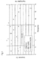
- FIG. 1 shows a purely exemplary drying and web temperature profile of SC paper in a conventional calender.
- On the abscissa of the diagram shown are several consecutively arranged in the web running measuring positions for the plotted on the left ordinate temperature or for the plotted on the right ordinate moisture content.
- the measuring positions 3 to 8 are inside the calender, the measuring positions 1 and 2 in front and the measuring positions 9 to 14 behind.
- the measured moisture directly before and the measured moisture immediately after the calender are indicated for the individual measuring positions.
- the steam humidifiers normally used can completely compensate for the loss of moisture during the calendering process. Accordingly, the paper web must be relatively heavily over-moistened by means of a jet humidifier before the calender or less dried in the dryer section. Accordingly, it can be seen from the diagram that the input moisture of the paper web in front of the calender is significantly above the moisture required for the final quality.
- Fig. 2 shows in a purely schematic representation of an embodiment of a calender 10 according to the invention for smoothing a material web 12, which may be in particular a paper or board web.
- the calender 10 comprises a plurality of nips 14 each formed between a pair of rollers, through which the material web 12 to be smoothed is guided. Before or behind the respective calendering tips 14 is the material web 12 led to guide rollers 18. Moreover, several steam humidifiers 18 are provided.
- a plurality in the web running direction L one behind the other, a respective distance from each other having Düsenbefeuchterüen 20 are provided to backfeed the web of material L during its passage through the calender 10 at different in web running direction L consecutive points.
- the Düsenbefeuchterüen 20 are arranged in the region of the respective web exit of the calendering tips 14, in each case directly to the respective web exit.
- an additional guide roller as a pole (earthing) of the electrostatic charge.
- the nozzle humidifier units 20 at least substantially only the amount of water removed by the respective nip 14 from the material web 12 is returned or the expected moisture loss of the subsequent nip compensated.
- Nozzle humidifier units will be used. These may in particular be designed to produce water droplets of a size which is less than about 30 microns and preferably in a range of about 1 to about 30 microns. In principle, both single-substance and dual-substance nozzle humidification units can be used. In particular, a water / air mixture is then produced with a respective two-substance nozzle humidifier unit.
- means 22 for the electrostatic charging of the material web 12 can be provided in particular in order to support the humidification effected by the respective nozzle humidifier unit 20.
- Such means 22 are merely indicated by way of example on the back moisturizing point located behind the first nip 14. In principle, however, such electrostatic charging means 22 may also be provided at other remoistening sites.
- FIG. 2 are further, not inventive installation positions shown.
- the nozzle humidifier units 20 may in particular be designed so that an amount of water in a range from about 0.1 to 5% by weight is delivered to the material web surface at the respective rewet bodies.
- the Indian FIG. 2 illustrated calender 10 is inclined relative to the vertical. In principle, however, the calender 10 can also be oriented vertically. Apart from that, a calender divided into several stacks is also conceivable.
- the input moisture of the material web 12 in front of the calender 10 can at least essentially be brought to the dry content required for the final quality.
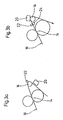
- FIGS. 3a) and 3b ) do not show arrangements according to the invention for moistening with electrostatic charging.
- At least a portion of the moistening units 20 may be provided immediately after a respective guide roller 16.
- the respective guide roller 16 can serve, for example, as a pole for an electrostatic charge.
- At least one additional guide roller 24 may be provided as a pole (eg ground) for electrostatic charging.
- This guide roller 24 are associated with corresponding means 22 for electrostatic charging.
- the additional guide roller 24 is arranged in front of a guide roller 16. In the area of the guide roller 16, a moistening unit 20 is again provided.
- the means 22 for electrostatic charging are preferably provided in the region of a guide roller 24, which can serve, for example, again as a pole for the electrostatic charge.
Description
Die Erfindung betrifft ein Verfahren zum Glätten einer Materialbahn gemäß dem Oberbegriff des Anspruchs 1. Sie betrifft ferner einen Kalander der im Oberbegriff des Anspruchs 15 angegebenen Art. Verfahren und Kalander dieser Art sind beispielsweise in den Druckschriften
Durch die bei der Satinage wirkenden hohen Drücke und den gleichzeitigen Einsatz von Dampfbefeuchtern und beheizten Temperierwalzen wird der Papierbahn während der Satinage Feuchtigkeit entzogen bzw. das Papier ausgetrocknet. Diese Trocknung kann bei einer nicht ausreichenden Restfeuchtigkeit im Papier zu einer Übertrocknung des Blattgefüges führen, wodurch die Satinage negativ beeinflusst und gleichzeitig die Festigkeit des Papiers stark reduziert wird.Due to the high pressures acting on the calendering process and the simultaneous use of steam humidifiers and heated tempering rollers, the paper web is deprived of moisture during the calendering process or the paper is dried out. This drying can lead to an over-drying of the sheet structure with an insufficient residual moisture in the paper, whereby the calendering is adversely affected while the strength of the paper is greatly reduced.
Um die Feuchteverluste der Papierbahn während der Satinage zu kompensieren, muss die Papierbahn derzeit so weit angefeuchtet bzw. weniger getrocknet werden, dass sie nach dem Kalandrieren und vor dem Poperoller oder Tragtrommelroller eine genau definierte Endfeuchte besitzt. Dies wird bisher durch eine einmalige Auffeuchtung mittels Düsenbefeuchtern vor dem Kalander und während des Kalandrierprozesses durch den Einsatz von Dampfbefeuchtern erreicht. Dieses Dampfbefeuchter können jedoch den Feuchteverlust während der Satinage nicht vollständig kompensieren, so dass die Papierbahn mittels eines Düsenbefeuchters in Abhängigkeit von der Satinagetemperatur, des Drucks und der Wegstrecke zwischen Trockenpartie und Poperoller teilweise stark überfeuchtet werden muss.In order to compensate for the moisture losses of the paper web during the calendering, the paper web must currently be moistened so far or less dried that it has a well-defined final moisture after calendering and before the pop roller or drum reel roller. This has previously been achieved by a single moistening by Düsenbefeuchtern before the calender and during the calendering process by the use of steam humidifiers. However, this steam humidifier can not fully compensate for the loss of moisture during the calendering, so that the paper web must be partially over-moistened by a Düsenbefeuchters depending on the calendering, the pressure and the distance between the dryer section and Poperoller.
Die aus der
Auch der aus der
Ziel der Erfindung ist es, ein verbessertes Verfahren sowie einen verbesserten Kalander der eingangs genannten Art zu schaffen, bei denen die zuvor genannten Nachteile beseitigt sind.The aim of the invention is to provide an improved method and an improved calender of the type mentioned, in which the aforementioned disadvantages are eliminated.
Hinsichtlich des Verfahrens wird diese Aufgabe erfindungsgemäß gelöst durch die kennzeichnenden Merkmale des Anspruchs 1. Es muss also nicht zwingend zwischen jedem Nippaar eine zusätzliche Befeuchtungseinheit vorgesehen sein.With regard to the method, this object is achieved according to the invention by the characterizing features of
Aufgrund dieser Ausgestaltung ergibt sich eine stufenweise Rückbefeuchtung der Materialbahn während des Kalandrierprozesses, mit der nun der Feuchtigkeitsverlust ausgeglichen werden kann. Damit ist eine niedrigere Eingangsfeuchte vor dem Kalander möglich, wodurch die Varianz der Feuchte im Querprofil reduziert wird. Idealerweise kann durch die verwendeten Befeuchtungseinheiten die durch den jeweiligen Nip ausgetriebene Feuchte auf die Materialbahn zurückgegeben werden, so dass im darauf 1 folgenden Nip wieder ähnliche Feuchtigkeitsbedingungen in der Materialbahn vorherrschen. Im Idealfall kann also die Eingangsfeuchte der Materialbahn vor dem Kalander auf den für die Endqualität erforderlichen Trockengehalt gesteigert werden. Überdies kann die Befeuchtung der Materialbahn auf die äußersten Materialbahnschichten reduziert werden, wodurch die Verdichtung der Materialbahn auf einem möglichst niedrigen Niveau gehalten und trotzdem eine maximale Satinagewirkung an der Materialbahnoberfläche erhalten wird, ein so genanntes Totkalandrieren wird also vermieden.Due to this configuration, a gradual remoistening of the material web results during the calendering process, with which now the moisture loss can be compensated. This allows a lower input moisture level in front of the calender, which reduces the variance of the moisture in the cross section. Ideally, by the moistening units used, the moisture expelled by the respective nip can be returned to the material web, so that in the following nip similar moisture conditions in the following nip again Material web prevail. Ideally, therefore, the input moisture of the web before the calender can be increased to the dry content required for the final quality. Moreover, the moistening of the material web can be reduced to the outermost web layers, whereby the compaction of the web is kept at the lowest possible level and still obtain a maximum calendering effect on the material web surface, so a so-called Totkalandrieren is avoided.
Bei einer bevorzugten Ausgestaltung des erfindungsgemäßen Verfahrens wird an den nach einem jeweiligen Kalandernip vorgesehenen Rückbefeuchtungsstellen zumindest im Wesentlichen jeweils nur die durch den jeweiligen Nip aus der Materialbahn entfernte Wassermenge zurückgegeben.In a preferred embodiment of the method according to the invention, at least essentially only the water quantity removed from the material web by the respective nip is returned to the re-wetting points provided after a respective calender nip.
Gemäß einer zweckmäßigen praktischen Ausgestaltung des erfindungsgemäßen Verfahrens wird an einer jeweiligen Rückbefeuchtungsstelle eine Düsenbefeuchtereinheit verwendet, die Wassertröpfchen von einer Größe erzeugt, die kleiner als etwa 30 µm ist und vorzugsweise in einem Bereich von etwa 1 bis 30 µm liegt.According to an expedient practical embodiment of the method according to the invention, a nozzle humidifier unit is used at a respective rewet body, which produces water droplets of a size which is smaller than about 30 microns and preferably in a range of about 1 to 30 microns.
Dabei kann beispielsweise jeweils eine Einstoff-Düsenbefeuchtereinheit oder beispielsweise auch eine Zweistoff-Düsenbefeuchtereinheit verwendet werden, um insbesondere ein Wasser/ Luft-Gemisch zu erzeugen.In this case, for example, in each case a single-substance nozzle humidifier unit or, for example, also a two-substance nozzle humidifier unit can be used, in order in particular to produce a water / air mixture.
Eine jeweilige mittels einer Düsenbefeuchtereinheit bewirkte Rückbefeuchtung kann durch eine elektrostatische Aufladung der Materialbahn unterstützt werden. Grundsätzlich kann eine solche Rückbefeuchtung mittels einer Düsenbefeuchtereinheit jedoch auch ohne elektrostatische Aufladung der Materialbahn erfolgen.A respective remoistening effected by means of a nozzle humidifier unit can be assisted by an electrostatic charge of the material web. In principle, however, such rewetting by means of a nozzle humidifier unit can also be carried out without electrostatic charging of the material web.
Generell dient der Einsatz der Düsenbefeuchtereinheiten dazu, die durch den heißen Kalandrierprozess verdampfte Feuchtigkeit an die Materialbahnoberfläche zurückzuführen. Dabei kommt der Einwirkzeit, die vom Abstand zwischen einer jeweiligen Befeuchtungsstelle und dem nächsten Nip sowie der Materialbahngeschwindigkeit abhängig ist, ggf. der durchschnittlichen Wassertropfgröße und dem Wirkungsgrad der Wasserübertragung auf die Materialbahn entscheidende Bedeutung zu. Ggf. kann bei ausreichend hohem Trockengehalt durch den Einsatz der elektrostatischen Aufladung der Materialbahn die Übertragung der Flüssigkeitströpfchen weiter verbessert werden. Dadurch soll insbesondere eine möglichst gleichmäßige Befeuchtung der Materialbahn an der Oberfläche, vergleichbar einem geschlossenen Flüssigkeitsfilm, erreicht werden.In general, the use of the nozzle humidifier units serves to return the moisture vaporized by the hot calendering process to the material web surface. In this case, the contact time, which is dependent on the distance between a respective moistening point and the next nip and the material web speed, possibly the average Wasserropfgröße and the efficiency of water transfer to the material web is crucial. Possibly. can be further improved at a sufficiently high dry content by the use of the electrostatic charge of the web, the transfer of liquid droplets. As a result, in particular the most uniform moistening of the material web on the surface, comparable to a closed liquid film, is to be achieved.
Gemäß einer zweckmäßigen Ausgestaltung des erfindungsgemäßen Verfahrens wird an einer jeweiligen Rückbefeuchtungsstelle eine Wassermenge in einem Bereich von etwa 0,1 bis etwa 5 Gew.-% an die Materialbahnoberfläche zurückgegeben.According to an expedient embodiment of the method according to the invention, a quantity of water in a range from about 0.1 to about 5% by weight is returned to the material web surface at a respective rewetting point.
Bei der zu bewirkenden Rückbefeuchtung müssen zur Erzielung eines optimalen Ergebnisses die zusätzliche Befeuchtung und Temperierung der Materialbahn durch eventuell vorgesehene Dampfbefeuchter berücksichtigt werden.When rewetting is to be effected, the additional moistening and tempering of the material web by possibly provided steam humidifiers must be taken into account in order to achieve an optimum result.
Es ist wenigstens eine Rückbefeuchtungsstelle im Bereich des Bahnaustritts aus dem jeweiligen Kalandernip vorgesehen. Dabei befindet sich diese Rückbefeuchtungsstelle unmittelbar an dem Bahnaustritt. In diesem Fall ergibt sich u.a. der Vorteil, dass die Oberflächenbefeuchtung durch das im Bereich des Bahnaustritts auftretende Vakuum unterstützt wird.There is at least one Rückbefeuchtungsstelle provided in the region of the web exit from the respective Kalandernip. This Rückbefeuchtungsstelle is directly at the web exit. In this case, there is the advantage, inter alia, that the surface moistening is assisted by the vacuum occurring in the region of the web exit.
Es bieten sich beispielsweise jedoch auch die Positionen der Leitwalzen vor bzw. nach den Kalandernips an, die nicht Gegenstand der Erfindung sind.However, for example, there are also the positions of the guide rollers before and after the calendering tips, which are not the subject of the invention.
Gemäß einer vorteilhaften Ausgestaltung des erfindungsgemäßen Verfahrens wird die Eingangsfeuchte der Materialbahn vor dem Kalander zumindest im Wesentlichen auf den für die Endqualität erforderlichen Trockengehalt gebracht.According to an advantageous embodiment of the method according to the invention, the input moisture of the material web before the calender is at least substantially brought to the dry content required for the final quality.
In vielen Fällen ist auch eine Querprofilierung von Vorteil. Es ist daher zweckmäßig, wenn wenigstens eine entsprechende Düsenbefeuchtereinheit und/oder wenigstens ein entsprechender Dampfbefeuchter für eine solche Querprofilierung vorgesehen ist. Es kann beispielsweise eine Regelung des Glätteergebnisses vorgesehen sein und/oder für eine möglichst gleichmäßige Feuchte über die Bahnbreite gesorgt werden. Da durch unterschiedliche Linienkräfte auch eine unterschiedliche Verdampfung (Trocknung) zu erwarten ist, wäre beispielsweise eine Profilierung grundsätzlich auch im Kalander denkbar. Im Vordergrund steht jedoch nicht die allgemeine Regelung der Parameter, wesentlich ist vielmehr die Möglichkeit der Profilierung.In many cases, a transverse profiling of advantage. It is therefore expedient if at least one corresponding nozzle humidifier unit and / or at least one corresponding steam humidifier is provided for such a transverse profiling. It can be provided, for example, a regulation of the smoothness result and / or care for the most uniform possible moisture over the web width. Since a different evaporation (drying) is to be expected due to different line forces, a profiling, for example, would also be conceivable in the calender. In the foreground, however, is not the general regulation of the parameters, but much more important is the possibility of profiling.
Grundsätzlich ist es auch möglich, zumindest eine zusätzliche Leitwalze als Pol (z.B. Erdung) für eine elektrostatische Aufladung zu verwenden.In principle, it is also possible to use at least one additional guide roll as a pole (e.g., ground) for electrostatic charging.
Dabei kann die elektrostatische Aufladung beispielsweise vor einer jeweiligen Leitwalze vorgesehen sein. Im Bereich der jeweiligen Leitwalze kann beispielsweise wieder eine Befeuchtungseinheit vorgesehen sein.In this case, the electrostatic charge may be provided, for example, in front of a respective guide roller. In the region of the respective guide roller, for example, a moistening unit can again be provided.
Gemäß einer weiteren zweckmäßigen Ausgestaltung des erfindungsgemäßen Verfahrens erfolgt vor dem Kalander eine Rückbefeuchtung mit wenigstens einem Düsenfeuchter und eine elektrostatische Aufladung der Faserstoffbahn mit Einstoff- und/oder Zweistoffdüsen.According to a further expedient embodiment of the method according to the invention is carried out in front of the calender remoistening with at least a nozzle humidifier and an electrostatic charge of the fibrous web with single-fluid and / or two-fluid nozzles.
Die Befeuchtung kann beispielsweise mit Additiven versehen sein, die den Satinageprozess günstig beeinflussen und z.B. die Papiereigenschaften wie z.B. Glanz und Glätte verbessern.For example, the moistening may be provided with additives which favorably influence the calendering process, e.g. the paper properties such as Improve shine and smoothness.
In den Unteransprüchen sind weitere vorteilhafte Ausführungsformen des erfindungsgemäßen Verfahrens angegeben.In the dependent claims further advantageous embodiments of the method according to the invention are given.
Bezüglich des Kalanders wird die eingangs genannte Aufgabe erfindungsgemäß gelöst durch die kennzeichnenden Merkmale des Anspruchs 15.With regard to the calender, the object mentioned in the introduction is achieved according to the invention by the characterizing features of claim 15.
Vorteilhafte Ausführungsformen des erfindungsgemäßen Kalanders sind in den Unteransprüchen angegeben.Advantageous embodiments of the calender according to the invention are specified in the subclaims.
Die Erfindung wird im folgenden anhand eines Ausführungsbeispiels unter Bezugnahme auf die Zeichnung näher erläutert. In dieser zeigen:
- Fig. 1
- einen rein beispielhaften Trocknungs- und Bahntem- peraturverlauf von SC-Papier in einem herkömmlichen Kalander,
- Fig. 2
- eine rein schematische Darstellung eines Ausfüh- rungsbeispiels eines erfindungsgemäßen Kalanders, und
- Filg. 3a, b)
- nicht beanspruchte Anordnungen einer Befeuchtung mit elektrostatischer Aufladung.
- Fig. 1
- a purely exemplary drying and Bahntem- peraturverlauf course of SC paper in a conventional calender,
- Fig. 2
- a purely schematic representation of an embodiment of a calender according to the invention, and
- Filg. 3a, b)
- Unclaimed arrangements of electrostatic charging humidification.
Wie dem Diagramm entnommen werden kann, können die normalerweise verwendeten Dampfbefeuchter den Feuchteverlust während der Satinage nach vollständig kompensieren. Entsprechend muss die Papierbahn mittels eines Düsenbefeuchters vor dem Kalander relativ stark überfeuchtet oder in der Trockenpartie weniger getrocknet werden. Entsprechend ergibt sich aus dem Diagramm, dass die Eingangsfeuchte der Papierbahn vor dem Kalander deutlich oberhalb der für die Endqualität verlangten Feuchte liegt.As can be seen from the diagram, the steam humidifiers normally used can completely compensate for the loss of moisture during the calendering process. Accordingly, the paper web must be relatively heavily over-moistened by means of a jet humidifier before the calender or less dried in the dryer section. Accordingly, it can be seen from the diagram that the input moisture of the paper web in front of the calender is significantly above the moisture required for the final quality.
Der Kalander 10 umfasst mehrere jeweils zwischen einem Walzenpaar gebildete Nips 14, durch die die zu glättende Materialbahn 12 geführt wird. Vor bzw. hinter den jeweiligen Kalandernips 14 ist die Materialbahn 12 um Leitwalzen 18 geführt. Überdies sind mehrere Dampfbefeuchter 18 vorgesehen.The
Darüber hinaus sind erfindungsgemäß mehrere in Bahnlaufrichtung L hintereinander liegende, einen jeweiligen Abstand voneinander aufweisende Düsenbefeuchtereinheiten 20 vorgesehen, um die Materialbahn L während ihres Durchlaufs durch den Kalander 10 an verschiedenen in Bahnlaufrichtung L hintereinander liegenden Stellen rückzubefeuchten.In addition, according to the invention a plurality in the web running direction L one behind the other, a respective distance from each other having
Beim dargestellten Ausführungsbeispiel sind die Düsenbefeuchtereinheiten 20 im Bereich des jeweiligen Bahnaustritts der Kalandernips 14 angeordnet, und zwar jeweils unmittelbar an dem betreffenden Bahnaustritt.In the illustrated embodiment, the
Es ist jedoch beispielsweise auch möglich, eine zusätzliche Leitwalze als Pol (Erdung) der elektrostatischen Aufladung einzubauen.However, it is also possible, for example, to install an additional guide roller as a pole (earthing) of the electrostatic charge.
Durch die Düsenbefeuchtereinheiten 20 wird zumindest im Wesentlichen jeweils nur die durch den jeweiligen Nip 14 aus der Materialbahn 12 entfernte Wassermenge zurückgegeben bzw. der zu erwartende Feuchteverlust des nachfolgenden Nips kompensiert.The
Es werden Düsenbefeuchtereinheiten verwendet werden. Diese können insbesondere zur Erzeugung von Wassertröpfchen von einer Größe ausgeführt sein, die kleiner als etwa 30 µm ist und vorzugsweise in einem Bereich von etwa 1 bis etwa 30 µm liegt. Grundsätzlich können sowohl Einstoff- als auch Zweistoff-Düsenbefeuchtereinheiten eingesetzt werden. Mit einer jeweiligen Zweistoff-Düsenbefeuchtereinheit wird dann insbesondere ein Wasser/ Luft-Gemisch erzeugt.Nozzle humidifier units will be used. These may in particular be designed to produce water droplets of a size which is less than about 30 microns and preferably in a range of about 1 to about 30 microns. In principle, both single-substance and dual-substance nozzle humidification units can be used. In particular, a water / air mixture is then produced with a respective two-substance nozzle humidifier unit.
Außer einer jeweiligen Düsenbefeuchtereinheit können insbesondere auch Mittel 22 zur elektrostatischen Aufladung der Materialbahn 12 vorgesehen sein, um die durch die jeweilige Düsenbefeuchtereinheit 20 bewirkte Rückfeuchtung zu unterstützen. In der
In der
Die Düsenbefeuchtereinheiten 20 können jeweils insbesondere so ausgeführt sein, dass an den betreffenden Rückbefeuchtungsstellen eine Wassermenge in einem Bereich von etwa 0,1 bis 5 Gew.-% an die Materialbahnoberfläche abgegeben wird.In each case, the
Der in der
Grundsätzlich ist auch ein Softglättwerk denkbar.Basically, a Softglättwerk is conceivable.
Bei der zu bewirkenden Rückbefeuchtung mittels der Düsenbefeuchtereinheiten 20 ist die zusätzliche Befeuchtung und Temperierung der Materialbahn 12 durch die vorgesehenen Dampfbefeuchter 18 zu berücksichtigen.In the case of the remoistening to be effected by means of the
Die Eingangsfeuchte der Materialbahn 12 vor dem Kalander 10 kann zumindest im Wesentlichen auf den für die Endqualität erforderlichen Trockengehalt gebracht werden.The input moisture of the
Die
Wie der
Gemäß
Es können auch vor dem Kalander 10 wenigstens eine Befeuchtungseinheit, insbesondere wenigstens ein der Rückbefeuchtung dienender Düsenfeuchter 20 und/oder Mittel 22 zur elektrostatischen Aufladung vorgesehen sein. Beim vorliegenden Ausführungsbeispiel sind die Mittel 22 zur elektrostatischen Aufladung vorzugsweise im Bereich einer Leitwalze 24 vorgesehen, die beispielsweise wieder als Pol für die elektrostatische Aufladung dienen kann.It is also possible to provide at least one moistening unit, in particular at least one
- 1010
- Kalandercalender
- 1212
- Materialbahnweb
- 1414
- Kalandernipcalender nip
- 1616
- Leitwalzeguide roll
- 1818
- DampfbefeuchterSteam
- 2020
- DüsenbefeuchtereinheitDüsenbefeuchtereinheit
- 2222
- Mittel zur elektrostatischen AufladungMeans for electrostatic charging
- 2424
- Leitwalze als Pol der elektrostatischen AufladungGuide roller as pole of the electrostatic charge
- LL
- BahnlaufrichtungWeb direction
Claims (29)
- A method of smoothing a material web (12), in particular a paper web or card web, by means of at least one calender (10) through whose nips (14) the material web (12) to be smoothed is guided, with the material web (12) being kept humid and at the right temperature by steam humidifiers (18) during staining and with moisture being removed from the material web during this satining,
characterized in that
the material web (12) is rehumidified during its run through the calender (10) by means of a respective additional humidifier unit (20) at a plurality of sequential positions in the web running direction (L) which have a respective spacing from one another directly at the web outlet from a respective calendar nip (14), in order to effect a stepwise rehumidification during the calendering process by which the loss of moisture is compensated. - A method in accordance with claim 1, characterized in that the material web (12) is rehumidified in the web running direction (L) after at least some of the nip passages, preferably after each nip passage.
- A method in accordance with claim 1 or claim 2, characterized in that at least substantially only that amount of water removed from the material web (12) by the respective nip (14) is respectively added or returned at the rehumidification positions provided before or after a respective calender nip (14).
- A method in accordance with claim 3, characterized in that a nozzle humidifier unit (20) is used which generates water droplets of a size which is smaller than approximately 30 µ m and preferably lies in a range from approximately 1 to approximately 30 µ m.
- A method in accordance with claim 4, characterized in that a single-fluid nozzle humidifier unit (20) is used.
- A method in accordance with any one of the claims 1 to 4, characterized in that a two-fluid nozzle humidifier unit (20) is used, in particular to generate a liquid (e.g. solution) / air mix.
- A method in accordance with any one of the preceding claims, characterized in that a respective rehumidification effected by means of a nozzle humidifier unit (20) is supported by electrostatic charging of the material web (12).
- A method in accordance with any one of the claims 1 to 6, characterized in that a respective rehumidification effected by means of a nozzle humidifier unit (20) takes place without electrostatic charging of the material web (12).
- A method in accordance with any one of the preceding claims, characterized in that an amount of water in a range from approximately 0.1 to approximately 5 percent by weight is returned to the material web surface at a respective rehumidification position.
- A method in accordance with any one of the preceding claims, characterized in that the humidification and temperature control of the material web (12) by the steam humidifiers (18) provided is taken into account in the rehumidification to be effected.
- A method in accordance with any one of the preceding claims, characterized in that the ingoing moisture of the material web (12) before the calender (10) is at least substantially brought to the dry content required for the final quality.
- A method in accordance with any one of the preceding claims, characterized in that at least one nozzle humidifier unit (20) and/or at least one steam humidifier for a transverse sectioning is provided.
- A method in accordance with any one of the preceding claims, characterized in that at least one additional leading roll (24) is provided as a pole (e.g. ground) for electrostatic charging.
- A method in accordance with any one of the preceding claims, characterized in that rehumidification takes place before the calender with at least one nozzle humidifier (20) and electrostatic charging of the fiber web with single-fluid and/or two-fluid nozzles.
- A calender (10) for the smoothing of a material web (12), in particular a paper or card web, having a plurality of nips (14) through which the material web (12) to be smoothed is guided, and a plurality of steam humidifiers (18) for the moisturization and temperature control of the material web (12) during staining and with moisture being removed from the material web during this satining, in particular to carry out the method in accordance with any one of the preceding claims,
characterized in that
a plurality of additional humidifier units (20) are provided which lie behind one another in the web running direction (L) and have a respective spacing from one another to rehumidify the material web (L) during its run through the calender (10) at different positions sequential in the web running direction (L) in order to effect a stepwise rehumidification during the calendering process by which the loss of moisture is compensated. - A calender in accordance with claim 15, characterized in that a respective nozzle humidifier unit (20) is provided after at least some of the nips, preferably after each nip (14), in the web running direction (L).
- A calender in accordance with claim 15 or claim 16, characterized in that at least substantially only that amount of water removed from the material web (12) by the respective nip (14) is respectively added by the nozzle humidifier units (20) provided after a respective calender nip (14).
- A calender in accordance with claim 15, characterized in that the nozzle humidifier unit (20) is designed to generate water droplets of a size which is smaller than approximately 30 µ m and preferably lies in a range from approximately 1 to approximately 30 µ m.
- A calender in accordance with claim 15 or claim 18, characterized in that a single-fluid nozzle humidifier unit is provided as the nozzle humidifier unit (20).
- A calender in accordance with any one of the claims 15-18, characterized in that a two-fluid nozzle humidifier unit is provided as the nozzle humidifier unit (20) in particular to generate a liquid (e.g. solution) / air mix.
- A calender in accordance with any one of the claims 15-20, characterized in that means (22) for the electrostatic charging of the material web (12) are provided in addition to a respective nozzle humidifier unit (20) in order to support the rehumidification effected by the spray or nozzle humidifier unit (20) and to accelerate the penetration into the web surface.
- A calender in accordance with any one of the claims 15-21, characterized in that the nozzle humidifier units (20) are each designed such that an amount of water in a range from approximately 0.1 to approximately 5 % by weight is dispensed to the material web surface at the respective rehumidification positions.
- A calender in accordance with any one of the claims 15-22, characterized in that it is inclined with respect to the vertical.
- A calender in accordance with any one of the claims 15-23, characterized in that it is aligned at least substantially vertically.
- A calender in accordance with any one of the claims 15-24, characterized in that it is divided into a plurality of stacks.
- A calender in accordance with any one of the claims 15-23 or 25, characterized in that it is aligned substantially horizontally (e.g. soft smoothing works).
- A calender in accordance with any one of the claims 15-26, characterized in that at least one additional leading roll (24) is provided as a pole (e.g. ground) for electrostatic charging.
- A calender in accordance with any one of the claims 15-27, characterized in that at least one nozzle humidifier (20) serving for the rehumidification and means (22) for electrostatic charging are provided before the calender.
- A calender in accordance with any one of the claims 15-28, characterized in that at least one nozzle humidifier unit (20) and/or at least one steam humidifier for a transverse sectioning is provided.
Applications Claiming Priority (2)
| Application Number | Priority Date | Filing Date | Title |
|---|---|---|---|
| DE10052187 | 2000-10-20 | ||
| DE10052187A DE10052187B4 (en) | 2000-10-20 | 2000-10-20 | Method for smoothing a material web and calender for carrying out the method |
Publications (4)
| Publication Number | Publication Date |
|---|---|
| EP1199404A2 EP1199404A2 (en) | 2002-04-24 |
| EP1199404A3 EP1199404A3 (en) | 2003-04-02 |
| EP1199404B1 EP1199404B1 (en) | 2005-01-26 |
| EP1199404B2 true EP1199404B2 (en) | 2011-12-14 |
Family
ID=7660534
Family Applications (1)
| Application Number | Title | Priority Date | Filing Date |
|---|---|---|---|
| EP01124969A Expired - Lifetime EP1199404B2 (en) | 2000-10-20 | 2001-10-19 | Method and device for calendering a web |
Country Status (2)
| Country | Link |
|---|---|
| EP (1) | EP1199404B2 (en) |
| DE (2) | DE10052187B4 (en) |
Families Citing this family (5)
| Publication number | Priority date | Publication date | Assignee | Title |
|---|---|---|---|---|
| DE10061274A1 (en) * | 2000-12-08 | 2002-06-13 | Voith Paper Patent Gmbh | Machine for the production of a fibrous web |
| DE10233795A1 (en) | 2002-07-25 | 2004-02-12 | Voith Paper Patent Gmbh | drying section |
| FI119195B (en) * | 2003-07-02 | 2008-08-29 | Metso Paper Inc | Method and apparatus for wetting a fiber web |
| DE10358186B4 (en) * | 2003-12-12 | 2006-09-07 | Voith Paper Patent Gmbh | Process for treating a paper web |
| FI122758B (en) | 2008-02-15 | 2012-06-29 | Metso Paper Inc | Multi Roll Calender and Method in Multi Roll Calender |
Citations (4)
| Publication number | Priority date | Publication date | Assignee | Title |
|---|---|---|---|---|
| US2214641A (en) † | 1937-07-17 | 1940-09-10 | Combined Locks Paper Company | Process of producing rotogravure paper and the like |
| DE3542342A1 (en) † | 1984-11-30 | 1986-06-05 | Osakeyhtiö Wärtsilä Ab, Helsinki | METHOD AND ARRANGEMENT FOR CALENDARING PAPER OR PAPERBOARDS |
| EP0618328B1 (en) † | 1993-03-20 | 1996-12-11 | V.I.B. Apparatebau GmbH | Steam shower and process for controlling the gloss and/or smoothness of a web |
| EP0957202B1 (en) † | 1998-05-08 | 2004-03-31 | V.I.B. Systems GmbH | Process and apparatus for making SC-A-paper online |
Family Cites Families (14)
| Publication number | Priority date | Publication date | Assignee | Title |
|---|---|---|---|---|
| US3625743A (en) * | 1967-12-12 | 1971-12-07 | Tamotsu Watanabe | Method for impregnating running paper with moisture |
| FI71966C (en) * | 1983-11-22 | 1987-03-09 | Myllykoski Oy | FOERFARANDE OCH ANORDNING FOER FUKTNING AV EN PAPPERSBANA. |
| FI72552C (en) * | 1984-02-08 | 1987-06-08 | Waertsilae Oy Ab | FOERFARANDE OCH ANORDNING FOER BEHANDLING AV BANA. |
| DE3741680A1 (en) * | 1987-12-09 | 1989-06-22 | Pagendarm Gmbh | Method and device for glazing the surface of a paper web |
| US5065673A (en) | 1989-09-19 | 1991-11-19 | Measurex Corporation | Cross-directional moisture control system and method |
| DE4309076C2 (en) * | 1993-03-20 | 1995-03-09 | Vib Apparatebau Gmbh | Steam spray pipe |
| JPH07258992A (en) * | 1994-03-17 | 1995-10-09 | Nippon Paper Ind Co Ltd | Calender apparatus for papermaking |
| DE19508353A1 (en) * | 1995-03-09 | 1996-09-12 | Voith Sulzer Finishing Gmbh | Calender for the two-sided treatment of a paper web |
| US5607553A (en) * | 1995-08-29 | 1997-03-04 | Westvaco Corporation | Method and apparatus for finishing paper |
| DE19757472C2 (en) * | 1997-12-23 | 2000-09-07 | Voith Sulzer Papiermasch Gmbh | Calender for a web, especially paper web |
| DE19826899B4 (en) * | 1998-05-08 | 2005-05-19 | V.I.B. Systems Gmbh | Method and apparatus for on-line calendering of SC-A paper |
| DE19835989C5 (en) * | 1998-08-08 | 2010-04-01 | V.I.B. Systems Gmbh | Method and device for online calendering of paper |
| DE19904451B4 (en) * | 1999-02-04 | 2005-06-30 | Voith Paper Patent Gmbh | Calender for sheet-like materials such as paper |
| US6113743A (en) * | 1999-06-16 | 2000-09-05 | Vice; Gerald | End dam for waterbox of paper making machine |
-
2000
- 2000-10-20 DE DE10052187A patent/DE10052187B4/en not_active Expired - Fee Related
-
2001
- 2001-10-19 EP EP01124969A patent/EP1199404B2/en not_active Expired - Lifetime
- 2001-10-19 DE DE50105181T patent/DE50105181D1/en not_active Expired - Lifetime
Patent Citations (4)
| Publication number | Priority date | Publication date | Assignee | Title |
|---|---|---|---|---|
| US2214641A (en) † | 1937-07-17 | 1940-09-10 | Combined Locks Paper Company | Process of producing rotogravure paper and the like |
| DE3542342A1 (en) † | 1984-11-30 | 1986-06-05 | Osakeyhtiö Wärtsilä Ab, Helsinki | METHOD AND ARRANGEMENT FOR CALENDARING PAPER OR PAPERBOARDS |
| EP0618328B1 (en) † | 1993-03-20 | 1996-12-11 | V.I.B. Apparatebau GmbH | Steam shower and process for controlling the gloss and/or smoothness of a web |
| EP0957202B1 (en) † | 1998-05-08 | 2004-03-31 | V.I.B. Systems GmbH | Process and apparatus for making SC-A-paper online |
Non-Patent Citations (1)
| Title |
|---|
| ANONYM: "Die neuen Superkalander Konzepte", SULZER PAPERTEC, PAPER FINISHING, 1994, pages 16 - 17 † |
Also Published As
| Publication number | Publication date |
|---|---|
| DE10052187B4 (en) | 2013-12-24 |
| EP1199404A2 (en) | 2002-04-24 |
| DE50105181D1 (en) | 2005-03-03 |
| EP1199404A3 (en) | 2003-04-02 |
| DE10052187A1 (en) | 2002-05-02 |
| EP1199404B1 (en) | 2005-01-26 |
Similar Documents
| Publication | Publication Date | Title |
|---|---|---|
| DE69915647T2 (en) | PROCESS FOR PREPARING CALANIZED PAPER | |
| DE19826899B4 (en) | Method and apparatus for on-line calendering of SC-A paper | |
| EP1020559B1 (en) | Device for drying and smoothing fibrous webs | |
| DE69834675T2 (en) | Device for applying air to a web | |
| EP1199404B2 (en) | Method and device for calendering a web | |
| WO2005052252A1 (en) | Paper machine | |
| DE10102199A1 (en) | Process for conditioning a circulating felt belt | |
| EP0957202B1 (en) | Process and apparatus for making SC-A-paper online | |
| EP2119827B1 (en) | Method of calendering a fibrous web and calender | |
| EP1586697B1 (en) | Paper machine | |
| EP1540078B1 (en) | Device and method for producing and/or treating a fibrous strip | |
| DE102006011853A1 (en) | Method for remoistening fibrous web such as paper/cardboard web during its production and/or treatment in drying element, comprises drying the fibrous web in drying element and then remoistening by nozzle-moisturizer of moisturizing unit | |
| DE10358185B4 (en) | Process for treating a paper web | |
| EP1541757B1 (en) | Method for satinizing a coated paper or cardboard web and calender | |
| EP0169988B2 (en) | Process for grading paper, and apparatus for the application of the process | |
| DE10358189B4 (en) | Method and device for treating a web of paper or cardboard | |
| EP1541758B1 (en) | Method for treating a paper web | |
| DE19821820A1 (en) | Wet stack calender for processing cardboard web | |
| DE10056138A1 (en) | Press section for the extraction of water from a wet web, or paper or tissue or cardboard, sets the dry content at a raised level at the edges in and/or before the press section to increase the web stability | |
| EP1746203B1 (en) | Drying section | |
| EP1876294B1 (en) | Method for processing a sheet of raw paper or raw cardboard | |
| DE102005035558A1 (en) | Machine for the production of a paper/cardboard/tissue web, with a press nip, has measurement of the web moisture content profile for a control to set water sprays and water extraction and press roller pressure | |
| DE102004043375A1 (en) | Paper, tissue paper or carton finishing process has transverse array of moistening jets discharging more water at the margins than in centre section | |
| DE10024295A1 (en) | Cylinder surface wetting system in the event of a web break has jets in a wetting system to wet the clinging web for increased adhesion until reaching the scraper to be detached effectively | |
| EP1281806A2 (en) | Press arrangement |
Legal Events
| Date | Code | Title | Description |
|---|---|---|---|
| PUAI | Public reference made under article 153(3) epc to a published international application that has entered the european phase |
Free format text: ORIGINAL CODE: 0009012 |
|
| AK | Designated contracting states |
Kind code of ref document: A2 Designated state(s): AT BE CH CY DE DK ES FI FR GB GR IE IT LI LU MC NL PT SE TR |
|
| AX | Request for extension of the european patent |
Free format text: AL;LT;LV;MK;RO;SI |
|
| PUAL | Search report despatched |
Free format text: ORIGINAL CODE: 0009013 |
|
| AK | Designated contracting states |
Kind code of ref document: A3 Designated state(s): AT BE CH CY DE DK ES FI FR GB GR IE IT LI LU MC NL PT SE TR |
|
| AX | Request for extension of the european patent |
Extension state: AL LT LV MK RO SI |
|
| 17P | Request for examination filed |
Effective date: 20030429 |
|
| 17Q | First examination report despatched |
Effective date: 20030805 |
|
| AKX | Designation fees paid |
Designated state(s): DE FI SE |
|
| GRAP | Despatch of communication of intention to grant a patent |
Free format text: ORIGINAL CODE: EPIDOSNIGR1 |
|
| GRAS | Grant fee paid |
Free format text: ORIGINAL CODE: EPIDOSNIGR3 |
|
| GRAA | (expected) grant |
Free format text: ORIGINAL CODE: 0009210 |
|
| AK | Designated contracting states |
Kind code of ref document: B1 Designated state(s): DE FI SE |
|
| REG | Reference to a national code |
Ref country code: IE Ref legal event code: FG4D Free format text: GERMAN |
|
| REF | Corresponds to: |
Ref document number: 50105181 Country of ref document: DE Date of ref document: 20050303 Kind code of ref document: P |
|
| REG | Reference to a national code |
Ref country code: SE Ref legal event code: TRGR |
|
| PLBI | Opposition filed |
Free format text: ORIGINAL CODE: 0009260 |
|
| PLBI | Opposition filed |
Free format text: ORIGINAL CODE: 0009260 |
|
| PLAX | Notice of opposition and request to file observation + time limit sent |
Free format text: ORIGINAL CODE: EPIDOSNOBS2 |
|
| 26 | Opposition filed |
Opponent name: EDUARD KUESTERSMASCHINENFABRIK GMBH & CO. KG Effective date: 20051025 |
|
| 26 | Opposition filed |
Opponent name: V.I.B SYSTEMS GMBHPATENTANWAELTE Effective date: 20051026 Opponent name: EDUARD KUESTERSMASCHINENFABRIK GMBH & CO. KG Effective date: 20051025 |
|
| PLBB | Reply of patent proprietor to notice(s) of opposition received |
Free format text: ORIGINAL CODE: EPIDOSNOBS3 |
|
| RAP2 | Party data changed (patent owner data changed or rights of a patent transferred) |
Owner name: VOITH PATENT GMBH |
|
| PLAB | Opposition data, opponent's data or that of the opponent's representative modified |
Free format text: ORIGINAL CODE: 0009299OPPO |
|
| R26 | Opposition filed (corrected) |
Opponent name: ANDRITZ KUESTERS GMBH & CO. KG Effective date: 20051025 Opponent name: V.I.B SYSTEMS GMBH Effective date: 20051026 |
|
| PLAB | Opposition data, opponent's data or that of the opponent's representative modified |
Free format text: ORIGINAL CODE: 0009299OPPO |
|
| R26 | Opposition filed (corrected) |
Opponent name: V.I.B SYSTEMS GMBH Effective date: 20051026 Opponent name: ANDRITZ KUESTERS GMBH Effective date: 20051025 |
|
| RIC2 | Information provided on ipc code assigned after grant |
Ipc: D07B 1/16 20060101AFI20110128BHEP |
|
| PUAH | Patent maintained in amended form |
Free format text: ORIGINAL CODE: 0009272 |
|
| STAA | Information on the status of an ep patent application or granted ep patent |
Free format text: STATUS: PATENT MAINTAINED AS AMENDED |
|
| 27A | Patent maintained in amended form |
Effective date: 20111214 |
|
| AK | Designated contracting states |
Kind code of ref document: B2 Designated state(s): DE FI SE |
|
| REG | Reference to a national code |
Ref country code: DE Ref legal event code: R102 Ref document number: 50105181 Country of ref document: DE |
|
| PGFP | Annual fee paid to national office [announced via postgrant information from national office to epo] |
Ref country code: SE Payment date: 20111021 Year of fee payment: 11 |
|
| REG | Reference to a national code |
Ref country code: DE Ref legal event code: R102 Ref document number: 50105181 Country of ref document: DE Effective date: 20111214 |
|
| REG | Reference to a national code |
Ref country code: SE Ref legal event code: RPEO |
|
| PG25 | Lapsed in a contracting state [announced via postgrant information from national office to epo] |
Ref country code: SE Free format text: LAPSE BECAUSE OF NON-PAYMENT OF DUE FEES Effective date: 20121020 |
|
| PGFP | Annual fee paid to national office [announced via postgrant information from national office to epo] |
Ref country code: DE Payment date: 20131021 Year of fee payment: 13 |
|
| PGFP | Annual fee paid to national office [announced via postgrant information from national office to epo] |
Ref country code: FI Payment date: 20131011 Year of fee payment: 13 |
|
| REG | Reference to a national code |
Ref country code: DE Ref legal event code: R119 Ref document number: 50105181 Country of ref document: DE |
|
| PG25 | Lapsed in a contracting state [announced via postgrant information from national office to epo] |
Ref country code: FI Free format text: LAPSE BECAUSE OF NON-PAYMENT OF DUE FEES Effective date: 20141019 Ref country code: DE Free format text: LAPSE BECAUSE OF NON-PAYMENT OF DUE FEES Effective date: 20150501 |