EP1197693B1 - System mit Hybridventil und Verfahren zur Flussigkeitshandhabung - Google Patents
System mit Hybridventil und Verfahren zur Flussigkeitshandhabung Download PDFInfo
- Publication number
- EP1197693B1 EP1197693B1 EP01308303A EP01308303A EP1197693B1 EP 1197693 B1 EP1197693 B1 EP 1197693B1 EP 01308303 A EP01308303 A EP 01308303A EP 01308303 A EP01308303 A EP 01308303A EP 1197693 B1 EP1197693 B1 EP 1197693B1
- Authority
- EP
- European Patent Office
- Prior art keywords
- dispensing
- aspiration
- condition
- sample
- port
- Prior art date
- Legal status (The legal status is an assumption and is not a legal conclusion. Google has not performed a legal analysis and makes no representation as to the accuracy of the status listed.)
- Expired - Lifetime
Links
- 239000012530 fluid Substances 0.000 title claims abstract description 136
- 238000000034 method Methods 0.000 title claims description 16
- 238000004891 communication Methods 0.000 claims abstract description 108
- 239000007788 liquid Substances 0.000 claims abstract description 45
- 238000012360 testing method Methods 0.000 claims description 29
- 230000008878 coupling Effects 0.000 claims description 9
- 238000010168 coupling process Methods 0.000 claims description 9
- 238000005859 coupling reaction Methods 0.000 claims description 9
- 239000000758 substrate Substances 0.000 claims description 9
- 238000012546 transfer Methods 0.000 claims description 9
- 238000009826 distribution Methods 0.000 claims description 4
- 230000001105 regulatory effect Effects 0.000 claims description 2
- 239000003153 chemical reaction reagent Substances 0.000 description 34
- 238000005516 engineering process Methods 0.000 description 13
- 230000008901 benefit Effects 0.000 description 10
- 238000007639 printing Methods 0.000 description 8
- 238000009792 diffusion process Methods 0.000 description 5
- 230000009286 beneficial effect Effects 0.000 description 4
- 238000004519 manufacturing process Methods 0.000 description 4
- 239000012071 phase Substances 0.000 description 4
- 238000006243 chemical reaction Methods 0.000 description 3
- 238000013461 design Methods 0.000 description 3
- 238000001914 filtration Methods 0.000 description 3
- 238000003475 lamination Methods 0.000 description 3
- 230000009467 reduction Effects 0.000 description 3
- 239000000126 substance Substances 0.000 description 3
- 230000007723 transport mechanism Effects 0.000 description 3
- 238000004458 analytical method Methods 0.000 description 2
- 238000013459 approach Methods 0.000 description 2
- 238000003491 array Methods 0.000 description 2
- 230000015572 biosynthetic process Effects 0.000 description 2
- 230000008859 change Effects 0.000 description 2
- 150000001875 compounds Chemical class 0.000 description 2
- 238000011109 contamination Methods 0.000 description 2
- 238000000151 deposition Methods 0.000 description 2
- 238000002955 isolation Methods 0.000 description 2
- 239000000463 material Substances 0.000 description 2
- 238000002493 microarray Methods 0.000 description 2
- 238000012216 screening Methods 0.000 description 2
- 230000004913 activation Effects 0.000 description 1
- 238000005842 biochemical reaction Methods 0.000 description 1
- 239000000919 ceramic Substances 0.000 description 1
- 230000001010 compromised effect Effects 0.000 description 1
- 238000002508 contact lithography Methods 0.000 description 1
- 238000012864 cross contamination Methods 0.000 description 1
- 230000008021 deposition Effects 0.000 description 1
- 238000011161 development Methods 0.000 description 1
- 230000009977 dual effect Effects 0.000 description 1
- 230000000694 effects Effects 0.000 description 1
- 238000002474 experimental method Methods 0.000 description 1
- 230000014509 gene expression Effects 0.000 description 1
- 238000010348 incorporation Methods 0.000 description 1
- 238000007641 inkjet printing Methods 0.000 description 1
- 238000004811 liquid chromatography Methods 0.000 description 1
- 238000004949 mass spectrometry Methods 0.000 description 1
- 238000001840 matrix-assisted laser desorption--ionisation time-of-flight mass spectrometry Methods 0.000 description 1
- 230000007246 mechanism Effects 0.000 description 1
- 238000012986 modification Methods 0.000 description 1
- 230000004048 modification Effects 0.000 description 1
- 238000002414 normal-phase solid-phase extraction Methods 0.000 description 1
- 230000000149 penetrating effect Effects 0.000 description 1
- 230000002093 peripheral effect Effects 0.000 description 1
- 108090000623 proteins and genes Proteins 0.000 description 1
- 102000004169 proteins and genes Human genes 0.000 description 1
- 238000010926 purge Methods 0.000 description 1
- 230000003362 replicative effect Effects 0.000 description 1
- 238000007423 screening assay Methods 0.000 description 1
- 238000000926 separation method Methods 0.000 description 1
- 238000012163 sequencing technique Methods 0.000 description 1
- 239000002904 solvent Substances 0.000 description 1
- 238000003786 synthesis reaction Methods 0.000 description 1
- 239000002699 waste material Substances 0.000 description 1
Images









Classifications
-
- G—PHYSICS
- G01—MEASURING; TESTING
- G01N—INVESTIGATING OR ANALYSING MATERIALS BY DETERMINING THEIR CHEMICAL OR PHYSICAL PROPERTIES
- G01N35/00—Automatic analysis not limited to methods or materials provided for in any single one of groups G01N1/00 - G01N33/00; Handling materials therefor
- G01N35/10—Devices for transferring samples or any liquids to, in, or from, the analysis apparatus, e.g. suction devices, injection devices
- G01N35/1095—Devices for transferring samples or any liquids to, in, or from, the analysis apparatus, e.g. suction devices, injection devices for supplying the samples to flow-through analysers
- G01N35/1097—Devices for transferring samples or any liquids to, in, or from, the analysis apparatus, e.g. suction devices, injection devices for supplying the samples to flow-through analysers characterised by the valves
-
- B—PERFORMING OPERATIONS; TRANSPORTING
- B01—PHYSICAL OR CHEMICAL PROCESSES OR APPARATUS IN GENERAL
- B01J—CHEMICAL OR PHYSICAL PROCESSES, e.g. CATALYSIS OR COLLOID CHEMISTRY; THEIR RELEVANT APPARATUS
- B01J19/00—Chemical, physical or physico-chemical processes in general; Their relevant apparatus
- B01J19/0046—Sequential or parallel reactions, e.g. for the synthesis of polypeptides or polynucleotides; Apparatus and devices for combinatorial chemistry or for making molecular arrays
-
- F—MECHANICAL ENGINEERING; LIGHTING; HEATING; WEAPONS; BLASTING
- F16—ENGINEERING ELEMENTS AND UNITS; GENERAL MEASURES FOR PRODUCING AND MAINTAINING EFFECTIVE FUNCTIONING OF MACHINES OR INSTALLATIONS; THERMAL INSULATION IN GENERAL
- F16K—VALVES; TAPS; COCKS; ACTUATING-FLOATS; DEVICES FOR VENTING OR AERATING
- F16K11/00—Multiple-way valves, e.g. mixing valves; Pipe fittings incorporating such valves
- F16K11/02—Multiple-way valves, e.g. mixing valves; Pipe fittings incorporating such valves with all movable sealing faces moving as one unit
- F16K11/06—Multiple-way valves, e.g. mixing valves; Pipe fittings incorporating such valves with all movable sealing faces moving as one unit comprising only sliding valves, i.e. sliding closure elements
- F16K11/072—Multiple-way valves, e.g. mixing valves; Pipe fittings incorporating such valves with all movable sealing faces moving as one unit comprising only sliding valves, i.e. sliding closure elements with pivoted closure members
- F16K11/074—Multiple-way valves, e.g. mixing valves; Pipe fittings incorporating such valves with all movable sealing faces moving as one unit comprising only sliding valves, i.e. sliding closure elements with pivoted closure members with flat sealing faces
- F16K11/0743—Multiple-way valves, e.g. mixing valves; Pipe fittings incorporating such valves with all movable sealing faces moving as one unit comprising only sliding valves, i.e. sliding closure elements with pivoted closure members with flat sealing faces with both the supply and the discharge passages being on one side of the closure plates
-
- F—MECHANICAL ENGINEERING; LIGHTING; HEATING; WEAPONS; BLASTING
- F16—ENGINEERING ELEMENTS AND UNITS; GENERAL MEASURES FOR PRODUCING AND MAINTAINING EFFECTIVE FUNCTIONING OF MACHINES OR INSTALLATIONS; THERMAL INSULATION IN GENERAL
- F16K—VALVES; TAPS; COCKS; ACTUATING-FLOATS; DEVICES FOR VENTING OR AERATING
- F16K99/00—Subject matter not provided for in other groups of this subclass
- F16K99/0001—Microvalves
-
- F—MECHANICAL ENGINEERING; LIGHTING; HEATING; WEAPONS; BLASTING
- F16—ENGINEERING ELEMENTS AND UNITS; GENERAL MEASURES FOR PRODUCING AND MAINTAINING EFFECTIVE FUNCTIONING OF MACHINES OR INSTALLATIONS; THERMAL INSULATION IN GENERAL
- F16K—VALVES; TAPS; COCKS; ACTUATING-FLOATS; DEVICES FOR VENTING OR AERATING
- F16K99/00—Subject matter not provided for in other groups of this subclass
- F16K99/0001—Microvalves
- F16K99/0003—Constructional types of microvalves; Details of the cutting-off member
- F16K99/0013—Rotary valves
-
- F—MECHANICAL ENGINEERING; LIGHTING; HEATING; WEAPONS; BLASTING
- F16—ENGINEERING ELEMENTS AND UNITS; GENERAL MEASURES FOR PRODUCING AND MAINTAINING EFFECTIVE FUNCTIONING OF MACHINES OR INSTALLATIONS; THERMAL INSULATION IN GENERAL
- F16K—VALVES; TAPS; COCKS; ACTUATING-FLOATS; DEVICES FOR VENTING OR AERATING
- F16K99/00—Subject matter not provided for in other groups of this subclass
- F16K99/0001—Microvalves
- F16K99/0003—Constructional types of microvalves; Details of the cutting-off member
- F16K99/0028—Valves having multiple inlets or outlets
-
- G—PHYSICS
- G01—MEASURING; TESTING
- G01N—INVESTIGATING OR ANALYSING MATERIALS BY DETERMINING THEIR CHEMICAL OR PHYSICAL PROPERTIES
- G01N1/00—Sampling; Preparing specimens for investigation
- G01N1/02—Devices for withdrawing samples
- G01N1/10—Devices for withdrawing samples in the liquid or fluent state
- G01N1/14—Suction devices, e.g. pumps; Ejector devices
-
- B—PERFORMING OPERATIONS; TRANSPORTING
- B01—PHYSICAL OR CHEMICAL PROCESSES OR APPARATUS IN GENERAL
- B01J—CHEMICAL OR PHYSICAL PROCESSES, e.g. CATALYSIS OR COLLOID CHEMISTRY; THEIR RELEVANT APPARATUS
- B01J2219/00—Chemical, physical or physico-chemical processes in general; Their relevant apparatus
- B01J2219/00274—Sequential or parallel reactions; Apparatus and devices for combinatorial chemistry or for making arrays; Chemical library technology
- B01J2219/00277—Apparatus
- B01J2219/00279—Features relating to reactor vessels
- B01J2219/00306—Reactor vessels in a multiple arrangement
- B01J2219/00313—Reactor vessels in a multiple arrangement the reactor vessels being formed by arrays of wells in blocks
- B01J2219/00315—Microtiter plates
-
- B—PERFORMING OPERATIONS; TRANSPORTING
- B01—PHYSICAL OR CHEMICAL PROCESSES OR APPARATUS IN GENERAL
- B01J—CHEMICAL OR PHYSICAL PROCESSES, e.g. CATALYSIS OR COLLOID CHEMISTRY; THEIR RELEVANT APPARATUS
- B01J2219/00—Chemical, physical or physico-chemical processes in general; Their relevant apparatus
- B01J2219/00274—Sequential or parallel reactions; Apparatus and devices for combinatorial chemistry or for making arrays; Chemical library technology
- B01J2219/00277—Apparatus
- B01J2219/00351—Means for dispensing and evacuation of reagents
- B01J2219/00389—Feeding through valves
- B01J2219/00391—Rotary valves
- B01J2219/00394—Rotary valves in multiple arrangements
-
- B—PERFORMING OPERATIONS; TRANSPORTING
- B01—PHYSICAL OR CHEMICAL PROCESSES OR APPARATUS IN GENERAL
- B01J—CHEMICAL OR PHYSICAL PROCESSES, e.g. CATALYSIS OR COLLOID CHEMISTRY; THEIR RELEVANT APPARATUS
- B01J2219/00—Chemical, physical or physico-chemical processes in general; Their relevant apparatus
- B01J2219/00274—Sequential or parallel reactions; Apparatus and devices for combinatorial chemistry or for making arrays; Chemical library technology
- B01J2219/00277—Apparatus
- B01J2219/00351—Means for dispensing and evacuation of reagents
- B01J2219/00389—Feeding through valves
- B01J2219/00409—Solenoids in combination with valves
- B01J2219/00412—In multiple arrangements
-
- B—PERFORMING OPERATIONS; TRANSPORTING
- B01—PHYSICAL OR CHEMICAL PROCESSES OR APPARATUS IN GENERAL
- B01J—CHEMICAL OR PHYSICAL PROCESSES, e.g. CATALYSIS OR COLLOID CHEMISTRY; THEIR RELEVANT APPARATUS
- B01J2219/00—Chemical, physical or physico-chemical processes in general; Their relevant apparatus
- B01J2219/00274—Sequential or parallel reactions; Apparatus and devices for combinatorial chemistry or for making arrays; Chemical library technology
- B01J2219/00583—Features relative to the processes being carried out
- B01J2219/00603—Making arrays on substantially continuous surfaces
- B01J2219/00605—Making arrays on substantially continuous surfaces the compounds being directly bound or immobilised to solid supports
-
- B—PERFORMING OPERATIONS; TRANSPORTING
- B01—PHYSICAL OR CHEMICAL PROCESSES OR APPARATUS IN GENERAL
- B01J—CHEMICAL OR PHYSICAL PROCESSES, e.g. CATALYSIS OR COLLOID CHEMISTRY; THEIR RELEVANT APPARATUS
- B01J2219/00—Chemical, physical or physico-chemical processes in general; Their relevant apparatus
- B01J2219/00274—Sequential or parallel reactions; Apparatus and devices for combinatorial chemistry or for making arrays; Chemical library technology
- B01J2219/00583—Features relative to the processes being carried out
- B01J2219/00603—Making arrays on substantially continuous surfaces
- B01J2219/00659—Two-dimensional arrays
-
- C—CHEMISTRY; METALLURGY
- C40—COMBINATORIAL TECHNOLOGY
- C40B—COMBINATORIAL CHEMISTRY; LIBRARIES, e.g. CHEMICAL LIBRARIES
- C40B60/00—Apparatus specially adapted for use in combinatorial chemistry or with libraries
- C40B60/14—Apparatus specially adapted for use in combinatorial chemistry or with libraries for creating libraries
-
- F—MECHANICAL ENGINEERING; LIGHTING; HEATING; WEAPONS; BLASTING
- F16—ENGINEERING ELEMENTS AND UNITS; GENERAL MEASURES FOR PRODUCING AND MAINTAINING EFFECTIVE FUNCTIONING OF MACHINES OR INSTALLATIONS; THERMAL INSULATION IN GENERAL
- F16K—VALVES; TAPS; COCKS; ACTUATING-FLOATS; DEVICES FOR VENTING OR AERATING
- F16K99/00—Subject matter not provided for in other groups of this subclass
- F16K2099/0082—Microvalves adapted for a particular use
- F16K2099/0084—Chemistry or biology, e.g. "lab-on-a-chip" technology
-
- G—PHYSICS
- G01—MEASURING; TESTING
- G01N—INVESTIGATING OR ANALYSING MATERIALS BY DETERMINING THEIR CHEMICAL OR PHYSICAL PROPERTIES
- G01N35/00—Automatic analysis not limited to methods or materials provided for in any single one of groups G01N1/00 - G01N33/00; Handling materials therefor
- G01N35/10—Devices for transferring samples or any liquids to, in, or from, the analysis apparatus, e.g. suction devices, injection devices
- G01N2035/1027—General features of the devices
- G01N2035/1034—Transferring microquantities of liquid
- G01N2035/1041—Ink-jet like dispensers
-
- Y—GENERAL TAGGING OF NEW TECHNOLOGICAL DEVELOPMENTS; GENERAL TAGGING OF CROSS-SECTIONAL TECHNOLOGIES SPANNING OVER SEVERAL SECTIONS OF THE IPC; TECHNICAL SUBJECTS COVERED BY FORMER USPC CROSS-REFERENCE ART COLLECTIONS [XRACs] AND DIGESTS
- Y10—TECHNICAL SUBJECTS COVERED BY FORMER USPC
- Y10T—TECHNICAL SUBJECTS COVERED BY FORMER US CLASSIFICATION
- Y10T137/00—Fluid handling
- Y10T137/8593—Systems
- Y10T137/86493—Multi-way valve unit
- Y10T137/86863—Rotary valve unit
-
- Y—GENERAL TAGGING OF NEW TECHNOLOGICAL DEVELOPMENTS; GENERAL TAGGING OF CROSS-SECTIONAL TECHNOLOGIES SPANNING OVER SEVERAL SECTIONS OF THE IPC; TECHNICAL SUBJECTS COVERED BY FORMER USPC CROSS-REFERENCE ART COLLECTIONS [XRACs] AND DIGESTS
- Y10—TECHNICAL SUBJECTS COVERED BY FORMER USPC
- Y10T—TECHNICAL SUBJECTS COVERED BY FORMER US CLASSIFICATION
- Y10T137/00—Fluid handling
- Y10T137/8593—Systems
- Y10T137/87249—Multiple inlet with multiple outlet
-
- Y—GENERAL TAGGING OF NEW TECHNOLOGICAL DEVELOPMENTS; GENERAL TAGGING OF CROSS-SECTIONAL TECHNOLOGIES SPANNING OVER SEVERAL SECTIONS OF THE IPC; TECHNICAL SUBJECTS COVERED BY FORMER USPC CROSS-REFERENCE ART COLLECTIONS [XRACs] AND DIGESTS
- Y10—TECHNICAL SUBJECTS COVERED BY FORMER USPC
- Y10T—TECHNICAL SUBJECTS COVERED BY FORMER US CLASSIFICATION
- Y10T436/00—Chemistry: analytical and immunological testing
- Y10T436/25—Chemistry: analytical and immunological testing including sample preparation
- Y10T436/2575—Volumetric liquid transfer
Definitions
- the present invention relates to fabrication, apparatus, system and methods for manipulating arrays of samples, reagents or solvents from a source or reservoir to a destination substrate, and more particularly, relates to a hybrid valve system applied to aspirate, dispense and switch fluids during large-scale chemical or biochemical screening assays, syntheses, arraying and plate spotting.
- drop-on demand ink jet technology has been adopted for accurately delivering volumes on the order of picoliters. This technology is not only capable of volumetric precision, by but also positional accuracy as well.
- These ink jet systems typically employ thermal, piezoelectric, or solenoid actuation to deliver defined volumes of liquid sample to precise locations, increasing test site array density.
- WO00/51736 discloses a dual manifold system which aspirates and dispenses through separate conduits connected by a valve.
- US-A4625569 discloses food handling apparatus comprising a rotor and stator relatively rotatable in face-contacting relationship with a plurality small opening penetrating the rotor or stator communicating to a plurality of liquid systems, a plurality of bridging grooves being provided on the contacting surface of the rotor or stator to communicate between two or more of the openings to form a liquid flow path.
- the present invention provides a hybrid valve apparatus for use with an aspiration actuator and a dispensing actuator to transfer fluid from a reservoir to a test site on a substrate surface.
- the hybrid valve includes a valve assembly movable between an aspiration condition and a dispensing condition, and a manifold device coupled to the valve assembly.
- the manifold device includes a fluid aspiration conduit having a first aspiration port in fluid communication with the aspiration actuator.
- On an opposite end of the aspiration conduit is a second aspiration port in selective fluid communication with the valve assembly to selectively aspirate a liquid sample slug from the reservoir into a discrete sample path when the valve assembly is in the aspiration condition.
- the manifold device further includes a fluid dispensing conduit having a first dispensing port in fluid communication with the dispensing actuator, and a second dispensing port in selective fluid communication with the valve assembly.
- a fluid dispensing conduit having a first dispensing port in fluid communication with the dispensing actuator, and a second dispensing port in selective fluid communication with the valve assembly.
- the hybrid valve includes a plurality of aspiration actuators and a plurality of dispensing actuators to transfer fluid from a plurality of fluid reservoirs to a plurality of test sites on the substrate surface.
- the manifold device defines a plurality of independent fluid aspiration conduits, each of which includes a first aspiration port in fluid communication with a corresponding one of the plurality of aspiration actuators, and a second aspiration port terminating at a stator face of the manifold for selective fluid communication with the valve assembly.
- each aspiration actuator can be operated to selectively aspirate a respective liquid sample slug from a corresponding reservoir of sample fluid into discrete sample paths.
- the manifold device further defines a plurality of fluid dispensing conduits, each having a respective first dispensing port in fluid communication with a corresponding one of the plurality of dispensing actuators, and a second dispensing port terminating at the stator face.
- each dispensing actuator can be operated to selectively dispense at least one droplet of the corresponding liquid sample slug from the corresponding sample path.
- each fluid path is operatively switched between the aspiration actuator and the dispensing actuator enabling the use of conventional liquid handling techniques, such as air gaps, to isolate system hydraulic fluid during aspiration, and the subsequent low-volume, non-contact dispensing of the reagents or sample fluid to the test site.
- the manifold device includes a stator face configured for rotational sliding contact with a rotor face of the valve assembly at a rotor-stator interface.
- Each of the second aspiration ports and the second dispensing ports terminate at the stator face for communication with the valve assembly.
- the manifold device further includes a plurality of primary passages each defining at least a portion of their respective sample paths.
- Each primary passage has a upper communication port which also terminates at the stator face. The upper communication port remains in fluid communication with the respective sample channel when in the aspiration condition and the dispensing condition.
- the primary passage is fluidly coupled to the respective aspiration actuator in the aspiration condition, and fluidly coupled to the respective dispensing actuator in the dispensing condition.
- the hybrid valve may include a plurality of removable nozzle members mounted to the manifold device to dispense the respective droplet.
- Each nozzle includes one end fluidly coupled to a corresponding primary passage and an opposite end terminating at a dispensing orifice.
- the manifold device may be by a plurality of laminated plate members which collectively define the body of the manifold. At least two plate members are fixedly mounted together in a manner cooperatively defining at least one of the aspiration conduits and the dispensing conduits.
- the two plate members include a first plate member having a first interface surface and a second plate member having an opposed second interface surface fixedly joined therebetween at a first interface. This first interface surface defines a plurality of first grooves which cooperate with the second interface surface of the second plate member to define at least the aspiration conduits or the dispensing conduits.
- the dispensing actuators may include drop-on demand ink-jet printing valving in the form of a thermal ink-jet valve, a solenoid ink-jet valve, or a piezoelectric ink-jet valve.
- the aspiration actuators may include a syringe-type metering device.
- a method for transferring liquid sample from a fluid reservoir to a test site on a target substrate.
- the method includes providing a fluid manifold device defining a fluid aspiration conduit having a first aspiration port in fluid communication with an aspiration actuator and a second aspiration port in fluid communication with the valve assembly.
- the manifold device further defines a fluid dispensing conduit having a first dispensing port in fluid communication with the dispensing actuator and a second dispensing port in fluid communication with the valve assembly.
- the method includes positioning the valve assembly in an aspiration condition, fluidly coupling the aspiration actuator to a discrete sample path, and fluidly decoupling the dispensing actuator from the sample path; and actuating the aspiration actuator to aspirate a liquid sample slug from a sample reservoir into the sample path.
- the method further includes positioning the valve assembly in a dispensing condition, fluidly coupling the dispensing actuator to the sample path, and fluidly decoupling the aspiration actuator from the same path.
- a hybrid valve apparatus for use with an aspiration source 21 and a dispensing source 22 to transfer sample or reagent fluid from a reservoir 23 to a test site 25 on a substrate surface 26.
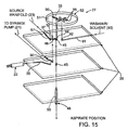
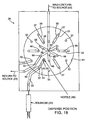
- the hybrid valve apparatus 20 includes a valve assembly 27 (FIGURES 15 and 16) movable between an aspiration condition (FIGURES 5, 9 and 10) and a dispensing condition (FIGURES 6, 11 and 12), and a manifold device 28 coupled to the valve assembly.
- the manifold device 28 includes a fluid aspiration conduit 30 having a first aspiration port 31 in fluid communication with the aspiration source 21.
- a second aspiration port 32 in selective fluid communication with the valve assembly 27 to selectively aspirate a liquid sample slug from the reservoir 23 into a discrete sample path 33 when the valve assembly 27 is in the aspiration condition.
- the manifold device 28 further includes a fluid dispensing conduit 35 having a first dispensing port 36 in fluid communication with the dispensing source 22, and a second dispensing port 37 in selective fluid communication with the valve assembly 27.
- the sample path 33 is fluidly coupled to the dispensing source 22 to selectively dispense at least one droplet 34 of the liquid sample slug therefrom.
- valve assembly 27 also fluidly decouples the sample path 33 from the aspiration source 21.
- valve assembly 27 fluidly couples the sample path 33 to the aspiration source 21, while simultaneously being out of fluid communication with the dispensing source 22.
- the hybrid valve apparatus provides a switching system which regulates fluid communication of the aspiration actuator and the dispensing actuator with the sample path containing the sample or reagent fluid. Whether the hybrid valve apparatus is in the aspiration condition or the dispensing condition, at no time will the valve assembly allow the sample path be in fluid communication with both the aspiration actuator and the dispensing actuator, simultaneously.
- This arrangement is beneficial in that the dispensing source can not be contaminated by the sampled fluid due to the isolating of the dispensing source from the sample path during the aspiration of the fluid into the sample path.
- each sample path is operatively switched between the aspiration actuator and the dispensing actuator enabling the micro-metered, non-contact parallel distribution of the reagents or sample fluid to the test site.
- the present invention is particularly suitable for transferring chemical or biochemical samples or reagents from an array of reservoir wells 38 of a conventional microtiter plate 40, i.e. 96 or 384 wells, to an array of higher-density test sites 25, i.e. a 1536-well microtiter plate, or for fabrication of a chip-based biological sensor (commonly referred to as a "microarray") used for performing gene expression or other screening experiments.
- the hybrid valve apparatus is adaptable for printing arrays wherein the distance between adjacent test sites 25, or test site pitch, is in the range of about 1 micron ( ⁇ m) to about 10,000 microns ( ⁇ m).
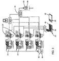
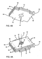
- the manifold device 28 includes a plurality of fluid aspiration conduits 30, corresponding fluid dispensing conduits 35 and corresponding sample paths 33, which cooperate for the parallel transfer of fluid from the fluid reservoir 23 to the corresponding test sites 25 (FIGURES 3, 4, 13 and 14).
- each fluid aspiration conduit 30 includes a first aspiration port 31 in fluid communication with a corresponding aspiration source or actuator, and an opposite second aspiration port 32 terminating at a stator face surface 41 of the manifold device 28.
- each fluid dispensing conduit 35 includes a first dispensing port 36 in fluid communication with a corresponding dispensing actuator 22, and an opposite second dispensing port 37 also terminating at the manifold stator face 41 as well.
- valve actuator assembly 27 When oriented in the aspiration condition (FIGURES 5, 9 and 10), the valve actuator assembly 27 permits selective fluid communication of the sample paths 33 with the corresponding second aspiration ports 32 of the aspiration conduits 30 at the stator face 41, while simultaneously preventing fluid communication with the corresponding second dispensing ports 37 of the dispensing conduits 35. Conversely, when the valve assembly is oriented in the dispensing condition (FIGURES 6, 11 and 12), the sample paths 33 are moved into selective fluid communication with the corresponding second dispensing ports 37 at the stator face, while simultaneously being moved out of fluid communication with the second aspiration ports 32.
- the present invention includes twelve (12) independent aspiration conduits 30, and dispensing conduits 35 communicating with corresponding sample paths 33.
- the hybrid valve apparatus 20 may simultaneously deliver sample or reagent fluid to twelve test sites.
- Other configurations, containing greater of lesser number of independent conduits are possible.
- the system can be configured for a one-to-one transfer of fluid, i.e., from each reagent reservoir to a designated test site.
- the hybrid valve apparatus can be configured for transferring sample or reagent fluids from a given number of reservoirs to a different number of test sites.
- the switching technology of the hybrid valve manifold device 28 can be designed such that fluid samples from multiple aspiration reservoirs 23 are dispensed on a single test site. Conversely, this manifolding can be adapted for depositing fluid from a single reservoir 23 to multiple test sites.
- the manifold device 28 is preferably sandwiched between a lower stator cover 42 and an upper stator ring 43 for stable support thereof.
- This assembly cooperates with a track or transport mechanism (not shown) which effects the relative movement between manifold device 28, the fluid reservoirs 23 and the test sites 25 (FIGURES 1 and 3).
- the entire hybrid valve apparatus 20 is transported between the microtiter plates 40 and the array of test sites 25.
- the hybrid valve apparatus 20 is adapted for simultaneously transferring multiple volumes of fluid sample or reagent to multiple chip test sites, a better understanding of the invention can be gained through a description of the operation thereof with respect to the transfer of the fluids from a single sample path 33 in the manifold device 28.
- the aspiration actuator 21 will be fluidly coupled to the manifold sample path 33, via the valve assembly 27, to aspirate sample fluid from the single reservoir 23 into the sample path.
- the sample path 33 will be switched, in fluid communication, to the dispensing conduit 35 for finely controlled dispensing of the sample fluid contained in the sample path 33.
- FIGURES 5, 6 and 9-12 intentionally depict a single set of fluid transfer elements.
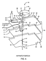
- each sample path 33 includes a primary passage portion 45 thereof defined by the manifold device 28.
- This primary passage portion 45 extends substantially vertically therethrough in a direction substantially parallel to an axis 44 of the hybrid valve apparatus 20.
- each primary passage 45 includes an upper communication port 46 terminating at the stator face 41, and a lower communication port 47.
- each primary passage 45 includes a corresponding nozzle member 48 extending outwardly from one of the lower communication ports 47.
- each nozzle member is removably mounted to the manifold device 28 which enables individual aspiration of the sample fluid therein (in the aspiration condition) or individual dispensing of the sample fluid therefrom (in the dispensing condition).
- a nozzle passage 50 extends longitudinally through the nozzle member 48 which inherently increases the volumetric capacity of the corresponding sample path 33.
- each of the aspiration conduits 30, the dispensing conduits 35 and the primary passages 45 include a respective port 32, 37 and 46 which terminates at the stator face 41 (FIGURE 7) for fluid communication with a rotor face 51 of a rotor element 52 of the valve assembly (FIGURE 8).
- each of the upper communication ports 46 of the primary passages 45 are equidistant from one another and are radially spaced about a rotational axis of the rotor element 52.
- each of the second aspiration ports 32 and each of the second dispensing ports 37 is also equidistant from one another and radially spaced about the rotational axis 44.
- FIGURE 7 best illustrates, however, that each of the second aspiration ports 32, which incidentally permit fluid communication with the corresponding aspiration actuator 21, are positioned at a radius from the rotation axis 44 smaller than that of the upper communication ports 46, while each of the second dispensing ports 37 are positioned at a radius larger than that of the upper communication ports.
- the upper communication ports 46, their corresponding second aspiration ports 32 and dispensing ports 37 are preferably collinearly aligned with a radial line intersecting the rotational axis 44.
- corresponding ports can be alternatively spaced and oriented without departing from the true spirit and nature of the present invention.
- collinear alignment between the corresponding ports 32, 37 and 46 is preferred, it is not a requirement for functionality of the manifold device, as will be apparent.
- valve assembly 27 and manifold device 28 are particularly suitable to the application of shear valve or flat face valve technology even though a rotary plug, a bank of 3-way solenoid valves, or MEMS device could be used.
- valve assembly 27 is illustrated having rotor element 52 which provides the contact or rotor face 51 in opposed sliding contact with the stator face 41 at a rotor-stator interface.
- This high pressure sliding contact between the stator face 41 and the rotor face 51 provide a selective switching function between each of the sample paths 33 (i.e., the primary passage 45 and nozzle passage 50) and the corresponding aspiration actuators 21 or dispensing actuators 22, depending upon whether the rotor element 52 of the valve assembly 27 is in the aspiration condition or the dispensing condition.
- both the rotor element 52 and the stator face element 53 are composed of conventional shear valve or flat face valve materials which are adapted to support the high pressure contact at the stator-rotor interface. Typical of these materials include ceramic and synthetic composition, many of which are proprietary in nature.
- the rotor element 52 is rotatably mounted to a shaft which in turn is connected to a gear reduction inside the actuator body 54. The gear reduction is then coupled to the motor shaft 55 of a conventional electric motor 56 applied in shear valve or flat face valve technology.
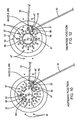
- the rotor element 52 of the valve assembly 27 provides a plurality of spaced-apart aspiration channels 57 and dispensing channels 58 which are slotted in the substantially planar rotor face 51 thereof.
- Each aspiration channel 57 and each dispensing channel 58 is elongated in shape, and extends generally along a radial line intersecting the rotational axis 44 of the rotor face 51. Further, the aspiration channels 57 and the dispensing channels 58 are equally spaced and are oriented in an alternating manner, relative one another.
- the rotor element 52 either reciprocates or rotates in one direction clockwise or counter clockwise to orient the valve assembly in the aspiration condition or the dispensing condition.
- the second dispensing ports 37 of the dispensing conduits 35 are dead-ended into the rotor face 51 of the rotor element 52.
- the dispensing actuators 22 are out of fluid communication with the corresponding sample paths 33.
- the rotor element 52 can be selectively rotated about rotational axis 44 to the dispensing condition.
- the radially extending dispensing channels 58 also slotted into the rotor face 51, are consequently rotated into collinear alignment with the corresponding upper communication ports 46 and the second dispensing ports 37 of the dispensing conduits 35 to provide a fluid communication path therebetween.
- the dispensing channels 58 thus, complete the fluid path between the corresponding sample path 33 and the corresponding dispensing actuator 22 to permit selective dispensing, via the dispensing actuator 22, of the fluid sample or reagent contained in the respective sample path 33.
- the second aspiration ports 32 of the dispensing conduits 35 are dead-ended into the rotor face 51 of the rotor element 52.
- the aspiration actuators 21 are out of fluid communication with their corresponding sample paths 33. Further, it will be appreciated that all twelve, or any number of, sample paths 33 can be simultaneously aspirated or dispensed.
- the shear valve and manifold device arrangement of the present invention provides an accurate switching functionality between the aspiration actuators and the dispensing actuators.
- switching capability is beneficial in that the full potential of the high speed, precision ink-jet style dispensing actuators can be exploited to dispense the sample fluids or reagents from the sample paths.
- the modular parallelism of system facilitates fabrication of non-contact devices, e.g. 24, 48, 96-tip, suitable to the expanding needs of the market.
- valve functionality of the present invention is particularly adaptable for flat face or shear valves
- other valve technologies are suitable such as solenoid valves, pinch valves and micromachined valves, actuated by mechanical, electrical or pneumatic means.
- each dispensing conduit 35 includes an independent dispensing source 22 fluidly coupled to its corresponding first dispensing port 36 thereof.
- the dispensing actuators 22 are preferably mounted to a corresponding dispensing actuator manifold device 28. These two opposed dispensing actuator manifolds separate and align the individual dispensing actuators into two sets of six actuators releasably mounted to the stator manifold device 28 as a unit.
- Each dispensing actuator 22 includes a delivery orifice 60 which is fluidly coupled to a corresponding first dispensing port 36 of the dispensing conduit 35.
- each dispensing actuator 22 typically delivers a metered pressure pulse using a pressure ranging from about 6.9(10) 3 N/m 2 to about 138(10) 3 N/m 2 , and having a duration ranging from about (10) -6 seconds to about 10 seconds.
- the dispensing actuator 22 is provided by a conventional ink-jet style printing valve or pump designed for drop-on-demand printing.
- Ink-jet style printing valves/pumps for drop-on-demand printing including thermal, solenoid and piezoelectric types, are commercially available and well known in the art.
- the Lee Company of Essex, Connecticut manufactures a solenoid-based ink-jet valve (Model No. INKX0502600AB) which is suitable for use with the present invention.
- conventional syringe pumps may be employed for metering as well.
- ink-jet drop-on-demand printing technology provides significant advantages visa-vis known systems for printing microarrays.
- the ability to deliver independent, short-duration, pressure pulses associated with ink-jet print valves enables the non-contact tunable delivery of reagent sample volumes in the range of about (10) 10 to about (10) -12 liters.
- at least one droplet of sample or reagent fluid is ejected from the manifold sample path through the corresponding nozzle member 48 onto substrate surface 26.
- non-contact refers to the lack of contact between the dispense manifold and nozzles, and the target substrate during deposition.
- the fluid is communicated through channels micromachined into an ink-jet style printhead - such as those commonly used in desktop and industrial printers.
- these ink-jet drop-on-demand dispensing actuators are coupled to digitally regulated hydraulic pressure systems (not shown). These systems enable precise manipulation of hydraulic pressure supplied to the dispensing actuators expanding the dynamic range of the system. An added benefit is the ability to quickly change the pressure range to compensate for differences in samples due to particulates or viscosity.
- the aspiration source 21, on the other hand, are preferably provided by individual aspiration actuators 21 fluidly coupled to a corresponding first aspiration port 31 through tubing 61.
- These tubes 61 which are preferably inert plastic or the like having an inner diameter in the range of 0.2 mm to about 3.0 mm, are also separated into two banks of six units and each have a distal end coupled to a tubing array manifold 62.
- these opposed tubing array manifolds 62 are mounted to the stator manifold device 28 as a unit.
- the aspiration actuator 21 is provided by an external metering device such as a syringe-type pump or a diaphragm pump, or by a pressurized source delivering a positive or negative pressure to the aspiration conduits 30.
- an external metering device such as a syringe-type pump or a diaphragm pump, or by a pressurized source delivering a positive or negative pressure to the aspiration conduits 30.
- Typical of these aspiration devices is Model # 2009D provided by Innovadyne Technologies, Inc., Rohnert Park, CA.
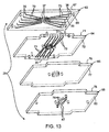
- the manifold device 28 is comprised of a plurality of stacked plate members 63-66 which collectively cooperate to channel the sample fluids from the reservoir wells to the designated test sites 25, via the valve assembly 27.
- the manifold device 28 defines a plurality of primary passages 45, aspiration conduits 30 and dispensing conduits 35 each of which includes a communication port terminating at the stator face for communication with the valve assembly 27.
- these individual conduits are independent of one another, fabrication is difficult for such a small scale.
- the diameter of these fluid passages is on the order of about 0.001 mm to about 1.0 mm.
- these conduits and passages must be capable of accommodating the relatively high pressure pulses of the dispensing actuators 22 which as mentioned have a range from about 6.9(10) 3 N/m 2 to about 138(10) 3 N/m 2 , and have a duration in the range from about (10) -6 seconds to about (10) 1 seconds.
- the plate members 63-66 are preferably rectangular in shape, each having a substantially planar topside and an opposed bottom side. More particularly, the manifold device 28 includes a first plate member 63 having a topside surface 67 upon which the disk-shaped stator face element 53, defining the stator face 41, is supported. On an opposite side of the topside surface 67 of the first plate member 63 is a bottomside surface 68 upon which a plurality of horizontally extending dispensing grooves 70 are formed. These grooves are preferably about 0.3 mm in width and are about 1.0 mm deep into the bottomside surface 68, depending upon the particular application.
- a corresponding first dispensing port 36 extends vertically into the first plate member 63 from the topside surface 67 to the bottomside surface 68 where it intersects one end of a corresponding dispensing groove 70.
- a corresponding second dispensing port 37 extends vertically into the stator face element 53 and first plate member 63 from the stator face 41 to the bottomside surface 68 where it intersects an opposite end of a corresponding dispensing groove 70.
- a substantially planar topside surface 71 of the second plate member 64 is affixedly lamination or diffusion bonded to the bottomside surface 68 of the first plate member 63 at a first plate/second plate interface.
- the diffusion bonded second plate member topside surface 71 effectively seals the dispensing grooves 70 extending into the bottomside surface 68 of the first plate member 63 to form the corresponding dispensing conduits 35.
- first dispensing ports 36 can be positioned at a plurality of locations along the topside surface of the first plate member without departing from the true spirit and nature of the present invention.
- the aspiration conduits 30 could also have been defined at the first plate/second plate interface.
- the aspiration conduits 30 are preferably formed at a separate second plate/third plate interface between the second plate member 64 and a third plate member 65.
- the bottomside surface 72 of the second plate member preferably incorporates a plurality of horizontally extending aspiration grooves 73 (FIGURES 13 and 14) which are preferably about 0.5 mm in width and are about 0.25 mm deep.
- a corresponding first aspiration port 31 extends vertically into the second plate member 64 from the topside surface 71 to the bottomside surface 72 thereof where it intersects one end of a corresponding aspiration grooves 73.
- the second plate member includes a pair of opposed wing portions 75 which extend beyond the peripheral edge of the first plate member 63.
- these wing portions 75 are adapted to accommodate the mounting of the tubing array manifolds 62 thereto.
- these aligned vertical passages extend from the stator face 41 of the stator face element 53 through both the first plate member 63 and the second plate member 64 to the bottomside surface 72 thereof where it intersects an opposite end of a corresponding aspiration groove 73.
- a substantially planar topside surface 76 of the third plate member 65 is affixedly coupled to the bottomside surface 72 of the second plate member 64 at the second plate/third plate interface.
- the third plate topside surface 76 can be laminated to the second plate bottomside surface 72 to effectively seal the aspiration grooves 73 to form the corresponding aspiration conduits 30.
- the circular pattern of the upper communication port 46 extend vertically through the stator element 53.
- the first plate member 63, the second plate member 64 and the third plate member 65 also include corresponding co-axially aligned passage components to collectively form the primary passages 45 of the sample paths 33 when the manifold plate members are laminated together.
- the transverse cross-sectional area of primary passages 45 are on the order of about 0.2 mm 2 to about 0.8 mm 2 from the stator face 41 to a bottomside surface 77 of the third plate member 65.
- a fourth plate member 66 is required to reorient the circular pattern of the upper communication port 46 at the bottomside surface 77 of the third plate member 65 to a rectangular pattern of the lower communications ports 47, which conforms to the spacing of the array of reservoir wells 38 of the microtiter plate 40 and test sites 25, a fourth plate member 66 is required.
- a fourth topside surface 76 of the fourth plate includes a plurality of horizontally extending repositioning grooves 79. These grooves 79 are preferably about 0.5 mm in width and are about 0.25 mm deep into the topside surface 76 of the fourth plate member 66.
- a corresponding lower communication port 47 extends vertically into the fourth plate member 66 from a bottomside surface 80 to the topside surface 78 thereof where it intersects one end of a corresponding repositioning groove 79.
- the other end of the repositioning groove 79 is aligned with the corresponding primary passage 45 terminating at the bottomside surface 77 of the third plate member 65.
- the fourth plate topside surface 78 can be diffusion bonded to the third plate bottomside surface 77 to effectively seal the repositioning grooves 79 to form another portion of the sample path 33.
- each lower communication port 47 of the primary passage 45 fluidly coupled to each lower communication port 47 of the primary passage 45 is a corresponding nozzle member 48 having a nozzle passage 50 extending therethrough.
- the elongated nozzle member 48 includes a distal tip portion 81 suitably dimensioned to extend into a targeted reservoir well 38, in aspiration condition, to aspirate sample or reagent fluid into the sample path 33.
- the 2 x 6 array of nozzles are spaced apart to conform with the array of reservoir wells and test sites 25 for simultaneous aspiration and dispensing. They can also be redistributed to other formats such as 1 x 12.
- the diameter of the nozzle 50 passages abruptly changes to a smaller diameter by means of an orifice, such as a jeweled orifice.
- This change in diameter is beneficial in that it facilitates ejection of the sample fluids from the tip when a pressure pulse is delivered by the corresponding dispensing actuator 22.
- system fluid reservoirs 82, 83, containing conventional mobile phase fluid 85, 86, are supplied to the aspiration actuators 21 and the dispensing actuators 22 as a driving fluid.
- the aspiration actuators 21 can be first employed to purge the entire path from the first aspiration port 31 of the aspiration conduit all the way to the corresponding dispensing orifice of the tip 81 of the nozzle member 48.
- clean mobile phase fluid replaces any sample or reagent fluid from previous operations.
- the transport mechanism (not shown) is then operated to position the hybrid valve assembly 27 at the reservoir wells 38 where the designated nozzle tips 81 are submersed in the targeted reservoir wells. Operation of one or more of the syringe pumps 21 draw the sample or reagent fluids into the corresponding sample path 33 in the manifold device 28. The volume of fluid aspirated into the corresponding sample path 33, thus, can be accurately metered.
- the transport mechanism can move the hybrid valve assembly 27 to the test sites 25, while the electric motor 56 and drive train 54 rotates the rotor element 52 from the aspiration condition to the dispensing condition.
- the aspiration channels 57 in the rotor face 51 are moved out of fluid coupling to the upper communication ports 46 of the primary passages 45, while the dispensing channels 58 in the rotor face 51 are moved to fluidly couple the second dispensing ports 37 of the dispensing conduits 35 with the corresponding communication ports 46.
- the second dispensing port 37 of the dispensing conduit 35 is dead-ended against the rotor face 51, while in the dispensing position, the second aspiration port 32 of the aspiration conduit 30 is dead-ended against the rotor face 51.
- the mobile phase fluid which is preferably substantially similar to that supplied to the aspiration actuators, is fluidly coupled to the corresponding dispensing channels 58 in the rotor face 51 to selectively dispense the sample fluids from the corresponding nozzle tips 81. Accordingly, cross-contamination is minimized to the mobile phase fluids contained in the corresponding dispensing channels 58. This assures that the dispensing conduits 35 can be substantially maintained free of contamination of any sample or reagent fluids.
- the nozzle passages 50 and corresponding primary passages 45 may only be employed to dispense the sample or reagent fluid from the sample path 33.
- the nozzle member 48 thus, will not be utilized to aspirate the targeted fluid into the sample path from the source plate. Accordingly, as viewed in the embodiments of FIGURES 15 and 17, the hybrid valve assembly can load the sample path 33 through means other than the nozzle members 48, while maintaining the isolation of the sample path from the dispensing actuator, in the aspiration condition (FIGURES 15 and 17), and isolation of the sample path from the aspiration actuator, in the dispensing condition (FIGURES 16 and 18).
- the manifold body in this configuration includes a source conduit, generally designated 87, having an upper communication opening 88 terminating at the stator face 41, and an opposite end in fluid communication with the source reservoir 23.
- a source conduit generally designated 87
- the contact or rotor face 51 of the valve body or rotor element 52 includes a sample channel 90 which, in the aspiration condition, fluidly couples the second aspiration port 32 of the aspiration conduit 30 to the upper communication opening 88 of the source conduit 87.
- the aspiration actuator 21 is fluidly coupled to the source reservoir through the sample channel 90 formed in the rotor face 51.
- the reagent or sample fluid can be drawn into the sample path 33 by way of the source conduit 87 in the manifold body 28.
- the corresponding second dispensing port 37 of the dispensing conduit 35 is dead-ended into the rotor face 51, and thereby out of fluid communication with the sample path (FIGURE 17).
- valve assembly 27 can be moved to the dispense position of FIGURES 16 and 18.
- the rotor element 52 of the valve assembly is rotated about rotational axis 44 for movement from the aspiration condition to the dispense condition.
- the sample channel 90 containing the reagent or sample fluid, is co-aligned with and moved into the fluid communication with the second dispensing port 37 of the dispensing conduit 35 and the upper communication port 46 of the primary passage 45.
- the dispensing actuator 22 is therefore fluidly coupled to the sample path 33 to fluidly dispense the reagent or sample fluid out of the nozzle member 48. Moreover, to isolate the aspiration actuator 21 from the sample path 33, the corresponding aspiration port 32 of the aspiration conduit 30 is dead-ended into the rotor face 51, and thereby out of fluid communication with the sample path (FIGURE 18).
- the dispensable volume of the sample path 33 is essentially the same as that of the sample channel 90.
- the rotor element 52 rotates to the dispensing condition (FIGURES 16 and 18)
- only the sample or reagent fluid contained in the sample channel 90 is fluidly accessible to the dispensing actuator. It will be understood, however, that volumetric quantities less than the full volume of the sample channel 90 may be dispensed through precision operation of the dispensing actuator 22.
- each sample channel 90 is slotted into the substantially planar rotor face 51 of the rotor element 52. Further, each equally spaced sample channel 90 is elongated in shape, and extends generally along a radial line intersecting the rotational axis 44 of the rotor face 51. Accordingly, at the rotor-stator interface (i.e., the high pressure sliding contact between the stator face 41 and the rotor face 51), the rotor element 52 either reciprocates or rotates in one direction clockwise or counter clockwise to orient the valve assembly in the aspiration condition or the dispensing condition.
- sample channels 90 preferably have a length in the range of about 1.0 mm to about 6.0 mm, and have a transverse cross-sectional area of about 0.3 mm 2 to about 1 mm 2 . Accordingly, the volumetric capacity of the sample channel 90 is preferably in the range of about 0.5 ⁇ l to about 2.0 ⁇ l.
- the primary passage 45 and the nozzle passage 50 of the outlet preferably has a volume in the range of 0.1 ⁇ l to about 2.0 ⁇ l.
- the separation of the aspiration duty from the nozzle member 48 has several functional advantages.
- One benefit is that the total volume of sample is contained in the sample channel 90. Unused sample or reagent may be returned to the source, during dispense (Fig 18) via the source path 23 significantly reducing sample and reagent waste volumes.
- An added benefit is that the nozzle member 48 may be greatly reduced in length to shorten the dispense path and pre-dispensing.
- the aspiration inlets (not shown), fluidly coupled to source conduits 87, can be set at one spacing and order (e.g., 96 well format), while the nozzle members 48 can be set to a different spacing and order (e.g., 1536 well format). Accordingly, the aspiration versatility is substantially increased. For example, some applications require individual manipulation of aspiration tips, such as applications that reformat individual positive samples to one destination plate from a multiplicity of positive and negative samples in a source plate.
- the transverse cross-sectional dimension of the aspiration and source conduits 30, 87, on the aspiration side can be different from that of the dispensing conduits 35 and the primary passages 45 in the manifold device 28 and the nozzle passages 50 of the nozzle member 48, on the dispensing side.
- the permissible wider cross-sectional dimension of the aspiration inlet allows for the inclusion of filtering devices.
- filtering devices For example, by incorporating a filter on the inlet side, small particulates in the reagent or sample fluid that would normally clog, and render useless, a small bore nozzle can be removed.
- a filter could be exchangeable and would contain a high surface area allowing for filtering of particulates without frequent clogging.
- Typical of such filtering devices include frits commonly used in solid phase extraction or liquid chromatography devices.
- this embodiment of the present invention may further include a flush passage 91 in the manifold device 28 having an upper central flush port 92 terminating at the stator face 41, and an opposite end in fluid communication with a flush source 93.
- the central flush port 92 is aligned substantially co-axial with the rotational axis 44 of the rotor element 52 for continuous fluid communication with a flush channel 95 slotted in the rotor face 51 (FIGURE 19).
- this flush channel 95 in the rotor element 52 is fluidly couples the flush port 92 of the flush passage 91 to the upper communication port 46 of the corresponding primary passage 45.
- the primary passages 45 and the nozzle passages 50 may be simultaneously flushed or cleaned with wash fluid or the like from the wash source 93.
- the flush channel 95 slotted in the rotor face fluidly couples the flush port 92 of the flush passage 91 to the upper communication opening 88 of the source conduit 87. Therefore, when the reagent or sample fluid is being dispensed from the sample path 33 through the corresponding nozzle member 48, unused sample or reagent could be returned to the source reservoir 23 and the aspirate path flushed.
- the flush channel 95 is provided by a plurality of equally spaced elongated slots which extend generally along a radial line intersecting the rotational axis 44 of the rotor face 51. These radially extending flush channels intersect at the rotational axis 44 so that the flush channels are in continuous fluid communication with the central flush port 92.
- the upper communication ports 46 of the primary passages 45 and the upper communication openings 88 of the source conduits 87 are alternately spaced about the rotational axis 44. Accordingly, each rotation movement of the rotor element 52 between the aspiration condition (FIGURES 15 and 17) and the dispensing condition (FIGURES 16 and 18) alternates fluid communication with the nozzle passages 50 and the source conduits 87.
- the rotor element 52 either reciprocates or rotates in one direction clockwise or counter clockwise to orient the valve assembly in the aspiration condition or the dispensing condition.
Landscapes
- General Engineering & Computer Science (AREA)
- Engineering & Computer Science (AREA)
- Chemical & Material Sciences (AREA)
- Mechanical Engineering (AREA)
- Dispersion Chemistry (AREA)
- Life Sciences & Earth Sciences (AREA)
- Physics & Mathematics (AREA)
- Analytical Chemistry (AREA)
- Biochemistry (AREA)
- General Health & Medical Sciences (AREA)
- General Physics & Mathematics (AREA)
- Immunology (AREA)
- Pathology (AREA)
- Health & Medical Sciences (AREA)
- Organic Chemistry (AREA)
- Chemical Kinetics & Catalysis (AREA)
- Hydrology & Water Resources (AREA)
- Automatic Analysis And Handling Materials Therefor (AREA)
- Sampling And Sample Adjustment (AREA)
- Loading And Unloading Of Fuel Tanks Or Ships (AREA)
- Apparatus Associated With Microorganisms And Enzymes (AREA)
- Catching Or Destruction (AREA)
- Feeding, Discharge, Calcimining, Fusing, And Gas-Generation Devices (AREA)
Claims (15)
- Hybride Ventilvorrichtung (20) zur Verwendung mit einem Ansaugbetätiger (21) und einem Spendebetätiger (22), um eine übertragung eines Flüssigkeitsprobenpropfens aus einem Speicher (23) zu einer Untersuchungsstelle (25) auf einer Substratoberfläche (26) zu ermöglichen, umfassend:eine Ventilanordnung (27), die zwischen einem Ansaugzustand und einem Spendezustand beweglich ist;eine Verbindungsstruktur (48), die eine Spendeöffnung aufweist; undeine Einzelblock-Fluidverteilungsverteilervorrichtung (28), die einen Flüssigkeitsansaugkanal (30) bereitstellt, der eine Treibflüssigkeit enthält und eine erste Ansaugöffnung (31) in Flüssigkeitsverbindung mit dem Ansaugbetätiger (21) und eine zweite Ansaugöffnung (32) in selektiver Flüssigkeitsverbindung mit der Ventilanordnung (27) aufweist, um selektiv einen Flüssigkeitsprobenpfropfen aus dem Speicher (23) durch die Spendeöffnung der Verbindungsstruktur (48) anzusaugen, wobei ein diskreter Probenpfad (37) festgelegt wird, der sich zur Flüssigkeitsverbindung mit der Ventilanordnung von der Spendeöffnung (36) aus und durch mindestens einen Teil der Verteilervorrichtung (28) erstreckt, wenn sich die Ventilanordnung im Ansaugzustand befindet, wobei die Verteilervorrichtung (28) weiter einen Flüssigkeitsspendekanal (35) bereitstellt, der eine erste Spendeöffnung (36) in Flüssigkeitsverbindung mit dem Spendebetätiger und eine zweite Spendeöffnung (37) in selektiver Flüssigkeitsverbindung mit der Ventilanordnung auf weist, um selektiv mindestens ein Tröpfchen des Flüssigkeitsprobenpfropfens aus der Spendeöffnung der Verbindungsstruktur zu spenden, wenn sich die Ventilanordnung im Spendezustand befindet,bei der sich im Ansaugzustand der Probenpfad außer Flüssigkeitsverbindung mit dem Spendebetätiger befindet und sich im Spendezustand der Probenpfad außer Flüssigkeitsverbindung mit dem Ansaugbetätiger befindet.
- Hybride Ventilvorrichtung nach Anspruch 1, bei der
das durch mindestens einen Teil des Verteilers (28) einen primären Durchlassteil (45) des Probenpfades einschließt. - Hybride Ventilvorrichtung nach Anspruch 2, bei der
die Verbindungsstruktur (48) ein Düsenelement einschließt, das an einer Spendeöffnung endet, die ausgebildet ist, um den Probenpfropfen anzusaugen und das Tröpfchen abzugeben. - Hybride Ventilvorrichtung nach Anspruch 3, bei der
der primäre Durchlassteil (45) von einer Querschnittsfläche von 0,2 mm2 bis 0,8 mm2 ist. - Hybride Ventilvorrichtung nach Anspruch 2, bei der
die Verteilervorrichtung eine die zweite Ansaugöffnung und die zweite Spendeöffnung enthaltende Statorfläche (41) einschließt, und die Ventilanordnung einen Ventilkörper mit einer Kontaktfläche (51) einschließt, welche die Statorfläche an einer Statorkontaktgrenzfläche verschiebbar berührt, für einen abgedichteten Verschiebekontakt zwischen
dem Ansaugzustand, der die zweite Ansaugöffnung fluidisch mit dem primären Durchlassteil (45) des Probenpfaden verbindet, und
dem Spendezustand, der die zweite Spendeöffnung fluidisch mit dem primären Durchlassteil (45) des Probenpfades verbindet. - Hybride Ventilvorrichtung nach Anspruch 5, bei der
die Kontaktfläche (51) des Ventilkörpers einschließt:einen Ansaugkanal (57) der im Ansaugzustand die zweite Ansaugöffnung fluidisch mit dem primären Durchlassteil des Probenpfades durch den Ansaugkanal verbindet, undeinen Spendekanal (58), der im Spendezustand die zweite Spendeöffnung fluidisch mit dem primären Durchlassteil (45) des Probenpfades durch den Spendekanal verbindet. - Hybride Ventilvorrichtung nach Anspruch 6, bei der
der primäre Durchlassteil (45) des Probenpfades eine an der Statorfläche endende obere Verbindungsöffnung (46) einschließt, die sich im Ansaugzustand in Flüssigkeitsverbindung mit dem Ansaugkanal und im Spendezustand in Flüssigkeitsverbindung mit dem Spendekanal befindet. - Hybride Ventilvorrichtung nach Anspruch 7, bei der
die verbindungsstruktur (48) ein an der Spendeöffnung endendes Düsenelement einschließt, um den Probenpfropfen anzusaugen und das Tröpfchen abzugeben. - Hybride ventilvorrichtung nach Anspruch 8, bei der
mindestens eines von dem ventilkörper und der Verteilervorrichtung um eine senkrecht zur statorkontaktgrenzfläche verlaufende Drehachse drehbar ist, um die Kontaktfläche, den Ansaugkanal und den Spendekanal relativ zur Statorfläche zwischen dem Ansaugzustand und dem Spendezustand zu verdrehen. - Hybride Ventilvorrichtung nach Anspruch 9, bei der
der Spendekanal und der Ansaugkanal in einer Richtung radial um die Drehachse verlaufen. - Hybride Ventilvorrichtung nach einem vorangehenden Anspruch, weiter einschließend:ein digital geregeltes hydraulisches Drucksystem in Flüssigkeitsverbindung mit dem Spendebetätiger für einen Präzisionsbetrieb desselben.
- Verfahren zum Überführen einer Flüssigkeitsprobe aus einem Flüssigkeitsprobenspeicher (23) zu einer Untersuchungsstelle auf einem Zielsubstrat, umfassend:Bereitstellen einer Einzelblock-Fluidverteilungsverteilervorrichtung (28), die einen Flüssigkeitsansaugkanal (30) festlegt, der eine Treibflüssigkeit enthält und eine erste Ansaugöffnung (31) in Flüssigkeitsverbindung mit einem Ansaugbetätiger (21) und eine zweite Ansaugöffnung (32) in Flüssigkeitsverbindung mit einer ventilanordnung (27) aufweist, wobei die Verteilervorrichtung weiter einen Flüssigkeitsspendekanal festlegt, der eine Treibflüssigkeit enthält und eine erste Spendeöffnung (36) in Flüssigkeitsverbindung mit einem Spendebetätiger (22) und eine zweite Spendeöffnung (37) in Flüssigkeitsverbindung mit der Ventilanordnung aufweist;Positionieren der Ventilanordnung in einem Ansaugzustand, wobei der Ansaugbetätiger fluidisch mit einem diskreten Probenpfad verbunden wird, der sich von einer einen diskreten Probenpfad festlegenden verbindungsstruktur (48) aus und durch mindestens einen primären Durchlassteil der Verteilervorrichtung (28) in Fluidverbindung mit der Ventilanordnung erstreckt, und wobei der Spendebetätiger fluidisch vom Probenpfad getrennt wird;im Ansaugzustand Betätigen des Ansaugbetätigers, um einen Flüssigkeitsprobenpfropfen aus dem Probenspeicher (23) durch die Spendeöffnung (36) in den Probenpfad anzusaugen;Positionieren der Ventilanordnung in einem Spendezustand, wobei der Spendebetätiger fluidisch mit dem Probenpfad verbunden wird, und der Ansaugbetätiger fluidisch von demselben Pfad getrennt wird; undim Spendezustand Betätigen des Spendebetätigers, um mindestens ein Tröpfchen des Flüssigkeitsprobenpfropfens durch die Spendeöffnung aus dem Probenpfad heraus abzugeben.
- Verfahren nach Anspruch 12, bei dem
der primäre Durchlassteil der Verteilervorrichtung eine an einer Statorfläche des Verteilers endende obere Verbindungsöffnung (46) aufweist, wobei die Statorfläche weiter die zweite Ansaugöffnung und die zweite Spendeöffnung enthält. - Verfahren nach Anspruch 13, bei dem
das Positionieren der Ventilanordnung in den Ansaugzustand oder den Spendezustand einschließt, eine Kontaktfläche (51) der ventilanordnung an einer Statorkontaktgrenzfläche verschiebbar in Eingriff gegen die Statorfläche der Verteilervorrichtung (28) zu bringen, um den Ansaugbetätiger fluidisch mit dem primären Durchlassteil des Probenpfades zu verbinden bzw. um den Spendebetätiger fluidisch mit dem primären Durchlassteil des Probenpfades zu verbinden. - Verfahren nach Anspruch 14, bei dem
das verschiebbar in Eingriff bringen ein verdrehen eines Ansaugkanals (57) und eines Spendekanals (58) in der Kontaktfläche der Ventilanordnung um eine Drehachse derselben relativ zur Statorfläche einschließt, um
im Ansaugzustand die obere Verbindungsöffnung durch den Ansaugkanal fluidisch mit der zweiten Ansaugöffnung zu verbinden, und
im Spendezustand die obere verbindungsöffnung durch den Spendekanal fluidisch mit der zweiten Spendeöffnung zu verbinden.
Priority Applications (2)
| Application Number | Priority Date | Filing Date | Title |
|---|---|---|---|
| EP06020778.4A EP1746316A3 (de) | 2000-10-11 | 2001-09-28 | System mit Hybridventil und Verfahren zur Flussigkeitshandhabung |
| EP10182540.4A EP2333387A3 (de) | 2000-10-11 | 2001-09-28 | System mit Hybridventil und Verfahren zur Flussigkeitshandhabung |
Applications Claiming Priority (2)
| Application Number | Priority Date | Filing Date | Title |
|---|---|---|---|
| US689548 | 2000-10-11 | ||
| US09/689,548 US6852291B1 (en) | 2000-10-11 | 2000-10-11 | Hybrid valve apparatus and method for fluid handling |
Related Child Applications (2)
| Application Number | Title | Priority Date | Filing Date |
|---|---|---|---|
| EP10182540.4A Division EP2333387A3 (de) | 2000-10-11 | 2001-09-28 | System mit Hybridventil und Verfahren zur Flussigkeitshandhabung |
| EP06020778.4A Division EP1746316A3 (de) | 2000-10-11 | 2001-09-28 | System mit Hybridventil und Verfahren zur Flussigkeitshandhabung |
Publications (3)
| Publication Number | Publication Date |
|---|---|
| EP1197693A2 EP1197693A2 (de) | 2002-04-17 |
| EP1197693A3 EP1197693A3 (de) | 2003-03-26 |
| EP1197693B1 true EP1197693B1 (de) | 2006-11-22 |
Family
ID=24768948
Family Applications (3)
| Application Number | Title | Priority Date | Filing Date |
|---|---|---|---|
| EP01308303A Expired - Lifetime EP1197693B1 (de) | 2000-10-11 | 2001-09-28 | System mit Hybridventil und Verfahren zur Flussigkeitshandhabung |
| EP10182540.4A Withdrawn EP2333387A3 (de) | 2000-10-11 | 2001-09-28 | System mit Hybridventil und Verfahren zur Flussigkeitshandhabung |
| EP06020778.4A Withdrawn EP1746316A3 (de) | 2000-10-11 | 2001-09-28 | System mit Hybridventil und Verfahren zur Flussigkeitshandhabung |
Family Applications After (2)
| Application Number | Title | Priority Date | Filing Date |
|---|---|---|---|
| EP10182540.4A Withdrawn EP2333387A3 (de) | 2000-10-11 | 2001-09-28 | System mit Hybridventil und Verfahren zur Flussigkeitshandhabung |
| EP06020778.4A Withdrawn EP1746316A3 (de) | 2000-10-11 | 2001-09-28 | System mit Hybridventil und Verfahren zur Flussigkeitshandhabung |
Country Status (6)
| Country | Link |
|---|---|
| US (3) | US6852291B1 (de) |
| EP (3) | EP1197693B1 (de) |
| JP (1) | JP4229605B2 (de) |
| AT (1) | ATE346256T1 (de) |
| CA (1) | CA2358622C (de) |
| DE (1) | DE60124653T2 (de) |
Cited By (1)
| Publication number | Priority date | Publication date | Assignee | Title |
|---|---|---|---|---|
| US11773999B2 (en) | 2017-01-27 | 2023-10-03 | Agilent Technologies, Inc. | Fluid valve having a coating containing gold and/or platinum |
Families Citing this family (61)
| Publication number | Priority date | Publication date | Assignee | Title |
|---|---|---|---|---|
| US20030215957A1 (en) * | 1998-02-20 | 2003-11-20 | Tony Lemmo | Multi-channel dispensing system |
| US7135146B2 (en) | 2000-10-11 | 2006-11-14 | Innovadyne Technologies, Inc. | Universal non-contact dispense peripheral apparatus and method for a primary liquid handling device |
| US6852291B1 (en) * | 2000-10-11 | 2005-02-08 | Innovadyne Technologies, Inc. | Hybrid valve apparatus and method for fluid handling |
| WO2002089670A1 (en) * | 2001-05-10 | 2002-11-14 | Chempaq A/S | Device for sampling small and precise volumes of liquid |
| WO2003023410A1 (en) * | 2001-09-07 | 2003-03-20 | Innovadyne Technologies, Inc. | Secondary liquid dispensing module for liquid handling system |
| US6748975B2 (en) | 2001-12-26 | 2004-06-15 | Micralyne Inc. | Microfluidic valve and method of manufacturing same |
| JP2005516220A (ja) * | 2002-01-25 | 2005-06-02 | イノベイダイン・テクノロジーズ・インコーポレーテッド | 低容量かつ非接触な液体の分注方法 |
| US7105131B2 (en) * | 2002-09-05 | 2006-09-12 | Xerox Corporation | Systems and methods for microelectromechanical system based fluid ejection |
| US6736370B1 (en) * | 2002-12-20 | 2004-05-18 | Applied Materials, Inc. | Diaphragm valve with dynamic metal seat and coned disk springs |
| AU2003303439A1 (en) * | 2002-12-20 | 2004-07-22 | Applied Materials, Inc. | Micromachined intergrated fluid delivery system |
| US7097070B2 (en) | 2003-08-15 | 2006-08-29 | Protedyne Corporation | Method and apparatus for handling small volume fluid samples |
| US20050232821A1 (en) * | 2003-09-19 | 2005-10-20 | Carrillo Albert L | High density plate filler |
| US20060233673A1 (en) * | 2003-09-19 | 2006-10-19 | Beard Nigel P | High density plate filler |
| US7407630B2 (en) * | 2003-09-19 | 2008-08-05 | Applera Corporation | High density plate filler |
| US20060233671A1 (en) * | 2003-09-19 | 2006-10-19 | Beard Nigel P | High density plate filler |
| US7998435B2 (en) * | 2003-09-19 | 2011-08-16 | Life Technologies Corporation | High density plate filler |
| US20050226782A1 (en) * | 2003-09-19 | 2005-10-13 | Reed Mark T | High density plate filler |
| US20070014694A1 (en) * | 2003-09-19 | 2007-01-18 | Beard Nigel P | High density plate filler |
| US20050220675A1 (en) * | 2003-09-19 | 2005-10-06 | Reed Mark T | High density plate filler |
| US20060272738A1 (en) * | 2003-09-19 | 2006-12-07 | Gary Lim | High density plate filler |
| US8277760B2 (en) * | 2003-09-19 | 2012-10-02 | Applied Biosystems, Llc | High density plate filler |
| DE602004004612T2 (de) * | 2004-05-22 | 2007-05-24 | Agilent Technologies, Inc. (n.d. Ges. d. Staates Delaware), Santa Clara | Bauteil eines mikrofluidischen Ventils |
| WO2007044606A1 (en) * | 2005-10-06 | 2007-04-19 | Haynes Enterprise, Inc. | An electroluminescent display apparatus for an inflatable device and method |
| WO2008061000A2 (en) * | 2006-11-09 | 2008-05-22 | Parker-Hannifin Corporation | Pneumatic valve control assembly |
| US20080134806A1 (en) * | 2006-12-06 | 2008-06-12 | Agamatrix, Inc. | Container system for dispensing a liquid |
| EP2136911A2 (de) | 2007-01-19 | 2009-12-30 | Biodot, Inc. | Systeme und verfahren für hochgeschwindigkeitsarraydruck und -hybridisierung |
| WO2008106613A2 (en) * | 2007-02-28 | 2008-09-04 | Waters Investments Limited | Liquid-chromatography apparatus having diffusion-bonded titanium components |
| US20090104078A1 (en) * | 2007-10-18 | 2009-04-23 | Matrix Technologies Corporation | Apparatus and method for dispensing small volume liquid samples |
| CA2722190A1 (en) * | 2008-04-21 | 2009-10-29 | Swapsol Corp. | Hydrogen sulfide conversion to hydrogen |
| DE202009007800U1 (de) * | 2009-06-04 | 2009-08-20 | Bürkert Werke GmbH & Co. KG | Modulares Fließinjektions-Analysesystem |
| WO2012042226A2 (en) | 2010-10-01 | 2012-04-05 | Oxford Nanopore Technologies Limited | Biochemical analysis apparatus and rotary valve |
| CN103429348B (zh) | 2011-01-21 | 2016-03-09 | 拜奥-多特公司 | 具有纵向变换器和可替换毛细管的压电分配器 |
| US9140376B2 (en) | 2011-05-13 | 2015-09-22 | Siemens Healthcare Diagnostics Inc. | Rotary shear valve with three-point stator seating |
| GB2492955A (en) | 2011-07-13 | 2013-01-23 | Oxford Nanopore Tech Ltd | One way valve |
| CN103946544B (zh) | 2011-09-15 | 2017-06-06 | 牛津纳米孔技术有限公司 | 泵 |
| US8813785B2 (en) * | 2012-01-09 | 2014-08-26 | Promochrom Technologies Ltd. | Fluid selection valve |
| US9481477B2 (en) * | 2012-09-17 | 2016-11-01 | Life Technologies Corporation | Fluid manifold system with rotatable port assembly |
| ES2939140T3 (es) * | 2013-08-08 | 2023-04-19 | Illumina Inc | Sistema de fluido para el suministro de reactivos a una celda de flujo |
| US9057671B1 (en) | 2013-12-17 | 2015-06-16 | Alessi Technologies, Inc. | System and method for biological specimen mounting |
| US10119889B2 (en) | 2013-12-17 | 2018-11-06 | Aquaro Histology, Inc. | System and method for mounting a specimen on a slide |
| US9605669B2 (en) | 2014-03-19 | 2017-03-28 | Graco Fluid Handling (A) Inc. | Multi-port metering pump assembly and related methods |
| WO2016004171A1 (en) | 2014-07-03 | 2016-01-07 | Centrillion Technology Holdings Corporation | Device for storage and dispensing of reagents |
| GB201418233D0 (en) * | 2014-10-15 | 2014-11-26 | Randox Lab Ltd | Microfluidic chip |
| US10113995B2 (en) * | 2014-11-18 | 2018-10-30 | Idex Health & Science Llc | Multi-position, micro-fluidic valve assembly with multiple radial grooves to enable individual or combined flows |
| CN105836694B (zh) * | 2015-01-15 | 2019-02-05 | 深圳市健业投资有限公司 | 注液流水线、注液机构及其注液组件 |
| WO2016166089A1 (en) * | 2015-04-14 | 2016-10-20 | Keofitt A/S | Sampling device for withdrawing fluid samples from a fluid container |
| EP3112018A1 (de) | 2015-07-02 | 2017-01-04 | Centrillion Technology Holdings Corporation | Systeme und verfahren zum dosieren und mischen von reagenzien |
| EP3135965A1 (de) * | 2015-08-31 | 2017-03-01 | bNovate Technologies SA | Pumpensystem mit drehventil |
| WO2017037072A1 (en) * | 2015-08-31 | 2017-03-09 | bNovate Technologies SA | Rotary valve and pump system with rotary valve |
| EP3244214B1 (de) * | 2016-05-11 | 2019-11-06 | Diatron MI Zrt. | Vorrichtung zur beprobung von flüssigkeiten in einem automatisierten probenanalysator |
| SG10201605723YA (en) * | 2016-07-13 | 2018-02-27 | Delta Electronics Intl Singapore Pte Ltd | Integrated Fluidic Module |
| JP7046905B2 (ja) * | 2016-07-18 | 2022-04-04 | バイエル・ヘルスケア・エルエルシー | 流体注入器およびそのための患者用セット |
| US11680955B2 (en) * | 2018-04-04 | 2023-06-20 | Total Synthesis Ltd. | Fluid diverting module |
| US12066359B2 (en) * | 2018-07-10 | 2024-08-20 | Precision Planting Llc | Agricultural sampling system and related methods |
| US11298701B2 (en) | 2018-11-26 | 2022-04-12 | King Instrumentation Technologies | Microtiter plate mixing control system |
| CN109569755B (zh) * | 2019-01-15 | 2024-03-12 | 苏州汶颢微流控技术股份有限公司 | 液滴量产装置 |
| JP7120067B2 (ja) * | 2019-02-13 | 2022-08-17 | 株式会社Jvcケンウッド | 洗浄装置及び洗浄方法 |
| CN109847134B (zh) * | 2019-04-10 | 2023-09-12 | 台州欧思托气动机械科技有限公司 | 腹膜透析仪用的电磁阀组以及具有该阀组的腹膜透析仪 |
| CN113357401B (zh) * | 2021-05-31 | 2022-07-29 | 成都联帮医疗科技股份有限公司 | 一种换向组件、制氧专用空压机及制氧系统 |
| CN114354245B (zh) * | 2021-12-02 | 2024-03-19 | 浙江大学 | 一种上覆水无污染及沉积物低扰动多次保压分离转移装置 |
| EP4488520B1 (de) * | 2023-07-07 | 2026-02-04 | Fas Medic S.A. | Flüssigkeitsabgabevorrichtung |
Family Cites Families (120)
| Publication number | Priority date | Publication date | Assignee | Title |
|---|---|---|---|---|
| FR1428878A (fr) | 1965-03-24 | 1966-02-18 | Ct D Etudes Des Matieres Plast | Dispositif émetteur et compteur de gouttes |
| US3405734A (en) * | 1966-12-01 | 1968-10-15 | London Concrete Machinery Comp | Self-draining valve |
| BE758245A (fr) * | 1969-11-03 | 1971-04-30 | Hoffmann La Roche | Pipette de precision |
| GB1354486A (en) * | 1970-05-20 | 1974-06-05 | Unilever Ltd | Plate valve |
| US3796239A (en) | 1971-07-22 | 1974-03-12 | Instrumentation Labor Inc | Dispenser system |
| US3832579A (en) * | 1973-02-07 | 1974-08-27 | Gould Inc | Pulsed droplet ejecting system |
| US3868970A (en) * | 1973-06-04 | 1975-03-04 | Phillips Petroleum Co | Multipositional selector valve |
| US3994423A (en) * | 1973-06-28 | 1976-11-30 | American Hospital Supply Corporation | Drop dispensing apparatus for laboratory reagents |
| US3963148A (en) * | 1974-01-10 | 1976-06-15 | Coulter Electronics, Inc. | Apparatus for drawing, measuring and discharging proportional amounts of fluid |
| US4013413A (en) * | 1975-07-10 | 1977-03-22 | The United States Of America As Represented By The Secretary Of Agriculture | Apparatus and method for rapid analyses of plurality of samples |
| JPS53111782A (en) * | 1977-03-03 | 1978-09-29 | Jeol Ltd | Sampling and metering system |
| JPS589072Y2 (ja) | 1978-12-08 | 1983-02-18 | 三菱電機株式会社 | 炎検出装置 |
| FR2463920A1 (fr) | 1979-08-17 | 1981-02-27 | Commissariat Energie Atomique | Dispositif microdoseur de liquides |
| EP0028478B1 (de) * | 1979-10-31 | 1985-02-20 | The University Of Birmingham | Pipettenmittel |
| EP0086073B1 (de) * | 1982-02-04 | 1986-11-12 | Toray Industries, Inc. | Umlaufventil |
| US4461328A (en) * | 1982-06-04 | 1984-07-24 | Drummond Scientific Company | Pipette device |
| US4818706A (en) * | 1983-04-19 | 1989-04-04 | American Monitor Corporation | Reagent-dispensing system and method |
| US4623008A (en) | 1983-08-12 | 1986-11-18 | Sakata Shokai, Ltd. | Automatic dispensing system |
| JPS6063443A (ja) | 1983-09-16 | 1985-04-11 | Tokyo Rika Kikai Kk | オ−トサンプラ− |
| AU3320984A (en) | 1983-09-19 | 1985-03-28 | Ici Australia Limited | A liquid drop delivery device |
| CH674580A5 (de) * | 1983-10-06 | 1990-06-15 | Contraves Ag | |
| US4625569A (en) | 1984-01-17 | 1986-12-02 | Toyo Soda Manufacturing Co., Ltd. | Liquid injection device |
| DE3586244T2 (de) | 1984-12-26 | 2000-04-20 | Kabushiki Kaisha Toshiba | Vorrichtung zur Erzeugung von Weich-Röntgenstrahlen durch ein Hochenergiebündel. |
| JPH0326791Y2 (de) | 1985-02-06 | 1991-06-10 | ||
| US4702889A (en) * | 1986-01-16 | 1987-10-27 | Coulter Electronics Inc. | Liquid sampling valve |
| US5104621A (en) | 1986-03-26 | 1992-04-14 | Beckman Instruments, Inc. | Automated multi-purpose analytical chemistry processing center and laboratory work station |
| US4694861A (en) * | 1986-12-22 | 1987-09-22 | Beckman Instruments, Inc. | Rotary pinch valve |
| JPS63163168U (de) | 1987-04-13 | 1988-10-25 | ||
| JPH01235479A (ja) | 1988-03-15 | 1989-09-20 | Nec Corp | 画像データ補間方式 |
| US4917351A (en) | 1989-03-15 | 1990-04-17 | Micro-Flo Technologies, Inc. | Metering valve |
| US4948565A (en) * | 1989-04-25 | 1990-08-14 | Fisher Scientific Company | Analytical system |
| US5083742A (en) * | 1990-08-01 | 1992-01-28 | Photovac Incorporated | Fluid control valve |
| CA2094378A1 (en) * | 1990-10-25 | 1992-04-26 | Paul B. Fisher | Development of dna probes and immunological reagents of human tumor associated antigens |
| DE59105165D1 (de) * | 1990-11-01 | 1995-05-18 | Ciba Geigy Ag | Vorrichtung zur Aufbereitung oder Vorbereitung von flüssigen Proben für eine chemische Analyse. |
| US5207109A (en) | 1991-02-07 | 1993-05-04 | Rheodyne, Inc. | Internal-external sample injector |
| JP3152675B2 (ja) | 1991-05-02 | 2001-04-03 | オリンパス光学工業株式会社 | 分注方法 |
| US5312757A (en) | 1991-05-02 | 1994-05-17 | Olympus Optical Co., Ltd. | Sample distributing method |
| US6096276A (en) * | 1991-08-14 | 2000-08-01 | Trustees Of Boston University | Apparatus for effecting sequential chemical syntheses |
| JP2913984B2 (ja) | 1992-03-11 | 1999-06-28 | 株式会社ニコン | 傾斜角測定装置 |
| GB9208386D0 (en) | 1992-04-16 | 1992-06-03 | Amersham Int Plc | Storage and dispensing device for liquids |
| EP0653965B1 (de) * | 1992-07-06 | 1996-05-15 | Beckman Instruments, Inc. | Flüssigkeitsversorgungssystem mit Mehrwegventil |
| US5324480A (en) * | 1992-12-04 | 1994-06-28 | Hamilton Company | Liquid handling system |
| US5525515A (en) | 1993-02-03 | 1996-06-11 | Blattner; Frederick R. | Process of handling liquids in an automated liquid handling apparatus |
| GB9309637D0 (en) | 1993-05-11 | 1993-06-23 | Boc Group Plc | Cryogenic liquid dispensers |
| US6203759B1 (en) | 1996-05-31 | 2001-03-20 | Packard Instrument Company | Microvolume liquid handling system |
| US6521187B1 (en) * | 1996-05-31 | 2003-02-18 | Packard Instrument Company | Dispensing liquid drops onto porous brittle substrates |
| WO1995002190A1 (en) | 1993-07-09 | 1995-01-19 | Baxter Diagnostics Inc. | Fluid dispensing apparatus and method |
| JP3512811B2 (ja) * | 1994-07-11 | 2004-03-31 | テクマー カンパニー | モジュール式バイアル自動サンプル装置 |
| CA2202649C (en) | 1994-10-31 | 2000-12-19 | Richard A. Domanik | Method and apparatus for dispense verification |
| US5578275A (en) * | 1995-02-16 | 1996-11-26 | The United States Of America As Represented By The Secretary Of The Army | In-line sampling with continuous flushing for friction sensitive liquid nitrate ester compositions |
| US5601115A (en) * | 1995-05-31 | 1997-02-11 | Vantege Technologies, Inc. | Multiport sampling valve |
| US5649687A (en) | 1995-06-06 | 1997-07-22 | Borg-Warner Automotive, Inc. | Pulse width modulated solenoid purge valve |
| US6158269A (en) * | 1995-07-13 | 2000-12-12 | Bayer Corporation | Method and apparatus for aspirating and dispensing sample fluids |
| US5763278A (en) | 1995-11-01 | 1998-06-09 | Tecan Ag | Automated pipetting of small volumes |
| TW384398B (en) * | 1995-12-19 | 2000-03-11 | Toa Medical Electronics | Sample agitating and sucking apparatus |
| US6660233B1 (en) | 1996-01-16 | 2003-12-09 | Beckman Coulter, Inc. | Analytical biochemistry system with robotically carried bioarray |
| US5849598A (en) * | 1996-03-15 | 1998-12-15 | Washington University | Method for transferring micro quantities of liquid samples to discrete locations |
| JP3572792B2 (ja) * | 1996-04-04 | 2004-10-06 | 東ソー株式会社 | 前処理装置 |
| US5906795A (en) | 1996-04-08 | 1999-05-25 | Sanyo Electric Co., Ltd. | Pipetting apparatus |
| ATE259068T1 (de) | 1996-05-31 | 2004-02-15 | Packard Instrument Co Inc | Vorrichtung zur handhabung von mikroflüssigkeitsmengen |
| US6083762A (en) | 1996-05-31 | 2000-07-04 | Packard Instruments Company | Microvolume liquid handling system |
| US5915284A (en) | 1996-07-22 | 1999-06-22 | Cyberlab, Inc. | Multiple channel pipetting device |
| US5738728A (en) | 1996-07-26 | 1998-04-14 | Bio Dot, Inc. | Precision metered aerosol dispensing apparatus |
| US5741554A (en) | 1996-07-26 | 1998-04-21 | Bio Dot, Inc. | Method of dispensing a liquid reagent |
| US5743960A (en) | 1996-07-26 | 1998-04-28 | Bio-Dot, Inc. | Precision metered solenoid valve dispenser |
| US5916524A (en) | 1997-07-23 | 1999-06-29 | Bio-Dot, Inc. | Dispensing apparatus having improved dynamic range |
| US5833925A (en) * | 1996-11-13 | 1998-11-10 | Beckman Instruments, Inc. | Automatic chemistry analyzer with improved ion selective electrode assembly |
| CA2276462C (en) | 1996-12-31 | 2007-06-12 | High Throughput Genomics, Inc. | Multiplexed molecular analysis system apparatus and method |
| US6045755A (en) | 1997-03-10 | 2000-04-04 | Trega Biosciences,, Inc. | Apparatus and method for combinatorial chemistry synthesis |
| US5985214A (en) | 1997-05-16 | 1999-11-16 | Aurora Biosciences Corporation | Systems and methods for rapidly identifying useful chemicals in liquid samples |
| US5869004A (en) | 1997-06-09 | 1999-02-09 | Caliper Technologies Corp. | Methods and apparatus for in situ concentration and/or dilution of materials in microfluidic systems |
| US6323035B1 (en) | 1997-09-24 | 2001-11-27 | Glaxo Wellcome, Inc. | Systems and methods for handling and manipulating multi-well plates |
| DK114497A (da) | 1997-10-07 | 1999-04-08 | Alka Electronic Aps | Optisk flowmåler |
| US5955373A (en) | 1997-11-05 | 1999-09-21 | Zymark Corporation | Environmentally controlled system for processing chemical products |
| US6068393A (en) | 1997-11-05 | 2000-05-30 | Zymark Corporation | Robotic system for processing chemical products |
| DE19754000A1 (de) | 1997-12-05 | 1999-06-17 | Max Planck Gesellschaft | Vorrichtung und Verfahren zur elektrisch ausgelösten Mikrotropfenabgabe mit einem Dispensierkopf |
| NL1008703C1 (nl) * | 1998-01-08 | 1999-07-12 | Jan Hendrik Fondse | Meerwegklep. |
| US6063339A (en) | 1998-01-09 | 2000-05-16 | Cartesian Technologies, Inc. | Method and apparatus for high-speed dot array dispensing |
| US6042729A (en) * | 1998-02-18 | 2000-03-28 | Chau; Yiu Chau | Regeneration of water treatment media |
| US6537505B1 (en) | 1998-02-20 | 2003-03-25 | Bio Dot, Inc. | Reagent dispensing valve |
| US6033911A (en) * | 1998-02-27 | 2000-03-07 | Hamilton Company | Automated assaying device |
| JP3543604B2 (ja) | 1998-03-04 | 2004-07-14 | 株式会社日立製作所 | 送液装置および自動分析装置 |
| JP3582351B2 (ja) | 1998-04-02 | 2004-10-27 | 松下電器産業株式会社 | スクリーニング装置 |
| JP3584732B2 (ja) | 1998-05-08 | 2004-11-04 | 松下電器産業株式会社 | 分注装置および分注方法ならびに分注チップの装着方法 |
| US6627446B1 (en) | 1998-07-02 | 2003-09-30 | Amersham Biosciences (Sv) Corp | Robotic microchannel bioanalytical instrument |
| US6551557B1 (en) * | 1998-07-07 | 2003-04-22 | Cartesian Technologies, Inc. | Tip design and random access array for microfluidic transfer |
| US6132685A (en) | 1998-08-10 | 2000-10-17 | Caliper Technologies Corporation | High throughput microfluidic systems and methods |
| FR2782657B1 (fr) | 1998-09-02 | 2000-09-29 | Inst Francais Du Petrole | Systeme distributeur-collecteur de fluides et son procede |
| US20040047765A1 (en) | 1998-10-16 | 2004-03-11 | Gordon Steven J. | Automated robotic workstation and methods of operation thereof |
| US20020006359A1 (en) * | 1998-11-25 | 2002-01-17 | Affymetrix, Inc. | Microplate sample and reagent loading system |
| US6296811B1 (en) | 1998-12-10 | 2001-10-02 | Aurora Biosciences Corporation | Fluid dispenser and dispensing methods |
| WO2000049382A2 (en) * | 1999-02-16 | 2000-08-24 | The Perkin-Elmer Corporation | Bead dispensing system |
| US6627157B1 (en) * | 1999-03-04 | 2003-09-30 | Ut-Battelle, Llc | Dual manifold system and method for fluid transfer |
| GB9906477D0 (en) | 1999-03-19 | 1999-05-12 | Pyrosequencing Ab | Liquid dispensing apparatus |
| US20020176801A1 (en) | 1999-03-23 | 2002-11-28 | Giebeler Robert H. | Fluid delivery and analysis systems |
| US20020009394A1 (en) | 1999-04-02 | 2002-01-24 | Hubert Koster | Automated process line |
| US6395232B1 (en) | 1999-07-09 | 2002-05-28 | Orchid Biosciences, Inc. | Fluid delivery system for a microfluidic device using a pressure pulse |
| EP1075869B1 (de) | 1999-08-09 | 2006-06-14 | Thk Co. Ltd. | Vorrichtung zur Herstellung von Mikroarrays |
| US6322752B1 (en) * | 1999-09-08 | 2001-11-27 | Coulter International Corp. | Method and apparatus for aspirating and dispensing liquids |
| US6558623B1 (en) | 2000-07-06 | 2003-05-06 | Robodesign International, Inc. | Microarray dispensing with real-time verification and inspection |
| AU1201501A (en) | 1999-10-15 | 2001-04-30 | Packard Instrument Company Inc. | Piezoelectric-drop-on-demand technology |
| AU1437601A (en) | 1999-10-26 | 2001-05-08 | Genometrix Genomics Incorporated | A storage card for hosting a biological specimen |
| DE10002475C1 (de) * | 2000-01-21 | 2001-05-31 | Roche Diagnostics Gmbh | Analysegerät zur Analyse von Proben |
| US6325114B1 (en) | 2000-02-01 | 2001-12-04 | Incyte Genomics, Inc. | Pipetting station apparatus |
| JP4298116B2 (ja) * | 2000-02-23 | 2009-07-15 | 日本碍子株式会社 | スリット付きハニカム構造体の製造方法及び製造装置 |
| JP4717312B2 (ja) | 2000-02-29 | 2011-07-06 | ジェン−プローブ・インコーポレイテッド | 流体搬送プローブ |
| US6432365B1 (en) | 2000-04-14 | 2002-08-13 | Discovery Partners International, Inc. | System and method for dispensing solution to a multi-well container |
| JP2002001092A (ja) * | 2000-06-22 | 2002-01-08 | Shimadzu Corp | 排液装置 |
| US7135146B2 (en) | 2000-10-11 | 2006-11-14 | Innovadyne Technologies, Inc. | Universal non-contact dispense peripheral apparatus and method for a primary liquid handling device |
| US6852291B1 (en) | 2000-10-11 | 2005-02-08 | Innovadyne Technologies, Inc. | Hybrid valve apparatus and method for fluid handling |
| DE10052819B4 (de) * | 2000-10-24 | 2004-02-19 | Fraunhofer-Gesellschaft zur Förderung der angewandten Forschung e.V. | Pipettensystem und Pipettenarray sowie Verfahren zum Befüllen eines Pipettensystems |
| DE20018628U1 (de) | 2000-11-01 | 2002-03-14 | EVOTEC BioSystems AG, 22525 Hamburg | Probenabgabevorrichtung |
| CH695544A5 (de) | 2000-11-17 | 2006-06-30 | Tecan Trading Ag | Vorrichtung zur Abgabe bzw. Aufnahme/Abgabe von Flüssigkeitsproben. |
| US6503454B1 (en) | 2000-11-22 | 2003-01-07 | Xerox Corporation | Multi-ejector system for ejecting biofluids |
| JP2004535572A (ja) * | 2001-06-13 | 2004-11-25 | ケニス エフ. ウーヘンハイマー, | 自動化流体操作システムおよび方法 |
| US7250303B2 (en) | 2001-07-20 | 2007-07-31 | Ortho-Clinical Diagnostics, Inc. | Chemistry system for a clinical analyzer |
| US6846680B2 (en) | 2001-07-31 | 2005-01-25 | Caliper Life Sciences, Inc. | Liquid handling system with automatically interchangeable cannula array |
| US6579724B2 (en) * | 2001-09-13 | 2003-06-17 | First Ten Angstroms | Dispensing method and apparatus for dispensing very small quantities of fluid |
| US7410615B2 (en) | 2002-01-24 | 2008-08-12 | Perkinelmer Las, Inc. | Precision liquid dispensing system |
| US7479391B2 (en) * | 2004-12-10 | 2009-01-20 | Tecan Trading Ag | Pipetting apparatus with integrated liquid level and/or gas bubble detection |
-
2000
- 2000-10-11 US US09/689,548 patent/US6852291B1/en not_active Expired - Lifetime
-
2001
- 2001-09-28 EP EP01308303A patent/EP1197693B1/de not_active Expired - Lifetime
- 2001-09-28 AT AT01308303T patent/ATE346256T1/de not_active IP Right Cessation
- 2001-09-28 DE DE60124653T patent/DE60124653T2/de not_active Expired - Lifetime
- 2001-09-28 EP EP10182540.4A patent/EP2333387A3/de not_active Withdrawn
- 2001-09-28 EP EP06020778.4A patent/EP1746316A3/de not_active Withdrawn
- 2001-10-09 CA CA2358622A patent/CA2358622C/en not_active Expired - Fee Related
- 2001-10-11 JP JP2001313732A patent/JP4229605B2/ja not_active Expired - Fee Related
-
2005
- 2005-01-11 US US11/034,389 patent/US7497995B2/en not_active Expired - Lifetime
-
2008
- 2008-12-02 US US12/326,723 patent/US20090074625A1/en not_active Abandoned
Cited By (1)
| Publication number | Priority date | Publication date | Assignee | Title |
|---|---|---|---|---|
| US11773999B2 (en) | 2017-01-27 | 2023-10-03 | Agilent Technologies, Inc. | Fluid valve having a coating containing gold and/or platinum |
Also Published As
| Publication number | Publication date |
|---|---|
| ATE346256T1 (de) | 2006-12-15 |
| EP2333387A2 (de) | 2011-06-15 |
| DE60124653D1 (de) | 2007-01-04 |
| EP1197693A2 (de) | 2002-04-17 |
| EP2333387A3 (de) | 2014-12-10 |
| EP1746316A3 (de) | 2014-05-07 |
| EP1197693A3 (de) | 2003-03-26 |
| DE60124653T2 (de) | 2007-03-08 |
| US7497995B2 (en) | 2009-03-03 |
| US20050129584A1 (en) | 2005-06-16 |
| CA2358622C (en) | 2011-02-08 |
| US20090074625A1 (en) | 2009-03-19 |
| EP1746316A2 (de) | 2007-01-24 |
| US6852291B1 (en) | 2005-02-08 |
| JP2002206994A (ja) | 2002-07-26 |
| JP4229605B2 (ja) | 2009-02-25 |
| CA2358622A1 (en) | 2002-04-11 |
Similar Documents
| Publication | Publication Date | Title |
|---|---|---|
| EP1197693B1 (de) | System mit Hybridventil und Verfahren zur Flussigkeitshandhabung | |
| US7135146B2 (en) | Universal non-contact dispense peripheral apparatus and method for a primary liquid handling device | |
| US10739307B2 (en) | Electrowetting dispensing devices and related methods | |
| CN1307001C (zh) | 平行且选择性地分散微滴的高效系统 | |
| CA2404735C (en) | A device for dispensing accurately-controlled small doses of liquid | |
| EP2216096B1 (de) | Mikrofluidische Abgabeeinrichtung | |
| US6623613B1 (en) | Microfabricated liquid sample loading system | |
| EP1159072B1 (de) | Doppelverteiler system und verfahren zur gleichzeitiger übertragung von fluiden | |
| US7651665B2 (en) | Microtray for handling biosubstances | |
| JP2007507714A (ja) | サンプル保持プレートおよびそれを形成する方法ならびにそれを操作するための支持操作構造(マイクロ流体パッケージ化) | |
| US20050069949A1 (en) | Microfabricated Fluidic Structures | |
| CA2459730C (en) | Secondary liquid dispensing module for liquid handling system | |
| WO2003023410A1 (en) | Secondary liquid dispensing module for liquid handling system | |
| JP2004116327A (ja) | マイクロディスペンサ | |
| US20050287044A1 (en) | Test apparatus and method | |
| JP4095005B2 (ja) | Dnaチップの製造方法 | |
| US20200326317A1 (en) | Fluidic ejection systems with titration plate form factors | |
| Doktycz et al. | Hybrid valve structure for high-throughput, low-volume liquid-handling applications | |
| US20040035948A1 (en) | Liquid transfer device | |
| Steinert | TopSpot Vario: A novel microarrayer system for highly parallel picoliter dispensing | |
| CN114752479A (zh) | 液滴生成方法及装置 |
Legal Events
| Date | Code | Title | Description |
|---|---|---|---|
| PUAI | Public reference made under article 153(3) epc to a published international application that has entered the european phase |
Free format text: ORIGINAL CODE: 0009012 |
|
| AK | Designated contracting states |
Kind code of ref document: A2 Designated state(s): AT BE CH CY DE DK ES FI FR GB GR IE IT LI LU MC NL PT SE TR |
|
| AX | Request for extension of the european patent |
Free format text: AL;LT;LV;MK;RO;SI |
|
| PUAL | Search report despatched |
Free format text: ORIGINAL CODE: 0009013 |
|
| AK | Designated contracting states |
Kind code of ref document: A3 Designated state(s): AT BE CH CY DE DK ES FI FR GB GR IE IT LI LU MC NL PT SE TR |
|
| AX | Request for extension of the european patent |
Extension state: AL LT LV MK RO SI |
|
| 17P | Request for examination filed |
Effective date: 20030926 |
|
| AKX | Designation fees paid |
Designated state(s): AT BE CH CY DE DK ES FI FR GB GR IE IT LI LU MC NL PT SE TR |
|
| 17Q | First examination report despatched |
Effective date: 20031218 |
|
| GRAP | Despatch of communication of intention to grant a patent |
Free format text: ORIGINAL CODE: EPIDOSNIGR1 |
|
| GRAS | Grant fee paid |
Free format text: ORIGINAL CODE: EPIDOSNIGR3 |
|
| GRAA | (expected) grant |
Free format text: ORIGINAL CODE: 0009210 |
|
| AK | Designated contracting states |
Kind code of ref document: B1 Designated state(s): AT BE CH CY DE DK ES FI FR GB GR IE IT LI LU MC NL PT SE TR |
|
| PG25 | Lapsed in a contracting state [announced via postgrant information from national office to epo] |
Ref country code: IT Free format text: LAPSE BECAUSE OF FAILURE TO SUBMIT A TRANSLATION OF THE DESCRIPTION OR TO PAY THE FEE WITHIN THE PRESCRIBED TIME-LIMIT;WARNING: LAPSES OF ITALIAN PATENTS WITH EFFECTIVE DATE BEFORE 2007 MAY HAVE OCCURRED AT ANY TIME BEFORE 2007. THE CORRECT EFFECTIVE DATE MAY BE DIFFERENT FROM THE ONE RECORDED. Effective date: 20061122 Ref country code: FI Free format text: LAPSE BECAUSE OF FAILURE TO SUBMIT A TRANSLATION OF THE DESCRIPTION OR TO PAY THE FEE WITHIN THE PRESCRIBED TIME-LIMIT Effective date: 20061122 Ref country code: BE Free format text: LAPSE BECAUSE OF FAILURE TO SUBMIT A TRANSLATION OF THE DESCRIPTION OR TO PAY THE FEE WITHIN THE PRESCRIBED TIME-LIMIT Effective date: 20061122 Ref country code: AT Free format text: LAPSE BECAUSE OF FAILURE TO SUBMIT A TRANSLATION OF THE DESCRIPTION OR TO PAY THE FEE WITHIN THE PRESCRIBED TIME-LIMIT Effective date: 20061122 Ref country code: NL Free format text: LAPSE BECAUSE OF FAILURE TO SUBMIT A TRANSLATION OF THE DESCRIPTION OR TO PAY THE FEE WITHIN THE PRESCRIBED TIME-LIMIT Effective date: 20061122 |
|
| REG | Reference to a national code |
Ref country code: GB Ref legal event code: FG4D |
|
| REG | Reference to a national code |
Ref country code: CH Ref legal event code: EP |
|
| REG | Reference to a national code |
Ref country code: IE Ref legal event code: FG4D |
|
| REF | Corresponds to: |
Ref document number: 60124653 Country of ref document: DE Date of ref document: 20070104 Kind code of ref document: P |
|
| PG25 | Lapsed in a contracting state [announced via postgrant information from national office to epo] |
Ref country code: SE Free format text: LAPSE BECAUSE OF FAILURE TO SUBMIT A TRANSLATION OF THE DESCRIPTION OR TO PAY THE FEE WITHIN THE PRESCRIBED TIME-LIMIT Effective date: 20070222 Ref country code: DK Free format text: LAPSE BECAUSE OF FAILURE TO SUBMIT A TRANSLATION OF THE DESCRIPTION OR TO PAY THE FEE WITHIN THE PRESCRIBED TIME-LIMIT Effective date: 20070222 |
|
| PG25 | Lapsed in a contracting state [announced via postgrant information from national office to epo] |
Ref country code: ES Free format text: LAPSE BECAUSE OF FAILURE TO SUBMIT A TRANSLATION OF THE DESCRIPTION OR TO PAY THE FEE WITHIN THE PRESCRIBED TIME-LIMIT Effective date: 20070305 |
|
| REG | Reference to a national code |
Ref country code: CH Ref legal event code: NV Representative=s name: E. BLUM & CO. AG PATENT- UND MARKENANWAELTE VSP |
|
| PG25 | Lapsed in a contracting state [announced via postgrant information from national office to epo] |
Ref country code: PT Free format text: LAPSE BECAUSE OF FAILURE TO SUBMIT A TRANSLATION OF THE DESCRIPTION OR TO PAY THE FEE WITHIN THE PRESCRIBED TIME-LIMIT Effective date: 20070423 |
|
| NLV1 | Nl: lapsed or annulled due to failure to fulfill the requirements of art. 29p and 29m of the patents act | ||
| ET | Fr: translation filed | ||
| PLBE | No opposition filed within time limit |
Free format text: ORIGINAL CODE: 0009261 |
|
| STAA | Information on the status of an ep patent application or granted ep patent |
Free format text: STATUS: NO OPPOSITION FILED WITHIN TIME LIMIT |
|
| 26N | No opposition filed |
Effective date: 20070823 |
|
| PG25 | Lapsed in a contracting state [announced via postgrant information from national office to epo] |
Ref country code: GR Free format text: LAPSE BECAUSE OF FAILURE TO SUBMIT A TRANSLATION OF THE DESCRIPTION OR TO PAY THE FEE WITHIN THE PRESCRIBED TIME-LIMIT Effective date: 20070223 Ref country code: MC Free format text: LAPSE BECAUSE OF NON-PAYMENT OF DUE FEES Effective date: 20070930 |
|
| PG25 | Lapsed in a contracting state [announced via postgrant information from national office to epo] |
Ref country code: IE Free format text: LAPSE BECAUSE OF NON-PAYMENT OF DUE FEES Effective date: 20070928 |
|
| PG25 | Lapsed in a contracting state [announced via postgrant information from national office to epo] |
Ref country code: CY Free format text: LAPSE BECAUSE OF FAILURE TO SUBMIT A TRANSLATION OF THE DESCRIPTION OR TO PAY THE FEE WITHIN THE PRESCRIBED TIME-LIMIT Effective date: 20061122 Ref country code: LU Free format text: LAPSE BECAUSE OF NON-PAYMENT OF DUE FEES Effective date: 20070928 |
|
| PG25 | Lapsed in a contracting state [announced via postgrant information from national office to epo] |
Ref country code: TR Free format text: LAPSE BECAUSE OF FAILURE TO SUBMIT A TRANSLATION OF THE DESCRIPTION OR TO PAY THE FEE WITHIN THE PRESCRIBED TIME-LIMIT Effective date: 20061122 |
|
| PGFP | Annual fee paid to national office [announced via postgrant information from national office to epo] |
Ref country code: FR Payment date: 20131017 Year of fee payment: 13 Ref country code: CH Payment date: 20131029 Year of fee payment: 13 |
|
| REG | Reference to a national code |
Ref country code: CH Ref legal event code: PL |
|
| REG | Reference to a national code |
Ref country code: FR Ref legal event code: ST Effective date: 20150529 |
|
| PG25 | Lapsed in a contracting state [announced via postgrant information from national office to epo] |
Ref country code: LI Free format text: LAPSE BECAUSE OF NON-PAYMENT OF DUE FEES Effective date: 20140930 Ref country code: CH Free format text: LAPSE BECAUSE OF NON-PAYMENT OF DUE FEES Effective date: 20140930 |
|
| PG25 | Lapsed in a contracting state [announced via postgrant information from national office to epo] |
Ref country code: FR Free format text: LAPSE BECAUSE OF NON-PAYMENT OF DUE FEES Effective date: 20140930 |
|
| PGFP | Annual fee paid to national office [announced via postgrant information from national office to epo] |
Ref country code: DE Payment date: 20170227 Year of fee payment: 16 |
|
| PGFP | Annual fee paid to national office [announced via postgrant information from national office to epo] |
Ref country code: GB Payment date: 20170330 Year of fee payment: 16 |
|
| REG | Reference to a national code |
Ref country code: DE Ref legal event code: R119 Ref document number: 60124653 Country of ref document: DE |
|
| GBPC | Gb: european patent ceased through non-payment of renewal fee |
Effective date: 20170928 |
|
| PG25 | Lapsed in a contracting state [announced via postgrant information from national office to epo] |
Ref country code: DE Free format text: LAPSE BECAUSE OF NON-PAYMENT OF DUE FEES Effective date: 20180404 Ref country code: GB Free format text: LAPSE BECAUSE OF NON-PAYMENT OF DUE FEES Effective date: 20170928 |