EP1195650A2 - Elektrostatografische Doppelhülsenwalze und Verfahren zu deren Anwendung - Google Patents
Elektrostatografische Doppelhülsenwalze und Verfahren zu deren Anwendung Download PDFInfo
- Publication number
- EP1195650A2 EP1195650A2 EP01122655A EP01122655A EP1195650A2 EP 1195650 A2 EP1195650 A2 EP 1195650A2 EP 01122655 A EP01122655 A EP 01122655A EP 01122655 A EP01122655 A EP 01122655A EP 1195650 A2 EP1195650 A2 EP 1195650A2
- Authority
- EP
- European Patent Office
- Prior art keywords
- sleeve
- layer
- double
- inner sleeve
- roller
- Prior art date
- Legal status (The legal status is an assumption and is not a legal conclusion. Google has not performed a legal analysis and makes no representation as to the accuracy of the status listed.)
- Withdrawn
Links
- 238000000034 method Methods 0.000 title claims abstract description 68
- 239000010410 layer Substances 0.000 claims abstract description 431
- 238000012546 transfer Methods 0.000 claims abstract description 275
- 238000003384 imaging method Methods 0.000 claims abstract description 137
- 239000011241 protective layer Substances 0.000 claims abstract description 32
- 230000002787 reinforcement Effects 0.000 claims description 40
- 230000004888 barrier function Effects 0.000 claims description 25
- 239000002131 composite material Substances 0.000 claims description 24
- 230000003014 reinforcing effect Effects 0.000 claims description 21
- 230000001464 adherent effect Effects 0.000 claims description 18
- 230000005684 electric field Effects 0.000 claims description 14
- 230000008569 process Effects 0.000 claims description 12
- 238000005728 strengthening Methods 0.000 abstract 2
- PXHVJJICTQNCMI-UHFFFAOYSA-N Nickel Chemical compound [Ni] PXHVJJICTQNCMI-UHFFFAOYSA-N 0.000 description 86
- 239000000463 material Substances 0.000 description 55
- 230000005540 biological transmission Effects 0.000 description 43
- 229910052759 nickel Inorganic materials 0.000 description 43
- 229910052751 metal Inorganic materials 0.000 description 38
- 239000002184 metal Substances 0.000 description 38
- 239000012530 fluid Substances 0.000 description 33
- 239000002245 particle Substances 0.000 description 31
- 239000004744 fabric Substances 0.000 description 27
- 238000009434 installation Methods 0.000 description 24
- 229920002635 polyurethane Polymers 0.000 description 24
- 239000004814 polyurethane Substances 0.000 description 24
- 238000004519 manufacturing process Methods 0.000 description 17
- 238000000576 coating method Methods 0.000 description 16
- 229920001971 elastomer Polymers 0.000 description 15
- 239000000203 mixture Substances 0.000 description 15
- 239000000126 substance Substances 0.000 description 15
- 239000004020 conductor Substances 0.000 description 14
- 239000000806 elastomer Substances 0.000 description 14
- 238000001816 cooling Methods 0.000 description 12
- 229910052782 aluminium Inorganic materials 0.000 description 11
- XAGFODPZIPBFFR-UHFFFAOYSA-N aluminium Chemical compound [Al] XAGFODPZIPBFFR-UHFFFAOYSA-N 0.000 description 11
- 238000004140 cleaning Methods 0.000 description 11
- 239000011248 coating agent Substances 0.000 description 10
- 239000006185 dispersion Substances 0.000 description 10
- 241000272194 Ciconiiformes Species 0.000 description 9
- LFQSCWFLJHTTHZ-UHFFFAOYSA-N Ethanol Chemical compound CCO LFQSCWFLJHTTHZ-UHFFFAOYSA-N 0.000 description 9
- 238000011161 development Methods 0.000 description 9
- 230000018109 developmental process Effects 0.000 description 9
- 206010041953 Staring Diseases 0.000 description 8
- 239000000853 adhesive Substances 0.000 description 8
- 230000001070 adhesive effect Effects 0.000 description 8
- 239000006260 foam Substances 0.000 description 8
- 229920003023 plastic Polymers 0.000 description 8
- 239000004033 plastic Substances 0.000 description 8
- 238000000926 separation method Methods 0.000 description 8
- 239000000758 substrate Substances 0.000 description 8
- 229910052799 carbon Inorganic materials 0.000 description 7
- 230000008859 change Effects 0.000 description 7
- 230000006872 improvement Effects 0.000 description 7
- 229920000515 polycarbonate Polymers 0.000 description 7
- 230000000694 effects Effects 0.000 description 6
- 238000010438 heat treatment Methods 0.000 description 6
- 238000011900 installation process Methods 0.000 description 6
- -1 polyethylene terephthalate Polymers 0.000 description 6
- 239000000243 solution Substances 0.000 description 6
- 239000002216 antistatic agent Substances 0.000 description 5
- 238000007639 printing Methods 0.000 description 5
- 239000007787 solid Substances 0.000 description 5
- 229920002994 synthetic fiber Polymers 0.000 description 5
- VYPSYNLAJGMNEJ-UHFFFAOYSA-N Silicium dioxide Chemical compound O=[Si]=O VYPSYNLAJGMNEJ-UHFFFAOYSA-N 0.000 description 4
- GWEVSGVZZGPLCZ-UHFFFAOYSA-N Titan oxide Chemical compound O=[Ti]=O GWEVSGVZZGPLCZ-UHFFFAOYSA-N 0.000 description 4
- 239000000654 additive Substances 0.000 description 4
- 230000008901 benefit Effects 0.000 description 4
- 230000001588 bifunctional effect Effects 0.000 description 4
- 239000003086 colorant Substances 0.000 description 4
- 229910052802 copper Inorganic materials 0.000 description 4
- 239000010949 copper Substances 0.000 description 4
- 238000005323 electroforming Methods 0.000 description 4
- 239000000835 fiber Substances 0.000 description 4
- 229920002313 fluoropolymer Polymers 0.000 description 4
- 239000004811 fluoropolymer Substances 0.000 description 4
- 230000006870 function Effects 0.000 description 4
- VNWKTOKETHGBQD-UHFFFAOYSA-N methane Natural products C VNWKTOKETHGBQD-UHFFFAOYSA-N 0.000 description 4
- 230000003287 optical effect Effects 0.000 description 4
- 239000012071 phase Substances 0.000 description 4
- 239000004417 polycarbonate Substances 0.000 description 4
- 229920005862 polyol Polymers 0.000 description 4
- 150000003077 polyols Chemical class 0.000 description 4
- 230000002829 reductive effect Effects 0.000 description 4
- 239000002904 solvent Substances 0.000 description 4
- 230000035882 stress Effects 0.000 description 4
- 229910052727 yttrium Inorganic materials 0.000 description 4
- KXJIIWGGVZEGBD-UHFFFAOYSA-N 2-methyl-n,n-bis(2-methylphenyl)aniline Chemical compound CC1=CC=CC=C1N(C=1C(=CC=CC=1)C)C1=CC=CC=C1C KXJIIWGGVZEGBD-UHFFFAOYSA-N 0.000 description 3
- RYGMFSIKBFXOCR-UHFFFAOYSA-N Copper Chemical compound [Cu] RYGMFSIKBFXOCR-UHFFFAOYSA-N 0.000 description 3
- YMWUJEATGCHHMB-UHFFFAOYSA-N Dichloromethane Chemical compound ClCCl YMWUJEATGCHHMB-UHFFFAOYSA-N 0.000 description 3
- 239000004425 Makrolon Substances 0.000 description 3
- OKKJLVBELUTLKV-UHFFFAOYSA-N Methanol Chemical compound OC OKKJLVBELUTLKV-UHFFFAOYSA-N 0.000 description 3
- 239000004642 Polyimide Substances 0.000 description 3
- HEMHJVSKTPXQMS-UHFFFAOYSA-M Sodium hydroxide Chemical compound [OH-].[Na+] HEMHJVSKTPXQMS-UHFFFAOYSA-M 0.000 description 3
- 229910000831 Steel Inorganic materials 0.000 description 3
- 239000002318 adhesion promoter Substances 0.000 description 3
- 239000013078 crystal Substances 0.000 description 3
- MTHSVFCYNBDYFN-UHFFFAOYSA-N diethylene glycol Chemical compound OCCOCCO MTHSVFCYNBDYFN-UHFFFAOYSA-N 0.000 description 3
- 239000000945 filler Substances 0.000 description 3
- 239000003112 inhibitor Substances 0.000 description 3
- 238000011068 loading method Methods 0.000 description 3
- 230000033001 locomotion Effects 0.000 description 3
- 239000003550 marker Substances 0.000 description 3
- 230000004048 modification Effects 0.000 description 3
- 238000012986 modification Methods 0.000 description 3
- 230000036961 partial effect Effects 0.000 description 3
- 229920006122 polyamide resin Polymers 0.000 description 3
- 229920001721 polyimide Polymers 0.000 description 3
- 229920000642 polymer Polymers 0.000 description 3
- 239000007790 solid phase Substances 0.000 description 3
- 239000010959 steel Substances 0.000 description 3
- 238000012549 training Methods 0.000 description 3
- RHPVVNRNAHRJOQ-UHFFFAOYSA-N 4-methyl-n-(4-methylphenyl)aniline Chemical compound C1=CC(C)=CC=C1NC1=CC=C(C)C=C1 RHPVVNRNAHRJOQ-UHFFFAOYSA-N 0.000 description 2
- IJGRMHOSHXDMSA-UHFFFAOYSA-N Atomic nitrogen Chemical compound N#N IJGRMHOSHXDMSA-UHFFFAOYSA-N 0.000 description 2
- 229930185605 Bisphenol Natural products 0.000 description 2
- OKTJSMMVPCPJKN-UHFFFAOYSA-N Carbon Chemical compound [C] OKTJSMMVPCPJKN-UHFFFAOYSA-N 0.000 description 2
- 239000004677 Nylon Substances 0.000 description 2
- 239000004952 Polyamide Substances 0.000 description 2
- 239000004721 Polyphenylene oxide Substances 0.000 description 2
- UKLDJPRMSDWDSL-UHFFFAOYSA-L [dibutyl(dodecanoyloxy)stannyl] dodecanoate Chemical compound CCCCCCCCCCCC(=O)O[Sn](CCCC)(CCCC)OC(=O)CCCCCCCCCCC UKLDJPRMSDWDSL-UHFFFAOYSA-L 0.000 description 2
- 230000006978 adaptation Effects 0.000 description 2
- 239000011230 binding agent Substances 0.000 description 2
- 230000015572 biosynthetic process Effects 0.000 description 2
- IISBACLAFKSPIT-UHFFFAOYSA-N bisphenol A Chemical compound C=1C=C(O)C=CC=1C(C)(C)C1=CC=C(O)C=C1 IISBACLAFKSPIT-UHFFFAOYSA-N 0.000 description 2
- 230000006835 compression Effects 0.000 description 2
- 238000007906 compression Methods 0.000 description 2
- 229920001577 copolymer Polymers 0.000 description 2
- 230000003247 decreasing effect Effects 0.000 description 2
- 238000013461 design Methods 0.000 description 2
- 150000004985 diamines Chemical class 0.000 description 2
- 239000012975 dibutyltin dilaurate Substances 0.000 description 2
- 125000005442 diisocyanate group Chemical group 0.000 description 2
- 239000002019 doping agent Substances 0.000 description 2
- 238000002347 injection Methods 0.000 description 2
- 239000007924 injection Substances 0.000 description 2
- 229910010272 inorganic material Inorganic materials 0.000 description 2
- 239000011147 inorganic material Substances 0.000 description 2
- 150000002576 ketones Chemical class 0.000 description 2
- 239000007788 liquid Substances 0.000 description 2
- 238000012423 maintenance Methods 0.000 description 2
- 239000012811 non-conductive material Substances 0.000 description 2
- 229920001778 nylon Polymers 0.000 description 2
- 125000001997 phenyl group Chemical group [H]C1=C([H])C([H])=C(*)C([H])=C1[H] 0.000 description 2
- 230000000704 physical effect Effects 0.000 description 2
- 239000000049 pigment Substances 0.000 description 2
- 229920002647 polyamide Polymers 0.000 description 2
- 229920000570 polyether Polymers 0.000 description 2
- 229920000139 polyethylene terephthalate Polymers 0.000 description 2
- 239000005020 polyethylene terephthalate Substances 0.000 description 2
- 229920001296 polysiloxane Polymers 0.000 description 2
- 238000012545 processing Methods 0.000 description 2
- 239000000377 silicon dioxide Substances 0.000 description 2
- 235000012239 silicon dioxide Nutrition 0.000 description 2
- 239000004408 titanium dioxide Substances 0.000 description 2
- XLYOFNOQVPJJNP-UHFFFAOYSA-N water Substances O XLYOFNOQVPJJNP-UHFFFAOYSA-N 0.000 description 2
- 238000003466 welding Methods 0.000 description 2
- 238000004804 winding Methods 0.000 description 2
- WYTZZXDRDKSJID-UHFFFAOYSA-N (3-aminopropyl)triethoxysilane Chemical compound CCO[Si](OCC)(OCC)CCCN WYTZZXDRDKSJID-UHFFFAOYSA-N 0.000 description 1
- GBBVHDGKDQAEOT-UHFFFAOYSA-N 1,7-dioxaspiro[5.5]undecane Chemical compound O1CCCCC11OCCCC1 GBBVHDGKDQAEOT-UHFFFAOYSA-N 0.000 description 1
- CARJPEPCULYFFP-UHFFFAOYSA-N 5-Sulfo-1,3-benzenedicarboxylic acid Chemical compound OC(=O)C1=CC(C(O)=O)=CC(S(O)(=O)=O)=C1 CARJPEPCULYFFP-UHFFFAOYSA-N 0.000 description 1
- QTBSBXVTEAMEQO-UHFFFAOYSA-M Acetate Chemical compound CC([O-])=O QTBSBXVTEAMEQO-UHFFFAOYSA-M 0.000 description 1
- 241001136792 Alle Species 0.000 description 1
- 239000004970 Chain extender Substances 0.000 description 1
- JOYRKODLDBILNP-UHFFFAOYSA-N Ethyl urethane Chemical compound CCOC(N)=O JOYRKODLDBILNP-UHFFFAOYSA-N 0.000 description 1
- 241000446313 Lamella Species 0.000 description 1
- 229920001730 Moisture cure polyurethane Polymers 0.000 description 1
- 235000019944 Olestra Nutrition 0.000 description 1
- 239000002033 PVDF binder Substances 0.000 description 1
- 102000002508 Peptide Elongation Factors Human genes 0.000 description 1
- 108010068204 Peptide Elongation Factors Proteins 0.000 description 1
- 206010063493 Premature ageing Diseases 0.000 description 1
- 208000032038 Premature aging Diseases 0.000 description 1
- XUIMIQQOPSSXEZ-UHFFFAOYSA-N Silicon Chemical compound [Si] XUIMIQQOPSSXEZ-UHFFFAOYSA-N 0.000 description 1
- ZJCCRDAZUWHFQH-UHFFFAOYSA-N Trimethylolpropane Chemical compound CCC(CO)(CO)CO ZJCCRDAZUWHFQH-UHFFFAOYSA-N 0.000 description 1
- 208000012886 Vertigo Diseases 0.000 description 1
- HCHKCACWOHOZIP-UHFFFAOYSA-N Zinc Chemical compound [Zn] HCHKCACWOHOZIP-UHFFFAOYSA-N 0.000 description 1
- 239000002253 acid Substances 0.000 description 1
- 230000032683 aging Effects 0.000 description 1
- 239000003513 alkali Substances 0.000 description 1
- AZDRQVAHHNSJOQ-UHFFFAOYSA-N alumane Chemical group [AlH3] AZDRQVAHHNSJOQ-UHFFFAOYSA-N 0.000 description 1
- 229940067597 azelate Drugs 0.000 description 1
- 238000005452 bending Methods 0.000 description 1
- 238000005266 casting Methods 0.000 description 1
- 239000003795 chemical substances by application Substances 0.000 description 1
- 230000000295 complement effect Effects 0.000 description 1
- 150000001875 compounds Chemical class 0.000 description 1
- 229920001940 conductive polymer Polymers 0.000 description 1
- 239000007822 coupling agent Substances 0.000 description 1
- 238000005238 degreasing Methods 0.000 description 1
- 230000032798 delamination Effects 0.000 description 1
- 239000012973 diazabicyclooctane Substances 0.000 description 1
- 239000004205 dimethyl polysiloxane Substances 0.000 description 1
- 238000003618 dip coating Methods 0.000 description 1
- QTUOYBXDUHAXBB-UHFFFAOYSA-N diphosphanium sulfate Chemical compound [PH4+].[PH4+].[O-]S([O-])(=O)=O QTUOYBXDUHAXBB-UHFFFAOYSA-N 0.000 description 1
- 238000001035 drying Methods 0.000 description 1
- 238000005530 etching Methods 0.000 description 1
- 239000002657 fibrous material Substances 0.000 description 1
- 238000011049 filling Methods 0.000 description 1
- 238000001914 filtration Methods 0.000 description 1
- 238000000227 grinding Methods 0.000 description 1
- 230000002209 hydrophobic effect Effects 0.000 description 1
- 239000012535 impurity Substances 0.000 description 1
- 239000000976 ink Substances 0.000 description 1
- FBAFATDZDUQKNH-UHFFFAOYSA-M iron chloride Chemical compound [Cl-].[Fe] FBAFATDZDUQKNH-UHFFFAOYSA-M 0.000 description 1
- 239000000696 magnetic material Substances 0.000 description 1
- 238000013507 mapping Methods 0.000 description 1
- 239000000155 melt Substances 0.000 description 1
- 230000003472 neutralizing effect Effects 0.000 description 1
- 229910052757 nitrogen Inorganic materials 0.000 description 1
- 238000007645 offset printing Methods 0.000 description 1
- 239000011368 organic material Substances 0.000 description 1
- TWNQGVIAIRXVLR-UHFFFAOYSA-N oxo(oxoalumanyloxy)alumane Chemical compound O=[Al]O[Al]=O TWNQGVIAIRXVLR-UHFFFAOYSA-N 0.000 description 1
- SJHHDDDGXWOYOE-UHFFFAOYSA-N oxytitamium phthalocyanine Chemical compound [Ti+2]=O.C12=CC=CC=C2C(N=C2[N-]C(C3=CC=CC=C32)=N2)=NC1=NC([C]1C=CC=CC1=1)=NC=1N=C1[C]3C=CC=CC3=C2[N-]1 SJHHDDDGXWOYOE-UHFFFAOYSA-N 0.000 description 1
- 239000003973 paint Substances 0.000 description 1
- 230000002093 peripheral effect Effects 0.000 description 1
- 239000002985 plastic film Substances 0.000 description 1
- 229920006255 plastic film Polymers 0.000 description 1
- 229920000435 poly(dimethylsiloxane) Polymers 0.000 description 1
- 229920001610 polycaprolactone Polymers 0.000 description 1
- 239000004632 polycaprolactone Substances 0.000 description 1
- 239000002861 polymer material Substances 0.000 description 1
- 239000002685 polymerization catalyst Substances 0.000 description 1
- 229920003225 polyurethane elastomer Polymers 0.000 description 1
- 229920002981 polyvinylidene fluoride Polymers 0.000 description 1
- 238000004080 punching Methods 0.000 description 1
- 239000011541 reaction mixture Substances 0.000 description 1
- 230000009467 reduction Effects 0.000 description 1
- 230000001172 regenerating effect Effects 0.000 description 1
- 230000001105 regulatory effect Effects 0.000 description 1
- 230000000717 retained effect Effects 0.000 description 1
- 230000002441 reversible effect Effects 0.000 description 1
- 238000007788 roughening Methods 0.000 description 1
- 239000005060 rubber Substances 0.000 description 1
- 150000003839 salts Chemical class 0.000 description 1
- 239000000523 sample Substances 0.000 description 1
- 229910052710 silicon Inorganic materials 0.000 description 1
- 239000010703 silicon Substances 0.000 description 1
- HBMJWWWQQXIZIP-UHFFFAOYSA-N silicon carbide Chemical compound [Si+]#[C-] HBMJWWWQQXIZIP-UHFFFAOYSA-N 0.000 description 1
- 229910010271 silicon carbide Inorganic materials 0.000 description 1
- 229920002379 silicone rubber Polymers 0.000 description 1
- 239000004945 silicone rubber Substances 0.000 description 1
- 239000012798 spherical particle Substances 0.000 description 1
- 238000005507 spraying Methods 0.000 description 1
- 238000004381 surface treatment Methods 0.000 description 1
- 229920001059 synthetic polymer Polymers 0.000 description 1
- 238000005496 tempering Methods 0.000 description 1
- DVKJHBMWWAPEIU-UHFFFAOYSA-N toluene 2,4-diisocyanate Chemical compound CC1=CC=C(N=C=O)C=C1N=C=O DVKJHBMWWAPEIU-UHFFFAOYSA-N 0.000 description 1
- 239000012780 transparent material Substances 0.000 description 1
- 230000007723 transport mechanism Effects 0.000 description 1
- IMNIMPAHZVJRPE-UHFFFAOYSA-N triethylenediamine Chemical compound C1CN2CCN1CC2 IMNIMPAHZVJRPE-UHFFFAOYSA-N 0.000 description 1
- 238000011144 upstream manufacturing Methods 0.000 description 1
- 229910052725 zinc Inorganic materials 0.000 description 1
- 239000011701 zinc Substances 0.000 description 1
Images





Classifications
-
- G—PHYSICS
- G03—PHOTOGRAPHY; CINEMATOGRAPHY; ANALOGOUS TECHNIQUES USING WAVES OTHER THAN OPTICAL WAVES; ELECTROGRAPHY; HOLOGRAPHY
- G03G—ELECTROGRAPHY; ELECTROPHOTOGRAPHY; MAGNETOGRAPHY
- G03G15/00—Apparatus for electrographic processes using a charge pattern
- G03G15/75—Details relating to xerographic drum, band or plate, e.g. replacing, testing
- G03G15/751—Details relating to xerographic drum, band or plate, e.g. replacing, testing relating to drum
-
- G—PHYSICS
- G03—PHOTOGRAPHY; CINEMATOGRAPHY; ANALOGOUS TECHNIQUES USING WAVES OTHER THAN OPTICAL WAVES; ELECTROGRAPHY; HOLOGRAPHY
- G03G—ELECTROGRAPHY; ELECTROPHOTOGRAPHY; MAGNETOGRAPHY
- G03G15/00—Apparatus for electrographic processes using a charge pattern
- G03G15/14—Apparatus for electrographic processes using a charge pattern for transferring a pattern to a second base
- G03G15/16—Apparatus for electrographic processes using a charge pattern for transferring a pattern to a second base of a toner pattern, e.g. a powder pattern, e.g. magnetic transfer
- G03G15/1605—Apparatus for electrographic processes using a charge pattern for transferring a pattern to a second base of a toner pattern, e.g. a powder pattern, e.g. magnetic transfer using at least one intermediate support
- G03G15/162—Apparatus for electrographic processes using a charge pattern for transferring a pattern to a second base of a toner pattern, e.g. a powder pattern, e.g. magnetic transfer using at least one intermediate support details of the the intermediate support, e.g. chemical composition
-
- G—PHYSICS
- G03—PHOTOGRAPHY; CINEMATOGRAPHY; ANALOGOUS TECHNIQUES USING WAVES OTHER THAN OPTICAL WAVES; ELECTROGRAPHY; HOLOGRAPHY
- G03G—ELECTROGRAPHY; ELECTROPHOTOGRAPHY; MAGNETOGRAPHY
- G03G2215/00—Apparatus for electrophotographic processes
- G03G2215/01—Apparatus for electrophotographic processes for producing multicoloured copies
- G03G2215/0103—Plural electrographic recording members
- G03G2215/0119—Linear arrangement adjacent plural transfer points
Definitions
- the present invention relates to an electrostatographic device and electrostatographic method for using a roller provided with two sleeves and in particular an electrostatographic device and electrostatographic device Method of using a resilient roller provided with two sleeves, and either as a primary imaging element or as Intermediate transfer element for the electrostatic transfer of toner images Receiving elements.
- an intermediate transfer element in an electrostatographic Device for transferring toner from an imaging element to a Receiving element e.g. paper
- PIFM imaging element
- ITM intermediate transfer element
- PIFM imaging element
- ITM intermediate transfer element
- PIFM imaging element
- ITM intermediate transfer element
- a Back-up roller used behind a paper receiving element, wherein a gap is formed to press the receiving element against the intermediate transfer element.
- an offset intermediate transfer roller includes a portion that a has a slightly smaller diameter than the main body, so that a cloth element over the narrower section can be pushed until it reaches a position where openings made in the roller allow a pressurized fluid, e.g. Compressed air through the openings and thereby stretch the cloth element to the to be able to slide the entire cloth element onto the main body of the roller.
- a pressurized fluid e.g. Compressed air
- US 5,415,961 describes an electrostatographic imaging element in the form a removable, interchangeable endless imaging belt on a rigid roller.
- the electrostatographic imaging element is arranged on the rigid roller and leaves detach itself from the rigid roller by means of the stretching of the endless imaging belt by means of a pressurized fluid.
- US 5,298,956 and US 5,409,557 describe a reinforced, seamless intermediate transfer member, which may be in the form of a tape, sleeve, tube, or roller, and includes a reinforcing member in an endless configuration that is filled with filler material and material for regulating electrical properties includes, which is arranged on, around or in the reinforcing element.
- the reinforcement element can be made of metal, synthetic material or fiber material and has a modulus of elasticity of approximately 400,000 to more than 1,000,000 psi (2.8 to more than 6.9 GPa).
- the intermediate transmission element has a thickness of 50 ⁇ m to approximately 180 ⁇ m and a volume resistance of less than approximately 10 12 ohm-cm.
- US 5,715,505 and US 5,828,931 describe a primary imaging Roller with a thick, compliant layer of cloth, which is applied to a core element is, the thick, resilient cloth of a relatively thin, concentric layer is surrounded by photoconductive material.
- the compliant primary imaging roller sees an improved electrostatic transfer of a toner image directly onto one Receiving element in front. According to the description is the compliant imaging roller bifunctional, i.e. it can also act as an intermediate element for electrostatic Transfer a toner image to a recording element.
- US 5,732,311 describes a compliant, electrographic, primary, imaging roller.
- a compliant, primary, image-forming roller the is provided with a sleeve, and a method for producing this roller is described.
- the sleeve is a photoconductive element, the sleeve being on a resilient layer, which is applied to a core element.
- Opposite the US 5,715,505 and US 5,828,931 is an improvement in that the Coatings including the roller are more reliable and less expensive, and than that the photoconductive sleeve can easily be removed towards the end of its service life and can be replaced, which contributes to lower costs and downtimes.
- Across from the US 5,415,961 an improvement is also achieved by providing a core element is that has a thick, resilient layer over which the sleeve member arrange and from which it can be removed.
- a disadvantage of a central element of a sleeve Intermediate transfer roller comprising a thick, compliant layer on top of a rigid core element is applied, as described in US 5,614,342, consists in that this central element is subject to damage to the compliant layer if a sleeve element is removed or replaced.
- this is rigid core member electrically biased to effect toner transfer; that I the electrical properties of the compliant applied on the core element Change layer over time, with electrical resistance normally changing enlarged, the compliant layer has a finite life, the one regular replacement of the central element is necessary.
- a resilient layer on a rigid core of a sleeved primary imaging member can also damage when removing or replacing a photoconductive Subject to sleeve element.
- US 5,669,045 describes an electrostatographic imaging member which is a Includes photoconductive drum in which a compressible sleeve is used, wherein then the composite element is stretchable to on a rigid, cylindrical core support to fit.
- the preferred sleeve is a foam element that matches the photoconductive Drum essentially does not form a press fit to insert the sleeve into the To enable drum.
- the compression of the sleeve is sufficient to to impart substantial strength to electrostatic imaging element and to avoid a substantial delay.
- a problem with one according to US 5,669,045 described imaging element is that the photoconductive drum is not can be removed separately from the sleeve without also removing the sleeve from the core, the sleeve being subject to possible damage.
- sleeve rolls there is therefore a need for improvements to electrostatographic, with sleeves provided rolls, hereinafter referred to as sleeve rolls.
- sleeve rolls Especially with regard to Intermediate transfer sleeve rolls and primary imaging sleeve rolls exist Need to reduce costs by reducing potential damage to the Roller elements over which the sleeve elements for removing or replacing the Sleeves need to be pushed.
- a central element includes a core element, with a flexible layer (over which a sleeve element can be pushed) the central element must be replaced when the resilient layer no longer due to aging or accidental damage is usable.
- the core element is usually an expensive, highly accurate drum, and although the central element by removing the compliant layer and then Regenerative coating is regenerable, this is often complex and expensive, which is why There is room for improvement, especially in terms of cost reduction.
- An improved one Intermediate transfer element comprises a roller provided with two sleeves, the hereinafter referred to as a double-sleeve roller, with a cylindrical, rigid Core member, a compliant inner sleeve member that is tight to the core member and is non-adherent and surrounds it, as well as a resilient exterior Sleeve element which is tight and non-adherent to the inner sleeve element and this surrounds.
- An improved primary imaging element is one Double sleeve roller with a cylindrical, rigid core element, one compliant, inner sleeve member that is tight and non-adherent to the core member is present and surrounds it, as well as a conductive or electrographic, compliant outer sleeve member which is tight and non-adherent to the inner sleeve member and surrounds it.
- An inventive primary, imaging Double sleeve element can also be used bifunctionally as an intermediate transmission element.
- a single, inner or outer sleeve element is simple and independent due to wear or damage or at the end of a predetermined life replaceable. An expensive, high-precision core element can therefore be stored for a long time Many generations of sleeve elements remain in use.
- the invention enables the exchange or arrangement of an inner or outer sleeve element on a core element such that the core element with the electrostatographic Device remains firmly connected in which it is held.
- a reproduction method which involves the formation of a Provides toner image on a moving, primary, imaging element which is a first double-sleeve roller that has a rigid cylindrical Core includes a replaceable, removable, resilient, inner sleeve member that is tight and non-adherent to the core element and surrounds it, and a exchangeable, removable, photoconductive, outer sleeve element, which on the inner Sleeve element is tight and non-adherent and surrounds it; the electrostatic Transfer the toner image from the primary imaging element to one opposite intermediate transfer element, which is a second Double-sleeve roller trades in a first transmission gap width Pressure contact between the primary imaging element and the Intermediate transmission element is formed, the application of the electrical field a transfer of the toner image from the primary, imaging Forces element on the intermediate transfer element, characterized in that the Intermediate transmission element comprises a rigid, cylindrical core element compliant inner sleeve member that is tight and non-adherent to the core member rests and surrounds,
- the invention relates generally to electrostatographic imaging, including the electrographic recording using a pen or other electrographic Recording elements, and the electrophotographic recording using modulated Light, either by an optical recording device or by electro-optical Recording using laser diodes, lasers and other known ones Light modulation devices, for example modulatable mirrors or displays.
- the invention is particularly for full color electrophotographic imaging using one or more, transferable, monochrome toner images are suitable, each monochrome toner image a compliant, primary, imaging element which has a double sleeve roll includes, can be trained, and in a first transfer step to a Transmission element in the form of a resilient intermediate transmission element is transferable, which comprises a double-sleeve roller, and subsequently in one second transfer step to a transfer element in the form of a Receiving element, e.g. Paper or plastic, is transferable.
- a Receiving element e.g. Paper or plastic
- Intermediate transfer double sleeve member can perform two functions, and as a transmission element and as an imaging element, i.e.
- a resilient primary, imaging double sleeve element is also to transfer any single color, transferable toner image directly from the primary, imaging element on the transmission element or on the receiving element usable.
- a tape can be a primary imaging element include, as far as an intermediate transfer double sleeve member in the form of a drum is used.
- the intermediate transfer element can be designed as a belt or as a drum.
- US 6,075,965 describes sequential, aligned transmission monochrome toner images on an arranged on a movable transport track Recording sheet through a series of corresponding single-color modules. Drives in every module the moving transport path frictionally to an intermediate transfer roller, the in turn, frictionally drives an opposing primary, imaging roller. Alternatively, a single color toner image is directly from one through each module primary, imaging roller on a receiving sheet on the conveyor transferable.
- Intermediate transfer roller can be used with a sleeve, which is a central element as well an interchangeable, removable sleeve member comprises what is opposite the US 5,335,054 and US 5,745,829 is an improvement in that the Sleeve element has the shape of an endless belt.
- the costly central element remains on a frame part of the machine when the sleeve member is removed and is replaced.
- the present invention thus contrasts with US 6,075,965 an improvement rather than a more versatile use of a Intermediate transfer element provides as well as less complexity Use of a double-sleeve roller compared to a roller with a sleeve, the Functionality related to macro and micro adjustment, respectively and separately is provided by an inner and an outer sleeve.
- a layer according to its macro and micro adaptation.
- micro-adjustment comes to the size of individual toner particles Paper roughness and the edges of large, fully toned areas.
- a Double-sleeve roller according to the invention has the additional advantage that a Stiffening layer can be included as an outer outer surface of an inner sleeve can, or preferably as an outer inner surface of an outer sleeve, whereby certain coating complications can be avoided. It also reduces the Total cost of ownership in that the inner and outer sleeves in different Intervals are interchangeable.
- toner particles include submicron particles of silicon, aluminum oxide, titanium dioxide, etc. and attach to the surfaces of the toner particles (so-called surface additives).
- surface additives include submicron particles of silicon, aluminum oxide, titanium dioxide, etc. and attach to the surfaces of the toner particles.
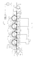
- the generally referenced 500 called imaging device is as an electrophotographic imaging device formed and in particular as a color imaging device, wherein color separation images in each of four color modules can be formed and aligned in the alignment of the toner image Elements are transferable to a receiving element, while that on a Paper transport path 516 overlying receiving element is moved by the device becomes.
- the paper transport path can be, for example, polyethylene terephthalate or a other plastic.
- a toner image bearing member can be a primary, imaging element or an intermediate transfer element, and a Toner image can be formed thereon or transferred from there to another element become.
- US 6,016,415 describes an example of a paper transport path.
- the device comprises four color modules, although the present invention also applies to two or more such modules is applicable.
- Each module (591B, 591C, 591M, 591Y) is constructed similarly, with the exception of the The fact that the paper transport path 516, which can also be designed as an endless belt, cooperates with all modules and that the receiving element through the Paper transport path 516 is transported from module to module.
- the elements in Fig. 10 which are the same from module to module have the same reference symbols, the suffix B, C, M and Y denote the color module to which the module is assigned, i.e. black, Cyan, magenta and yellow.
- each recording element is a color image of each module can record, and that in this example up to four color images of each Recording element can be included.
- the movement of the receiving element with the paper transport path 516 is such that each color image attached to the Transmission gap of each module is transferred to the receiving element, a Is transfer that is aligned with the previous color transfer, so the colors in a four-color image formed on the receiving element, one on top of the other are aligned on the receiving element.
- the receiving elements are then successively removed from the paper transport path and to a (not shown) Pass the fusing station to fix the dry toner images on the receiving element.
- the paper transport path is prepared for reuse by both surfaces with the help of corona loaders 522, 523 arranged opposite one another Charge can be applied, causing the charge on both surfaces of the Paper transport path is neutralized.
- Each color module from FIG. 10 comprises a primary, image-forming double-sleeve element, for example a rotating drum 503 B, C, M and Y.
- the drum rotates their respective axes in the directions indicated by the arrows.
- Each rotating Drum 503 B, C, M and Y comes with a removable, replaceable, compliant, inner sleeve element in the form of a tubular endless belt 507, e.g. 507 B by a removable, replaceable, outer, photoconductive Sleeve element in the form of a tubular endless belt, e.g. 509 B, narrow and not is adhered, whereupon a pigmented marking particle image or a row different colored marking particle images are formed.
- the inner Sleeve element 507 B comprises a (not shown in FIG.
- a preferred core element is rigid and in Generally not solid, but preferably comprises a hollow metal tube for example aluminum and can have internal structures, the chambers, Reinforcing struts, etc. may include.
- the core element preferably has one Out-of-roundness of less than 80 ⁇ m and ideally less than 20 ⁇ m.
- a primary loading agent for example a corona charger 505 B, C, M and Y, or a suitable one Loaders such as a shearer loader, brush loader, etc.
- the evenly charged surface is exposed by a suitable exposure means, for example with a laser 506 B, C, M and Y, or preferably an LED or other electro-optical Exposure device or even an optical exposure device to the charge on the surface of the primary imaging element to change and select one generate an electrostatic latent image corresponding to an image to be reproduced.
- a suitable exposure means for example with a laser 506 B, C, M and Y, or preferably an LED or other electro-optical Exposure device or even an optical exposure device to the charge on the surface of the primary imaging element to change and select one generate an electrostatic latent image corresponding to an image to be reproduced.
- the electrostatic latent image is created by applying pigmented marking particles by means of a development station 581 B, C, M and Y onto the latent image bearing Developed photoconductive drum.
- the development station includes one assigned, specific color of pigmented toner marking particles. Every module thus creates a series of different colored marking particle images on the corresponding photoconductor drum. Instead of the preferred photoconductor drum there is also a Photo conductor tape can be used.
- Each on a primary, imaging double-sleeve element or on one Marking particle image formed element carrying the toner image is electrostatically applied an outer surface of a corresponding secondary intermediate image transfer double sleeve member transfer, for example an intermediate transfer double-sleeve drum 508 B, C, M and Y.
- a suitable one Cleaning device 504 B, C, M and Y removed to re-surface Prepare the use and training of the following toner images.
- the Cleaning device may preferably include a cleaning brush, but may also be designed as a lamella or fabric web.
- Each intermediate transfer double-sleeve drum 508 has B, C, M and Y removable, replaceable, resilient inner sleeve element in the form of a tubular endless belt, which is designated, for example, with 541 B, and that closely and preferably not adhering to a removable, replaceable, compliant outer sleeve member is included, which is also in the form of a has tubular endless belt and e.g. is designated with 542 B.
- the outer sleeve member is stretched under tension to tight around the inner sleeve member to include.
- Inner sleeve member 541 is tight and preferably non-adherent a highly precise and essentially cylindrical core element (not in FIG. 10 shown).
- the inner sleeve member is stretched under tension to the To encompass core element closely.
- a preferred core element is rigid and generally not solid, but preferably comprises a hollow metal tube made of, for example Aluminum and can have internal structures, the chambers, reinforcing struts, etc. can include.
- the core element preferably has a runout of less than 80 ⁇ m and ideally less than 20 ⁇ m.
- Each inner sleeve member includes a reinforcement tape a resilient layer applied to the reinforcement tape and a protective layer, which is applied to the resilient layer or is close to it.
- a compliant inner sleeve layer is formed from an elastomer, such as one Polyurethane or other materials known in the published literature. The The primary function of an inner sleeve element is macro adjustment.
- a reinforcement band of an inner sleeve member can be rigid or flexible and has preferably an elastic modulus of less than 300 GPa.
- the reinforcement tape has preferably a thickness in the range of 1-500 microns and preferably in the range of 5 - 150 ⁇ m.
- a reinforcement tape can be made of any suitable material exist, including metal, elastomer, copolymer, plastic or others Materials, a fabric or a reinforced material such as a filler or Fibers, for example a reinforced silicone tape.
- a reinforcement tape can be on his Be provided with a high surface energy before the compliant Inner sleeve layer is formed thereon, and it can also have an inner surface with be provided with a low surface energy which is in contact with the core element located.
- a reinforcing band is a tubular endless band that for example, woven, extruded, electroformed, or from sheet metal using can be formed by, for example, ultrasonic welding or an adhesive.
- a reinforcement tape is preferably seamless. If a core element is electrical is biased to an electric field for the transfer of a toner image It may be necessary to provide the inner surface of the reinforcement tape (near the Core element) with a conductive material to coat the electrical contact with the central element to improve and at the same time a uniform, electrical Ensure potential at all points on the underside of the inner sleeve element.
- the compliant inner sleeve layer can be applied to the reinforcement tape by first stretching the reinforcement band on a mandrel.
- the compliant inner sleeve layer has a thickness in the range of 0.5-20 mm and best of 2 - 10 mm and a modulus of elasticity of preferably less than 10 MPa and am best in the range of 1 - 5 MPa.
- the compliant inner sleeve layer is on one Polymeric material, e.g. an elastomer, such as polyurethane or others in the published literature known materials.
- the compliant inner sleeve layer can comprise a material with one or more phases, e.g. a foam or one Dispersion of a solid phase in another.
- the compliant Inner sleeve layer a transverse elongation in the range of 0.2 - 0.5 and better in the range of 0.45 - 0.5, a preferred material being a polyurethane with a transverse expansion factor of approx. Is 0.495.
- the protective layer on the outside of an inner sleeve element is preferably made Made of a suitable material that is flexible and hard.
- the Protective layer a coating made of a synthetic material, preferably one Ceramer or a sol gel that is applied to the surface using a suitable coating process thick, compliant layer is applied.
- the protective layer can be a comprise thin metal tape, e.g. Nickel, with the compliant inner sleeve layer is glued, or has the shape of an endless belt that is under tension on the External surface of the resilient inner sleeve layer is applied, for example with Compressed air support or by cooling the reinforcement band and the compliant Inner sleeve layer to shrink it so that the endless metal band is pushed on can be.
- a protective layer of an inner sleeve member has a thickness of preferably 1 - 50 ⁇ m and best of 4 - 15 ⁇ m and a modulus of elasticity of preferably greater than 100 MPa and most preferably in the range of 0.5-20 GPa. It can be desirable that a stiffening layer serves as a protective layer, the Protective layer preferably has a modulus of elasticity greater than 0.1 GPa and am best of 50 - 300 GPa and a thickness of 10 - 200 ⁇ m.
- Sleeve member 542 B includes a stiffening layer, one on the stiffening layer applied, outer, flexible sleeve layer and one on the outer, flexible Separating layer applied to the sleeve layer (see e.g. Fig. 2).
- the outer sleeve element imparts the secondary intermediate image transfer double sleeve member Micro adjustment.
- the stiffening layer of the outer sleeve member preferably has the shape of a tubular endless belt, better the shape of a seamless belt.
- the main function of the stiffening layer is to maintain the hoop stress in the one below to minimize lying inner sleeve member 541 B, thereby the To reduce running deviations or to reduce them to a negligible level caused by the roller imbalance or by running deviations caused by Alignment tolerances in the engagement of the roller pairs of the primary, imaging Double sleeve element and the secondary intermediate image transfer double sleeve element caused.
- the stiffening layer also reduces Alignment errors by reducing or decreasing run deviations between the modules a negligible amount can be reduced.
- the Stiffening layer any suitable metal, e.g. Steel, nickel or another, highly wear-resistant metal.
- the stiffening layer can also be used without this being preferred will comprise an elastomer, for example a polyurethane, a polyimide, a polyamide or a fluoropolymer, wherein the elastomer has a yield strength that is during the Operation of the secondary intermediate image transfer double sleeve member is not is exceeded.
- the stiffening layer can also be a woven or reinforced one Material include or a sol-gel or a ceramer with a proof stress that during operation of the secondary intermediate image transfer double sleeve member is not is exceeded.
- the stiffening layer is made of nickel, e.g. in shape a suitable, thin, electroplated, seamless nickel band, that e.g.
- stiffening layer of the outer sleeve member 542 B, C, Y, M preferably a thickness of less than about 500 microns and better in the range of 10-200 ⁇ m.
- the stiffening layer preferably has a modulus of elasticity of more 0.1 GPa and best of 50 - 300 GPa.
- the outer resilient sleeve layer of the outer sleeve member 542 B, C, Y, M has volume resistivity and mechanical properties that are in the same range of use as those previously described for the resilient layers in the inner sleeve members of rollers 503 B and 508 B.
- the preferred thickness of the outer, resilient sleeve layer is in the range of 0.5-2.0 mm.
- the elastomer with the outer, flexible sleeve layer can be doped with a sufficiently conductive material (for example antistatic particles, ionically conductive materials or electrically conductive dopants).
- the outer, resilient sleeve layer should have a volume resistivity of preferably 10 7-10 11 ohm-cm, preferably about 10 9 ohm-cm.
- the outer, resilient sleeve layer can be applied to the stiffening layer by first pulling the stiffening layer onto a mandrel. The separating layer can then be applied to the outer, flexible sleeve layer.
- the separation layer of the outer sleeve member 542 B, C, Y, M preferably comprises a synthetic material such as a sol-gel, a ceramer, a polyurethane or a fluoropolymer, although other materials with good separation properties can also be used, including materials with low surface energy ,
- the separating layer has a modulus of elasticity of greater than 100 MPa, preferably 0.5-20 GPa and a thickness of preferably between 1-50 ⁇ m, more preferably 4-15 ⁇ m.
- the separating layer has a volume resistivity of preferably 10 7-10 13 Ohm-cm, most preferably about 10 10 Ohm-cm.
- Electrical bias is typically applied to the intermediate transfer double-sleeve drum 508 B to effect electrostatic transfer of a toner image from the primary double-sleeve imaging drum 503 B.
- the electrical bias is applied to the stiffening layer of the outer sleeve member 542 B by connection to an electrical voltage or current source, the stiffening layer preferably having a volume resistivity of less than about 10 10 ohm-cm and being most conductive , However, in some applications it is desirable to use a non-conductive stiffening layer.
- the stiffening layer can be coated with a thin, conductive material, for example a metal film, which is connected to an electrical voltage or current source.
- the electrical bias may be desirable to apply the electrical bias to the core member of the intermediate transfer double sleeve drum 508 B rather than to the stiffening layer of the inner sleeve member 541 B, that is, preferably to a metallic or conductive core or other conductive material with which the core is coated, for example a thin metal film, which is applied to the surface of a non-conductive core.
- the resilient inner sleeve layer and protective layer of inner sleeve member 541B should have suitable resistances, the resilient inner sleeve layer preferably having a volume resistance of 10 7-10 11 ohm-cm and best of about 10 9 ohm-cm and the protective layer has a volume resistance of less than about 10 10 ohm-cm.
- An outer sleeve element 509 B arranged on the primary imaging double sleeve drum 503 B comprises a stiffening layer and a photoconductive structure which is applied to the stiffening layer (see, for example, FIG. 3).
- the stiffening layer is preferably conductive.
- the photoconductive structure can comprise one or more layers, which can consist of any known, photoconductive material, for example an inorganic material or a dispersion, a homogeneous, organic, photoconductive layer, an aggregated, organic, photoconductive layer, a composite structure with a charge generating layer plus a charge transport layer, etc.
- the stiffening layer of the outer sleeve member 542 B is preferably grounded, in which case the stiffening layer preferably has a volume resistance of less than about 10 10 ohm-cm.
- the stiffening layer can be coated with a thin, conductive material, for example a metal film, which is connected to ground.
- a preferred outer sleeve member 509 B on the primary imaging double sleeve drum 503 B includes a stiffening layer, one on top of the Stiffening layer applied barrier layer, one applied on the barrier layer charge generating layer and one applied to the charge generating layer Charge transport layer (see e.g. Fig. 4 (a)).
- the stiffening layer of the outer Sleeve element 509 B preferably has the shape of a tubular endless belt.
- the stiffening layer of the outer sleeve element 509 B is a suitable one Substrate ready on which the charge generating layer and the Charge transport layer can be applied.
- the Stiffening layer thin and flexible and includes any suitable, conductive Material such as a metal e.g. Steel, nickel or another highly wear-resistant metal.
- the stiffening layer may comprise an elastomer, e.g.
- the Stiffening layer has a proof stress, which during the operation of the secondary Intermediate image transmission double sleeve element is not exceeded.
- the stiffening layer is made of nickel.
- a stiffening layer of the outer Sleeve element 509 B, C, Y, M preferably has a thickness of less than approximately 500 ⁇ m, preferably in the range of 10-200 ⁇ m.
- the stiffening layer has a Modulus of elasticity of more than approx. 0.1 GPa and best of 50 - 300 GPa.
- a preferred outer sleeve member 509 B includes a stiffening layer in the form a seamless nickel band made by electroforming, e.g. from Stork Screens America, Inc., Charlotte, North Carolina, USA.
- the one on the Stiffening layer applied photoconductive structure includes: one on the Stiffening layer applied polyamide resin barrier layer with a thickness of 0.5 - 1.0 ⁇ m; a charge-generating layer of the type described in US Pat. No.
- the charge-generating layer has a thickness of 0.5-1.0 ⁇ m and preferably of approximately 0.5 ⁇ m; and one on the charge-generating layer applied charge transport layer with a thickness of 12 - 35 ⁇ m and preferably 25 ⁇ m, the charge transport layer 2 Parts by weight of tri-tolylamine and 2 parts by weight of 1,1-bis ⁇ 4- (di-4-tolylamine) phenyl ⁇ methane in a binder of 1 part by weight of poly [4,4 '- (2-norbomylidene) bisphenol terephthalate-co-azelate- (60/40)] and 5 parts by weight of Makrolon TM polycarbonate, available from General Electric Company, Schenectady, NY, USA.
- the outer sleeve element 509 B micro-adjustment can be given by placing a thin, compliant layer on the Stiffening layer below the charge generating layer and the Charge transport layer is provided, the compliant layer having a thickness of preferably 0.5 - 2.0 mm.
- the preferred electrical and physical Properties are similar to those of the compliant layer of the outer sleeve member 542 B.
- the thin conductive layer can be in use be grounded.
- an optional thin, hard layer can be used as an outer Coating outside the charge transport layer can be provided to a higher To achieve wear resistance, for example from sol-gel, silicon carbide, diamond-like carbon, etc.
- the transmission of a monochrome marker particle image from the primary imaging double-sleeve roller achieve with a relatively small gap width (preferably from 2 - 15 mm and best of 3 - 8 mm) and a relatively moderate potential of e.g. 600 V or less of suitable polarity by connecting a (not shown) Voltage source preferably to the stiffening element of the outer sleeve element each secondary intermediate image transfer double sleeve member.
- each secondary intermediate image transfer double sleeve drum is formed on a toner image receiving surface Transferring element transferred into a gap between the Intermediate transfer roller and a transfer backup roller 521 B, C, M and Y is transported, which is provided with an outer barrier cloth and in a suitable manner is electrically biased by a power source 552 around the charged toner particle image electrostatically transferred to a receiving element.
- the admission student is out a suitable receiving element supply (not shown) and in a suitable manner Mounted on the paper transport path 516 and moves in succession in the Columns 510 B, C, M and Y where it matches the respective marker particle image in suitable, aligned relationship is applied to a compound Generate multicolor image.
- the colored pigments overlay to form areas of color different from the pigments.
- the Pick-up element emerges from the last gap and is by a (not shown) suitable transport mechanism transported to a fixer, where that Marking particle image on the receiving element by exposure to heat and / or pressure and is preferably fixed with both.
- a separator loader 524 can be provided to the receiving element with a neutralizing charge act to make it easier to separate from the paper transport path 516.
- the respective secondary intermediate image transfer double sleeve elements are by a corresponding cleaning device 511 B, C, M and Y for reuse cleaned.
- a preferred cleaning device is a brush cleaner, though too Slats or fabric cleaners can be used.
- sensors for example mechanical, electrical or optical sensors, are used in imaging device 500 to detect the To control the device with control signals. Such sensors are along the Travel of the receiving element between the receiving element magazine through the various nips arranged up to the fuser.
- Other sensors can be the Photoconductor drum of the primary imaging element, the Intermediate transfer member drum, the transfer support member and various Image processing stations can be assigned. The sensors determine the position of a Recording element on its path and the position of the photoconductor drum primary imaging element in relation to the imaging processing stations and generate corresponding control signals. These signals are fed as input information to a switching and control unit which is equipped with a microprocessor, for example.
- the switching and control unit Based on these signals and The switching and control unit generates a suitable program for the microprocessor LCU signals for timing the various electrographic Process stations to carry out the mapping process and to control the Drive of the various drums and belts via the motor M.
- the creation of a Program for a number of commercially available microprocessors that are used for Suitable for use with the invention is known in the art. The respective details of such a program depend on the architecture of the respective microprocessor.
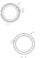
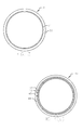
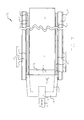
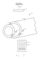
- FIG. 13 shows a sketch of an end region of an assembly 90 in a sectional view Representation of the inner and outer sleeve in a concentric arrangement on a double-sleeve roller according to the invention (without illustration of the core element).
- An inner one Sleeve member 91 is on the outer surface in a small section that is near the end of the inner sleeve member is identified, and an outer Sleeve member 92 is on the outer surface in a small section that is near the end of the outer sleeve element is provided with identifying marks.
- the outer sleeve element is slightly offset from its operative position in relation to
- the inner sleeve member is shown to have a location for an identification mark to make an outer portion of the inner sleeve member visible.
- the Identification marks are provided on the inner sleeve member to provide a parameter to be labeled in relation to the inner sleeve and they are also on the outer one Sleeve member provided to set a parameter related to the outer sleeve mark. Similar elements shown in Fig. 13 are of one or more Use quotation marks after the reference number.
- the identification marks on the inner sleeve element i.e. a set of descriptive tags that can be used in one small area 93 "on a cylindrical portion of the inner sleeve member one end of the inner sleeve member.
- the Identification marks on the inner sleeve element in a small area 93 ' one end of the sleeve 91 (the individual layers with the sleeve 91 are Not shown).
- the identifying marks on the outer sleeve member i.e. a set of descriptive marks are preferably in a small area 93 "" on one cylindrical portion of the outer sleeve member near one end of the outer Sleeve element arranged. Due to the relatively small thickness of the outer Sleeve element can have the identifying marks on the outer sleeve element in one small area 93 "'may be arranged on one end of the sleeve 92 (the individual Layers, including sleeve 92, are not shown).
- An enlarged view 93 one of the small areas 92 ', 92 ", 93'" or 92 “” shows that the descriptive Identification marks can be formed as bar codes, as by the reference symbol 94, which can be read, for example, by a scanner.
- the scanner can be in one electrophotographic machine can be arranged to a double-sleeve roller monitor, e.g. during machine operation or during idle time, or the scanner can be used externally during the installation or maintenance of an inventive device Roll are provided.
- the identifying marks can be identified by a Read, detect, or recognize identifier detector 95. As shown in Fig.
- the analog or digital output of the Identification mark detector passed to a switching and control unit in a electrostatographic machine using an inventive Intermediate transfer element roller is installed, or it can be processed externally, e.g. in a portable computer during installation or maintenance of a intermediate transfer element roller according to the invention, or it can be in another, suitable data processor can be processed.
- the identifying marks are optical, readable magnetically or by high frequency.
- the Identification marks include suitable markings, including Symbols or simple words, and they can be color coded.
- the identifying marks are also visually readable or interpretable. Suitable materials for the identification marks are, for example Inks, paints, magnetic materials, reflective materials, etc.
- the Identification marks can be arranged on a label affixed to the outer surface of the Sleeve element is attached.
- the identifying marks are also in sublime training or by punching with a stamp or by deforming a small, local area can be produced on the outer surface of the sleeve element.
- the Deformations can be detected mechanically or in another way or under Use of an identifier detector 95 in the form of a contact probe or by read other mechanical means. It may also be desirable for some applications be identification marks on the inner surface of a sleeve element or on the To arrange the outer surface of the central element.
- the outside diameter of a roll i.e. the Record the outer diameter of the outer sleeve member, so that the gap width or the alignment parameters can be adjusted accordingly.
- the resistance in radial Direction of an inner or outer sleeve element can be seen in the identifying marks record the optimal electrical bias on the roller To be able to coordinate performance.
- the effective hardness and the effective modulus of elasticity a sleeve of a roller according to the invention can be seen in the identifying marks record so that gap widths can be set in a suitable manner.
- the date of manufacture of both roller sleeves can be found in the identification marks for Diagnostic purposes record the end of life of a given sleeve estimate and be able to replace them in time.
- specific information for each given roller in relation to the Record runout e.g. as measured after manufacture, taking this Information can be used to optimize the alignment, e.g. between Modules.
- the alignment of a roller according to the invention for example an offset between a roller according to the invention and a primary imaging roller also describe by the identification marks.
- the alignment system can, for example use a software algorithm that measures the speed of the Controls line start clock signal that is applied to the LED write head. For each Color module, a separate line start clock signal is used, each of the length of the color toner image of the corresponding color separation image controls that of each module is generated, thereby ensuring that the color toner image is uniform and of is the correct length. It is well known that there is a change in the engagement between a primary imaging roller and an intermediate transfer roller Speed ratio changes, which changes the image length, e.g. by stretching or compression when the intervention is increased or decreased.
- Control line start clock signal is one of several parameters that are controlled must have an accurate alignment of each digitally written by the printhead Ensure image.
- the receiving elements used with the imaging device 500 can be different differ significantly from each other.
- it can be thin or trade thick paper, textured or embossed paper, or others textured or embossed materials as well as transparent materials, e.g. Plastic films.
- the different thickness and / or the different Volume resistance of the materials and the associated change in impedance has an effect on the electric field in columns 510 B, C, M and Y that serves to transfer the marking particles to the receiving elements.
- Also affects a change in relative humidity changes the conductivity of a Paper receiving element, which in turn affects the impedance and therefore also on the transmission field.
- the Paper transport path preferably has certain properties.
- the paper transport path 516 is preferably made of a material with a volume resistance greater than 10 5 ohm-cm; where the receiving element is not held electrostatically, a volume resistance between 10 8 ohm-cm and 10 11 ohm-cm is preferred. Where the receiving element is held electrostatically, a volume resistance of more than 1 x 10 12 ohm-cm is preferred for the paper transport path. This volume resistance is the resistance of at least one layer if the web is a multi-layer web.
- the sheet material can be made of any flexible material, such as fluorocopolymer (such as polyvinylidene fluoride), polycarbonate, polyurethane, polyethylene terephthalate, polyimide (such as Kapton TM), polyethylene naphthoate or silicone rubber. Whatever material is used, it can contain additives such as an antistatic (e.g. metal salts) or small conductive particles (e.g. carbon) to give the web the desired volume resistance. If materials with high volume resistance are used (ie larger than approx. 10 11 ohm-cm), additional corona chargers may be required to remove any residual charge remaining on the paper transport path after the receiving element has been removed.
- fluorocopolymer such as polyvinylidene fluoride
- polycarbonate such as polyurethane
- polyethylene terephthalate such as Kapton TM
- polyimide such as Kapton TM
- silicone rubber such as Kapton TM
- additives such as an antistatic (e.g. metal salt
- the paper transport path may have an additional conductive layer beneath the resistance layer that is electrically biased to cause the marking particles to transfer.
- an arrangement without a conductive layer is preferred in order to instead apply the pretension either through one or more support rollers or with a corona charger.
- the endless web is relatively thin (20 ⁇ m to 1000 ⁇ m, preferably 50 ⁇ m to 200 ⁇ m) and flexible.
- the invention also relates to an electrostatographic color machine in which a generally endless paper web receiver is used and a separate paper transport path is not required. Such continuous webs are typically unwound from a roll of paper which is supported to enable the paper to be unwound from the roll as the paper passes through the device as a continuous sheet.
- Receiving element can be charged by the loader 526 to the Pull the receiving element against the paper transport path 516 and "fix" it.
- a Doctor blade 527 assigned to the loader 526 can be provided around the receiving element to press on the paper transport path and, if necessary, between the receiving element and the Eliminate trapped air.
- a receiving element can be located in more than one image transmission gap at the same time, but preferably not simultaneously in the fuser gap and in the image transmission gap.
- the path of the recording element for the successive recording of the different color images is generally straight and enables the use of recording elements of different thicknesses.
- the endless paper transport path 516 is guided around a multiplicity of support elements.
- the plurality of support members are, for example, the rollers 513, 514, with the roller 513 preferably being driven by the motor M (of course, other support members, such as rails or bars, would also be used with the present invention).
- the paper transport path can be driven by the friction drive of the secondary intermediate image transfer double-sleeve rollers, whereby the primary, image-forming double-sleeve rollers are driven, or additional drives can be provided.
- the process speed is determined by the speed of the paper transport path, which can take any suitable speed, typically approx. 300 mm s -1 .
- the support structures 575 a, b, c, d and e are located directly upstream and downstream of each transfer nip in order to engage the web on the rear side and to change the straight course of the web such that the web is guided around each intermediate transfer element roller that on each side of the gap there is a contact area of more than 1 mm (gap pre-winding and gap post-winding) or at least on one side of the gap, the total contact area preferably being less than 20 mm.
- the gap is located where the pressure roller touches the back of the web or, if no pressure roller is used, where there is a substantial exposure to the electric field.
- the image transfer area of the gap forms a smaller area than the entire contact area.
- the contact area of the web around the secondary intermediate image transfer double-sleeve roller also provides a path in which the leading edge of the receiving element follows the curvature of the secondary intermediate image transfer double-sleeve roller, but separate from engagement with this roller while being along a substantially tangent to the surface of the cylindrical, secondary intermediate image transfer double-sleeve roller extending line. Pressurization by transfer support rollers 521B, C, M and Y occurs on the back of paper transport path 516 and brings the resilient secondary intermediate image transfer double sleeve member surface into close contact with the takeup member during transfer.
- each transfer support roller 521 B, C, M and Y on the paper transport path 516 is 7 pounds per square inch (0.04823 N / mm 2 ) or more.
- the transfer support rollers can be replaced by corona loaders, preloaded lamellae or preloaded brushes.
- Significant pressure is built up in the transfer nip to take advantage of the resilient intermediate transfer element which lies in the adaptation of the toned image to the receiving element and the image content from both a microscopic and macroscopic point of view.
- the pressure can be built up solely by the transfer pretensioner, or by additional pressure built up by another element, such as a roller, shoe, squeegee or brush.
- the contact area in front of the gap and the contact area behind the gap to any suitable value in any of the Module is adjustable, and can be different between modules by one Setting of the individual surveys of individual support structures is carried out, or by Arrange the support structures in places that are not halfway between the Modules, or by both of these measures.
- a larger number of support structures can be used, e.g. two support structures per module, one on each side of each transmission gap.
- Support structures can include rails, bars, rollers, etc.
- Fig. 11 which are similar to those shown in Fig. 10, are with a quotation mark (') after the reference symbol.
- the embodiment 11 is a toner color separation image in each of the four colors from each module 591 B ', 591 C ', 591 M' and 591 Y 'on the respective primary imaging Double sleeve elements formed, such as the photoconductive drums 503 B ', 503 C', 503 M 'and 503 Y', with each drum having a removable, replaceable interior Sleeve element and a removable, replaceable outer sleeve element comprises.
- the respective toner color separation images are aligned on one Transfer receiving element while the receiving element is moving or from Moves module to module and at each transmission gap (510 B 'is the only one designated gap) receives a corresponding toner color separation image.
- the exemplary embodiment from FIG. 11 are the secondary intermediate image transmission double-sleeve elements does not exist and each is transferred directly Image from the corresponding photoconductor double-sleeve drum on the Recording element, while the receiving element is successively through the Transfer stations moved while being held by the paper transport path 516 '.
- the outer Sleeve element 509 B In the preferred embodiment for the direct transfer of toner images from primary, imaging double-sleeve elements on recording sheets sees the outer Sleeve element 509 B 'pre-micro-adapts by taking charge generating Layer and the charge transport layer and on the stiffening layer a compliant Layer is applied, the resilient layer preferably having a thickness 0.5 - 2.0 mm.
- the preferred electrical and physical properties are similar to those of the compliant layer of the outer sleeve member 542 B.
- About the compliant layer may be a thin, conductive layer, e.g. made of nickel on which a barrier layer, a charge generating layer and a Charge transport layer is applied as previously described.
- the thin conductive Layer can be grounded during operation.
- the number is for the Full color imaging required modules by providing a photoconductive, outer sleeve member and a resilient secondary intermediate image transfer double sleeve member reduced.
- the elements shown in Fig. 12, which are similar to those in 10 and 11 are shown with a double quotation mark (") after the Provide reference numerals.
- one with the Reference number 600 designates two modules 691 BC and 691 MY, and also a different number of modules can be used.
- Each module is structured similarly, with except for the fact that the paper conveyor 516 ", which is also called an endless belt can be trained to work with all modules, and that the Receiving elements 512a “, 512b", 512c “and 512d" from the paper transport path 516 "from Can be transported module to module.
- module 691 BC includes one rotating, photoconductive, primary, imaging double sleeve drum 603 B, which in one counter-rotating, photoconductive, secondary intermediate image transfer double-sleeve drum 608 BC engages in a pressure gap designated 610 B, whereby the drum 608 BC in a pressure nip 610 BC engaged by the transfer backup roller 621 BC is located behind the paper transport path 516 ", and wherein the paper transport path is the Drum 608 BC drives by friction, which in turn drives drum 603 B.
- a motor drive can alternatively be used to the Drum to complement a drum.
- the movement of the paper transport path 516 " is complete indicated by an arrow and is done by driving the roller 513 ".
- the primary, double sleeve imaging roller 603 B includes a rigid one (not shown in Fig. 12) Core element, a removable, replaceable, resilient, inner sleeve element 607 B, which preferably grips and surrounds the core element in a non-adhesive manner, and a removable, replaceable, photoconductive, outer sleeve element 609 B, which the inner sleeve member preferably grips and surrounds non-stick.
- the photoconductive, primary double-sleeve imaging drum 603 BC includes (not shown in FIG.
- each drum 603 B, 608 BC, 603 M and 608 MY becomes a different, single color Toner image formed, for example from black, cyan, magenta and yellow toners as indicated by the letters B, C, M and Y, or from other colors or from a different number of colors. They are also toner free Color attributes can be used.
- a black toner image is printed on the Drum 603 B formed using the primary loader 605 B, the Lasers 606 B and the development station 681 B.
- a cyan Toner image on drum 608 BC using primary charger 605 C, the Lasers 606 C and the development station 681 C.
- the black toner image becomes electrostatic in the gap 610 B from drum 603 B to drum 608 BC transferred so that the black toner image is applied to the cyan image, creating a first, aligned, composite image.
- the rotary motion the drum 608 BC brings the first composite image into the gap 610 BC, where the first composite image is electrostatically transferred to a recording sheet, for example on paper sheet 512b ".
- a magenta-colored toner image on the primary, image-forming double-sleeve element 603 B, and a yellow-colored toner image, which is on the photoconductive, secondary intermediate image transfer double sleeve member 608 MY is formed in combined in the same way in gap 610 M to form a second, composite image that is transmitted in column 610 MY over the first composite image to align an aligned four-color composite image on the recording sheet produce.
- the Transfer backup rollers 521, 521 'and 621 BC have a preferred diameter of 20-80 mm and preferably run in continuous current mode.
- the diameters of the primary, imaging double sleeve elements and the secondary intermediate image transfer double sleeve elements are preferably in the range of 80-240 mm.
- the three Embodiments of FIGS. 10, 11 and 12 can have different recording sheets located in different columns at the same time; so it is possible that one Recording sheet is located in two adjacent columns at the same time, the time of Image generation and the corresponding transfer to the recording sheet selected in this way is that the images are transferred correctly, so that the corresponding Images are aligned and expected to be transferred.
- Each of the three exemplary embodiments of FIGS. 10, 11 and 12 has one Paper transport path provided to transport a sheet through gaps, in which toner images have been transferred to the recording sheet, as previously described has been.
- an intermediate transfer member can be in the form a web can be used, with a primary imaging double sleeve member is used in the color reproduction device described here.
- a primary, imaging element in the form of a web with a secondary Intermediate image transmission double sleeve element can be used.
- the device is also can be used to color images in different color combinations instead of to use the four-color image described. It is possible to have fewer color modules in the To provide device or additional color modules in the device. Although it affects present description the formation of a composite image on a Recording sheet, which is composed of a plurality of color images, but the Invention takes into account images from different physical toners can be combined on a recording sheet to form a resultant composite Train picture. So with the help of the transmission device described here and the described method, a black toner image can be transferred to a recording sheet, wherein the toner image is formed from non-magnetic toner, and wherein a second, black image on the same recording sheet with a magnetic toner is trained.
- the contact area of the web which supports the receiving element in contact with the element carrying the toner image is determined by the tension of the conveyor belt.
- the actual transfer gap in which the main part of the electric field is present between the element carrying the toner image and the transfer support roller or another counterelectrode for transferring the toner image to the receiving element is smaller than this contact area.
- Providing a contact area that is longer than the actual transfer gap reduces the risk of pre-gap transfer and pre-portioning, especially if the conveyor belt is insulating.
- the contact area, at least in the pre-nip area should preferably be larger than the roll nip by more than 1 mm.
- the pressure roller should preferably have a medium conductivity, ie a volume resistance of 10 7-10 11 ohm-cm; however, transfer support rollers with high conductivity can also be used, ie with the conductivity of a metal.
- Other structures can also be used in place of the transfer support rollers to pressurize the web at the nip, including elements with conductive fibers that are electrically biased and provided with a stiffening structure on either side of the brush to apply pressure to exercise the web, or rollers with conductive fibers.
- the transmission of the Toner image on the secondary intermediate image transfer double sleeve member and of the secondary intermediate image transfer double sleeve member on the Pickup element, and generally all toner image transfers occur electrostatically and preferably without exposure to heat, resulting in a Melt the toner.
- the primary imaging element can use images Form photoconductive elements, as already described, or using dielectric elements and with electrographic recording.
- the toners used are preferably dry toners, which are preferably non-magnetic are; the development stations are as two-component development stations known.
- One-component developers can also be used, but not too prefer is.
- Liquid toners can also be used, but are also not preferred.
- wiper blades 560 and 562 (Fig. 10), 560 ', 562' (Fig. 11) or 560 ", 562" (Fig. 12). Wiper blades are preferred for cleaning the front and back used.
- Additional thin layers (not shown in any of the figures) to support adhesion between the layers are in the manufacture of inner and outer sleeve elements usable, such as the well-known top or substrate layers.
- a surface area can be created with a thickness in the range of a few molecular dimensions in a chemical manner be selected or modified that the area with chemical molecular groups low surface energy on these surfaces (not shown in any of the figures) having.
- the invention describes a double sleeve roll for use in a electrostatographic machine, the double-sleeve roller one essentially includes a cylindrical and rigid core element, an exchangeable, removable, multilayer, inner sleeve element in the form of a tubular endless belt with at least one resilient layer such that the inner sleeve member Core element surrounds and is tight and non-adherent, and a interchangeable, removable, multilayer, outer sleeve element in the form of a tubular endless belt with at least one synthetic layer such that the outer sleeve member surrounds the inner sleeve member and tight on this and not adheres to.
- the synthetic layer can be, for example, a plastic, a polymer Copolymer, an elastomer, a foam, a photoconductive material, a material with Filling particles, a material with two or more phases or a fiber-reinforced one Material.
- the inner sleeve member is using a sleeve installation process can be applied to the core element, and the outer sleeve element is by means of a Sleeve installation method applicable to the inner sleeve member, the outer Sleeve member from the inner sleeve member by a sleeve removal process is removable, and wherein the inner sleeve member from the core member through a Sleeve removal process is removable, and wherein all sleeve elements are in the form of a Continuous web not only maintained during operation of the double-sleeve roller, but also also during the installation of a sleeve element or during the removal of one The sleeve member.
- the double-sleeve roller can a primary, imaging double sleeve element, a secondary Intermediate image transfer double sleeve element or a bifunctional, photoconductive secondary intermediate image transfer double sleeve element.
- a preferred sleeve installation method involves providing a source compressed fluids on the underside of a sleeve member, the preferred compressed fluid is compressed air; turning on the source of compressed fluids elastic expansion of the sleeve element, so that the sleeve element along the Surface of a substrate, which comprises a further element, is displaceable by the to surround another element, the other element being a core element or one on top of the Core element arranged inner sleeve member can be; further exposure to the source of compressed fluid while the sleeve member to be displaced continues is postponed until it has reached a predetermined position around the other element; the Turning off the source of the compressed fluid, causing the sleeve member can relax and grasp the other element under tension.
- Sleeve installation procedure can be used, e.g. Heating the on the substrate installing sleeve member or cooling the substrate to by heating or To be able to use cooling changes caused temporarily.
- a preferred sleeve end installation method involves providing a source compressed fluids on the underside of a sleeve member, the preferred compressed fluid is compressed air; turning on the source of compressed fluids elastic expansion of the sleeve element, so that the sleeve element along the Surface of a substrate comprising another element can be moved to the to surround another element, the other element being a core element or one on top of the Core element is arranged inner sleeve element; further exposure to the Source of compressed fluid while the sleeve member is moved further from and other item is removed; Turn off the source of the compressed fluid.
- Other sleeve installation methods can be used, including Heating the on the substrate sleeve element to be uninstalled or the substrate cooled by heating or cooling can cause temporary changes in dimensions.
- FIG. 1 shows a sectional view of a preferred Embodiment 10 of an inner sleeve member 15 which on a cylindrical, rigid core element 11 is arranged.
- the inner sleeve member 15 has preferably in the form of a tubular endless belt and can be in one Double-sleeve rollers are used which have a resilient or photoconductive outer Includes sleeve element.
- the preferred core element 11 is essentially rigid and Generally not solid throughout, as shown in FIG. 1, and preferably includes a hollow, cylindrical metal tube or a sleeve made of, for example, aluminum.
- the core element 11 has a smooth surface and preferably a non-roundness of less than 80 ⁇ m and ideally less than 20 ⁇ m.
- the core element 11 can be a Have internal structure which may include chambers e.g. for compressed air and related Pipes, reinforcing struts, etc., and can be provided with holes for compressed air from an inner chamber through the cylindrical tube during installation and the Uninstall the inner sleeve member 15 to guide.
- Chambers e.g. for compressed air and related Pipes, reinforcing struts, etc.
- the inner sleeve member 15 includes a reinforcing band 12, an inner, resilient one Layer 13, which is arranged on the reinforcing tape 12 and one on the inner, flexible layer arranged protective layer 14.
- the reinforcing tape 12 can be rigid or be flexible has a modulus of elasticity of preferably less than 300 GPa and a thickness of preferably 1-500 ⁇ m and most preferably 5-150 ⁇ m.
- On Reinforcement tape can be made of any suitable material, including Metal, elastomer, copolymer, plastic or other materials, a fabric or a reinforced material, such as a filler or fibers, for example a reinforced one Silicone band.
- a reinforcement tape can have a high surface energy on its outer surface have before the compliant inner sleeve layer is formed thereon, and it can also on its inner surface which is in contact with the core element have low surface energy.
- a reinforcing tape is preferably a Endless belt or a tubular belt that, for example, is woven, extruded, electroformed or from sheet metal using, for example Ultrasonic welding or an adhesive can be generated. Preferably that is Reinforcement tape seamless.
- the resilient inner sleeve layer 13 preferably has a thickness in the range of 0.5 - 20 mm and best of 2 - 10 mm and a modulus of elasticity of preferably less than 10 MPa and best in the range of 1 - 5 MPa.
- the compliant Inner sleeve layer 13 is formed from a polymer material, e.g. an elastomer, such as polyurethane or other materials known in the published literature.
- the compliant inner sleeve layer 13 may be a material with one or more phases include, e.g. a foam or a solid phase dispersion in another.
- the resilient inner sleeve layer preferably has a transverse expansion factor in the range of 0.2-0.5 and better in the range of 0.45-0.5, being a preferred material Polyurethane with a transverse expansion factor of approximately 0.495.
- the protective layer 14 is preferably made of a suitable material is flexible and hard, e.g. a synthetic material, preferably a Ceramer or a sol gel that is applied to the thick layer using a suitable coating process compliant inner sleeve layer 13 is applied.
- the Protective layer 14 comprise a thin metal tape, e.g. Nickel that with the compliant Inner sleeve layer 13 is glued, or which has the shape of an endless belt, the applied under tension to the outer surface of the resilient inner sleeve layer 13 is, for example with compressed air support or by cooling the Reinforcement tape and the resilient inner sleeve layer to shrink it so that the endless metal band can be pushed on.
- the protective layer 14 has one Thickness of preferably 1-50 ⁇ m and most preferably 4-15 ⁇ m as well as a Young's modulus, preferably greater than 100 MPa and best in the range of 0.5-20 GPa.
- Fig. 2 shows a sectional view of a preferred embodiment of a resilient outer sleeve member 20 which can be used in a secondary intermediate image transfer double sleeve member.
- the resilient outer sleeve member 20 is preferably a tubular endless belt and comprises a stiffening layer 21, an outer, resilient sleeve layer 22 applied to the stiffening layer, and a separating layer 23 applied to the thin outer, resilient sleeve layer 23.
- the stiffening layer 21 is preferably in the form of a seamless continuous web and preferably comprises a suitable metal, for example steel, nickel or another highly wear-resistant metal.
- the stiffening layer 21 can comprise an elastomer, for example a polyurethane, a polyimide, a polyamide or a fluoropolymer, the elastomer having an elastic limit which is not exceeded during operation.
- the stiffening layer 21 can also comprise a fabric or a reinforced material or a sol-gel or a ceramer with a proof stress that is not exceeded during operation.
- the stiffening layer 21 preferably consists of nickel, for example in the form of a suitable, thin, electroformed, seamless nickel band, which can be obtained, for example, from Stork Screens America, Inc., Charlotte, North Carolina, USA.
- a stiffening layer 21 is preferably less than 500 microns thick, and most preferably in the range of 10-200 microns.
- the stiffening layer 21 has a modulus of elasticity of preferably more than approximately 0.1 GPa and most preferably 50-300 GPa.
- the stiffening layer 21 preferably has a volume resistivity of less than approximately 10 10 ohm-cm and is preferably connectable to an electrical current or voltage source. In some applications, however, it is desirable to use a non-conductive material for the stiffening layer 21. In this case, the stiffening layer 21 can be coated with a thin, conductive material, for example a metal film, which is connected to an electrical voltage or current source.
- the outer resilient sleeve layer 22 has a thickness in the range of 0.5-2 mm and an elastic modulus of preferably less than 10 MPa and most preferably in the range 1-5 MPa.
- the outer compliant sleeve layer 22 is preferably formed from a polymeric material, such as an elastomer such as polyurethane or other materials known in the published literature, and may comprise a material with one or more phases, such as a foam or a solid phase dispersion in one others.
- the outer, resilient sleeve layer 22 has a transverse elongation number in the range of 0.2-0.5 and better in the range of 0.45-0.5, a preferred material being a polyurethane with a transverse elongation number of approximately 0.495.
- the elastomer from which the outer, flexible sleeve layer 22 is made can be doped with a sufficiently conductive material (for example antistatic particles, ionically conductive materials or electrically conductive dopants).
- the outer, resilient sleeve layer 22 should preferably have a volume resistance of 10 7-10 11 ohm-cm and most preferably about 10 9 ohm-cm.
- the separating layer 23 preferably comprises a synthetic material, such as a sol-gel, a ceramer, a polyurethane or a fluoropolymer, although other materials with good separating properties can also be used, including materials with low surface energy.
- the separating layer 23 has a modulus of elasticity of greater than 100 MPa, preferably 0.5-20 GPa and a thickness of preferably 1-50 ⁇ m, more preferably 4-15 ⁇ m.
- the separating layer 23 has a volume resistivity of preferably 10 7-10 13 Ohm-cm, most preferably about 10 10 Ohm-cm.
- FIG. 3 shows a photoconductive outer sleeve member 30 suitable for a primary, double sleeve, imaging drum.
- the photoconductive outer sleeve member 30 is preferably an endless tubular belt and includes a stiffening layer 31 and a photoconductive structure 32 applied to the stiffening layer.
- the photoconductive structure 32 may include one or more layers made of any known and suitable photoconductive material may consist of, for example, an inorganic material or a dispersion, a homogeneous, organic, photoconductive layer, an aggregated, organic, photoconductive layer, a composite structure with a charge generating layer plus a charge transport layer, etc.
- the stiffening layer 31 is preferably conductive with a volume resistivity of less as approx.
- the stiffening layer 31 can be coated with a thin, conductive material, for example a metal film, which can be connected to ground.
- a stiffening layer 31 may comprise any suitable, strong, flexible material and is preferably less than 500 microns thick, and most preferably in the range 10-200 microns.
- the stiffening layer has a modulus of elasticity of preferably more than about 0.1 GPa and most preferably 50-300 GPa.
- the stiffening layer is preferably in the form of a seamless, tubular band.
- Fig. 4 (a) shows a preferred embodiment of a photoconductive outer Sleeve member 40A, which is a stiffening layer 41, one on the stiffening layer applied barrier layer 42, a charge-generating layer applied to the barrier layer Layer 43 and one deposited on the charge generating layer Charge transport layer 44 includes.
- the outer sleeve member 40A is preferably a tubular endless belt.
- a stiffening layer 41 is preferably in the form a seamless, tubular band and can be any suitable, strong, pliable Include material.
- the stiffening layer 41 has a thickness of less than 500 ⁇ m and preferably from 10 to 200 ⁇ m and an elastic modulus of greater than 0.1 GPa, preferably from 50-300 GPa.
- the stiffening layer 41 preferably consists of a seamless nickel band of approx. 127 ⁇ m made by electroforming (0.005 inch) thickness, e.g. by Stork Screens America, Inc., Charlotte, North Carolina, USA, can be obtained.
- the barrier layer 42 comprises any suitable material for example, a nylon that charges injection from the stiffening layer 41 prevented, and the barrier layer preferably comprises a polyamide resin layer of 0.5 - 1.0 ⁇ m thickness, which is applied to the stiffening layer 41.
- the Charge generating layer 43 may comprise any suitable material, including in the literature well-known dispersions.
- the charge generating layer 43 is one Layer of the type described in US Pat. No.
- the charge-generating layer has a thickness of 0.5 - 1.0 ⁇ m and preferably of about 0.5 ⁇ m.
- Those on the charge-generating Layer 43 applied charge transport layer 44 has a thickness of 12-35 microns and preferably of about 25 microns.
- the charge transport layer 44 can be any suitable Compositions and materials include those published in the literature are generally known, the charge transport layer preferably 2 parts by weight Tri-tolylamine and 2 parts by weight of 1,1-bis ⁇ 4- (di-4-tolylamine) phenyl ⁇ methane in one Binder of 1 part by weight of poly [4,4 '- (2-norbomylidene) bisphenol terephthalate-Co-Azelate- (60/40)] and 5 parts by weight of Makrolon TM polycarbonate, available from General Electric Company, Schenectady, NY, USA, as in US 5,614,342 described.
- Fig. 4 (b) shows a preferred embodiment of a photoconductive outer Sleeve member, as represented by a multi-layer composite structure 40B, which in the Compared to the outer sleeve member 40A of Figure 4 (a) includes additional layers. With the exception of the additional layers, some layers correspond to this more preferred embodiment directly the layers 41, 42, 43 and 44 of the outer Sleeve element 40A, the properties and dimensions of which correspond to the layers, which are labeled 41 ', 42', 43 'and 44' in Fig. 4 (B).
- the outer sleeve member 40B comprises a stiffening layer 41 ', which is preferably in the form of a seamless, has tubular endless belt, a formed on the stiffening layer, compliant layer 45, an optional electrode layer applied to layer 45 46, an optional barrier layer 42 ′ applied on the electrode layer 46, one on the Barrier layer applied, charge generating layer 43 'and one on the charge transport layer 44 'applied to the charge generating layer.
- the optional Barrier layer 42 ' may require unwanted charge injections suppress that either from the compliant layer 45 to the charge generating Act layer or from the optional electrode layer 46 on the charge generating Layer.
- the outer sleeve member 40B is preferably a seamless endless belt.
- the optional electrode layer 46 comprises any thin, conductive and flexible material, such as nickel, and is with mass connected. Aside from a certain volume resistance that is required the resilient layer 45 is equal to that in terms of properties and dimensions Layer 22 of the resilient outer sleeve member 20 of FIG. 2.
- An advantage of the outer sleeve member 40B opposite outer sleeve member 40A consists of micro-adjustment created by the compliant layer 45.
- the flexible layer 45 has a volume resistance of preferably less than approximately 10 10 ohm-cm and no electrode layer 46, as a result of which the stiffening layer 41 ′ can be connected to ground and has a volume resistance similar to the stiffening layer 41 must, or if the stiffening layer 41 'has an insulating effect, it must be coated with a thin, flexible and conductive layer which can be connected to ground.
- 5-9 show preferred devices and methods for installing Sleeve elements on a double sleeve roller and for removing sleeve elements from a double sleeve roller.
- Fig. 5 shows a sectional view of a preferred embodiment of a Double sleeve roller, the associated outer sleeve element on an inner Sleeve element installed or removed.
- the double sleeve roller is axially supported at both ends.
- the holder is moved at one end, and the double-sleeve roller is located at one end (not shown) that is opposite to that at which a sleeve element is installed or removed, held and remains with one Frame element of an electrostatographic machine during installation or Uninstall a sleeve connected.
- Fig. 5 in Generally any double sleeve roller according to the invention can represent.
- the double-sleeve roller is used as a primary, imaging Double sleeve roller 50 shown.
- Some of the numbered sleeve components Fig. 5 correspond to those described above and are by the corresponding Reference symbols denoted by single quotes.
- An inner sleeve member 15 ' is in Installed position shown in part of the core member 59.
- the inner sleeve member 15 ' comprises a reinforcement tape 12 'in close, non-adhesive contact with the Core element 59, a resilient one arranged on the reinforcement band 12 ' Inner sleeve layer 13 'and one arranged on the resilient inner sleeve layer 13' hard protective layer 14 '.
- An outer sleeve member 30 ' is during the process of Installation or uninstallation of the inner sleeve member 15 'shown.
- the outer sleeve member 30 ' includes a stiffening layer 31' and a photoconductive structure 32 'applied to the stiffening layer 31'.
- the Installation or uninstallation of an outer sleeve member 30 'is by the Flow of a pressurized fluid through the opening 57a of the core enables, for example, from a source of compressed fluid that is is preferably compressed air from a line 57b, then through a Connection channel 57, which leads through an end block 51 and connects to a line 58 within an end cap 52 which abuts the end block 51.
- the Line 58 is one of a plurality of identical lines that differ from a common one Extend distributor 53 from a beam. All of these lines (of which the others not shown) come to the surface of the end cap 52 to form compressed air corresponding variety of openings to guide the completion of the variety of Form lines on the periphery of the end cap 52. Those from the multitude of Compressed air emerging from openings below the outer sleeve element 30 'causes this elastic expansion, whereby the outer sleeve member 30 'on the surface of the inner sleeve member 15 'is slidable.
- the end cap 52 includes one annular, conical section 52a to push the outer Sleeve element 30 'to facilitate at the beginning.
- the end cap 52 also includes one annular chamfer 56, which the pushing and pulling of the outer sleeve member 30 'relieved.
- the following description assumes that the outer Sleeve element 30 'has been removed. Once the outer sleeve member 30 is removed has become, the source of the compressed air passing through the connecting duct 57 off. To remove the inner sleeve member 15 ', the End cap 52 removed. Then, as shown in Fig. 5, compressed air is passed through another Line 54a, which opens into a distributor 54 within the end block 51, which in turn leads to a multitude of lines running radially through the end of the Kemelements 59 occur and in a corresponding plurality of openings on the Periphery of the core member 59 end.
- the inner sleeve member 15 ' is stretched, whereby it from the Core element 59 can be removed; after removal of the inner sleeve element 15 ' the compressed air source is switched off.
- the steps of the previously described Reverse procedure To replace a bare core element 59, the steps of the previously described Reverse procedure.
- the inner sleeve member 15 ' has a annular chamfer 56 at the end of the core element has been found to be helpful.
- Double-sleeve roller which is generally any double-sleeve roller according to the invention represents.
- the double sleeve roll is considered a secondary Intermediate image transmission double sleeve element 60 shown, but it can also be a primary, imaging double sleeve element.
- Some of the numbered 6 correspond to the previously described and are by the corresponding reference numerals with quotation marks.
- the secondary Intermediate image transfer double sleeve member 60 includes a core member 61 (of which no internal details are shown), an inner sleeve element 15 'in a narrow, not adhesive contact with the core member 61 and a resilient outer sleeve member 20 'in close, non-adhesive contact with the inner sleeve member 15'.
- the resilient outer sleeve member 20 ' includes one Stiffening layer 21 ', a compliant layer 22' and a release layer 23 ', wherein it should be noted that the resilient outer sleeve member 20 'also photoconductive outer sleeve element of a primary, imaging Can represent double sleeve element.
- two bevels, replaceable end pieces shown namely an end piece 62 with a larger diameter at one end of the roller 60 and an end piece 63 with a smaller diameter at the other end of the roller.
- the axis elements 68 and 69 are on the frame elements of an electrostatographic Machine supported, wherein during the operation of the roller 60 each axis element in stores its corresponding opening and thus holds the roller. As with the Shown with double arrows in each of the axis elements, each axis element is independent can be inserted into and removed from the corresponding opening as required, when a sleeve is installed or uninstalled.
- the secondary Intermediate image transfer double sleeve roller 60 is at one or the other end constantly held during removal or replacement of a sleeve.
- the Axle member 68 is removed from opening 66 when outer sleeve member 20 ' to be uninstalled or replaced, the axis element 69 in the Opening 67 remains as a holder.
- the axis element 69 from the Opening 67 is removed when the inner sleeve member 15 'is uninstalled or replaced should be, the axis member 68 remains in the opening 67 as a holder.
- the Axle elements 68 and 69 and the openings 66 and 67 are only exemplary here shown; Suitable means can therefore be provided to attach the roller to each Hold end separately.
- the plurality of openings is connected to a source of compressed air which serves to compliant, outer sleeve member 20 'during installation or removal to stretch from the inner sleeve member 15 '.
- the inner layer is superimposed in the same way Sleeve member 15 'a plurality of openings through a cylindrical Section of the end piece 63 are introduced, the cylindrical portion one Has outer diameter which is substantially equal to the outer diameter of the Core element 61.
- the large number of openings is connected to a compressed air source, which serves the inner sleeve member 15 'during installation on or Uninstall from the core member 61 to stretch, the resilient, outer Sleeve member 20 'during installation or removal of the interior Sleeve element 15 'is not present.
- Double-sleeve roller which is generally any double-sleeve roller according to the invention represents.
- the double sleeve roll is considered a secondary Intermediate image transmission double sleeve element 70 shown, but it can also be a primary, imaging double sleeve element.
- Some of the numbered 7 correspond to those described above and are by the corresponding reference numerals with double quotes.
- the secondary Intermediate image transfer double sleeve member 70 includes a core member 71 (of which no internal details are shown), an inner sleeve element 15 "in narrow, not adhesive contact with the core member 71 and a resilient outer Sleeve member 20 'in close non-adhesive contact with the inner sleeve member 15 ". Furthermore, a disk-shaped end element 72 is shown, which is permanently attached to one End of the core member 71 is fixed, wherein the disc-shaped end member 72 in Has essentially the same outer diameter as the core element 71.
- the inner sleeve member 15 “includes a reinforcement tape 12" in a tight, non-adherent manner Contact with the core element 71, a on the reinforcing tape 12 ", flexible inner sleeve layer 13 “and one on the flexible inner sleeve layer 13" arranged hard protective layer 14 ".
- the resilient outer sleeve member 20" comprises a stiffening layer 21 ", a compliant layer 22" and a separating layer 23 ", it should be noted that the resilient outer sleeve member 20 "also a photoconductive, outer sleeve element of a primary, imaging Can represent double sleeve element.
- a removable, conical end piece 74 is shown, which with a Opening 79 is provided, into which an axis element 78 can be introduced.
- the axis element 78 is supported on a frame member of an electrostatographic machine, wherein it during operation of the secondary intermediate image transfer double sleeve member 70 in its corresponding opening 79 and thus the roller in connection with a permanently held at the other end of the roller (not shown).
- the secondary intermediate image transfer double sleeve member 70 is permanent by this Axle constantly held during removal or replacement of a sleeve. How shown with the double arrow, the axis member 78 from the opening 79th removed when one of the sleeves is installed or uninstalled.
- the outer sleeve member 20 "overlies a plurality of openings through a cylindrical portion of the tapered end piece 72 is inserted, wherein the cylindrical portion has an outer diameter that is substantially the same the sum of the outer diameter of the core member 71 plus the thickness of the inner one Sleeve member is 15 ".
- the plurality of openings are with a compressed air source connected, which serves the resilient outer sleeve member 20 "during the Installation on or deinstallation of the inner sleeve element 15 ".
- the inner sleeve member 15 "overlies a plurality of openings that step through a disc-shaped end element.
- the variety of openings is one Connected compressed air source, which serves to the inner sleeve member 15 "during the Stretch installation on or deinstallation of the core element 71, which inner sleeve element 15 "is pushed over the temporary element 73.
- FIG. 8 schematically shows how the outer and inner sleeve member of the one in FIG. 6 secondary intermediate image transfer double sleeve roller 60 shown.
- axle member 68 is removed from the tapered end piece 62; in (b) the resilient outer sleeve member 20 'with compressed air support as before described, peeled and removed from the inner sleeve member 15 '; in (c) it becomes Axis element 68 inserted again and the axis element 69 removed; in (d) it becomes inner sleeve element 15 'with compressed air support is withdrawn from the core element 61 and removed.
- Fig. 9 shows a schematic representation of how the inner and outer sleeve member the secondary intermediate image transfer double sleeve member 70 shown in FIG. 7 be removed.
- the axis member 78 becomes from the tapered end piece 74 away; in (b) the resilient outer sleeve member 20 "with Compressed air support, as previously described, from the inner sleeve member 15 " peeled and removed, whereupon the conical end piece 74 is removed; in (c) the conical element 73 with a smaller diameter on the disc-shaped End member 72 attached; in (d) the inner sleeve member 15 "with Compressed air support is removed from core member 71 and removed.
- steps (1), (2) and (3) processes for producing a secondary intermediate image transfer double-sleeve roller according to the invention described. These methods are also used to manufacture an internal one according to the invention Sleeve element suitable for a primary, image-forming double-sleeve roller.
- the adhesion between a reinforcing tape and a flexible inner sleeve layer is indispensable for the production of an inner sleeve element, which one Hard grinding process includes.
- Good liability ensures that an inner Sleeve element can be finish-ground with tools according to the prior art, to achieve very little runout.
- Better liability of a compliant Inner sleeve layer for example the adhesion of a polyurethane to one Reinforcement tape from e.g. Nickel, can be achieved by using the Nickel surface is cleaned well, e.g. by degreasing the nickel surface with a Ketone solvent or by etching with a dilute strong acid or alkali. Also roughening the surface can promote better adhesion.
- the reinforcement tape Tape e.g. a copper-coated one made by electro-forming Nickel tape, e.g. by Stork Screens America, Inc., of Charlotte, NC, USA.
- copper metals such as aluminum or zinc can also be used to Coating the nickel surface to improve adhesion.
- Adhesion promoters are CONAP® AD6, CONAP® AD1147 from Conap Inc.
- adhesion promoters are less desirable because an additional layer (the adhesion promoter layer) between the nickel and the conductive polyurethane contaminate the inner sleeve member and whose resistance could change.
- the preferred method is to Surface of a nickel sleeve, as explained in the example below.
- the shelf life of the remuneration solution is one Hour. Immerse the cleaned nickel strip in a tempering solution for 10 minutes. Nickel band with Rinse off ethanol. Cure the reinforcement tape at 150 ° C for 30 minutes.
- a polyurethane cloth is cast on a reinforcing tape in a mold commercially available prepolymers, polyols, chain extenders and antistatic agents educated.
- the reinforcement tape is on a cylindrical metal mandrel stretched to form the inner wall of the mold; the thorn is at the center of one arranged cylindrical outer wall, the gap between the thickness of the cloth.
- US 4,729,925 and 5,212,032 describe the manufacture of Resistance polyurethane elastomers based on Di [oxydiethylenebis (polycaprolactone) yl] 5-sulfo-1,3-benzenedicarboxylat.
- 0.364 DGFC antistatic agent 52.83 g of PPG2000, one with dihydric alcohol terminated prepolymer from Dow Chemical Company of Midland, MI, USA, and 3 Drop of SAG 47 foam inhibitor from Witco Corporation of Greenwich, CT, USA, Mix. 52.83 preheated L42, a prepolymer terminated with diisocyanate from Uniroyal Chemical Company of Middlebury, CT, USA and 11.19 EC300 diamine from Add Albemarle Corporation of Baton Rouge, LA, USA (without heating). So far required three drops of dibutyltin dilaurate (from Aldrich Chemical Company Milwaukee, WI, USA). Mix well and quickly and mix for five minutes degas for a long time. Put the mixture in a mold in which the pretreated Reinforcement tape is mounted on a mandrel, as previously described, and at 80 ° C for Allow to harden for 18 hours.
- VB635 a dibasic alcohol terminated prepolymer from Uniroyal Chemical Company from Middlebury, CT, USA, at 100 ° C for two hours before use heat.
- T-1000 a prepolymer terminated with dihydric alcohol from Chemcentral Corporation of Buffalo, NY, USA, at 100 ° C for two hours before Dry under vacuum.
- a preferred material for a protective layer comprises a ceramer.
- US 5,968,656 describes the composition of a Ceramer protective layer and a Coating process.
- the preferred coating method for the intermediate transfer element according to the invention is ring coating.
- alternative Processes are spray coating, dip coating and transfer coating. Before the Coating can be heated or diluted with additional solvent become. With what concentration the thickness, uniformity, drying and that Curing can be controlled in a suitable manner depends on the chosen one Coating process. Additional solvents include alcohol, acetate, ketones etc.
- a stiffening layer comprises a metal tape or a metal coated tape, the e.g. from Stork Screens America, Inc., of Charlotte, NC, USA.
- a preferred release layer comprises a ceramer having a composition similar to has the protective layer of an inner sleeve member and as in step (3) above described is coatable.
- an inner sleeve member is a method of manufacturing described in Example 5 an inner sleeve member can be used, which without the addition of an antistatic Use with an electrically grounded, photoconductive outer sleeve member gets along.
- a reinforcing tape preferably in the form of a tubular metal tape, the e.g. Includes nickel or copper-coated nickel, is supported with compressed air applied a cylindrical aluminum mandrel or by cooling the mandrel before Sliding on the uncooled reinforcement tape and subsequent acclimatization of the Dorns to room temperature.
- the mandrel and the surrounding reinforcement tape are in the Arranged in the middle of a cylindrical aluminum mold, with a suitable gap remains between the outer core surface and the mold inner wall.
- the aluminum mandrel and the cylindrical shape preferably have the same height.
- the reaction mixture is at Room temperature and stirred under nitrogen for two minutes, under reduced pressure (0.1 mm Hg) degassed and in the existing between aluminum core and cylinder shape Cast gap.
- the polymer is cured at 80 ° C for 18 hours and with the mandrel removed from the mold.
- the mandrel and the polyurethane polymer surrounding the mandrel are then placed on one suitable outside diameter ground; then a protective layer preferably a Ceramer, as described in step (3), applied to the polyurethane.
- the machined inner sleeve member is removed from the mandrel, e.g. With Compressed air support or by cooling the mandrel in such a way that the sleeve element can be easily removed from the mandrel.
- a stiffening layer in the form of a thin metal band e.g. a nickel band from For example, Stork Screens America, Inc., of Charlotte, NC, USA, is using Compressed air support clamped on a metal mandrel, e.g. on an aluminum mandrel, or by cooling the mandrel so that the uncooled band is pushed onto the mandrel leaves.
- a suitable thickness of the nickel band is 0.127 mm (0.005 inches). to The band spanned on the mandrel forms a barrier layer at 7.62 m / s (0.30 ips) for 30 minutes at 90 ° C in a 3 mass% methanol solution of amilan CM8000 dipped, a polyamide resin sold by Toray Chemical Inc.
- the tape is used to form a charge-generating layer on the barrier layer also at 7.62 m / s (0.30 ips) with a 75:25 titanyl phthalocyanine / titanyl fluorophthalocyanine co-crystal dispersion coated as in US 5,614,342 described, and then dried at 90 ° C for 30 minutes.
- the belt also at 7.62 m / s (0.30 ips) with a charge transport layer solution (14 mass% solid Substances coated in dichloromethane as solvent), which are the following solid Substances are: 2 parts by weight of tri-tolylamine, 2 parts by weight of 1,1-bis (4-di-p-tolylaminephenyl) methane, 1 part by weight of poly [4,4 '- (2-norbornylidene) bisphenol terephthalate-co-azelate (60/40 and 5 parts by weight of Makrolon polycarbonate from General Electric Company, Schenectady, NY, USA as described in US 5,614,342.
- a charge transport layer solution 14 mass% solid Substances coated in dichloromethane as solvent
- solid Substances are: 2 parts by weight of tri-tolylamine, 2 parts by weight of 1,1-bis (4-di-p-tolylaminephenyl) methane, 1 part by weight of poly [4,4 '- (2-n
- the fully coated tape with its outer charge transport layer is dried again at 100 ° C for 30 minutes.
- a finished, photoconductive sleeve element in the form of a complete coated nickel strip releasable from the aluminum mandrel e.g. by Compressed air support or by cooling the mandrel to remove the sleeve easily can.
- a thin, hard outer layer on the Charge transport layer are formed.
- a resilient, photoconductive outer sleeve member that has a resilient layer below a photoconductive structure is as described below manufacturable, referring to the outer sleeve member 40B in Fig. 4 (b).
- a stiffening layer 41 'in the form of a thin metal band e.g. by Stork Screens America, Inc., from Charlotte, NC, USA, for example, uses compressed air support clamped on a metal mandrel, e.g. on an aluminum mandrel, or by cooling the Dorns, so that the uncooled band can be pushed onto the mandrel.
- a suitable thickness the metal band is 0.127 mm (0.005 inches).
- the band is preferably made of nickel or copper-coated nickel, and a thin, compliant layer 45 of polyurethane is formed on the belt in a form, e.g. through the procedures after step (1) and (2) and Examples 1-4 inclusive.
- a thin, conductive electrode layer 46 is formed on the thin, compliant layer 45 .
- Layer 46 can do any suitable conductive material, including conductive polymers for example a metal, antistatic or dispersed conductive particles, conductive may include organic materials, etc.
- the Electrode layer 46 chemically coated nickel. Be on the electrode layer 46 sequentially using, for example, Example 6 above described method a barrier layer 42 ', a charge generating layer 43' and a charge transport layer 44 'and an optional thin, hard outer layer applied.
- the finished, photoconductive, outer sleeve element can then be removed from the mandrel removed, e.g. with compressed air support or by cooling the mandrel in such a way that the sleeve element can be easily removed from the mandrel.
Landscapes
- Physics & Mathematics (AREA)
- General Physics & Mathematics (AREA)
- Electrostatic Charge, Transfer And Separation In Electrography (AREA)
- Electrophotography Configuration And Component (AREA)
- Rolls And Other Rotary Bodies (AREA)
- Color Electrophotography (AREA)
- Discharging, Photosensitive Material Shape In Electrophotography (AREA)
- Magnetic Brush Developing In Electrophotography (AREA)
Abstract
Description
- Fig. 1
- eine Schnittansicht eines bevorzugten Ausführungsbeispiels einer erfindungsgemäßen Innenhülse auf einem Kernelement,
- Fig. 2
- eine Schnittansicht eines bevorzugten Ausführungsbeispiels einer Außenhülse eines erfindungsgemäßen Zwischenübertragungselements,
- Fig. 3
- eine Schnittansicht einer Außenhülse eines erfindungsgemäßen, primären, bilderzeugenden Elements,
- Fig. 4 (a)
- eine Schnittansicht eines bevorzugten Ausführungsbeispiels einer Außenhülse eines erfindungsgemäßen, primären, bilderzeugenden Elements mit einer fotoleitfähigen Verbundschichtstruktur,
- Fig. 4 (b)
- eine Schnittansicht eines bevorzugten Ausführungsbeispiels einer Außenhülse eines erfindungsgemäßen, primären, bilderzeugenden Elements mit einer nachgiebigen Schicht, die unterhalb einer fotoleitfähigen Verbundschichtstruktur angeordnet ist,
- Fig. 5
- eine Teilschnittansicht eines bevorzugten Ausführungsbeispiels einer primären, bilderzeugenden Doppelhülsenwalze, wobei schematisch dargestellt ist, wie ein äußeres Hülsenelement mit Druckluftunterstützung auf ein inneres, nachgiebiges Hülsenelement aufschiebbar und von diesem entfernbar ist, wobei das innere, nachgiebige Hülsenelement bereits auf einem starren, zylinderförmigen Kernelement angeordnet ist,
- Fig. 6
- eine Schnittansicht eines bevorzugten Ausführungsbeispiels einer zusammengesetzten Zwischenübertragungs-Doppelhülsenwalze mit einem starren, zylinderförmigen Kernelement, ersten und zweiten entfernbaren kegelförmigen Elementen, die an jedem Ende des Kernelements befestigt sind, einem nachgiebigen inneren Hülsenelement, das an dem Kernelement eng anliegt und einen zylinderförmigen Abschnitt des ersten, entfernbaren kegelförmigen Elements überlagert, welches Öffnungen für den Durchtritt von Druckluft aufweist, einem äußeren, nachgiebigen Hülsenelement, das an dem inneren Hülsenelement eng anliegt und einen zylinderförmigen Abschnitt des zweiten, entfembaren kegelförmigen Elements überlagert, welches Öffnungen für den Durchtritt von Druckluft aufweist.
- Fig. 7
- eine Schnittansicht eines Endes eines bevorzugten Ausführungsbeispiels einer montierten Zwischenübertragungs-Doppelhülsenwalze mit einem starren, zylinderförmigen Kernelement, einem entfernbaren zylinderförmigen Element, das Öffnungen für den Durchtritt von Druckluft aufweist und an einem Ende des Kernelements befestigt ist, einem nachgiebigen inneren Hülsenelement, das an dem Kernelement eng anliegt und die Öffnungen des entfernbaren, zylinderförmigen Elements überlagert, einem ersten, entfernbaren kegelförmigen Element, das an dem entfernbaren zylinderförmigen Element befestigt ist, und einem äußeren, nachgiebigen Hülsenelement, das an dem inneren Hülsenelement eng anliegt und einen zylinderförmigen Abschnitt des ersten, entfernbaren kegelförmigen Elements überlagert, welches Öffnungen für den Durchtritt von Druckluft aufweist. Die Strichlinien stellen ein zweites, kleineres kegelförmiges Element dar, das in dem montierten Zwischenübertragungselement nicht vorhanden ist, und das an dem entfernbaren, zylinderförmigen Element gehaltert ist, um den Einbau oder den Ausbau der Innenhülse zu unterstützen, wenn das erste kegelförmige Element und die Außenhülse nicht vorhanden sind,
- Fig. 8 (a) - (d)
- in schematischer Darstellung Schritte zum Zerlegen der Doppelhülsenwalze aus Fig. 6 unter Verwendung der gleichen Bezugszeichen für gleiche Teile wie in den vorausgehenden Figuren: (a) Entkoppeln einer Tragachse von einem Ende der Walze, wobei die Walze durch das andere, an einem Rahmenteil befestigte Ende weiterhin gehaltert bleibt; (b) Entfernen des äußeren Hülsenelements unter Verwendung von Druckluft zur Unterstützung des nicht gehalterten Walzenendes; (c) erneutes Verbinden der entfernten Tragachse und Entkoppeln der Tragachse von dem anderen Ende der Walze, wobei die Walze an dem anderen Ende durch die erneut verbundene Tragachse gehaltert bleibt, die an dem anderen Rahmenteil befestigt ist; (d) Entfernen des inneren Hülsenelements unter Verwendung von Druckluft zur Unterstützung des nicht gehalterten Walzenendes.
- Fig. 9 (a) - (d)
- in schematischer Darstellung Schritte zum Zerlegen der Doppelhülsenwalze aus Fig. 7 unter Verwendung der gleichen Bezugszeichen für gleiche Teile wie in den vorausgehenden Figuren: (a) Entkoppeln einer Tragachse von einem Ende der Walze, wobei die Walze durch das andere, an einem Rahmenteil befestigte Ende weiterhin gehaltert bleibt; (b) Entfernen des äußeren Hülsenelements unter Verwendung von Druckluft zur Unterstützung des nicht gehaltenen Walzenendes; (c) nach Entkoppeln und Entfernen eines größeren kegelförmigen Elements von dem nicht gehalterten Ende der Walze (dieser Schritt ist nicht dargestellt), statt dessen Befestigen eines kegelförmigen Elements mit kleinerem Durchmesser, wobei die Walze an ihrem anderen Ende gehaltert bleibt; (d) Entfernen des inneren Hülsenelements unter Verwendung von Druckluft zur Unterstützung des nicht gehalterten Walzenendes,
- Fig. 10
- eine allgemeine, schematische Seitenansicht einer vier Module verwendenden Abbildungsvorrichtung, wobei jedes Modul ein fotoleitfähiges, primäres, bilderzeugendes Doppelhülsenelement umfasst, von dem ein einfarbiges Tonerbild elektrostatisch auf eine nachgiebige Zwischenübertragungs-Doppelhülsenwalze, die mit einer Versteifungsschicht versehen ist, übertragbar ist, und zwar mit Hilfe einer Endlosbahn und einer Bahnantriebsvorrichtung zur elektrostatischen Übertragung eines einfarbigen Tonerbildes von der Zwischenübertragungswalze auf ein Aufnahmeelement, das an der Endlosbahn anliegt und von dieser durch jedes dieser vier Module getragen wird, wobei zur besseren Übersicht nur die Grundkomponenten gezeigt werden,
- Fig. 11
- eine allgemeine, schematische Seitenansicht einer vier Module verwendenden Abbildungsvorrichtung, wobei jedes Modul ein nachgiebiges, fotoleitfähiges, primäres, bilderzeugendes Doppelhülsenelement mit einer Endlosbahn und einer Bahnantriebsvorrichtung zur elektrostatischen Übertragung eines einfarbigen Tonerbildes von der primären, bilderzeugenden Walze auf ein Aufnahmeelement umfasst, das an der Endlosbahn anliegt und von dieser durch jedes dieser vier Module getragen wird, wobei zur besseren Übersicht nur die Grundkomponenten gezeigt werden,
- Fig. 12
- ist eine allgemeine schematische Seitenansicht einer zwei Module verwendenden Abbildungsvorrichtung, wobei jedes Modul ein fotoleitfähiges, primäres, bilderzeugendes Doppelhülsenelement umfasst, von dem ein erstes Farbtonerbild elektrostatisch in Ausrichtung mit einem zweiten Farbtonerbild übertragbar ist, das auf einer bifunktionalen Doppelhülsenwalze angeordnet ist, die eine Versteifungsschicht und eine fotoleitfähige Schicht oder mehrere Schichten umfasst, wobei das zweite Farbtonerbild vorher elektrofotografisch auf der bifunktionalen Doppelhülsenwalze erzeugt wurde, mit einer Endlosbahn und einer Bahnantriebsvorrichtung zur elektrostatischen Übertragung der übereinander liegenden ersten und zweiten Farbtonerbilder von der Zwischenübertragungswalze auf ein Aufnahmeelement, das an der Endlosbahn anliegt und von dieser durch jedes dieser zwei Module getragen wird, wobei zur besseren Übersicht nur die Grundkomponenten gezeigt werden, und
- Fig. 13
- eine Skizze einer Baugruppe mit Schnittansichten beider Hülsen einer erfindungsgemäßen Doppelhülsenwalze (das Kernelement ist nicht zu sehen), wobei das innere Hülsenelement an der Außenfläche in einem kleinen Abschnitt, der nahe dem Ende des inneren Hülsenelements gelegen ist, mit Erkennungszeichen versehen ist, und wobei das äußere Hülsenelement an der Außenfläche in einem kleinen Abschnitt, der nahe dem Ende des äußeren Hülsenelements gelegen ist, mit Erkennungszeichen versehen ist, und wobei zur besseren Übersicht das äußere Hülsenelement etwas versetzt in Bezug zu dem inneren Hülsenelement angeordnet ist, um eine Lage für ein Erkennungszeichen auf einem äußeren Abschnitt des inneren Hülsenelements sichtbar zu machen.
dadurch gekennzeichnet, dass das innere Hülsenelement mit Hilfe eines Hülseninstallationsverfahrens auf das Kernelement aufbringbar ist, und dass das äußere Hülsenelement mit Hilfe eines Hülseninstallationsverfahrens auf das innere Hülsenelement aufbringbar ist, dass das äußere Hülsenelement von dem inneren Hülsenelement durch ein Hülsendeinstallationsverfahren entfernbar ist, und dass das innere Hülsenelement von dem Kernelement durch ein Hülsendeinstallationsverfahren entfernbar ist, wobei alle Hülsenelemente die Form einer Endlosbahn nicht nur während des Betriebs der Doppelhülsenwalze beibehalten, sondern auch während der Installation eines Hülsenelements oder während der Deinstallation eines Hülsenelements.
- 11
- Kernelement
- 12
- Verstärkungsband
- 13
- innere, nachgiebige Schicht
- 14
- Schutzschicht
- 15
- inneres Hülsenelement
- 20
- äußeres Hülsenelement
- 21
- Versteifungsschicht
- 22
- äußere, nachgiebige Hülsenschicht
- 23
- Trennschicht
- 30
- fotoleitfähiges, äußeres Hülsenelement
- 31
- Versteifungsschicht
- 32
- fotoleitfähige Struktur
- 40A
- äußeres Hülsenelement
- 40B
- äußeres Hülsenelement
- 41
- Versteifungsschicht
- 42
- Sperrschicht
- 43
- ladungserzeugende Schicht
- 44
- Ladungstransportschicht
- 45
- nachgiebige Schicht
- 46
- Elektrodenschicht
- 51
- Endblock
- 52
- Abschlusskappe
- 52a
- kegelförmiger Abschnitt
- 53
- Verteiler
- 56
- Abfasung
- 57b
- Leitung
- 57a
- Öffnung
- 57
- Verbindungskanal
- 58
- Leitung
- 59
- Kernelement
- 60
- Zwischenbildübertragungs-Doppelhülsenelement
- 61
- Kernelement
- 63
- Endstück
- 66
- Öffnung
- 67
- Öffnung
- 68
- Achsenelement
- 69
- Achsenelement
- 70
- sekundäres Zwischenbildübertragungs-Doppelhülsenelement
- 71
- Kernelement
- 72
- scheibenförmiges Endelement
- 73
- scheibenförmiges Element
- 74
- kegelförmiges Endstück
- 78
- Achsenelement
- 79
- Öffnung
- 90
- Baugruppe
- 91
- inneres Hülsenelement
- 92
- äußeres Hülsenelement
- 94
- Strichcode
- 95
- Erkennungszeichendetektor
- 500
- Abbildungsvorrichtung
- 503
- primäre Bilderzeugungs-Doppelhülsenwalze
- 504
- Reinigungsvorrichtung
- 505
- Corona-Ladevorrichtung
- 506
- Laser
- 507
- inneres Hülsenelement
- 508
- Zwischenübertragungs-Doppelhülsenwalze
- 509
- äußeres Hülsenelement
- 510
- Übertragungsspalt
- 511
- Reinigungsvorrichtung
- 512
- Aufnahmeblatt
- 513
- Walzen
- 516
- Papiertransportbahn
- 520
- Wischblatt
- 521
- Übertragungsstützwalze
- 522
- Corona-Lader
- 523
- Corona-Lader
- 524
- Trennlader
- 526
- Lader
- 527
- Rakel
- 541
- inneres Hülsenelement
- 542
- äußeres Hülsenelement
- 552
- Stromquelle
- 560
- Wischblatt
- 562
- Wischblatt
- 575
- Tragstruktur
- 581
- Entwicklungsstation
- 591
- Modul
- 603
- fotoleitfähige, primäre, bilderzeugende Doppelhülsenwalze
- 604
- Reinigungsstation
- 605
- primärer Lader
- 606
- Laser
- 610
- Druckspalt
- 621
- Übertragungsstützwalze
- 641
- makronachgiebiges, inneres Hülsenelement
- 642
- mikronachgiebiges, fotoleitfähiges, äußeres Hülsenelement
- 681
- Entwicklungsstation
- 691
- Modul
Claims (10)
- Doppelhülsenwalze (503, 508) zur Verwendung in einer elektrostatografischen Maschine (500) mit:einem zylinderförmigen, starren Kernelement (11);einem entfernbaren inneren Hülsenelement (15), das eine nachgiebige Schicht derart umfasst, dass das innere Hülsenelement das starre Kernelement (11) umgreift undeng daran anliegt;einem entfernbaren äußeren Hülsenelement (20), das eine nachgiebige Schicht (22) umfasst und dass das äußere Hülsenelement (20) das innere Hülsenelement (15) umgreift und eng daran anliegt;
- Doppelhülsenwalze nach Anspruch 1,
dadurch gekennzeichnet, dass sie als Zwischenübertragungswalze (508) oder als primäre, bilderzeugende Walze (503) verwendbar ist, und dass sie als das innere Hülsenelement (15) ein Verstärkungsband (12) in Form eines schlauchförmigen Endlosbandes umfasst, wobei die nachgiebige Innenhülsenschicht auf dem Verstärkungsband (12) ausgebildet ist, und wobei eine Schutzschicht (14) auf der nachgiebigen Innenhülsenschicht (13) aufgetragen ist. - Doppelhülsenwalze nach Anspruch 1,
dadurch gekennzeichnet, dass sie als Zwischenübertragungswalze (508) als das äußere Hülsenelement (20) eine Versteifungsschicht (21) in Form eines schlauchförmigen Endlosbandes umfasst, eine nachgiebige Außenhülsenschicht (22), die auf der Versteifungsschicht (21) ausgebildet ist, und eine auf der nachgiebigen Außenhülsenschicht (22) ausgebildete Trennschicht (23). - Doppelhülsenwalze nach Anspruch 1,
dadurch gekennzeichnet, dass sie als primäre, bilderzeugende Walze (503) als das äußere Hülsenelement (40A) eine Versteifungsschicht (41) in Form eines schlauchförmigen Endlosbandes umfasst, eine auf der Versteifungsschicht (41) aufgetragene Sperrschicht (42), eine auf der Sperrschicht (42) aufgetragene ladungserzeugende Schicht (43) und eine auf der ladungserzeugenden Schicht (43) aufgetragene Ladungstransportschicht (44). - Doppelhülsenwalze nach Anspruch 4,
dadurch gekennzeichnet, dass die Doppelhülsenwalze (503) zudem eine auf der Versteifungsschicht (41) ausgebildete nachgiebige Schicht (45) umfasst. - Doppelhülsenwalze nach Anspruch 1,
dadurch gekennzeichnet, dass die Doppelhülsenwalze (503, 508) zudem auf dem inneren Hülsenelement (91) angeordnete Erkennungszeichen (93, 93', 93", 93"', 94) umfasst sowie auf dem äußeren Hülsenelement (92) angeordnete Erkennungszeichen (93, 93', 93", 93"', 94),
dadurch gekennzeichnet, dass jedes der Erkennungszeichen (93, 93', 93", 93"', 94) auf dem inneren Hülsenelement (91) vorgesehen ist, um einen Betriebsparameter in Bezug zu dem inneren Hülsenelement (91) anzuzeigen, der von einem Erkennungszeichendetektor (95) erfassbar ist, und dass die Erkennungszeichen (93, 93', 93", 93"', 94) auf dem äußeren Hülsenelement (92) vorgesehen sind, um einen Betriebsparameter in Bezug zu dem äußeren Hülsenelement (92) anzuzeigen, der von einem Erkennungszeichendetektor (95) erfassbar ist. - Elektrostatografisches Abbildungsverfahren mit folgenden Schritten:Bereitstellen eines sich bewegenden, primären, bilderzeugenden Elements (503) mit einer ersten Doppelhülsenwalze (503, 508), die ein starres, zylinderförmiges Kernelement (11) umfasst, ein auswechselbares, entfernbares, nachgiebiges, inneres Hülsenelement (15), das an dem Kernelement (11) eng und nicht haftend anliegt und dieses umgibt, und ein auswechselbares, entfernbares, fotoleitfähiges, äußeres Hülsenelement (20), das an dem inneren Hülsenelement (15) eng und nicht haftend anliegt und dieses umgibt;Ausbilden eines Tonerbildes auf dem primären, bilderzeugenden Element (503);elektrostatisches Übertragen des Tonerbildes von dem primären, bilderzeugenden Element (503) auf ein gegenläufiges Zwischenübertragungselement (508), das eine zweite Doppelhülsenwalze (508) ist, in einem ersten Übertragungsspalt (610), der durch Druckkontakt zwischen dem primären, bilderzeugenden Element (503) und dem Zwischenübertragungselement (508) ausgebildet ist, wobei die Beaufschlagung mit einem elektrischen Feld eine Übertragung des Tonerbildes von dem primären, bilderzeugenden Element (503) auf das Zwischenübertragungselement (508) bewirkt, wobei das Zwischenübertragungselement (508) ein starres, zylinderförmiges Kernelement (11) umfasst, ein nachgiebiges, inneres Hülsenelement (15), das an dem Kernelement (11) eng und nicht haftend anliegt und dieses umgibt, und ein nachgiebiges, einen spezifischen elektrischen Widerstand aufweisendes, äußeres Hülsenelement (20), das an dem inneren Hülsenelement (15) eng und nicht haftend anliegt und dieses umgibt;Erzeugen eines zweiten Übertragungsspalts (510) durch einen zwischen dem Zwischenübertragungselement (508) und einer Übertragungsstützwalze (521) angewandten Druck;Aufbauen eines elektrischen Feldes zwischen dem Zwischenübertragungselement (508) und der Übertragungsstützwalze (521); undVortransportieren eines Aufnahmeelements (512) in den zweiten Übertragungsspalt (510), um das Tonerbild von dem Zwischenübertragungselement (508) auf das Aufnahmeelement (512) elektrostatisch zu übertragen.
- Verfahren nach Anspruch 7,
dadurch gekennzeichnet, dass das primäre, bilderzeugende Element (503) oder das Zwischenübertragungselement (508) ein inneres Hülsenelement (15) umfasst sowie ein Verstärkungsband (12) in Form eines schlauchförmigen Endlosbandes, und dass die nachgiebige Innenhülsenschicht (13) auf dem Verstärkungsband (12) ausgebildet ist, und wobei eine Schutzschicht (14) auf der nachgiebigen Innenhülsenschicht (13) aufgetragen ist. - Produkt zur elektrostatografischen Bilderzeugung
dadurch gekennzeichnet, dass das Produkt durch die folgenden Schritte hergestellt wird:Bereitstellen mindestens eines ersten und zweiten ein Tonerbild tragenden Doppelhülsenelements (503, 508), wobei das erste Tonerbild tragende Doppelhülsenelement (503) aus einem ersten, starren, zylinderförmigen Kernelement (11) hergestellt ist und ein erstes, auswechselbares, entfernbares, nachgiebiges, inneres Hülsenelement (15) umfasst, das eng und nicht haftend an dem ersten Kernelement (11) anliegt und dieses umgibt, und ein erstes, auswechselbares, entfernbares, äußeres Hülsenelement (20), das eng und nicht haftend an dem ersten inneren Hülsenelement (15) anliegt und dieses umgibt, wobei das zweite Tonerbild tragende Doppelhülsenelement (508) aus einem zweiten, starren, zylinderförmigen Kernelement (11) hergestellt ist und ein zweites, auswechselbares, entfernbares, nachgiebiges, inneres Hülsenelement (15) umfasst, das eng und nicht haftend an dem zweiten Kernelement (11) anliegt und dieses umgibt, und ein zweites, auswechselbares, entfernbares, äußeres Hülsenelement (20), das eng und nicht haftend an dem zweiten inneren Hülsenelement (15) anliegt und dieses umgibt;Bewegen jedes des mindestens ersten und zweiten Tonerbild tragenden Doppelhülsenelements (503, 508), wobei auf jedem Tonerbild tragenden Doppelhülsenelement (503, 508) ein entsprechendes Tonerbild ausgebildet ist, durch einen entsprechenden Übertragungsspalt (510) mit einer Bahn (516), die eine Tonerbild tragende Aufnahmefläche (512) aufweist;Bewegen der Bahn (512) durch jeden Spalt (510, 610) mit jedem Tonerbild tragenden Doppelhülsenelement (503, 508), wobei die Bahn (516) auf einer Oberfläche die Tonerbildaufnahmefläche (512) aufweist, während die Aufnahmefläche (512) durch den Übertragungsspalt (510) mit dem ersten Tonerbild tragenden Doppelhülsenelement (503) zu dem Übertragungsspalt (510) mit dem zweiten Tonerbild tragenden Doppelhülsenelement (503, 508) bewegt wird; undelektrostatisches Übertragen eines Tonerbildes an jedem Übertragungsspalt (510) auf die Aufnahmefläche (512), so dass ein Tonerbild durch das zweite Tonerbild tragende Element (508) auf der Aufnahmefläche (512) abgelegt wird, um ein zusammengesetztes Bild mit dem Tonerbild zu bilden, das von dem ersten Tonerbild tragenden Element (503) auf die Aufnahmefläche (512) übertragen worden ist. - Produkt hergestellt durch elektrostatografische Bilderzeugung nach Anspruch 9,
dadurch gekennzeichnet, dass entweder das erste oder zweite Tonerbild tragende Element (503, 508) ein inneres Hülsenelement (15) umfasst und ein Verstärkungsband (12) in Form eines schlauchförmigen Endlosbandes, und wobei die nachgiebige Innenhülsenschicht (13) auf dem Verstärkungsband (12) ausgebildet ist, und wobei eine Schutzschicht (14) auf der nachgiebigen Innenhülsenschicht (13) aufgetragen ist.
Applications Claiming Priority (2)
| Application Number | Priority Date | Filing Date | Title |
|---|---|---|---|
| US09/679,016 US6377772B1 (en) | 2000-10-04 | 2000-10-04 | Double-sleeved electrostatographic roller and method of using |
| US679016 | 2000-10-04 |
Publications (2)
| Publication Number | Publication Date |
|---|---|
| EP1195650A2 true EP1195650A2 (de) | 2002-04-10 |
| EP1195650A3 EP1195650A3 (de) | 2010-05-12 |
Family
ID=24725249
Family Applications (1)
| Application Number | Title | Priority Date | Filing Date |
|---|---|---|---|
| EP01122655A Withdrawn EP1195650A3 (de) | 2000-10-04 | 2001-09-28 | Elektrostatografische Doppelhülsenwalze und Verfahren zu deren Anwendung |
Country Status (4)
| Country | Link |
|---|---|
| US (1) | US6377772B1 (de) |
| EP (1) | EP1195650A3 (de) |
| JP (1) | JP4656774B2 (de) |
| DE (1) | DE10148201A1 (de) |
Cited By (1)
| Publication number | Priority date | Publication date | Assignee | Title |
|---|---|---|---|---|
| WO2007044704A1 (en) * | 2005-10-14 | 2007-04-19 | Eastman Kodak Company | Electrostatographic method |
Families Citing this family (50)
| Publication number | Priority date | Publication date | Assignee | Title |
|---|---|---|---|---|
| US6589048B2 (en) * | 2001-04-06 | 2003-07-08 | Nexpress Solutions Llc | Roller construction for operation at elevated temperatures |
| DE10212943B4 (de) * | 2002-03-22 | 2010-05-27 | Eastman Kodak Co. | Zylinder für eine elektrofotografische Druckmaschine |
| US6799510B2 (en) * | 2002-05-02 | 2004-10-05 | New Hudson Corporation | Thin-walled bridge mandrel |
| DE10304117A1 (de) * | 2003-01-31 | 2004-08-05 | Giesecke & Devrient Gmbh | Spannzylinder zum Aufspannen zylindrischer Prägeformen für Prägewalzen |
| DE10331943A1 (de) * | 2003-07-15 | 2005-02-17 | Nexpress Solutions Llc | Verfahren zum Wechseln einer Manschette an einem Zylinder und Zylinder mit einer Manschette |
| US20050111877A1 (en) * | 2003-11-20 | 2005-05-26 | Eastman Kodak Company | Fixture for mounting a sleeve member on a mandrel |
| US7171147B2 (en) * | 2003-11-20 | 2007-01-30 | Eastman Kodak Company | Double-sleeved electrostatographic roller |
| US7426361B2 (en) * | 2005-09-01 | 2008-09-16 | Eastman Kodak Company | Developer mixing apparatus having four ribbon blenders |
| EP1808293A1 (de) * | 2006-01-13 | 2007-07-18 | Fischer & Krecke GmbH & Co. KG | Druckzylinder für Flexodruck |
| JP2007272193A (ja) * | 2006-03-06 | 2007-10-18 | Ricoh Printing Systems Ltd | 画像形成装置及び画像形成方法 |
| JP2007269493A (ja) * | 2006-03-08 | 2007-10-18 | Synztec Co Ltd | 紙葉類搬送用無端ベルト及びその製造方法 |
| US7892160B2 (en) * | 2006-08-14 | 2011-02-22 | Eastman Kodak Company | Double sleeved electrophotographic member |
| US7976658B2 (en) * | 2006-08-14 | 2011-07-12 | Eastman Kodak Company | Method of manufacturing a low cost intermediate transfer member |
| US20080038566A1 (en) * | 2006-08-14 | 2008-02-14 | Eastman Kodak Company | Electrically biasable electrographic member |
| US20080038025A1 (en) | 2006-08-14 | 2008-02-14 | Eastman Kodak Company | Intermediate transfer member |
| US20100086330A1 (en) * | 2006-12-26 | 2010-04-08 | Kyocera Corporation | Electrophotographic Photosensitive Body, Process for Manufacturing the Same, and Image Forming Apparatus Provided with Such Electrophotographic Photosensitive Body |
| US7885584B2 (en) * | 2007-06-29 | 2011-02-08 | Eastman Kodak Company | Self-cleaning electrophotographic toning roller system |
| PL2209630T3 (pl) * | 2007-11-07 | 2016-09-30 | Walec dociskowy | |
| US8181572B2 (en) * | 2008-12-15 | 2012-05-22 | Mark Van Denend | System and method for matching a corrected sleeve to a substrate printing cylinder |
| US8475926B2 (en) * | 2010-10-29 | 2013-07-02 | Eastman Kodak Company | Intermediate transfer member and imaging apparatus and method |
| US8706012B2 (en) * | 2011-07-07 | 2014-04-22 | Eastman Kodak Company | Annular intermediate transfer members, apparatus, and use |
| US11106161B2 (en) | 2012-03-05 | 2021-08-31 | Landa Corporation Ltd. | Intermediate transfer members for use with indirect printing systems and protonatable intermediate transfer members for use with indirect printing systems |
| US11104123B2 (en) | 2012-03-05 | 2021-08-31 | Landa Corporation Ltd. | Digital printing system |
| US9643403B2 (en) | 2012-03-05 | 2017-05-09 | Landa Corporation Ltd. | Printing system |
| CN104271687B (zh) | 2012-03-05 | 2016-11-02 | 兰达公司 | 油墨膜构造 |
| WO2013132418A2 (en) | 2012-03-05 | 2013-09-12 | Landa Corporation Limited | Digital printing process |
| CN109177531B (zh) | 2012-03-15 | 2020-11-27 | 兰达公司 | 打印系统的环形柔性皮带 |
| GB201401173D0 (en) | 2013-09-11 | 2014-03-12 | Landa Corp Ltd | Ink formulations and film constructions thereof |
| GB2536489B (en) | 2015-03-20 | 2018-08-29 | Landa Corporation Ltd | Indirect printing system |
| GB2537813A (en) | 2015-04-14 | 2016-11-02 | Landa Corp Ltd | Apparatus for threading an intermediate transfer member of a printing system |
| CN112428691B (zh) | 2016-05-30 | 2022-09-27 | 兰达公司 | 数字印刷方法和系统 |
| DE112017002714T5 (de) | 2016-05-30 | 2019-02-28 | Landa Corporation Ltd. | Digitales Druckverfahren |
| GB201609463D0 (en) | 2016-05-30 | 2016-07-13 | Landa Labs 2012 Ltd | Method of manufacturing a multi-layer article |
| WO2019077489A1 (en) | 2017-10-19 | 2019-04-25 | Landa Corporation Ltd. | FLEXIBLE BELT WITHOUT END FOR A PRINTING SYSTEM |
| JP7225230B2 (ja) | 2017-11-19 | 2023-02-20 | ランダ コーポレイション リミテッド | デジタル印刷システム |
| WO2019102297A1 (en) | 2017-11-27 | 2019-05-31 | Landa Corporation Ltd. | Digital printing system |
| US11707943B2 (en) | 2017-12-06 | 2023-07-25 | Landa Corporation Ltd. | Method and apparatus for digital printing |
| US11679615B2 (en) | 2017-12-07 | 2023-06-20 | Landa Corporation Ltd. | Digital printing process and method |
| WO2020003088A1 (en) | 2018-06-26 | 2020-01-02 | Landa Corporation Ltd. | An intermediate transfer member for a digital printing system |
| US10994528B1 (en) | 2018-08-02 | 2021-05-04 | Landa Corporation Ltd. | Digital printing system with flexible intermediate transfer member |
| US12001902B2 (en) | 2018-08-13 | 2024-06-04 | Landa Corporation Ltd. | Correcting distortions in digital printing by implanting dummy pixels in a digital image |
| JP7246496B2 (ja) | 2018-10-08 | 2023-03-27 | ランダ コーポレイション リミテッド | 印刷システムおよび方法に関する摩擦低減手段 |
| WO2020136517A1 (en) | 2018-12-24 | 2020-07-02 | Landa Corporation Ltd. | A digital printing system |
| EP3946953A4 (de) | 2019-03-31 | 2022-12-14 | Landa Corporation Ltd. | Systeme und verfahren zur verhinderung oder minimierung von druckdefekten in druckverfahren |
| CN114746813A (zh) | 2019-11-25 | 2022-07-12 | 兰达公司 | 在数字印刷中使用红外辐射来干燥油墨 |
| US11321028B2 (en) | 2019-12-11 | 2022-05-03 | Landa Corporation Ltd. | Correcting registration errors in digital printing |
| EP4081866A4 (de) | 2019-12-29 | 2024-01-03 | Landa Corporation Ltd. | Druckverfahren und -system |
| EP4264377A4 (de) | 2021-02-02 | 2024-11-13 | Landa Corporation Ltd. | Abschwächung von verzerrungen in druckbildern |
| JP7639543B2 (ja) * | 2021-05-19 | 2025-03-05 | 富士フイルムビジネスイノベーション株式会社 | 導電性ロール、転写装置、プロセスカートリッジ、及び画像形成装置 |
| JP7600904B2 (ja) * | 2021-06-30 | 2024-12-17 | 富士フイルムビジネスイノベーション株式会社 | 導電性ロール、転写装置、プロセスカートリッジ、及び画像形成装置 |
Citations (1)
| Publication number | Priority date | Publication date | Assignee | Title |
|---|---|---|---|---|
| US5819657A (en) * | 1996-03-11 | 1998-10-13 | Ermino Rossini, Spa | Air carrier spacer sleeve for a printing cylinder |
Family Cites Families (11)
| Publication number | Priority date | Publication date | Assignee | Title |
|---|---|---|---|---|
| US3982312A (en) * | 1974-02-11 | 1976-09-28 | Finzer John O | Tubular roller sleeve |
| US4357093A (en) * | 1980-12-18 | 1982-11-02 | International Business Machines Corporation | Photoconductor tensioning device |
| JPS62186832U (de) * | 1986-05-19 | 1987-11-27 | ||
| JP2553125B2 (ja) * | 1988-01-14 | 1996-11-13 | 株式会社リコー | 紙葉類給送用ゴムローラ |
| IL111846A0 (en) * | 1994-12-01 | 1995-03-15 | Indigo Nv | Imaging apparatus and intermediate transfer blanket therefor |
| US5415961A (en) * | 1992-09-29 | 1995-05-16 | Xerox Corporation | Flexible belt supported on rigid drum for electrophotographic imaging |
| US5298956A (en) | 1992-10-07 | 1994-03-29 | Xerox Corporation | Reinforced seamless intermediate transfer member |
| JPH1184883A (ja) * | 1997-09-05 | 1999-03-30 | Ricoh Co Ltd | 画像形成装置 |
| JPH11139588A (ja) * | 1997-11-07 | 1999-05-25 | Hokusei Kk | 事務機の紙送りローラ |
| JP2000250379A (ja) * | 1999-02-26 | 2000-09-14 | Sanyo Electric Co Ltd | 中間転写方式のカラー画像形成装置 |
| JP3327887B2 (ja) * | 1999-12-06 | 2002-09-24 | キヤノン株式会社 | 画像形成装置 |
-
2000
- 2000-10-04 US US09/679,016 patent/US6377772B1/en not_active Expired - Fee Related
-
2001
- 2001-08-16 JP JP2001247408A patent/JP4656774B2/ja not_active Expired - Fee Related
- 2001-09-28 EP EP01122655A patent/EP1195650A3/de not_active Withdrawn
- 2001-09-28 DE DE10148201A patent/DE10148201A1/de not_active Withdrawn
Patent Citations (1)
| Publication number | Priority date | Publication date | Assignee | Title |
|---|---|---|---|---|
| US5819657A (en) * | 1996-03-11 | 1998-10-13 | Ermino Rossini, Spa | Air carrier spacer sleeve for a printing cylinder |
Cited By (1)
| Publication number | Priority date | Publication date | Assignee | Title |
|---|---|---|---|---|
| WO2007044704A1 (en) * | 2005-10-14 | 2007-04-19 | Eastman Kodak Company | Electrostatographic method |
Also Published As
| Publication number | Publication date |
|---|---|
| DE10148201A1 (de) | 2002-04-11 |
| JP4656774B2 (ja) | 2011-03-23 |
| US6377772B1 (en) | 2002-04-23 |
| JP2002123044A (ja) | 2002-04-26 |
| EP1195650A3 (de) | 2010-05-12 |
Similar Documents
| Publication | Publication Date | Title |
|---|---|---|
| EP1195650A2 (de) | Elektrostatografische Doppelhülsenwalze und Verfahren zu deren Anwendung | |
| US6605399B2 (en) | Sleeved Photoconductive member and method of making | |
| DE69622911T2 (de) | Bilderzeugungsgerät und Verfahren mit Zwischenübertragungselement | |
| DE69127501T2 (de) | Reinigungsklinge für Elektrophotographie und elektrophotographisches Gerät | |
| DE69631928T2 (de) | Bilderzeugungsgerät und -verfahren | |
| DE69213815T2 (de) | Walze und Verfahren zur elektrostatischen Unterstützten direkter Übertragen von Flüssigtoner auf ein Druckmedium | |
| DE69409468T2 (de) | Bilderzeugungsgerät | |
| DE69625542T2 (de) | Bilderzeugungsgerät und Methode mit einem Zwischenübertragungselement | |
| DE69625570T2 (de) | Zwischenübertragungselement, elektrophotographisches Gerät hiermit und Verfahren zur Herstellung hierfür | |
| DE10148939A1 (de) | Extern beheizte verformbare Tonerfixierwalze | |
| DE69322466T2 (de) | Bilderzeugungsgerät mit einem Aufzeichnungsmaterialträger | |
| EP0570419A1 (de) | Kopiergerät mit einem bandförmigen transferelement. | |
| DE69320447T2 (de) | Bildentwicklungsverfahren und Bildübertragungsverfahren sowie Vorrichtung dazu für einen elektrophotographischen Farbdrucker | |
| DE69334044T2 (de) | Bilderzeugungsgerät mit Übertragungsmaterialträger | |
| DE69511799T2 (de) | Bilderzeugungsgerät mit rotierendem Photorezeptor | |
| DE602005003765T2 (de) | Elektrofotographische Bildgebungsvorrichtung mit einer Abtrennvorrichtung von Aufzeichnungsträgern | |
| EP1195654A2 (de) | Übertragungselement mit einer austauschbaren Hülse und Verfahren zu Verwendung desselben | |
| DE69825213T2 (de) | Bilderzeugungsgerät, Bilderzeugungsverfahren und Zwischenübertragungselement | |
| DE69821148T2 (de) | Bilderzeugungsgerät | |
| DE69809153T2 (de) | Kodiervorrichtung für ein sich bewegendes Band | |
| DE69525214T2 (de) | Verfahren zur Wiederherstellung eines Aufladungselements | |
| DE4233225C2 (de) | Elektrofotografisches Druck- und/oder Kopiergerät | |
| DE102009056427B4 (de) | Verfahren zum Bedrucken eines endlosen Bedruckstoffs mit einem elektrophoretischen Druckgerät | |
| EP1251404B1 (de) | Elastomerer Bildträger mit Hohlräumen | |
| DE10122411B4 (de) | Dokumentendrucker mit abkoppelbarer Trommelhalterung |
Legal Events
| Date | Code | Title | Description |
|---|---|---|---|
| PUAI | Public reference made under article 153(3) epc to a published international application that has entered the european phase |
Free format text: ORIGINAL CODE: 0009012 |
|
| AK | Designated contracting states |
Kind code of ref document: A2 Designated state(s): AT BE CH CY DE DK ES FI FR GB GR IE IT LI LU MC NL PT SE TR |
|
| AX | Request for extension of the european patent |
Free format text: AL;LT;LV;MK;RO;SI |
|
| RAP1 | Party data changed (applicant data changed or rights of an application transferred) |
Owner name: EASTMAN KODAK COMPANY |
|
| PUAL | Search report despatched |
Free format text: ORIGINAL CODE: 0009013 |
|
| AK | Designated contracting states |
Kind code of ref document: A3 Designated state(s): AT BE CH CY DE DK ES FI FR GB GR IE IT LI LU MC NL PT SE TR |
|
| AX | Request for extension of the european patent |
Extension state: AL LT LV MK RO SI |
|
| 17P | Request for examination filed |
Effective date: 20101012 |
|
| 17Q | First examination report despatched |
Effective date: 20101202 |
|
| AKX | Designation fees paid |
Designated state(s): CH DE GB LI NL |
|
| STAA | Information on the status of an ep patent application or granted ep patent |
Free format text: STATUS: THE APPLICATION IS DEEMED TO BE WITHDRAWN |
|
| 18D | Application deemed to be withdrawn |
Effective date: 20120703 |