EP1195510A2 - Luftverdichtende Brennkraftmaschine - Google Patents
Luftverdichtende Brennkraftmaschine Download PDFInfo
- Publication number
- EP1195510A2 EP1195510A2 EP01123691A EP01123691A EP1195510A2 EP 1195510 A2 EP1195510 A2 EP 1195510A2 EP 01123691 A EP01123691 A EP 01123691A EP 01123691 A EP01123691 A EP 01123691A EP 1195510 A2 EP1195510 A2 EP 1195510A2
- Authority
- EP
- European Patent Office
- Prior art keywords
- amount
- combustion
- absorbent
- engine
- temperature
- Prior art date
- Legal status (The legal status is an assumption and is not a legal conclusion. Google has not performed a legal analysis and makes no representation as to the accuracy of the status listed.)
- Granted
Links
Images


Classifications
-
- B—PERFORMING OPERATIONS; TRANSPORTING
- B60—VEHICLES IN GENERAL
- B60W—CONJOINT CONTROL OF VEHICLE SUB-UNITS OF DIFFERENT TYPE OR DIFFERENT FUNCTION; CONTROL SYSTEMS SPECIALLY ADAPTED FOR HYBRID VEHICLES; ROAD VEHICLE DRIVE CONTROL SYSTEMS FOR PURPOSES NOT RELATED TO THE CONTROL OF A PARTICULAR SUB-UNIT
- B60W20/00—Control systems specially adapted for hybrid vehicles
-
- B—PERFORMING OPERATIONS; TRANSPORTING
- B60—VEHICLES IN GENERAL
- B60K—ARRANGEMENT OR MOUNTING OF PROPULSION UNITS OR OF TRANSMISSIONS IN VEHICLES; ARRANGEMENT OR MOUNTING OF PLURAL DIVERSE PRIME-MOVERS IN VEHICLES; AUXILIARY DRIVES FOR VEHICLES; INSTRUMENTATION OR DASHBOARDS FOR VEHICLES; ARRANGEMENTS IN CONNECTION WITH COOLING, AIR INTAKE, GAS EXHAUST OR FUEL SUPPLY OF PROPULSION UNITS IN VEHICLES
- B60K6/00—Arrangement or mounting of plural diverse prime-movers for mutual or common propulsion, e.g. hybrid propulsion systems comprising electric motors and internal combustion engines ; Control systems therefor, i.e. systems controlling two or more prime movers, or controlling one of these prime movers and any of the transmission, drive or drive units Informative references: mechanical gearings with secondary electric drive F16H3/72; arrangements for handling mechanical energy structurally associated with the dynamo-electric machine H02K7/00; machines comprising structurally interrelated motor and generator parts H02K51/00; dynamo-electric machines not otherwise provided for in H02K see H02K99/00
- B60K6/20—Arrangement or mounting of plural diverse prime-movers for mutual or common propulsion, e.g. hybrid propulsion systems comprising electric motors and internal combustion engines ; Control systems therefor, i.e. systems controlling two or more prime movers, or controlling one of these prime movers and any of the transmission, drive or drive units Informative references: mechanical gearings with secondary electric drive F16H3/72; arrangements for handling mechanical energy structurally associated with the dynamo-electric machine H02K7/00; machines comprising structurally interrelated motor and generator parts H02K51/00; dynamo-electric machines not otherwise provided for in H02K see H02K99/00 the prime-movers consisting of electric motors and internal combustion engines, e.g. HEVs
- B60K6/42—Arrangement or mounting of plural diverse prime-movers for mutual or common propulsion, e.g. hybrid propulsion systems comprising electric motors and internal combustion engines ; Control systems therefor, i.e. systems controlling two or more prime movers, or controlling one of these prime movers and any of the transmission, drive or drive units Informative references: mechanical gearings with secondary electric drive F16H3/72; arrangements for handling mechanical energy structurally associated with the dynamo-electric machine H02K7/00; machines comprising structurally interrelated motor and generator parts H02K51/00; dynamo-electric machines not otherwise provided for in H02K see H02K99/00 the prime-movers consisting of electric motors and internal combustion engines, e.g. HEVs characterised by the architecture of the hybrid electric vehicle
- B60K6/48—Parallel type
- B60K6/485—Motor-assist type
-
- B—PERFORMING OPERATIONS; TRANSPORTING
- B60—VEHICLES IN GENERAL
- B60K—ARRANGEMENT OR MOUNTING OF PROPULSION UNITS OR OF TRANSMISSIONS IN VEHICLES; ARRANGEMENT OR MOUNTING OF PLURAL DIVERSE PRIME-MOVERS IN VEHICLES; AUXILIARY DRIVES FOR VEHICLES; INSTRUMENTATION OR DASHBOARDS FOR VEHICLES; ARRANGEMENTS IN CONNECTION WITH COOLING, AIR INTAKE, GAS EXHAUST OR FUEL SUPPLY OF PROPULSION UNITS IN VEHICLES
- B60K6/00—Arrangement or mounting of plural diverse prime-movers for mutual or common propulsion, e.g. hybrid propulsion systems comprising electric motors and internal combustion engines ; Control systems therefor, i.e. systems controlling two or more prime movers, or controlling one of these prime movers and any of the transmission, drive or drive units Informative references: mechanical gearings with secondary electric drive F16H3/72; arrangements for handling mechanical energy structurally associated with the dynamo-electric machine H02K7/00; machines comprising structurally interrelated motor and generator parts H02K51/00; dynamo-electric machines not otherwise provided for in H02K see H02K99/00
- B60K6/20—Arrangement or mounting of plural diverse prime-movers for mutual or common propulsion, e.g. hybrid propulsion systems comprising electric motors and internal combustion engines ; Control systems therefor, i.e. systems controlling two or more prime movers, or controlling one of these prime movers and any of the transmission, drive or drive units Informative references: mechanical gearings with secondary electric drive F16H3/72; arrangements for handling mechanical energy structurally associated with the dynamo-electric machine H02K7/00; machines comprising structurally interrelated motor and generator parts H02K51/00; dynamo-electric machines not otherwise provided for in H02K see H02K99/00 the prime-movers consisting of electric motors and internal combustion engines, e.g. HEVs
- B60K6/50—Architecture of the driveline characterised by arrangement or kind of transmission units
- B60K6/54—Transmission for changing ratio
-
- B—PERFORMING OPERATIONS; TRANSPORTING
- B60—VEHICLES IN GENERAL
- B60W—CONJOINT CONTROL OF VEHICLE SUB-UNITS OF DIFFERENT TYPE OR DIFFERENT FUNCTION; CONTROL SYSTEMS SPECIALLY ADAPTED FOR HYBRID VEHICLES; ROAD VEHICLE DRIVE CONTROL SYSTEMS FOR PURPOSES NOT RELATED TO THE CONTROL OF A PARTICULAR SUB-UNIT
- B60W10/00—Conjoint control of vehicle sub-units of different type or different function
- B60W10/04—Conjoint control of vehicle sub-units of different type or different function including control of propulsion units
- B60W10/06—Conjoint control of vehicle sub-units of different type or different function including control of propulsion units including control of combustion engines
-
- B—PERFORMING OPERATIONS; TRANSPORTING
- B60—VEHICLES IN GENERAL
- B60W—CONJOINT CONTROL OF VEHICLE SUB-UNITS OF DIFFERENT TYPE OR DIFFERENT FUNCTION; CONTROL SYSTEMS SPECIALLY ADAPTED FOR HYBRID VEHICLES; ROAD VEHICLE DRIVE CONTROL SYSTEMS FOR PURPOSES NOT RELATED TO THE CONTROL OF A PARTICULAR SUB-UNIT
- B60W10/00—Conjoint control of vehicle sub-units of different type or different function
- B60W10/04—Conjoint control of vehicle sub-units of different type or different function including control of propulsion units
- B60W10/08—Conjoint control of vehicle sub-units of different type or different function including control of propulsion units including control of electric propulsion units, e.g. motors or generators
-
- B—PERFORMING OPERATIONS; TRANSPORTING
- B60—VEHICLES IN GENERAL
- B60W—CONJOINT CONTROL OF VEHICLE SUB-UNITS OF DIFFERENT TYPE OR DIFFERENT FUNCTION; CONTROL SYSTEMS SPECIALLY ADAPTED FOR HYBRID VEHICLES; ROAD VEHICLE DRIVE CONTROL SYSTEMS FOR PURPOSES NOT RELATED TO THE CONTROL OF A PARTICULAR SUB-UNIT
- B60W10/00—Conjoint control of vehicle sub-units of different type or different function
- B60W10/24—Conjoint control of vehicle sub-units of different type or different function including control of energy storage means
- B60W10/26—Conjoint control of vehicle sub-units of different type or different function including control of energy storage means for electrical energy, e.g. batteries or capacitors
-
- F—MECHANICAL ENGINEERING; LIGHTING; HEATING; WEAPONS; BLASTING
- F01—MACHINES OR ENGINES IN GENERAL; ENGINE PLANTS IN GENERAL; STEAM ENGINES
- F01N—GAS-FLOW SILENCERS OR EXHAUST APPARATUS FOR MACHINES OR ENGINES IN GENERAL; GAS-FLOW SILENCERS OR EXHAUST APPARATUS FOR INTERNAL COMBUSTION ENGINES
- F01N3/00—Exhaust or silencing apparatus having means for purifying, rendering innocuous, or otherwise treating exhaust
- F01N3/02—Exhaust or silencing apparatus having means for purifying, rendering innocuous, or otherwise treating exhaust for cooling, or for removing solid constituents of, exhaust
- F01N3/021—Exhaust or silencing apparatus having means for purifying, rendering innocuous, or otherwise treating exhaust for cooling, or for removing solid constituents of, exhaust by means of filters
- F01N3/023—Exhaust or silencing apparatus having means for purifying, rendering innocuous, or otherwise treating exhaust for cooling, or for removing solid constituents of, exhaust by means of filters using means for regenerating the filters, e.g. by burning trapped particles
- F01N3/0233—Exhaust or silencing apparatus having means for purifying, rendering innocuous, or otherwise treating exhaust for cooling, or for removing solid constituents of, exhaust by means of filters using means for regenerating the filters, e.g. by burning trapped particles periodically cleaning filter by blowing a gas through the filter in a direction opposite to exhaust flow, e.g. exposing filter to engine air intake
-
- F—MECHANICAL ENGINEERING; LIGHTING; HEATING; WEAPONS; BLASTING
- F01—MACHINES OR ENGINES IN GENERAL; ENGINE PLANTS IN GENERAL; STEAM ENGINES
- F01N—GAS-FLOW SILENCERS OR EXHAUST APPARATUS FOR MACHINES OR ENGINES IN GENERAL; GAS-FLOW SILENCERS OR EXHAUST APPARATUS FOR INTERNAL COMBUSTION ENGINES
- F01N3/00—Exhaust or silencing apparatus having means for purifying, rendering innocuous, or otherwise treating exhaust
- F01N3/02—Exhaust or silencing apparatus having means for purifying, rendering innocuous, or otherwise treating exhaust for cooling, or for removing solid constituents of, exhaust
- F01N3/021—Exhaust or silencing apparatus having means for purifying, rendering innocuous, or otherwise treating exhaust for cooling, or for removing solid constituents of, exhaust by means of filters
- F01N3/033—Exhaust or silencing apparatus having means for purifying, rendering innocuous, or otherwise treating exhaust for cooling, or for removing solid constituents of, exhaust by means of filters in combination with other devices
- F01N3/035—Exhaust or silencing apparatus having means for purifying, rendering innocuous, or otherwise treating exhaust for cooling, or for removing solid constituents of, exhaust by means of filters in combination with other devices with catalytic reactors, e.g. catalysed diesel particulate filters
-
- F—MECHANICAL ENGINEERING; LIGHTING; HEATING; WEAPONS; BLASTING
- F01—MACHINES OR ENGINES IN GENERAL; ENGINE PLANTS IN GENERAL; STEAM ENGINES
- F01N—GAS-FLOW SILENCERS OR EXHAUST APPARATUS FOR MACHINES OR ENGINES IN GENERAL; GAS-FLOW SILENCERS OR EXHAUST APPARATUS FOR INTERNAL COMBUSTION ENGINES
- F01N3/00—Exhaust or silencing apparatus having means for purifying, rendering innocuous, or otherwise treating exhaust
- F01N3/08—Exhaust or silencing apparatus having means for purifying, rendering innocuous, or otherwise treating exhaust for rendering innocuous
- F01N3/0807—Exhaust or silencing apparatus having means for purifying, rendering innocuous, or otherwise treating exhaust for rendering innocuous by using absorbents or adsorbents
- F01N3/0821—Exhaust or silencing apparatus having means for purifying, rendering innocuous, or otherwise treating exhaust for rendering innocuous by using absorbents or adsorbents combined with particulate filters
-
- F—MECHANICAL ENGINEERING; LIGHTING; HEATING; WEAPONS; BLASTING
- F01—MACHINES OR ENGINES IN GENERAL; ENGINE PLANTS IN GENERAL; STEAM ENGINES
- F01N—GAS-FLOW SILENCERS OR EXHAUST APPARATUS FOR MACHINES OR ENGINES IN GENERAL; GAS-FLOW SILENCERS OR EXHAUST APPARATUS FOR INTERNAL COMBUSTION ENGINES
- F01N3/00—Exhaust or silencing apparatus having means for purifying, rendering innocuous, or otherwise treating exhaust
- F01N3/08—Exhaust or silencing apparatus having means for purifying, rendering innocuous, or otherwise treating exhaust for rendering innocuous
- F01N3/0807—Exhaust or silencing apparatus having means for purifying, rendering innocuous, or otherwise treating exhaust for rendering innocuous by using absorbents or adsorbents
- F01N3/0828—Exhaust or silencing apparatus having means for purifying, rendering innocuous, or otherwise treating exhaust for rendering innocuous by using absorbents or adsorbents characterised by the absorbed or adsorbed substances
- F01N3/0842—Nitrogen oxides
-
- F—MECHANICAL ENGINEERING; LIGHTING; HEATING; WEAPONS; BLASTING
- F02—COMBUSTION ENGINES; HOT-GAS OR COMBUSTION-PRODUCT ENGINE PLANTS
- F02B—INTERNAL-COMBUSTION PISTON ENGINES; COMBUSTION ENGINES IN GENERAL
- F02B23/00—Other engines characterised by special shape or construction of combustion chambers to improve operation
- F02B23/02—Other engines characterised by special shape or construction of combustion chambers to improve operation with compression ignition
- F02B23/06—Other engines characterised by special shape or construction of combustion chambers to improve operation with compression ignition the combustion space being arranged in working piston
- F02B23/0672—Omega-piston bowl, i.e. the combustion space having a central projection pointing towards the cylinder head and the surrounding wall being inclined towards the cylinder center axis
-
- F—MECHANICAL ENGINEERING; LIGHTING; HEATING; WEAPONS; BLASTING
- F02—COMBUSTION ENGINES; HOT-GAS OR COMBUSTION-PRODUCT ENGINE PLANTS
- F02D—CONTROLLING COMBUSTION ENGINES
- F02D41/00—Electrical control of supply of combustible mixture or its constituents
- F02D41/02—Circuit arrangements for generating control signals
- F02D41/021—Introducing corrections for particular conditions exterior to the engine
- F02D41/0235—Introducing corrections for particular conditions exterior to the engine in relation with the state of the exhaust gas treating apparatus
- F02D41/027—Introducing corrections for particular conditions exterior to the engine in relation with the state of the exhaust gas treating apparatus to purge or regenerate the exhaust gas treating apparatus
- F02D41/0275—Introducing corrections for particular conditions exterior to the engine in relation with the state of the exhaust gas treating apparatus to purge or regenerate the exhaust gas treating apparatus the exhaust gas treating apparatus being a NOx trap or adsorbent
-
- F—MECHANICAL ENGINEERING; LIGHTING; HEATING; WEAPONS; BLASTING
- F02—COMBUSTION ENGINES; HOT-GAS OR COMBUSTION-PRODUCT ENGINE PLANTS
- F02D—CONTROLLING COMBUSTION ENGINES
- F02D41/00—Electrical control of supply of combustible mixture or its constituents
- F02D41/30—Controlling fuel injection
- F02D41/3011—Controlling fuel injection according to or using specific or several modes of combustion
- F02D41/3017—Controlling fuel injection according to or using specific or several modes of combustion characterised by the mode(s) being used
- F02D41/3035—Controlling fuel injection according to or using specific or several modes of combustion characterised by the mode(s) being used a mode being the premixed charge compression-ignition mode
-
- B—PERFORMING OPERATIONS; TRANSPORTING
- B60—VEHICLES IN GENERAL
- B60W—CONJOINT CONTROL OF VEHICLE SUB-UNITS OF DIFFERENT TYPE OR DIFFERENT FUNCTION; CONTROL SYSTEMS SPECIALLY ADAPTED FOR HYBRID VEHICLES; ROAD VEHICLE DRIVE CONTROL SYSTEMS FOR PURPOSES NOT RELATED TO THE CONTROL OF A PARTICULAR SUB-UNIT
- B60W2510/00—Input parameters relating to a particular sub-units
- B60W2510/24—Energy storage means
- B60W2510/242—Energy storage means for electrical energy
- B60W2510/244—Charge state
-
- B—PERFORMING OPERATIONS; TRANSPORTING
- B60—VEHICLES IN GENERAL
- B60W—CONJOINT CONTROL OF VEHICLE SUB-UNITS OF DIFFERENT TYPE OR DIFFERENT FUNCTION; CONTROL SYSTEMS SPECIALLY ADAPTED FOR HYBRID VEHICLES; ROAD VEHICLE DRIVE CONTROL SYSTEMS FOR PURPOSES NOT RELATED TO THE CONTROL OF A PARTICULAR SUB-UNIT
- B60W2710/00—Output or target parameters relating to a particular sub-units
- B60W2710/06—Combustion engines, Gas turbines
- B60W2710/0616—Position of fuel or air injector
- B60W2710/0622—Air-fuel ratio
-
- B—PERFORMING OPERATIONS; TRANSPORTING
- B60—VEHICLES IN GENERAL
- B60Y—INDEXING SCHEME RELATING TO ASPECTS CROSS-CUTTING VEHICLE TECHNOLOGY
- B60Y2300/00—Purposes or special features of road vehicle drive control systems
- B60Y2300/47—Engine emissions
- B60Y2300/476—Regeneration of particle filters
-
- B—PERFORMING OPERATIONS; TRANSPORTING
- B60—VEHICLES IN GENERAL
- B60Y—INDEXING SCHEME RELATING TO ASPECTS CROSS-CUTTING VEHICLE TECHNOLOGY
- B60Y2400/00—Special features of vehicle units
- B60Y2400/43—Engines
- B60Y2400/435—Supercharger or turbochargers
-
- F—MECHANICAL ENGINEERING; LIGHTING; HEATING; WEAPONS; BLASTING
- F01—MACHINES OR ENGINES IN GENERAL; ENGINE PLANTS IN GENERAL; STEAM ENGINES
- F01N—GAS-FLOW SILENCERS OR EXHAUST APPARATUS FOR MACHINES OR ENGINES IN GENERAL; GAS-FLOW SILENCERS OR EXHAUST APPARATUS FOR INTERNAL COMBUSTION ENGINES
- F01N2570/00—Exhaust treating apparatus eliminating, absorbing or adsorbing specific elements or compounds
- F01N2570/16—Oxygen
-
- F—MECHANICAL ENGINEERING; LIGHTING; HEATING; WEAPONS; BLASTING
- F02—COMBUSTION ENGINES; HOT-GAS OR COMBUSTION-PRODUCT ENGINE PLANTS
- F02B—INTERNAL-COMBUSTION PISTON ENGINES; COMBUSTION ENGINES IN GENERAL
- F02B23/00—Other engines characterised by special shape or construction of combustion chambers to improve operation
- F02B23/02—Other engines characterised by special shape or construction of combustion chambers to improve operation with compression ignition
- F02B23/06—Other engines characterised by special shape or construction of combustion chambers to improve operation with compression ignition the combustion space being arranged in working piston
-
- F—MECHANICAL ENGINEERING; LIGHTING; HEATING; WEAPONS; BLASTING
- F02—COMBUSTION ENGINES; HOT-GAS OR COMBUSTION-PRODUCT ENGINE PLANTS
- F02B—INTERNAL-COMBUSTION PISTON ENGINES; COMBUSTION ENGINES IN GENERAL
- F02B29/00—Engines characterised by provision for charging or scavenging not provided for in groups F02B25/00, F02B27/00 or F02B33/00 - F02B39/00; Details thereof
- F02B29/04—Cooling of air intake supply
- F02B29/0406—Layout of the intake air cooling or coolant circuit
-
- F—MECHANICAL ENGINEERING; LIGHTING; HEATING; WEAPONS; BLASTING
- F02—COMBUSTION ENGINES; HOT-GAS OR COMBUSTION-PRODUCT ENGINE PLANTS
- F02B—INTERNAL-COMBUSTION PISTON ENGINES; COMBUSTION ENGINES IN GENERAL
- F02B3/00—Engines characterised by air compression and subsequent fuel addition
- F02B3/06—Engines characterised by air compression and subsequent fuel addition with compression ignition
-
- F—MECHANICAL ENGINEERING; LIGHTING; HEATING; WEAPONS; BLASTING
- F02—COMBUSTION ENGINES; HOT-GAS OR COMBUSTION-PRODUCT ENGINE PLANTS
- F02B—INTERNAL-COMBUSTION PISTON ENGINES; COMBUSTION ENGINES IN GENERAL
- F02B37/00—Engines characterised by provision of pumps driven at least for part of the time by exhaust
-
- F—MECHANICAL ENGINEERING; LIGHTING; HEATING; WEAPONS; BLASTING
- F02—COMBUSTION ENGINES; HOT-GAS OR COMBUSTION-PRODUCT ENGINE PLANTS
- F02D—CONTROLLING COMBUSTION ENGINES
- F02D2250/00—Engine control related to specific problems or objectives
- F02D2250/18—Control of the engine output torque
- F02D2250/24—Control of the engine output torque by using an external load, e.g. a generator
-
- F—MECHANICAL ENGINEERING; LIGHTING; HEATING; WEAPONS; BLASTING
- F02—COMBUSTION ENGINES; HOT-GAS OR COMBUSTION-PRODUCT ENGINE PLANTS
- F02M—SUPPLYING COMBUSTION ENGINES IN GENERAL WITH COMBUSTIBLE MIXTURES OR CONSTITUENTS THEREOF
- F02M26/00—Engine-pertinent apparatus for adding exhaust gases to combustion-air, main fuel or fuel-air mixture, e.g. by exhaust gas recirculation [EGR] systems
- F02M26/02—EGR systems specially adapted for supercharged engines
- F02M26/04—EGR systems specially adapted for supercharged engines with a single turbocharger
- F02M26/06—Low pressure loops, i.e. wherein recirculated exhaust gas is taken out from the exhaust downstream of the turbocharger turbine and reintroduced into the intake system upstream of the compressor
-
- F—MECHANICAL ENGINEERING; LIGHTING; HEATING; WEAPONS; BLASTING
- F02—COMBUSTION ENGINES; HOT-GAS OR COMBUSTION-PRODUCT ENGINE PLANTS
- F02M—SUPPLYING COMBUSTION ENGINES IN GENERAL WITH COMBUSTIBLE MIXTURES OR CONSTITUENTS THEREOF
- F02M26/00—Engine-pertinent apparatus for adding exhaust gases to combustion-air, main fuel or fuel-air mixture, e.g. by exhaust gas recirculation [EGR] systems
- F02M26/13—Arrangement or layout of EGR passages, e.g. in relation to specific engine parts or for incorporation of accessories
- F02M26/14—Arrangement or layout of EGR passages, e.g. in relation to specific engine parts or for incorporation of accessories in relation to the exhaust system
- F02M26/15—Arrangement or layout of EGR passages, e.g. in relation to specific engine parts or for incorporation of accessories in relation to the exhaust system in relation to engine exhaust purifying apparatus
-
- F—MECHANICAL ENGINEERING; LIGHTING; HEATING; WEAPONS; BLASTING
- F02—COMBUSTION ENGINES; HOT-GAS OR COMBUSTION-PRODUCT ENGINE PLANTS
- F02M—SUPPLYING COMBUSTION ENGINES IN GENERAL WITH COMBUSTIBLE MIXTURES OR CONSTITUENTS THEREOF
- F02M26/00—Engine-pertinent apparatus for adding exhaust gases to combustion-air, main fuel or fuel-air mixture, e.g. by exhaust gas recirculation [EGR] systems
- F02M26/13—Arrangement or layout of EGR passages, e.g. in relation to specific engine parts or for incorporation of accessories
- F02M26/22—Arrangement or layout of EGR passages, e.g. in relation to specific engine parts or for incorporation of accessories with coolers in the recirculation passage
- F02M26/23—Layout, e.g. schematics
-
- F—MECHANICAL ENGINEERING; LIGHTING; HEATING; WEAPONS; BLASTING
- F02—COMBUSTION ENGINES; HOT-GAS OR COMBUSTION-PRODUCT ENGINE PLANTS
- F02M—SUPPLYING COMBUSTION ENGINES IN GENERAL WITH COMBUSTIBLE MIXTURES OR CONSTITUENTS THEREOF
- F02M26/00—Engine-pertinent apparatus for adding exhaust gases to combustion-air, main fuel or fuel-air mixture, e.g. by exhaust gas recirculation [EGR] systems
- F02M26/13—Arrangement or layout of EGR passages, e.g. in relation to specific engine parts or for incorporation of accessories
- F02M26/22—Arrangement or layout of EGR passages, e.g. in relation to specific engine parts or for incorporation of accessories with coolers in the recirculation passage
- F02M26/33—Arrangement or layout of EGR passages, e.g. in relation to specific engine parts or for incorporation of accessories with coolers in the recirculation passage controlling the temperature of the recirculated gases
-
- Y—GENERAL TAGGING OF NEW TECHNOLOGICAL DEVELOPMENTS; GENERAL TAGGING OF CROSS-SECTIONAL TECHNOLOGIES SPANNING OVER SEVERAL SECTIONS OF THE IPC; TECHNICAL SUBJECTS COVERED BY FORMER USPC CROSS-REFERENCE ART COLLECTIONS [XRACs] AND DIGESTS
- Y02—TECHNOLOGIES OR APPLICATIONS FOR MITIGATION OR ADAPTATION AGAINST CLIMATE CHANGE
- Y02T—CLIMATE CHANGE MITIGATION TECHNOLOGIES RELATED TO TRANSPORTATION
- Y02T10/00—Road transport of goods or passengers
- Y02T10/10—Internal combustion engine [ICE] based vehicles
- Y02T10/12—Improving ICE efficiencies
-
- Y—GENERAL TAGGING OF NEW TECHNOLOGICAL DEVELOPMENTS; GENERAL TAGGING OF CROSS-SECTIONAL TECHNOLOGIES SPANNING OVER SEVERAL SECTIONS OF THE IPC; TECHNICAL SUBJECTS COVERED BY FORMER USPC CROSS-REFERENCE ART COLLECTIONS [XRACs] AND DIGESTS
- Y02—TECHNOLOGIES OR APPLICATIONS FOR MITIGATION OR ADAPTATION AGAINST CLIMATE CHANGE
- Y02T—CLIMATE CHANGE MITIGATION TECHNOLOGIES RELATED TO TRANSPORTATION
- Y02T10/00—Road transport of goods or passengers
- Y02T10/10—Internal combustion engine [ICE] based vehicles
- Y02T10/40—Engine management systems
-
- Y—GENERAL TAGGING OF NEW TECHNOLOGICAL DEVELOPMENTS; GENERAL TAGGING OF CROSS-SECTIONAL TECHNOLOGIES SPANNING OVER SEVERAL SECTIONS OF THE IPC; TECHNICAL SUBJECTS COVERED BY FORMER USPC CROSS-REFERENCE ART COLLECTIONS [XRACs] AND DIGESTS
- Y02—TECHNOLOGIES OR APPLICATIONS FOR MITIGATION OR ADAPTATION AGAINST CLIMATE CHANGE
- Y02T—CLIMATE CHANGE MITIGATION TECHNOLOGIES RELATED TO TRANSPORTATION
- Y02T10/00—Road transport of goods or passengers
- Y02T10/60—Other road transportation technologies with climate change mitigation effect
- Y02T10/62—Hybrid vehicles
-
- Y—GENERAL TAGGING OF NEW TECHNOLOGICAL DEVELOPMENTS; GENERAL TAGGING OF CROSS-SECTIONAL TECHNOLOGIES SPANNING OVER SEVERAL SECTIONS OF THE IPC; TECHNICAL SUBJECTS COVERED BY FORMER USPC CROSS-REFERENCE ART COLLECTIONS [XRACs] AND DIGESTS
- Y10—TECHNICAL SUBJECTS COVERED BY FORMER USPC
- Y10S—TECHNICAL SUBJECTS COVERED BY FORMER USPC CROSS-REFERENCE ART COLLECTIONS [XRACs] AND DIGESTS
- Y10S903/00—Hybrid electric vehicles, HEVS
- Y10S903/902—Prime movers comprising electrical and internal combustion motors
- Y10S903/903—Prime movers comprising electrical and internal combustion motors having energy storing means, e.g. battery, capacitor
- Y10S903/904—Component specially adapted for hev
- Y10S903/915—Specific drive or transmission adapted for hev
- Y10S903/917—Specific drive or transmission adapted for hev with transmission for changing gear ratio
Definitions
- the present invention relates to a compression ignition engine.
- a compression ignition type engine having an NO x absorbent arranged in an engine exhaust passage and absorbing NO x when an air-fuel ratio of an inflowing exhaust gas is lean and releasing the absorbed NO x when the air-fuel ratio of the inflowing: exhaust gas becomes the stoichiometric air-fuel ratio or rich, burning the fuel normally at a lean air-fuel ratio, having the NO x produced at that time absorbed in the NO x absorbent, and making the air-fuel ratio temporarily rich when the amount of NO x absorbed in the NO x absorbent exceeds a predetermined allowable amount and thereby having the NO x released from the NO x absorbent and reduced.
- EGR gas exhaust gas recirculation gas
- the combustion temperature will fall and so-called low temperature combustion will occur.
- the air-fuel ratio is made rich at the time of low temperature combustion in this way, it is possible to release the NO x from the NO x absorbent without generating soot.
- a compression ignition type engine provided with an electric motor for generating a drive power separate from the drive power of the engine, reducing the engine load for low temperature combustion when the air-fuel ratio should be made rich when the engine load is high, and operating the electric motor to compensate for the drop in the engine output due to the drop in engine load (see Japanese Unexamined Patent Publication (Kokai) No. 11-257054).
- An object of the present invention is to provide a compression ignition type engine capable of properly releasing NO x and SO x from the NO x absorbent by using the drive power of an electric motor.
- a compression ignition type engine in which an amount of production of soot gradually increases and then peaks when an amount of inert gas in a combustion chamber increases and in which a further increase of the amount of inert gas in the combustion chamber results in a temperature of fuel and surrounding gas in the combustion chamber becoming lower than a temperature of production of soot and therefore almost no production of soot any longer, the engine comprising: an exhaust passage; an NO x absorbent arranged in the exhaust passage, the NO x absorbent absorbing NO x when an air-fuel ratio of inflowing exhaust gas is lean, and releasing the absorbed NO x when the air-fuel ratio of the inflowing exhaust gas is rich or the stoichiometric air-fuel ratio; switching means for selectively switching between a first combustion where the amount of the inert gas in the combustion chamber is larger than the amount of inert gas where the amount of production of soot peaks and a second combustion where the amount of inert gas in the combustion chamber is smaller than the
- FIG. 1 and FIG. 2 show the case of application of the present invention to a four-stroke compression ignition type engine.
- 1 shows an engine body, 2 a cylinder block, 3 a cylinder head, 4 a piston, 5 a combustion chamber, 6 an electrically controlled fuel injector, 7 an intake valve, 8 an intake port, 9 an exhaust valve, and 10 an exhaust port.
- the intake port 8 is connected through a corresponding intake tube 11 to the surge tank 12.
- the surge tank 12 is connected through an intake duct 13 and an intercooler 14 to an outlet of a compressor 16 of a supercharger, for example, an exhaust turbocharger 15.
- the inlet of the compressor 16 is connected through an intake duct 17 and air flowmeter 18 to an air cleaner 19.
- a throttle valve 21 driven by a step motor 20 is arranged in the intake duct 17.
- the exhaust port 10 is connected through an exhaust manifold 22 to an inlet of an exhaust turbine 23 of the exhaust turbocharger 15.
- the outlet of the exhaust turbine 23 is connected to a casing 25 housing a particulate filter 24.
- An exhaust pipe 26 connected to the outlet of the casing 25 and the intake duct 17 downstream of the throttle valve 21 are connected to each other through an EGR passage 27.
- Inside the EGR passage 27 is arranged an EGR control valve 29 driven by a step motor 28.
- an EGR cooler 30 for cooling the EGR gas flowing inside the EGR passage 27.
- the engine cooling water is led inside the EGR cooler 30 where the EGR gas is cooled by the engine cooling water.
- each fuel injector 6 is connected through a fuel supply tube 31 to the fuel reservoir, that is, a common rail 32.
- Fuel is supplied to the common rail 32 from an electrically controlled variable discharge fuel pump 33.
- Fuel supplied in the common rail 32 is supplied through each fuel supply tube 31 to the fuel injectors 6.
- a fuel pressure sensor 34 for detecting the fuel pressure in the common rail 32 is attached to the common rail 32. The amount of discharge of the fuel pump 33 is controlled based on the output signal of the fuel pressure sensor 34 so that the fuel pressure in the common rail 32 becomes the target fuel pressure.
- the output shaft of the engine is connected to a transmission 35.
- An electric motor 37 is connected to the output shaft of the transmission 35.
- the transmission 35 it is possible to use an ordinary automatic transmission provided with a torque converter, various types of variable speed transmissions, an automatic transmission of a type enabling automatic clutch operation and gear changing operation in a manual transmission provided with a clutch, or a manual transmission, etc.
- the electric motor 37 connected to the output shaft 36 of the transmission 35 comprises a drive power generating apparatus for generating a drive power separate from the drive power of the engine.
- the electric motor 37 is comprised of an AC synchronous electric motor provided with a rotor 38 attached on the output shaft 36 of the transmission 35 and comprised of a plurality of permanent magnets attached to its outer circumference and a stator 38 comprised of an exciting coil forming a rotating field.
- the exciting coil of the stator 39 is connected to a motor drive control circuit 40.
- the motor drive control circuit 40 is connected to a battery 41 generating a DC high voltage. Between the motor drive control circuit 40 and the battery 41 is arranged a detector 42 for detecting a battery voltage and battery charging and discharging current.
- the electronic control unit 50 is comprised of a digital computer and is provided with a read only memory (ROM) 52, a random access memory (RAM) 53, a microprocessor (CPU) 54, an input port 55, and an output port 56.
- ROM read only memory
- RAM random access memory
- CPU microprocessor
- the output signals of the air flowmeter 18, fuel pressure sensor 34, and detector 42 are input through the corresponding AD converters 57 to the input port 55.
- a temperature sensor 43 for detecting the exhaust gas temperature.
- the output signal of the temperature sensor 43 is input through the corresponding AD converter 57 to the input port 55.
- the input port 55 receives as input various signals expressing a gear ratio or gear of the transmission 35, a rotational speed of the output shaft 36, etc.
- the accelerator pedal 44 has connected to it a load sensor 45 for generating an output voltage proportional to the amount of depression L of the accelerator pedal 44.
- the output voltage of the load sensor 45 is input through a corresponding AD converter 57 to the input port 55.
- the input port 55 has connected to it a crank angle sensor 46 for generating an output pulse each time the crankshaft rotates by for example 15°.
- the output port 56 has connected to it through a corresponding drive circuit 58 the fuel injector 6, step motor 20, EGR control valve 28, fuel pump 33, transmission 35, and motor drive control circuit 40.
- the supply of power to the exciting coil of the stator 39 of the electric motor 37 is normally stopped. At that time, the rotor 38 rotates together with the output shaft 36 of the transmission 37.
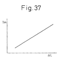
- the DC high voltage of the battery 41 is converted by the motor drive control circuit 40 to a three-phase AC current having a frequency fm and a current value Im.
- This three-phase alternating current is supplied to the exciting coil of the stator 39.
- the frequency fm is the frequency required for making the rotating field generated by the exciting coil rotate in synchronization with the rotation of the rotor 38.
- the frequency fm is calculated by the CPU 54 based on the rotational speed of the output shaft 36. In the motor drive control circuit 40, this frequency fm is made the frequency of a three-phase alternating current.
- the output torque of the electric motor 37 is substantially proportional to the current value Im of the three-phase alternating current.
- the current value Im is calculated by the CPU 54 based on the requested output torque of the electric motor 37. In the motor drive control circuit 40, this current value Im is made the current value of the three-phase alternating current.
- the electric motor 37 when the electric motor is in a state driven by outside force, the electric motor 37 operates as a generator. The electric power generated at that time is stored in the battery 41. Whether or not the electric motor 37 should be driven by outside force is judged by the CPU 54. When it is judged that the electric motor 37 is to be driven by outside force, the motor drive control circuit 40 operates so that the electric power generated by the electric motor 37 is stored in the battery 41.
- FIG. 3 shows another embodiment of a compression ignition type engine.
- the transmission 35 is connected to the output shaft of the electric motor 37.
- the rotor 38 of the electric motor 37 is attached to the output shaft 47 of the engine. Therefore, the rotor 38 rotates together with the output shaft 47 of the engine at all times.
- the transmission 35 it is possible to use an ordinary automatic transmission provided with a torque converter, various types of variable speed transmissions, an automatic transmission of a type enabling automatic clutch operation and gear changing operation in a manual transmission provided with a clutch, or a manual transmission.
- the ordinate TQ in FIG. 4 shows the required torque with respect to the engine.
- the abscissa N shows the engine rotational speed.
- the solid lines show the relationship between the required torque at the same amount of depression of the accelerator pedal 44 and the engine rotational speed N. Further, the solid line A in FIG. 4 shows when the amount of depression of the accelerator pedal 44 is zero, while the solid line B shows when the amount of depression of the accelerator pedal 44 is maximum. The amount of depression of the accelerator pedal 44 increases from the solid line A to the solid line B.
- the required torque TQ in accordance with the amount of depression L of the accelerator pedal 44 and the engine rotational speed N is first calculated from the relationship shown in FIG. 4. The amount of fuel injection etc. are calculated based on the required torque TQ.
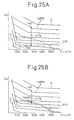
- FIG. 5 shows an example of an experiment showing the change in output torque and the change in the amount of exhaust of smoke, hydrocarbons, carbon monoxide, and NO x when changing the air-fuel ratio A/F (abscissa in FIG. 5) by changing the opening degree of the throttle valve 21 and the EGR rate at the time of low load operation of the engine.
- A/F abcissa in FIG. 5
- the EGR rate became at least 65 percent.
- the EGR rate becomes close to 40 percent.
- the air-fuel ratio A/F becomes about 30
- the amount of smoke generated starts to increase.
- the EGR rate is further raised and the air-fuel ratio A/F made smaller, the amount of smoke generated rapidly increases then peaks.
- the EGR rate is further raised and the air-fuel ratio A/F made smaller, the smoke then rapidly decreases.
- the smoke produced becomes substantially zero. That is, almost no soot is produced any longer. At this time, the output torque of the engine falls somewhat and the amount of NO x generated drops considerably.
- the amounts of hydrocarbons and carbon monoxide generated start to increase.
- FIG. 6A shows the changes in compression pressure in the combustion chamber 5 when the amount of smoke produced is the greatest near an air-fuel ratio A/F of 21.
- FIG. 6B shows the changes in compression pressure in the combustion chamber 5 when the amount of smoke produced is substantially zero near an air-fuel ratio A/F of 18.
- the combustion pressure is lower in the case shown in FIG. 6B where the amount of smoke produced is substantially zero than the case shown in FIG. 6A where the amount of smoke produced is large.
- the amount of smoke produced that is, the amount of soot produced
- the amounts of hydrocarbons and carbon monoxide exhausted increase.
- the hydrocarbons are exhausted without growing into soot. That is, when the straight chain hydrocarbons and aromatic hydrocarbons contained in the fuel are raised in temperature in an oxygen poor state, they decompose due to the heat resulting in the formation of a precursor of soot.
- soot mainly comprised of solid masses of carbon atoms is produced. In this case, the actual process of production of soot is complicated. How the precursor of soot is formed is not clear, but whatever the case, the hydrocarbons contained in the fuel grow to soot through the soot precursor.
- the temperature of the fuel and its surroundings when the process of production of hydrocarbons stops in the state of the soot precursor that is, the above certain temperature
- soot precursor or a state of hydrocarbons before this can be easily removed by after-treatment using a catalyst having an oxidation action etc.
- a catalyst having an oxidation action etc. there is an extremely great difference between whether the hydrocarbons are exhausted from the combustion chamber 5 in the form of a soot precursor or a state before that or exhausted from the combustion chamber 5 in the form of soot.
- the vaporized fuel will immediately react with the oxygen in the air and burn.
- the temperature of the air away from the fuel does not rise that much. Only the temperature around the fuel becomes locally extremely high. That is, at this time, the air away from the fuel does not absorb the heat of combustion of the fuel much at all. In this case, since the combustion temperature becomes extremely high locally, the unburned hydrocarbons receiving the heat of combustion produce soot.
- the inert gas is preferably a gas with a large specific heat.
- CO 2 and EGR gas have relatively large specific heats, it may be said to be preferable to use CO 2 or EGR gas as the inert gas.
- FIG. 7 shows the relationship between the EGR rate and smoke when changing the degree of cooling of the EGR gas using the EGR gas as an inert gas. That is, in FIG. 7, the curve A shows the case when force cooling the EGR gas to maintain the temperature of the EGR gas at about 90°C, the curve B shows the case when cooling the EGR gas by a small sized cooling device, and the curve C shows the case when not force cooling the EGR gas.
- the amount of soot produced peaks when the EGR rate becomes slightly lower than 50 percent. In this case, almost no soot is produced any longer when the EGR rate is made at least about 55 percent.
- the amount of soot produced peaks when the EGR rate is near 55 percent. In this case, almost no soot is produced any longer when the EGR rate is made at least about 70 percent.
- FIG. 7 shows the amount of smoke produced when the engine load is relatively high.
- the EGR rate where the amount of soot produced peaks falls somewhat and the lower limit of the EGR rate where almost no soot is produced any longer falls somewhat as well.
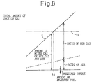
- FIG. 8 shows the amount of mixed gas of EGR gas and air, the ratio of air in the mixed gas, and the ratio of EGR gas in the mixed gas required for making the temperature of the fuel and the gas around it at the time of combustion a temperature lower than the temperature at which soot is produced in the case of use of EGR gas as an inert gas.
- the ordinate shows the total amount of suction gas taken into the combustion chamber 5.
- the broken line Y shows the total amount of suction gas able to be taken into the combustion chamber 5 when supercharging is not being performed.
- the abscissa shows the required torque.
- the ratio of air that is, the amount of air in the mixed gas
- the ratio of air and the amount of injected fuel becomes the stoichiometric air-fuel ratio.
- the ratio of EGR gas that is, the amount of EGR gas in the mixed gas
- This amount of EGR gas is, expressed in terms of the EGR rate, about at least 55 percent and, in the embodiment shown in FIG. 8, is at least 70 percent.
- the temperature of the fuel and the gas around it becomes a temperature lower than the temperature at which soot is produced and therefore no soot at all is produced any longer.
- the amount of NO x produced at this time is around 10 ppm or less and therefore the amount of NO x produced becomes extremely small.
- the amount of fuel injected increases, the amount of heat generated at the time of combustion increases, so to maintain the temperature of the fuel and the gas around it at a temperature lower than the temperature at which soot is produced, the amount of heat absorbed by the EGR gas must be increased. Therefore, as shown in FIG. 8, the amount of EGR gas has to be increased the greater the amount of injected fuel. That is, the amount of EGR gas has to be increased as the required load becomes higher.
- the EGR gas is made to recirculate through the EGR passage 27 to the inlet side of the supercharger, that is, in the intake duct 17 upstream of the compressor 16 of the exhaust turbocharger 15, it is possible to maintain the EGR rate at 55 percent or more, for example, at 70 percent, in the region where the required load is larger than L 0 and therefore it is possible to maintain the temperature of the fuel and the gas around it at a temperature lower than the temperature at which soot is produced.
- the EGR rate of the suction gas raised in pressure by the compressor 16 of the exhaust turbocharger 15 also becomes 70 percent and therefore it is possible to maintain the temperature of the fuel and the gas around it at a temperature lower than the temperature at which soot is produced to the extent by which pressure can be raised by the compressor 16. Therefore, it becomes possible to enlarge the operating region of the engine at which low temperature combustion can be caused.
- FIG. 8 shows the case of combustion of fuel at the stoichiometric air-fuel ratio. Even if the amount of air is made smaller than the amount of air shown in FIG. 8, that is, even if the air-fuel ratio is made rich, it is possible to obstruct the production of soot and make the amount of NO x produced around 10 ppm or less. Further, even if the amount of air is made greater than the amount of air shown in FIG. 8, that is, the average value of the air-fuel ratio is made a lean of 17 to 18, it is possible to obstruct the production of soot and make the amount of NO x produced around 10 ppm or less.
- the solid line in FIG. 9A shows the relationship between the average gas temperature Tg in the combustion chamber 5 and the crank angle when low temperature combustion is performed.
- the broken line in FIG. 9A shows the relationship between the average gas temperature Tg in the combustion chamber 5 and the crank angle when ordinary combustion is performed.
- the solid line in FIG. 9B shows the relationship between the temperature Tf of the fuel and the gas surrounding it and the crank angle when low temperature combustion is being performed.
- the broken line in FIG. 9B shows the relationship between the temperature Tf of the fuel and the gas surrounding it and the crank angle when ordinary combustion is being performed.
- the average temperature Tg of the gas in the combustion chamber 5 near top dead center of the compression stroke becomes higher when low temperature combustion is being performed compared with when ordinary combustion is being performed.
- the temperature of the burned gas in the combustion chamber 5 after the end of combustion becomes higher when low temperature combustion is being performed compared with when ordinary combustion is being performed. Therefore if low temperature combustion is performed, the temperature of the exhaust gas rises.
- the first combustion that is, the low temperature combustion
- the second combustion that is, the conventionally normally performed combustion
- the second combustion means combustion where the amount of inert gas in the combustion chamber is smaller than the amount of inert gas where the amount of production of soot peaks.
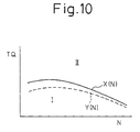
- FIG. 10 shows a first operating region I where the first combustion, that is, the low temperature combustion, is performed and a second operating region II where the second combustion, that is, the combustion by the conventional combustion method, is performed. Note that in FIG.
- the abscissa TQ shows the required torque
- the ordinate N shows the engine rotational speed.
- X(N) shows a first boundary between the first operating region I and the second operating region II
- Y(N) shows a second boundary between the first operating region I and the second operating region II.
- the change of the operating region from the first operating region I to the second operating region II is judged based on the first boundary X(N), while the change of the operating region from the second operating region II to the first operating region I is judged based on the second boundary Y(N).
- the two boundaries that is, the first boundary X(N) and the second boundary Y(N) at the lower load side from the first boundary X(N), are provided for the following two reasons.
- the first reason is that at the high load side of the second operating region II, the combustion temperature is relatively high and even if the required torque TQ becomes lower than the first boundary X(N) at that time, low temperature combustion cannot be performed immediately. That is, unless the required torque TQ becomes considerably low, that is, becomes lower than the second boundary Y(N), low temperature combustion cannot be started immediately.
- the second reason is to provide hysteresis with respect to the change of the operating regions between the first operating region I and the second operating region II.
- Figure 11 shows the opening degree of the throttle valve 21, the opening degree of the EGR control valve 29, the EGR rate, the air-fuel ratio, the injection timing, and the amount of injection with respect to the required torque TQ.
- the opening degree of the throttle valve 21 is gradually increased from close to the fully closed state to the 2/3 opened state as the required torque TQ becomes higher, while the opening degree of the EGR control valve 29 is gradually increased from close to the fully closed state to the fully opened state as the required torque TQ becomes higher.
- the EGR rate is made about 70 percent and the air-fuel ratio is made a slightly lean air-fuel ratio.
- the opening degree of the throttle valve 21 and the opening degree of the EGR control valve 29 are controlled so that the EGR rate becomes about 70 percent and the air-fuel ratio becomes a slightly lean air-fuel ratio.
- the fuel is injected before top dead center of the compression stroke TDC.
- the injection start timing ⁇ S becomes later the higher the required torque TQ.
- the injection end timing ⁇ E also becomes later the later the injection start timing ⁇ S.
- the throttle valve 21 is made to close to close to the fully closed state.
- the EGR control valve 29 is also made to close to close to the fully closed state. If the throttle valve 21 closes to close to the fully closed state, the pressure in the combustion chamber 5 at the start of compression will become low, so the compression pressure will become small. If the compression pressure becomes small, the amount of compression work by the piston 4 becomes small, so the vibration of the engine body 1 becomes smaller. That is, during idling operation, the throttle valve 21 can be closed to close to the fully closed state to suppress vibration in the engine body 1.
- the opening degree of the throttle valve 21 is made to increase in steps from the 2/3 opened state to the fully opened state.
- the EGR rate is made to be reduced in steps from about 70 percent to not more than 40 percent and the air-fuel ratio is enlarged in steps. That is, since the EGR rate jumps over the range of EGR rate where a large amount of smoke is produced (FIG. 7), a large amount of smoke is no longer produced when the engine operating region changes from the first operating region I to the second operating region II.
- the second combustion that is, the conventionally performed combustion
- the heat efficiency is higher than with low temperature combustion and therefore when the engine operating region changes from the first operating region I to the second operating region II, as shown in FIG. 11, the amount of injection is made to be reduced in steps.
- the throttle valve 21 is except in some cases held in the fully opened state and the opening degree of the EGR control valve 29 is made smaller the higher the required torque TQ.
- the EGR rate becomes lower the higher the required torque TQ and the air-fuel ratio becomes smaller the higher the required torque TQ. Even if the required torque TQ becomes high, however, the air-fuel ratio is made a lean air-fuel ratio.
- the injection start timing ⁇ S is made close to the top dead center of the compression stroke TDC.
- FIG. 12 shows the air-fuel ratio A/F in the first operating region I.
- the air-fuel ratios of the curves are determined by proportional distribution. As shown in FIG. 12, in the first operating region, the air-fuel ratio becomes lean. Further, in the first operating region I, the air-fuel ratio A/F is made leaner the lower the required torque TQ.
- the air-fuel ratio A/F is made larger as the required torque TQ becomes lower.
- the amount of injection Q in the first operating region I is stored in advance in the ROM 52 in the form of a map as a function of the required torque TQ and the engine rotational speed N as shown in FIG. 13A.
- the injection start timing ⁇ S in the first operating region I, as shown in FIG. 13B, is stored in advance in the ROM 52 in the form of a map as a function of the required torque TQ and engine rotational speed N.
- the target opening degree ST of the throttle valve 21 necessary for making the air-fuel ratio the target air-fuel ratio A/F shown in FIG. 12 according to the engine operating state and making the EGR rate the target EGR rate according to the engine operating state is stored in advance in the ROM 52 in the form of a map as a function of the required torque TQ and the engine rotational speed N as shown in FIG. 14A.
- the target opening degree SE of the EGR valve 29 necessary for making the air-fuel ratio the target air-fuel ratio A/F shown in FIG. 12 according to the engine operating state and making the EGR rate the target EGR rate according to the engine operating state is stored in advance in the ROM 52 in the form of a map as a function of the required torque TQ and the engine rotational speed N as shown in FIG. 14B.
- the amount of injection Q at the time of the second combustion is stored in advance in the ROM 52 in the form of a map as a function of the required torque TQ and the engine rotational speed N as shown in FIG. 16A.
- the injection start timing ⁇ S at the time of the second combustion is stored in advance in the ROM 52 in the form of a map as a function of the required torque TQ and the engine rotational speed N as shown in FIG. 16B.
- the target opening degree ST of the throttle valve 21 necessary for making the air-fuel ratio the target air-fuel ratio A/F shown in FIG. 15 according to the engine operating state and making the EGR rate the target EGR rate according to the engine operating state is stored in advance in the ROM 52 in the form of a map as a function of the required torque TQ and the engine rotational speed N as shown in FIG. 17A.
- the target opening degree SE of the EGR valve 29 necessary for making the air-fuel ratio the target air-fuel ratio A/F shown in FIG. 15 according to the engine operating state and making the EGR rate the target EGR rate according to the engine operating state is stored in advance in the ROM 52 in the form of a map as a function of the required torque TQ and the engine rotational speed N as shown in FIG. 17B.
- FIG. 18A is a front view of the particulate filter 24, while FIG. 18B is a side sectional view of the particulate filter.
- the particulate filter 24 forms a honeycomb structure and is provided with a plurality of exhaust circulation passages 60 and 61 extending in parallel with each other. These exhaust circulation passages are comprised by exhaust gas inflow passages 60 with one ends sealed by plugs 62 and exhaust gas outflow passages 61 with other ends sealed by plugs 63. Note that the hatched portions in FIG. 18A show plugs 63.
- the exhaust gas inflow passages 60 and the exhaust gas outflow passages 61 are arranged alternately through thin wall partitions 64.
- the exhaust gas inflow passages 60 and the exhaust gas outflow passages 61 are arranged so that each exhaust gas inflow passage 60 is surrounded by four exhaust gas outflow passages 61, and each exhaust gas outflow passage 61 is surrounded by four exhaust gas inflow passages 60.
- the particulate filter 24 is formed from a porous material such as for example cordierite. Therefore, when exhaust gas is sent into the particulate filter from the X-direction in FIG. 18B, the exhaust gas flowing into the exhaust gas inflow passages 60 flows out into the adjoining exhaust gas outflow passages 61 through the surrounding partitions 64 as shown by the arrows.
- a layer of a carrier comprised of for example alumina is formed on the peripheral surfaces of the exhaust gas passages 60 and 61, that is, the two side surfaces of the partitions 64 and the inside walls of the fine holes in the partitions 64.
- a precious metal catalyst and an active oxygen release agent which absorbs the oxygen and holds the oxygen if excess oxygen is present in the surroundings and releases the held oxygen in the form of active oxygen if the concentration of the oxygen in the surroundings falls.
- platinum Pt is used as the precious metal catalyst.
- the active oxygen release agent use is made of at least one of an alkali metal such as potassium K, sodium Na, lithium Li, cesium Cs, and rubidium Rb, an alkali earth metal such as barium Ba, calcium Ca, and strontium Sr, a rare earth such as lanthanum La, yttrium Y, and cerium Ce, and a transition metal.
- the active oxygen release agent use is preferably made of an alkali metal or an alkali earth metal with a higher tendency of ionization than calcium Ca, that is, potassium K, lithium Li, cesium Cs, rubidium Rb, barium Ba, and strontium Sr.
- the action of removal of the particulate in the exhaust gas by the particulate filter 24 will be explained taking as an example the case of carrying platinum Pt and potassium K on a carrier, but the same type of action for removal of particulate is performed even when using another precious metal, alkali metal, alkali earth metal, rare earth, and transition metal.
- the exhaust gas contains a large amount of excess air. That is, if the ratio of the air and fuel fed into the intake passage, combustion chamber 5, and exhaust passage is called the air-fuel ratio of the exhaust gas, then in a compression ignition type engine such as shown in FIG. 1 and FIG. 3, the air-fuel ratio of the exhaust gas becomes lean. Further, in the combustion chamber 5, NO is generated, so the exhaust gas contains NO. Further, the fuel contains sulfur S. This sulfur S reacts with the oxygen in the combustion chamber 5 to become SO 2 . Therefore, the fuel contains SO 2 . Accordingly, when exhaust gas is fed into the exhaust gas inflow passages 60 of the particulate filter 24, exhaust gas containing excess oxygen, NO, and SO 2 flows into the exhaust gas inflow passages 60 of the particulate filter 24.
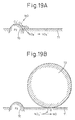
- FIGS. 19A and 19B are enlarged views of the surface of the carrier layer formed on the inner peripheral surfaces of the exhaust gas inflow passages 60 and the inside walls of the fine holes in the partitions 64. Note that in FIGS. 19A and 19B, 70 indicates particles of platinum Pt, while 71 indicates the active oxygen release agent containing potassium K.
- the exhaust gas also contains SO 2 .
- This SO 2 is absorbed in the active oxygen release agent 71 by a mechanism similar to that of NO. That is, in the above way, the oxygen O 2 adheres to the surface of the platinum Pt in the form of O 2 - or O 2- .
- the SO 2 in the exhaust gas reacts with the O 2 - or O 2- on the surface of the platinum Pt to become SO 3 .
- part of the SO 3 which is produced is absorbed in the active oxygen release agent 71 while being oxidized on the platinum Pt and diffuses in the active oxygen release agent 71 in the form of sulfate ions SO 4 2- while bonding with the potassium K to produce potassium sulfate K 2 SO 4 .
- potassium nitrate KNO 3 and potassium sulfate K 2 SO 4 are produced in the active oxygen release agent 71.
- particulate comprised of mainly carbon that is, soot
- the exhaust gas contains this particulate.
- the amount of particulate in the exhaust gas becomes extremely small.
- the particulate contained in the exhaust gas contacts and adheres to the surface of the carrier layer, for example, the surface of the active oxygen release agent 71, as shown in FIG. 19B when the exhaust gas is flowing through the exhaust gas inflow passages 60 of the particulate filter 24 or when flowing from the exhaust gas inflow passages 60 to the exhaust gas outflow passages 61.
- the concentration of oxygen at the contact surface of the particulate 72 and the active oxygen release agent 71 falls. If the concentration of oxygen falls, a difference in concentration occurs with the inside of the high oxygen concentration active oxygen release agent 71 and therefore the oxygen in the active oxygen release agent 71 moves toward the contact surface between the particulate 72 and the active oxygen release agent 71. As a result, the potassium nitrate KNO 3 formed in the active oxygen release agent 71 is broken down into potassium K, oxygen O, and NO. The oxygen O heads toward the contact surface between the particulate 72 and the active oxygen release agent 71, while the NO is released from the active oxygen release agent 71 to the outside. The NO released to the outside is oxidized on the downstream side platinum Pt and is again absorbed in the active oxygen release agent 71.
- the potassium sulfate K 2 SO 4 formed in the active oxygen release agent 71 is also broken down into potassium K, oxygen O, and SO 2 .
- the oxygen O heads toward the contact surface between the particulate 72 and the active oxygen release agent 71, while the SO 2 is released from the active oxygen release agent 71 to the outside.
- the SO 2 released to the outside is oxidized on the downstream side platinum Pt and again absorbed in the active oxygen release agent 71.
- the oxygen O heading toward the contact surface between the particulate 72 and the active oxygen release agent 71 is the oxygen broken down from compounds such as potassium nitrate KNO 3 or potassium sulfate K 2 SO 4 .
- the oxygen O broken down from these compounds has a high energy and has an extremely high activity. Therefore, the oxygen heading toward the contact surface between the particulate 72 and the active oxygen release agent 71 becomes active oxygen O. If this active oxygen O contacts the particulate 72, the particulate 72 is oxidized without emitting a luminous flame in a short period and the particulate 72 is completely eliminated. Note that the particulate 72 deposited on the particulate filter 24 in this way is oxidized by the active oxygen O, but the particulate 72 is also oxidized by the oxygen in the exhaust gas.
- the particulate filter 24 When the particulate deposited in layers on the particulate filter 24 is burned, the particulate filter 24 becomes red hot and burns along with a flame. This burning along with a flame does not continue unless the temperature is high. Therefore, to continue burning along with such flame, the temperature of the particulate filter 24 must be maintained at a high temperature.
- the particulate 72 is oxidized without emitting a luminous flame as explained above.
- the surface of the particulate filter 24 does not become red hot. That is, in other words, in this embodiment of the present invention, the particulate 72 is removed by oxidation by a considerably low temperature. Accordingly, the action of removal of the particulate 72 by oxidation without emitting a luminous flame according to this embodiment of the present invention is completely different from the action of removal of particulate by burning accompanied with a flame.
- the platinum Pt and the active oxygen release agent 71 become more active the higher the temperature of the particulate filter 24, so the amount of the active oxygen O able to be released by the active oxygen release agent 71 per unit time increases the higher the temperature of the particulate filter 24. Therefore, the amount of the particulate removable by oxidation per unit time without emitting a luminous flame on the particulate filter 24 increases the higher the temperature of the particulate filter 24.
- the solid line in FIG. 21 shows the amount G of the particulate removable by oxidation per unit time without emitting a luminous flame.
- the abscissa of FIG. 21 shows the temperature TF of the particulate filter 24. If the amount of particulate exhausted from the combustion chamber 5 per unit time is called the amount of discharged particulate M, when the amount of discharged particulate M is smaller than the amount G of particulate removable by oxidation, that is, in the region I of FIG. 21, when contacting the particulate filter 24, all of the particulate discharged from the combustion chamber 5 is removed by oxidation successively in a short time without emitting a luminous flame on the particulate filter 24.
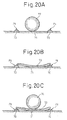
- FIGS. 20A to 20C show the state of oxidation of particulate in this case.
- This residual particulate portion 73 covering the surface of the carrier layer gradually changes to hard-to-oxidize carbon and therefore the residual particulate portion 73 easily remains as it is. Further, if the surface of the carrier layer is covered by the residual particulate portion 73, the action of oxidation of the NO and SO 2 by the platinum Pt and the action of release of the active oxygen from the active oxygen release agent 71 are suppressed. As a result, as shown in FIG. 20C, other particulate 74 successively deposits on the residual particulate portion 73. That is, the particulate deposits in layers.
- particulate deposits in layers in this way, the particulate is separated in distance from the platinum Pt or the active oxygen release agent 71, so even if easily oxidizable particulate, it will not be oxidized by active oxygen O. Therefore, other particulate successively deposits on the particulate 74. That is, if the state of the amount M of discharged particulate being larger than the amount G of particulate removable by oxidation continues, particulate deposits in layers on the particulate filter 24 and therefore unless the temperature of the exhaust gas is made higher or the temperature of the particulate filter 24 is made higher, it is no longer possible to cause the deposited particulate to ignite and burn.
- the particulate is burned in a short time without emitting a luminous flame on the particulate filter 24.
- the particulate deposits in layers on the particulate filter 24. Therefore, to prevent the particulate from depositing in layers on the particulate filter 24, the amount M of discharged particulate has to be kept smaller than the amount G of the particulate removable by oxidation at all times.
- the particulate filter 24 used in this embodiment of the present invention can be oxidized even if the temperature TF of the particulate filter 24 is considerably low. Therefore, in a compression ignition type engine shown in FIG. 1 and FIG. 3, it is possible to maintain the amount M of the discharged particulate and the temperature TF of the particulate filter 24 so that the amount M of discharged particulate normally becomes smaller than the amount G of the particulate removable by oxidation. Therefore, in this embodiment of the present invention, the amount M of discharged particulate and the temperature TF of the particulate filter 24 are maintained so that the amount M of discharged particulate usually becomes smaller than the amount G of the particulate removable by oxidation.
- the particulate no longer deposits in layers on the particulate filter 24.
- the pressure loss of the flow of exhaust gas in the particulate filter 24 is maintained at a substantially constant minimum pressure loss to the extent of being able to be said to not change much at all. Therefore, it is possible to maintain the drop in output of the engine at a minimum.
- the action of removal of particulate by oxidation of the particulate takes place even at a considerably low temperature. Therefore, the temperature of the particulate filter 24 does not rise that much at all and consequently there is almost no risk of deterioration of the particulate filter 24. Further, since the particulate does not deposit in layers on the particulate filter 24, there is no danger of coagulation of ash and therefore there is less danger of the particulate filter 24 clogging.
- This clogging however occurs mainly due to the calcium sulfate CaSO 4 . That is, fuel or lubrication oil contains calcium Ca. Therefore, the exhaust gas contains calcium Ca. This calcium Ca produces calcium sulfate CaSO 4 in the presence of SO 3 . This calcium sulfate CaSO 4 is a solid and will not break down by heat even at a high temperature. Therefore, if calcium sulfate CaSO 4 is produced and the fine holes of the particulate filter 24 are clogged by this calcium sulfate CaSO 4 , clogging occurs.
- an alkali metal or an alkali earth metal having a higher tendency toward ionization than calcium Ca for example potassium K
- the SO 3 diffused in the active oxygen release agent 71 bonds with the potassium K to form potassium sulfate K 2 SO 4 .
- the calcium Ca passes through the partitions 74 of the particulate filter 24 and flows out into the exhaust gas passages 60 or 61 without bonding with the SO 3 . Therefore, there is no longer any clogging of fine holes of the particulate filter 24.
- an alkali metal or an alkali earth metal having a higher tendency toward ionization than calcium Ca that is, potassium K, lithium Li, cesium Cs, rubidium Rb, barium Ba, and strontium Sr, as the active oxygen release agent 71.
- the intention is basically to maintain the amount M of the discharged particulate smaller than the amount G of the particulate removable by oxidation in all operating states.
- the particulate filter 24 is low in temperature, therefore at this time the amount M of discharged particulate becomes greater than the amount G of particulate removable by oxidation. Therefore, in this embodiment of the present invention, except for special cases such as right after engine startup, the amount M of discharged particulate is made to become smaller than the amount G of particulate removable by oxidation.
- the amount M of discharged particulate becomes greater than the amount G of particulate removable by oxidation such as right after engine startup, a portion of the particulate not oxidized starts to remain on the particulate filter 24.
- the part of the particulate which failed to be oxidized starts remaining in this way, that is, when the particulate only deposits up to a certain limit, if the amount M of discharged particulate becomes less than the amount G of particulate removable by oxidation, the portion of the residual particulate will be removed by oxidation without emitting a luminous flame due to the active oxygen O.
- the amount M of discharged particulate becomes less than the amount G of particulate removable by oxidation, the amount M of discharged particulate and the temperature TF of the particulate filter 24 are maintained so that only an amount of particulate less than the certain limit which can be removed by oxidation deposits on the particulate filter 24.
- the air-fuel ratio of all or part of the exhaust gas is temporarily made rich, the particulate deposited on the particulate filter 24 will be oxidized without emitting a luminous flame. That is, if the air-fuel ratio of the exhaust gas is made rich, that is, if the concentration of oxygen in the exhaust gas is reduced, the active oxygen O is released all at once from the active oxygen release agent 71 to the outside.
- the particulate deposited can be removed by oxygen in a short time without emitting a luminous flame by the active oxygen O released all at once in this way.
- a layer of a carrier comprised of for example alumina is formed on the two side surfaces of the partition walls 64 and the inner wall surfaces of the fine holes in the partition walls 64 of the particulate filter 24.
- a precious metal catalyst and active oxygen release agent are carried on the carrier.
- the carrier carry an NO x absorbent which absorbs the NO x contained in the exhaust gas when the air-fuel ratio of the exhaust gas flowing into the particulate filter 24 on this carrier is lean and releases the NO x absorbed when the air-fuel ratio of the exhaust gas flowing into the particulate filter 24 becomes the stoichiometric air-fuel ratio or rich.
- platinum Pt is used as the precious metal.
- the NO x absorbent use is made of at least one of an alkali metal such as potassium K, sodium Na, lithium Li, cesium Cs, and rubidium Rb, an alkali earth metal such as barium Ba, calcium Ca, and strontium Sr, and a rare earth such as lanthanum La and yttrium Y. Note that as will be understood from a comparison with the metal comprising the above active oxygen release agent, the metals comprising the NO x absorbent and the metals comprising the active oxygen release agent match in large part.
- part of the NO 2 produced is absorbed in the NO x absorbent 71 while being oxidized on the platinum Pt and diffuses in the NO x absorbent 71 in the form of nitrate ions NO 3 - as shown in FIG. 19A while bonding with the potassium K.
- Part of the nitrate ions NO 3 - produces potassium nitrate KNO 3 . In this way, NO is absorbed in the NO x absorbent 71.
- the same metal is used for the NO x absorbent and the active oxygen release agent.
- the functions of both the function of the NO x absorbent and the function of the active oxygen release agent described above are simultaneously achieved.
- An agent which simultaneously achieves both these functions is referred to below as an active oxygen release agent/NO x absorbent.
- reference numeral 71 in FIG. 19A shows the active oxygen release agent/NO x absorbent.
- the action of release of active oxygen from the active oxygen release agent 71 as already explained with reference to FIG. 21 is started when the temperature of the particulate filter 24 is considerably low. The same is true when using this active oxygen release agent/NO x absorbent 71. As opposed to this, the action of absorption of NO x to the NO x absorbent or the active oxygen release agent/NO x absorbent 71 is not started until the temperature TF of the particulate filter 24 becomes higher than the temperature of the start of release of the active oxygen. This is believed to be due to the fact that release of active oxygen occurs by stripping oxygen from for example the potassium nitrate KNO 3 , while the action of absorption of NO x does not start unless the platinum Pt is activated.
- FIG. 22 shows the amount G of particulate removable by oxidation and the NO x absorption rate when using potassium K as the NO x absorbent or the active oxygen release agent/NO x absorbent 71. From FIG. 22, the action of release of active oxygen starts when the temperature TF of the particulate filter 24 is less than 200°C, while the active of absorption of NO x does not start until the temperature TF of the particulate filter 24 is over 200°C.
- the action of release of active oxygen becomes greater the higher the temperature TF of the particulate filter 24.
- the action of absorption of NO x disappears when the temperature TF of the particulate filter 24 rises. That is, when the temperature TF of the particulate filter 24 exceeds a certain temperature, in the example shown in FIG. 22, over about 500°C, the nitrate ions NO 3 - or potassium nitrate KNO 3 is decomposed due to the heat and NO is released from the active oxygen release agent/NO x absorbent 71.
- the amount of release of NO becomes greater than the amount of absorption of NO x and therefore the NO x absorption rate falls as shown in FIG. 22.
- FIG. 22 shows the NO x absorption rate when using potassium K as the active oxygen release agent/NO x absorbent 71.
- the temperature range of the particulate filter 24 where the NO x absorption rate becomes higher differs depending on the metal used. For example, when using barium Ba as the NO x absorbent or active oxygen release agent/NO x absorbent 71, the temperature range of the particulate filter 24 where the NO x absorption rate becomes higher becomes narrower than when using potassium K shown in FIG. 22.
- the temperature range of the particulate filter 24 where the action of absorbing NO x is performed has to be made the temperature range where the NO x absorption rate is more than a certain value, for example, more than 50 percent. Therefore, when using potassium K as the NO x absorbent or active oxygen release agent/NO x absorbent 71, as will be understood from FIG. 22, it is necessary to maintain the temperature TF of the particulate filter 24 between about 250°C to 500°C.
- the amount M of discharged particulate is maintained to be smaller than the amount G of particulate removable by oxidation and the temperature TF of the particulate filter 24 is maintained within the temperature range where the NO x absorption rate of the particulate filter 24 becomes more than a certain value. That is, the amount M of discharged particulate and the temperature TF of the particulate filter 24 are maintained within the particulate/NO x simultaneous processing region shown by the hatching in FIG. 22.
- At least one of the amount M of discharged particulate and the temperature TF of the particulate filter 24 is controlled so that the amount M of discharged particulate and the temperature TF of the particulate filter 24 fall within the particulate/NO x simultaneous processing region.
- NO x absorbent 71 there is a limit to the NO x absorbing ability of the NO x absorbent 71 or active oxygen release agent/NO x absorbent 71 (hereinafter these will be referred to overall as simply the "NO x absorbent 71"). It is necessary to release the NO x from the NO x absorbent 71 before the NO x absorption ability of the NO x absorbent 71 becomes saturated. Therefore, it is necessary to estimate the amount of NO x absorbed in the NO x absorbent 71. Therefore, in the present invention, the amount A of absorption of NO x per unit time at the time of the first combustion is found in advance in the form of a map as shown in FIG.
- the amount B of absorption of NO x per unit time at the time of the second combustion is set in advance in the form of a map as shown in FIG. 23B as a function of the required torque TQ and engine rotational speed N, and these amounts A and B of absorption of NO x per unit time are cumulatively added to estimate the NO x amount ⁇ NOX absorbed in the NO x absorbent 71.
- the NO x absorption ⁇ NOX exceeds a predetermined allowable maximum value MAX, the NO x is made to be released from the NO x absorbent 71.
- the amount of fuel injection is increased to make the air-fuel ratio A/F in the combustion chamber 5 temporarily rich. If the air-fuel ratio A/F in the combustion chamber 5 is made rich, the NO x is released from the NO x absorbent 71.
- the time of the first combustion that is, low temperature combustion, even if the air-fuel ratio A/F in the combustion chamber 5 is made rich, no soot is generated and therefore it is possible to release NO x from the NO x absorbent 71 without the generation of soot.
- the second combustion when the NO x absorption ⁇ NOX exceeds the allowable maximum value MAX and the amount of fuel injection is increased to make the air-fuel ratio A/F in the combustion chamber 5 rich, a large amount of soot is generated. Therefore, in this embodiment of the present invention, at the time of the second combustion, when the NO x absorption ⁇ NOX exceeds the allowable maximum value MAX, the second combustion is switched to the first combustion and the air-fuel ratio A/F in the combustion chamber 5 is made rich under the first combustion. As explained above, by making the air-fuel ratio A/F in the combustion chamber 5 rich, no soot is generated and therefore it is possible to release NO x from the NO x absorbent 71 without the generation of soot even at the time of the second combustion.
- the electric motor 37 when switching from the second combustion to the first combustion, the electric motor 37 is driven to make the electric motor 37 generate an output torque substantially equal to the drop in engine output torque due to the reduction in the amount of injection.
- the electric motor 37 operates well only when more than a certain amount of electrical energy is stored in the battery 41.
- the amount of electrical energy stored in the battery 41 falls below that amount, it is difficult to get the electric motor 37 to operate well. Therefore, the drop in the engine output torque can be made up for by the output torque of the electric motor 37 only when there is sufficient leeway before the amount of electrical energy stored in the battery 41 falls below the above value even when operating the electric motor 37, that is, when the amount of electrical energy is larger than a predetermined setting with sufficient leeway before it falls below the above value.
- the second combustion when the NO x absorption ⁇ NOX exceeds the allowable maximum value MAX, if the amount of electrical energy stored in the battery 41 is larger than the predetermined setting, the second combustion is switched to the first combustion and the drop in the engine output torque is made up for by the output torque of the electric motor 37.
- the second combustion when the NO x absorption ⁇ NOX exceeds the allowable maximum value MAX and the amount of electrical energy stored in the battery 41 is smaller than the predetermined setting, the second combustion is not switched to the first combustion, but the second combustion is maintained as it is and the electric motor 37 is not operated.
- additional fuel is injected from the fuel injector 6 in the second half of the expansion stroke or in the exhaust stroke or additional fuel is fed into the exhaust passage upstream of the NO x absorbent 71 so that the air-fuel ratio of the exhaust gas becomes temporarily rich.
- FIG. 24A shows the relationship between the electric power stored in the battery when using a nickel-metal hydride battery as the battery 41, that is, the amount B (W) of electrical energy, and battery voltage V. Note that in FIG. 24A, Bmax shows the maximum electrical energy stored, while Bd shows the setting forming the criteria for judgement as to whether to operate the electric motor 37.
- the amount B of electrical energy stored in the battery 41 is calculated by the calculation routine shown in FIG. 24B. That is, if the discharge current I is made positive, the charge current I is made negative, and the voltage of the battery 41 is V, the amount of stored electrical energy changing due to the charging or discharging action is expressed as V ⁇ I, so the amount B of stored electrical energy can be calculated based on the following as shown in FIG. 24B: B ⁇ B - V ⁇ I
- V and I are detected by the detector 42.
- FIG. 25A shows an example of the control of the engine output torque and electric motor 37 at the time of the second combustion when the NO x absorption ⁇ NOX exceeds the allowable maximum value MAX and the amount B of electrical energy stored in the battery 41 is larger than a predetermined setting Bd.
- the solid line in FIG. 25A shows the same amount of depression of the accelerator pedal 44 in the same way as in FIG. 4, while the broken line of FIG. 25A shows the boundary X(N) shown in FIG. 10.
- the required torque of the engine is reduced from TQt to TQe possible under low temperature combustion and the drop ⁇ TQ in the engine output torque is made up for by the output torque of the electric motor 37.
- the exhaust gas includes SO x .
- the NO x absorbent 71 absorbs not only NO x , but also SO x .
- the mechanism of absorption of SO x in the NO x absorbent is considered to be the same as the mechanism of absorption of NO x .
- This potassium sulfate K 2 SO 4 is stable and resistant to decomposition. As explained above, even if the air-fuel ratio of the exhaust gas is made rich to release the NO x from the NO x absorbent 71, the potassium sulfate K 2 SO 4 remains as it is without decomposing. Therefore, the potassium sulfate K 2 SO 4 increases in the NO x absorbent 71 along with the elapse of time and consequently the amount of NO x which can be absorbed by the NO x absorbent 71 falls along with the elapse of time.
- This potassium sulfate K 2 SO 4 decomposes when the temperature of the NO x absorbent 71 exceeds a certain temperature set by the NO x absorbent 71, for example, about 600°C. If the air-fuel ratio of the exhaust gas flowing into the NO x absorbent 71 at that time is made rich, SO x is released from the NO x absorbent 71. Releasing the SO x from the NO x absorbent 71, however, requires a considerably long time compared with releasing NO x from the NO x absorbent 71.
- the temperature of the exhaust gas becomes high and therefore the temperature of the NO x absorbent 71 also becomes high. Further, the large amount of unburned hydrocarbons exhausted from the combustion chamber 5 at this time is oxidized in the NO x absorbent 71. Due to the heat of the oxidation reaction, the temperature of the NO x absorbent 71 becomes further higher. As a result, at the time of low temperature combustion, the temperature of the NO x absorbent 71 becomes more than 600°C. In this case, if the air-fuel ratio is made rich, the temperature of the NO x absorbent 71 becomes further higher. Therefore, at the time of the first combustion, when SO x is to be released from the NO x absorbent 71, the amount of fuel injection is increased to make the air-fuel ratio in the combustion chamber 5 rich.
- FIG. 25B shows a first embodiment of control of the output torque of the engine and the output torque of the electric motor 37 in this case.
- the engine output torque TQe (N) which becomes substantially maximum in the range where the first combustion is possible, is preset as a function of the engine rotational speed N.
- SO x When SO x is to be released, the required torque of the engine is lowered from TQt to TQe (N) and the drop ⁇ TQ of the engine output torque is made up for by the output torque of the electric motor 37.
- the first combustion when the amount B of the electrical energy stored in the battery 41 is larger than the setting Bd, even if the required torque exceeds the boundary X(N), that is, when the second combustion should be performed, the first combustion is performed.
- the first combustion is switched to the second combustion.
- the second combustion is continued even when SO x is to be released from the NO x absorbent 71.
- the air-fuel ratio is made lean, so there is no action of release of SO x from the NO x absorbent 71.
- the temperature of the exhaust gas becomes lower at the time of the second combustion. Therefore, if switching from the first combustion to the second combustion, the temperature of the NO x absorbent 71 falls to a considerably lower temperature than 600°C. As opposed to this, when switching from the second combustion to the first combustion, the temperature of the NO x absorbent 71 gradually increases and becomes more than 600°C, but time is required for the temperature of the NO x absorbent 71 to become more than 600°C. Therefore, if the first combustion and the second combustion are frequently switched between, the temperature of the NO x absorbent 71 almost never becomes more than 600°C.
- the first combustion and second combustion are frequently switched between in many cases. Therefore, it is necessary to enable the NO x absorbent 71 to be maintained at a high temperature to enable release of SO x at the time of the first combustion even at the time of an operating state where the first combustion and second combustion are frequently switched between. Accordingly, at the time of the second combustion, the temperature of the NO x absorbent 71 has to be maintained at over 600°C.
- the SO x absorbent 71 when the amount of NO x which can be absorbed by the NO x absorbent 71 falls at the time of the second combustion, it is necessary to make the SO x be released immediately when switching from the second combustion to the first combustion. When the SO x should be released from the NO x absorbent 71 in this way, it is necessary to maintain the temperature of the NO x absorbent 71 at over 600°C at the time of the second combustion. When the amount of NO x which can be absorbed by the NO x absorbent 71 falls at the time of the second combustion, it is preferable to make the temperature of the NO x absorbent 71 rise to over 600°C.
- the second combustion is performed when the second combustion should be performed.
- the temperature TF of the NO x absorbent 71 is controlled to be more than 600°C.
- the temperature of the NO x absorbent 71 to maintain the temperature of the NO x absorbent 71 over 600°C and make the temperature of the NO x absorbent 71 rise above 600°C at the time of the second combustion, use is made of one of three injection patterns comprised of a first injection pattern delaying the injection timing of the main fuel without injecting auxiliary fuel, a second injection pattern injecting auxiliary fuel before injection of the main fuel and delaying the injection timing of the main fuel, and a third injection pattern injecting auxiliary fuel after injection of the main fuel and delaying the injection timing of the main fuel.
- FIG. 26 shows the injection timing of the main fuel and the injection timing of the auxiliary fuel.
- the abscissa shows the crank angle.
- FIG. 26 also shows the opening time of the intake valve 7 and the opening time of the exhaust valve 9.
- FIG. 26 (I) shows the injection timing at the time of ordinary second combustion. As will be understood from FIG. 26, at this time, only the main fuel Q m is injected without the injection of the auxiliary fuel.
- the injection timing of the main fuel at this time is set to before top dead center of the compression stroke or close to the top dead center of the compression stroke.
- (II) shows the first injection pattern.
- the injection timing of the main fuel Q m is made later than at the time of ordinary second combustion. If the injection timing of the main fuel Q m is delayed in this way, the combustion time becomes longer, so the temperature of the exhaust gas rises. If the temperature of the exhaust gas rises, the temperature of the NO x absorbent 71 is raised.
- FIG. 26 shows the second injection pattern.
- the auxiliary fuel Q v is injected near top dead center of the suction stroke.
- the injection timing of the main fuel Q m is further delayed compared with the case of the first injection pattern shown in (II) of FIG. 26. If the auxiliary fuel Q v is injected near top dead center of the suction stroke, intermediate products such as aldehydes, ketones, peroxides, and carbon monooxide are produced from the auxiliary fuel Q v due to the heat of combustion in the compression stroke.
- the reaction of the main fuel Q m is accelerated by these intermediate products.
- FIG. 26 shows the third injection pattern.
- the main fuel Q m is injected at the same timing as the first injection pattern shown in (II) of FIG. 26 and the auxiliary fuel Q p is injected during the expansion stroke or exhaust stroke after injection of the main fuel Q m .
- the auxiliary fuel Q p is injected in the expansion stroke directly before the exhaust valve 9 opens.
- the auxiliary fuel Q p is not burned in the combustion chamber 5, so when the auxiliary fuel Q p is injected, the auxiliary fuel Q p is exhausted in the exhaust port 10 in the form of unburned hydrocarbons. Therefore, when the auxiliary fuel Q p is injected, the amount of unburned hydrocarbons in the exhaust gas is increased and therefore the temperature of the NO x absorbent 71 is made to rapidly rise by the heat of the oxidation reaction of the unburned hydrocarbons.
- step 100 it is decided if the flag I showing that the operating region of the engine is the first operating region I is set.
- the routine proceeds to step 101 where the amount A of absorption of NO x per unit time is calculated from the map shown in FIG. 23A.
- step 102 A is added to the NO x absorption ⁇ NOX.
- step 103 it is decided if the NO x absorption ⁇ NOX exceeds the allowable maximum MAX.
- ⁇ NOX>MAX the routine proceeds to step 104, where the processing for setting the NO x release flag for exactly a predetermined time is performed.
- step 105 ⁇ NOX is made zero.
- the routine proceeds to step 111.
- step 100 when it is decided at step 100 that the flag I is reset, that is, when the operating region of the engine is the second operating region II, the routine proceeds to step 106 where the amount B of absorption of NO x per unit time is calculated from the map shown in FIG. 23B.
- step 107 B is added to the NO x absorption ⁇ NOX.
- step 108 it is decided if the NO x absorption ⁇ NOX exceeds the allowable maximum MAX.
- ⁇ NOX>MAX the routine proceeds to step 109, where processing is performed to set the NO x release flag for exactly the predetermined time.
- step 110 ⁇ NOX is made zero.
- the routine proceeds to step 111.
- the product K ⁇ Q of the amount Q of injection and the constant k is added to the ⁇ SOX.
- the fuel contains a substantially constant amount of sulfur S. Therefore, the amount of SO x absorbed in the NO x absorbent 71 can be expressed by K ⁇ Q. Therefore, the ⁇ SOX obtained by successively adding this K ⁇ Q expresses the amount of SO x estimated to be absorbed in the NO x absorbent 71.
- step 200 it is decided if the SO x release flag is set.
- the routine proceeds to step 201, where it is decided if the flag I showing that the operating state of the engine is the first operating region I shown in FIG. 10 has been set.
- the flag I is set, that is, when the operating state of the engine is the first operating region I show in FIG. 10
- the routine proceeds to step 202, where it is decided if the required torque TQ has become larger than the first boundary X(N) shown in FIG. 10.
- TQ ⁇ X(N) the routine proceeds to step 204, where low temperature combustion is performed.
- the target opening degree ST of the throttle valve 21 is calculated from the map shown in FIG. 14A and the opening degree of the throttle valve 21 is made this target opening degree ST.
- the target opening degree SE of the EGR control valve 29 is calculated from the map shown in FIG. 14B and the opening degree of the EGR control valve 29 is made this target opening degree SE.
- step 206 when it is decided at step 206 that the NO x release flag is set, the routine proceeds to step 208 where the amount of fuel injected is increased to make the air-fuel ratio rich for a predetermined time, make the ⁇ NOX zero, and reset the NO x release flag.
- the NO x is released from the NO x absorbent 71 during this time.
- step 202 when it is decided at step 202 that TQ>X(N), the routine proceeds to step 203, where the flag I is reset, then the routine proceeds to step 212, where it is decided if the NO x release flag is set. When the NO x release flag is not set, the routine proceeds to step 213, where the second combustion is performed.
- the target opening degree ST of the throttle valve 21 is calculated from the map shown in FIG. 17A and the opening degree of the throttle valve 21 is made the target opening degree ST.
- the target opening degree SE of the EGR control valve 29 is calculated from the map shown in FIG. 17B and the opening degree of the EGR control valve 29 is made this target opening degree SE.
- the amount of injection Q is calculated from the map shown in FIG. 16A, the injection start timing ⁇ S is calculated from the map shown in FIG. 16B, and the fuel is injected based on these calculated values.
- step 212 when it is decided at step 212 that the NO x release flag has been set, the routine proceeds to step 216, where it is decided if the amount B of electrical energy stored in the battery 41 is larger than the setting Bd.
- step 217 the routine proceeds to step 217, where the output torque of the engine for low temperature combustion is reduced and the electric motor 37 is operated.
- the required torque of the engine is reduced from TQ to the required torque TQe at the time of the lowest load shown in FIG. 25A.
- step 221 the difference between the required torque TQt and the required torque TQe shown in FIG. 25A, that is, the drop ⁇ TQ of the engine output torque, is made the output torque Tm to be generated by the electric motor 37.
- step 222 the current value Im of the three-phase alternating current to be supplied to the electric motor 37 for the electric motor 37 to generate the output torque Tm is calculated.
- step 223 the frequency fm of the three-phase alternating current to be supplied to the electric motor 37 is calculated based on the engine rotational speed N.
- step 224 the three-phase alternating current having the current value Im and the frequency fm is supplied to the electric motor 37. Due to this, the electric motor 37 is driven.
- step 225 the second combustion is performed, the operation of the electric motor 37 is stopped, and additional fuel is injected at the end of the expansion stroke or during the exhaust stroke. That is, at step 225, the target opening degree ST of the throttle valve 21 is calculated from the map shown in FIG. 17A and the opening degree of the throttle valve 21 is made the target opening degree ST.
- step 226 the target opening degree SE of the EGR control valve 29 is calculated from the map shown in FIG. 17B and the opening degree of the EGR control valve 29 is made this target opening degree SE.
- step 227 the amount of injection Q is calculated from the map shown in FIG.
- the injection start timing ⁇ S is calculated from the map shown in FIG. 16B, and the fuel is injected based on these calculated values. Further, the auxiliary fuel required for making the air-fuel ratio of the exhaust gas flowing into the NO x absorbent 71 at this time is injected for a predetermined time at the end of the expansion stroke or the exhaust stroke, then the ⁇ NOX is made zero and the NO x release flag is reset. During this time, the NO x is released from the NO x absorbent 71.
- step 201 When the flag I is reset, at the next processing cycle, the routine proceeds from step 201 to step 210, where it is decided if the required torque TQ has become lower than the second boundary Y(N) shown in FIG. 10.
- TQ ⁇ Y(N) the routine proceeds to step 212.
- step 211 where the flag I is set
- step 204 low temperature combustion is performed.
- step 200 when it is decided at step 200 that the SO x release flag is set, the routine proceeds to step 209, where the processing for release of SO x from the NO x absorbent 71 is performed.
- FIG. 30 shows a first embodiment of this SO x release processing.
- step 300 it is decided if the required torque TQ is smaller than the first boundary X(N) shown in FIG. 10.
- TQ ⁇ X(N) the routine proceeds to step 301, where the air-fuel ratio is made rich under low temperature combustion.
- the target opening degree ST of the throttle valve 21 is calculated from the map shown in FIG. 14A and the opening degree of the throttle valve 21 is made this target opening degree ST.
- the target opening degree SE of the EGR control valve 29 is calculated from the map shown in FIG. 14B and the opening degree of the EGR control valve 29 is made this target opening degree SE.
- the amount Q of injection is calculated from the map shown in FIG. 13A, the injection start timing ⁇ S is calculated from the map shown in FIG. 13B, and the calculated amount of injection Q is increased and the air-fuel ratio is made rich.
- the routine proceeds to step 316.
- the temperature of the NO x absorbent 71 is maintained at over 600°C and the air-fuel ratio is made rich, so SO x is released from the NO x absorbent 71. Further, at this time, the NO x is also released from the NO x absorbent 71 and any particulate deposited on the particulate filter 24 is removed by oxidation.
- step 300 when it is decided at step 300 that TQ ⁇ X(N), the routine proceeds to step 304, where it is decided if the amount B of electrical energy stored in the battery 41 is larger than the setting Bd.
- step 304 when B>Bd, the routine proceeds to step 305, where the output torque of the engine for low temperature combustion is reduced and the electric motor 37 is operated.
- the required torque of the engine is reduced from TQt to the substantially maximum required torque TQe (N) where low temperature combustion is possible shown in FIG. 25B.
- the amount of injection Q calculated from the map shown in FIG.
- step 309 the difference between the required torque TQt and the required torque TQe shown in FIG. 25B, that is, the drop ⁇ TQ of the engine output torque, is made the output torque Tm to be generated by the electric motor 37.
- step 310 the current value Im of the three-phase alternating current to be supplied to the electric motor 37 for the electric motor 37 to generate the output torque Tm is calculated.
- step 311 the frequency fm of the three-phase alternating current to be supplied to the electric motor 37 is calculated based on the engine rotational speed N.
- step 312 the three-phase alternating current having the current value Im and the frequency fm is supplied to the electric motor 37. Due to this, the electric motor 37 is driven.
- step 304 when it is decided at step 304 that B ⁇ Bd, the routine proceeds to step 313, where the second combustion is performed under a lean air-fuel ratio, the operation of the electric motor 37 is stopped, and the temperature is controlled to rise to maintain the temperature TF of the NO x absorbent 71, that is, the particulate filter 24, at over 600°C. That is, at step 313, the target opening degree ST of the throttle valve 21 is calculated from the map shown in FIG. 17A and the opening degree of the throttle valve 21 is made the target opening degree ST. Next, at step 314, the target opening degree SE of the EGR control valve 29 is calculated from the map shown in FIG. 17B and the opening degree of the EGR control valve 29 is made this target opening degree SE.
- step 315 fuel is injected by one of the injection patterns of the first injection pattern (II), second injection pattern (III), and third injection pattern (IV) shown in FIG. 26. At this time as well, any particulate deposited on the particulate filter 24 is removed by oxidation. Next, the routine proceeds to step 316.
- step 316 it is decided if the action of release of SO x from the NO x absorbent 71 has been completed. Whether the action of release of SO x has been completed is for example estimated from the time where the air-fuel ratio is made rich etc.
- the routine proceeds to step 317, where the SO x release flag is reset and ⁇ SOX and ⁇ NOX are made zero.
- FIG. 31 and FIG. 32 show a second embodiment of the SO x release processing.
- step 400 it is decided if the amount B of the electrical energy stored in the battery 41 is larger than the setting Bd.
- B>Bd whether low temperature combustion is being performed or the second combustion is being performed, the routine proceeds to step 401, where the output torque of the engine is reduced and the electric motor 37 is operated.
- the required torque of the engine is reduced from TQt to the required torque TQe at the time of the lowest load shown in FIG. 31.
- the amount of injection Q calculated from the map shown in FIG.
- step 405 the difference between the required torque TQt and the required torque TQe shown in FIG. 31, that is, the drop ⁇ TQ of the engine output torque, is made the output torque Tm to be generated by the electric motor 37.
- step 406 the current value Im of the three-phase alternating current to be supplied to the electric motor 37 for the electric motor 37 to generate the output torque Tm is calculated.
- step 407 the frequency fm of the three-phase alternating current to be supplied to the electric motor 37 is calculated based on the engine rotational speed N.
- step 408 the three-phase alternating current having the current value Im and the frequency fm is supplied to the electric motor 37. Due to this, the electric motor 37 is driven.
- step 400 when it is decided at step 400 that B ⁇ Bd, the routine proceeds to step 409, where it is decided if the required torque TQ is smaller than the first boundary X(N) shown in FIG. 10.
- TQ ⁇ X(N) the routine proceeds to step 410, where the operation of the electric motor 37 is stopped and the air-fuel ratio is made rich under low temperature combustion.
- the target opening degree ST of the throttle valve 21 is calculated from the map shown in FIG. 14A and the opening degree of the throttle valve 21 is made the target opening degree ST.
- the target opening degree SE of the EGR control valve 29 is calculated from the map shown in FIG. 14B and the opening degree of the EGR control valve 29 is made this target opening degree SE.
- the amount Q of injection is calculated from the map shown in FIG. 13A, the injection start timing ⁇ S is calculated from the map shown in FIG. 13B, and the calculated amount of fuel Q is increased and the air-fuel ratio is made rich.
- the routine proceeds to step 416.
- the temperature of the NO x absorbent 71 is maintained at over 600°C and the air-fuel ratio is made rich, so SO x is released from the NO x absorbent 71. Further, at this time, NO x is also released from the NO x absorbent 71 and particulate deposited on the particulate filter 24 is removed by oxidation.
- the second combustion is performed under a lean air-fuel ratio
- the operation of the electric motor 37 is stopped, and the temperature is controlled to rise to maintain the temperature TF of the NO x absorbent 71, that is, the particulate filter 24, at over 600°C.
- the target opening degree ST of the throttle valve 21 is calculated from the map shown in FIG. 17A and the opening degree of the throttle valve 21 is made the target opening degree ST.
- the target opening degree SE of the EGR control valve 29 is calculated from the map shown in FIG. 17B and the opening degree of the EGR control valve 29 is made this target opening degree SE.
- step 415 fuel is injected by one of the injection patterns of the first injection pattern (II), second injection pattern (III), and third injection pattern (IV) shown in FIG. 26. At this time as well, any particulate deposited on the particulate filter 24 is removed by oxidation. Next, the routine proceeds to step 416.
- step 416 it is decided if the action of release of SO x from the NO x absorbent 71 has been completed.
- the routine proceeds to step 417, where the SO x release flag is reset and ⁇ SOX and ⁇ NOX are made zero.
- FIG. 33 to FIG. 35 show a third embodiment of the SO x release processing.
- the required torque TQ determined from the amount of depression of the accelerator pedal 44 is divided into the required torque TQe when the output torque of the engine is reduced and the output torque Tm of the electric motor 37 based on the following formulas so that the temperature of the NO x absorbent 71, that is, the particulate filter 24, is maintained between a predetermined lower limit temperature TFmin, for example, 600°C, and a predetermined upper limit temperature TFmax, for example 650°C.
- the temperature TF of the particulate filter 24 is detected or estimated by a temperature sensor 43 attached to the exhaust pipe 26.
- the temperature TF of the particulate filter 24 becomes lower than the lower limit temperature TFmin as shown in FIG. 33, by making the required torque TQe larger and making the output torque Tm of the electric motor 37 smaller, that is, by increasing the ratio of distribution of torque K, the temperature TF of the particulate filter 24 is made to rise over the lower limit temperature TFmin.
- the temperature TF of the particulate filter 24 becomes higher than the upper limit temperature TFmax, by making the required torque TQ smaller and making the output torque Tm of the electric motor 37 larger, that is, by decreasing the ratio of distribution of torque K, the temperature TF of the particulate filter 24 is made lower than the upper limit temperature TFmax.
- step 500 it is decided if the amount B of the electrical energy stored in the battery 41 is larger than the setting Bd.
- the routine proceeds to step 501, where the output torque of the engine for low temperature combustion is reduced, the electric motor 37 is operated, and the temperature TF of the particulate filter 24 is controlled.
- step 501 it is decided if the temperature TF of the particulate filter 24 is lower than the lower limit temperature TFmin.
- the routine proceeds to step 502, where the constant ⁇ K is added to the ratio of distribution of torque K, that is, the ratio of distribution of torque K is increased, then the routine proceeds to step 505.
- the routine proceeds to step 503, where it is decided if the temperature TF of the particulate filter 24 is higher than the upper limit temperature TFmax.
- step 504 the constant ⁇ K is subtracted from the ratio of distribution of torque K, that is, the ratio of distribution of torque K is decreased, then the routine proceeds to step 505.
- the SO x is released from the NO x absorbent 71.
- the NO x is released from the NO x absorbent 71 and any particulate deposited on the particulate filter 24 is removed by oxidation.
- step 510 the current value Im of the three-phase alternating current to be supplied to the electric motor 37 for the electric motor 37 to generate the output torque Tm is calculated.
- step 511 the frequency fm of the three-phase alternating current to be supplied to the electric motor 37 is calculated based on the engine rotational speed N.
- step 512 the three-phase alternating current having the current value Im and the frequency fm is supplied to the electric motor 37. Due to this, the electric motor 37 is driven.
- the routine proceeds to step 520.
- step 500 when it is decided at step 500 that B ⁇ Bd, the routine proceeds to step 513, where it is decided if the required torque TQ is smaller than the first boundary X(N) shown in FIG. 10.
- TQ ⁇ X(N) the routine proceeds to step 514, where the air-fuel ratio is made rich under low temperature combustion.
- the target opening degree ST of the throttle valve 21 is calculated from the map shown in FIG. 14A and the opening degree of the throttle valve 21 is made the target opening degree ST.
- the target opening degree SE of the EGR control valve 29 is calculated from the map shown in FIG. 14B and the opening degree of the EGR control valve 29 is made this target opening degree SE.
- the amount Q of injection is calculated from the map shown in FIG. 13A, the injection start timing ⁇ S is calculated from the map shown in FIG. 13B, and the calculated amount of fuel Q is increased and the air-fuel ratio is made rich.
- the routine proceeds to step 520.
- the temperature of the NO x absorbent 71 is maintained at over 600°C and the air-fuel ratio is made rich, so SO x is released from the NO x absorbent 71. Further, at this time, NO x is also released from the NO x absorbent 71 and particulate deposited on the particulate filter 24 is removed by oxidation.
- the second combustion is performed under a lean air-fuel ratio
- the operation of the electric motor 37 is stopped, and the temperature is controlled to rise so that the temperature TF of the NO x absorbent 71, that is, the particulate filter 24, is maintained at over 600°C.
- the target opening degree ST of the throttle valve 21 is calculated from the map shown in FIG. 17A and the opening degree of the throttle valve 21 is made the target opening degree ST.
- the target opening degree SE of the EGR control valve 29 is calculated from the map shown in FIG. 17B and the opening degree of the EGR control valve 29 is made this target opening degree SE.
- step 519 fuel is injected by one of the injection patterns of the first injection pattern (II), second injection pattern (III), and third injection pattern (IV) shown in FIG. 26. At this time as well, any particulate deposited on the particulate filter 24 is removed by oxidation. Next, the routine proceeds to step 520.
- step 520 it is decided if the action of release of SO x from the NO x absorbent 71 has been completed.
- the routine proceeds to step 521, where the SO x release flag is reset and ⁇ SOX and ⁇ NOX are made zero.
- the temperature TF of the particulate filter 24 can also be controlled by changing the amount of delay of the main injection Qm or the amounts of the auxiliary fuel Qv and Qp. That is, when TF ⁇ TFmin, it is possible to make TF>TFmin by increasing the amount of delay of the main injection Qm or the amounts of the auxiliary fuel Qv and Qp. When TF>TFmax, it is possible to make TF ⁇ TFmax by reducing the amount of delay of the main injection Qm or the amounts of auxiliary fuel Qv and Qp.
- the electric motor 37 is driven at the time of acceleration so as to obtain a good acceleration operation even at the time of acceleration in an operating region where the exhaust turbocharger 15 does not operate.
- the electric motor 37 is operated as a generator and the generated electric power is stored.
- FIG. 36 shows the processing routine at the time of acceleration and deceleration. This routine is executed by interruption every predetermined time.
- step 600 it is decided if the engine is accelerating from the amount of change ⁇ L (>0) of the amount of depression L of the accelerator pedal 44.
- the routine proceeds to step 601, where the output torque Tm to be generated by the electric motor 37 is calculated.
- the output torque Tm becomes larger the larger the amount of change ⁇ L of the amount of depression L of the accelerator pedal 44 as shown in FIG. 37.
- step 602 the current value Im of the three-phase alternating current to be supplied to the electric motor 37 for the electric motor 37 to generate the output torque Tm is calculated.
- step 603 the frequency fm of the three-phase alternating current to be supplied to the electric motor 37 is calculated based on the engine rotational speed N.
- step 604 the three-phase alternating current having the current value Im and the frequency fm is supplied to the electric motor 37, whereby the electric motor 37 is driven. In this way, at the time of engine acceleration, the output torque of the electric motor 37 is superposed on the output torque of the engine.
- step 605 it is decided if the engine is decelerating from the amount of depression L of the accelerator pedal 44 and the engine rotational speed N.
- the routine proceeds to step 606, where the electric motor 37 is operated as a generator and the generated electric power is stored in the battery 41.
- a compression ignition type engine selectively switching between a first combustion where an amount of recirculated exhaust gas supplied in a combustion chamber (5) is greater than an amount of recirculated exhaust gas where the amount of production of soot peaks and a second combustion where the amount of recirculated exhaust gas supplied in the combustion chamber (5) is smaller than the amount of recirculated exhaust gas where the amount of production of soot peaks.
- a particulate filter (24) carrying a NO x absorbent (71) is arranged in the engine exhaust passage.
Applications Claiming Priority (2)
| Application Number | Priority Date | Filing Date | Title |
|---|---|---|---|
| JP2000305267 | 2000-10-04 | ||
| JP2000305267A JP3546829B2 (ja) | 2000-10-04 | 2000-10-04 | 圧縮着火式内燃機関 |
Publications (3)
| Publication Number | Publication Date |
|---|---|
| EP1195510A2 true EP1195510A2 (de) | 2002-04-10 |
| EP1195510A3 EP1195510A3 (de) | 2004-01-14 |
| EP1195510B1 EP1195510B1 (de) | 2006-05-17 |
Family
ID=18786163
Family Applications (1)
| Application Number | Title | Priority Date | Filing Date |
|---|---|---|---|
| EP01123691A Expired - Lifetime EP1195510B1 (de) | 2000-10-04 | 2001-10-02 | Luftverdichtende Brennkraftmaschine |
Country Status (4)
| Country | Link |
|---|---|
| US (1) | US6581372B2 (de) |
| EP (1) | EP1195510B1 (de) |
| JP (1) | JP3546829B2 (de) |
| DE (1) | DE60119653T2 (de) |
Cited By (7)
| Publication number | Priority date | Publication date | Assignee | Title |
|---|---|---|---|---|
| EP1288473A2 (de) * | 2001-09-04 | 2003-03-05 | Toyota Jidosha Kabushiki Kaisha | Vorrichtung zur Reinigung des Abgases eines Motors |
| FR2840355A1 (fr) * | 2002-06-04 | 2003-12-05 | Valeo Thermique Moteur Sa | Ligne d'echappement de moteur a combustion interne comportant une regulation thermique des gaz d'echappement |
| WO2008032195A2 (en) * | 2006-09-15 | 2008-03-20 | Toyota Jidosha Kabushiki Kaisha | Hybrid vehicle and method of controlling same |
| WO2008039272A1 (en) * | 2006-09-29 | 2008-04-03 | Caterpillar Inc. | Hybrid engine exhaust gas temperature control system |
| FR2923267A1 (fr) * | 2007-11-05 | 2009-05-08 | Renault Sas | Procede de regeneration d'un nox-trap de vehicule automobile |
| EP2058199A1 (de) * | 2007-01-26 | 2009-05-13 | Toyota Jidosha Kabushiki Kaisha | Abgasreinigungsvorrichtung eines kompressionszündungs-verbrennungsmotors |
| EP2058198A1 (de) * | 2007-01-26 | 2009-05-13 | Toyota Jidosha Kabushiki Kaisha | Abgasreinigungsvorrichtung eines kompressionszündungs-verbrennungsmotors |
Families Citing this family (33)
| Publication number | Priority date | Publication date | Assignee | Title |
|---|---|---|---|---|
| JP3868926B2 (ja) * | 2003-06-03 | 2007-01-17 | ヤンマー株式会社 | ディーゼル機関の排気ガス還流制御装置 |
| JP2005048752A (ja) * | 2003-07-31 | 2005-02-24 | Nissan Motor Co Ltd | エンジンの制御装置 |
| JP2005113796A (ja) * | 2003-10-08 | 2005-04-28 | Daihatsu Motor Co Ltd | 二サイクルディーゼル内燃機関における排気ガス還流装置 |
| JP4165415B2 (ja) * | 2004-02-27 | 2008-10-15 | 日産自動車株式会社 | エンジンの制御装置 |
| DE102004021370A1 (de) * | 2004-04-30 | 2005-11-17 | Robert Bosch Gmbh | Verfahren und Vorrichtung zum Betreiben eines Hybridfahrzeugs |
| JP2006161569A (ja) * | 2004-12-02 | 2006-06-22 | Mitsubishi Fuso Truck & Bus Corp | 内燃機関のegr制御装置 |
| US7748214B2 (en) * | 2006-03-03 | 2010-07-06 | Nissan Motor Co., Ltd. | Exhaust gas purification system for hybrid vehicle |
| US7487852B2 (en) * | 2006-03-06 | 2009-02-10 | Ford Global Technologies, Llc | System and method for controlling vehicle operation |
| US7762060B2 (en) * | 2006-04-28 | 2010-07-27 | Caterpillar Inc. | Exhaust treatment system |
| US7654079B2 (en) * | 2006-11-07 | 2010-02-02 | Cummins, Inc. | Diesel oxidation catalyst filter heating system |
| US8020525B2 (en) * | 2007-07-12 | 2011-09-20 | Ford Global Technologies, Llc | Cylinder charge temperature control for an internal combustion engine |
| US8437943B2 (en) * | 2010-01-28 | 2013-05-07 | Deere & Company | NOx control during load increases |
| DE102011101079B4 (de) * | 2011-05-10 | 2020-08-20 | Umicore Ag & Co. Kg | Verfahren zur Regeneration von NOx-Speicherkatalysatoren von Dieselmotoren mit Niederdruck-AGR |
| US8903575B2 (en) * | 2011-06-03 | 2014-12-02 | General Electric Company | Methods and systems for air fuel ratio control |
| GB2492354A (en) * | 2011-06-28 | 2013-01-02 | Gm Global Tech Operations Inc | Operating an i.c. engine having an electrically driven charge air compressor |
| DE102011107692B3 (de) | 2011-07-13 | 2013-01-03 | Umicore Ag & Co. Kg | Verfahren zur Reaktivierung von Abgasreinigungsanlagen von Dieselmotoren mit Niederdruck-AGR |
| GB2498593A (en) * | 2012-01-23 | 2013-07-24 | Gm Global Tech Operations Inc | Hybrid powertrain response to EGR cooler clogging |
| DE102012202679B3 (de) * | 2012-02-22 | 2013-03-14 | Ford Global Technologies, Llc | Verfahren zur Einleitung und Aufrechterhaltung eines unterstöchiometrischen Betriebs einer Brennkraftmaschine und Brennkraftmaschine zur Durchführung eines derartigen Verfahrens |
| US9726139B2 (en) | 2012-09-10 | 2017-08-08 | GM Global Technology Operations LLC | System and method for controlling a firing sequence of an engine to reduce vibration when cylinders of the engine are deactivated |
| US9650978B2 (en) | 2013-01-07 | 2017-05-16 | GM Global Technology Operations LLC | System and method for randomly adjusting a firing frequency of an engine to reduce vibration when cylinders of the engine are deactivated |
| US9719439B2 (en) | 2012-08-24 | 2017-08-01 | GM Global Technology Operations LLC | System and method for controlling spark timing when cylinders of an engine are deactivated to reduce noise and vibration |
| US9534550B2 (en) | 2012-09-10 | 2017-01-03 | GM Global Technology Operations LLC | Air per cylinder determination systems and methods |
| US9638121B2 (en) | 2012-08-24 | 2017-05-02 | GM Global Technology Operations LLC | System and method for deactivating a cylinder of an engine and reactivating the cylinder based on an estimated trapped air mass |
| JP6136947B2 (ja) * | 2014-01-23 | 2017-05-31 | トヨタ自動車株式会社 | 内燃機関の制御装置 |
| JP6090238B2 (ja) * | 2014-06-05 | 2017-03-08 | トヨタ自動車株式会社 | 車両の制御装置 |
| US9441550B2 (en) * | 2014-06-10 | 2016-09-13 | GM Global Technology Operations LLC | Cylinder firing fraction determination and control systems and methods |
| US9556811B2 (en) | 2014-06-20 | 2017-01-31 | GM Global Technology Operations LLC | Firing pattern management for improved transient vibration in variable cylinder deactivation mode |
| US9599047B2 (en) | 2014-11-20 | 2017-03-21 | GM Global Technology Operations LLC | Combination cylinder state and transmission gear control systems and methods |
| US10337441B2 (en) | 2015-06-09 | 2019-07-02 | GM Global Technology Operations LLC | Air per cylinder determination systems and methods |
| GB2540578B (en) * | 2015-07-22 | 2020-03-11 | Ford Global Tech Llc | A method of removing sulfur from a lean NOx trap |
| DE102017217284A1 (de) * | 2017-09-28 | 2019-03-28 | Robert Bosch Gmbh | Verfahren zum Betreiben eines Antriebsstrangs eines Kraftfahrzeugs mit einer Verbrennungskraftmaschine und einer weiteren Maschine |
| US10690031B2 (en) * | 2018-05-31 | 2020-06-23 | GM Global Technology Operations LLC | Aftertreatment architecture for internal combustion engine |
| JP7156233B2 (ja) * | 2019-10-09 | 2022-10-19 | トヨタ自動車株式会社 | ハイブリッド車両およびその制御方法 |
Citations (1)
| Publication number | Priority date | Publication date | Assignee | Title |
|---|---|---|---|---|
| JPH11257054A (ja) | 1998-03-17 | 1999-09-21 | Toyota Motor Corp | 圧縮着火式内燃機関 |
Family Cites Families (15)
| Publication number | Priority date | Publication date | Assignee | Title |
|---|---|---|---|---|
| WO1993007363A1 (fr) * | 1991-10-03 | 1993-04-15 | Toyota Jidosha Kabushiki Kaisha | Dispositif pour purifier les gaz d'echappement d'un moteur a combustion interne |
| DE4217668C1 (de) * | 1992-05-28 | 1993-05-06 | Daimler Benz Ag | Verfahren zur Steuerung eines ein Fahrzeug antreibenden Hybridantriebes |
| JP3171079B2 (ja) * | 1995-07-24 | 2001-05-28 | トヨタ自動車株式会社 | 車両用駆動制御装置 |
| DE69727417T2 (de) | 1996-04-23 | 2004-12-16 | Toyota Jidosha K.K., Toyota | Selbstzündende Brennkraftmaschine |
| JP3465490B2 (ja) | 1996-09-09 | 2003-11-10 | トヨタ自動車株式会社 | 内燃機関の排気浄化装置 |
| JP3067685B2 (ja) | 1997-03-31 | 2000-07-17 | 三菱自動車工業株式会社 | 火花点火式筒内噴射型内燃機関の排気浄化装置 |
| JP3116876B2 (ja) * | 1997-05-21 | 2000-12-11 | トヨタ自動車株式会社 | 内燃機関 |
| JP3286572B2 (ja) * | 1997-08-25 | 2002-05-27 | 本田技研工業株式会社 | ハイブリッド車両におけるトルクショック軽減装置 |
| JP3092569B2 (ja) | 1997-11-25 | 2000-09-25 | トヨタ自動車株式会社 | 圧縮着火式内燃機関 |
| JP3331935B2 (ja) * | 1997-12-04 | 2002-10-07 | トヨタ自動車株式会社 | 圧縮着火式内燃機関 |
| JP3334596B2 (ja) | 1998-03-17 | 2002-10-15 | トヨタ自動車株式会社 | 圧縮着火式内燃機関 |
| JP3551788B2 (ja) | 1998-07-03 | 2004-08-11 | トヨタ自動車株式会社 | 圧縮着火式内燃機関 |
| JP3147092B2 (ja) * | 1998-07-10 | 2001-03-19 | トヨタ自動車株式会社 | 内燃機関 |
| JP3104692B2 (ja) | 1998-11-13 | 2000-10-30 | トヨタ自動車株式会社 | 内燃機関 |
| JP3225957B2 (ja) | 1999-02-02 | 2001-11-05 | トヨタ自動車株式会社 | 内燃機関 |
-
2000
- 2000-10-04 JP JP2000305267A patent/JP3546829B2/ja not_active Expired - Fee Related
-
2001
- 2001-09-28 US US09/964,489 patent/US6581372B2/en not_active Expired - Fee Related
- 2001-10-02 EP EP01123691A patent/EP1195510B1/de not_active Expired - Lifetime
- 2001-10-02 DE DE60119653T patent/DE60119653T2/de not_active Expired - Lifetime
Patent Citations (1)
| Publication number | Priority date | Publication date | Assignee | Title |
|---|---|---|---|---|
| JPH11257054A (ja) | 1998-03-17 | 1999-09-21 | Toyota Motor Corp | 圧縮着火式内燃機関 |
Cited By (16)
| Publication number | Priority date | Publication date | Assignee | Title |
|---|---|---|---|---|
| EP1942256A3 (de) * | 2001-09-04 | 2009-10-07 | Toyota Jidosha Kabushiki Kaisha | Abgasreinigungsvorrichtung eines Motors |
| EP1288473A3 (de) * | 2001-09-04 | 2004-09-22 | Toyota Jidosha Kabushiki Kaisha | Vorrichtung zur Reinigung des Abgases eines Motors |
| EP1942256A2 (de) * | 2001-09-04 | 2008-07-09 | Toyota Jidosha Kabushiki Kaisha | Abgasreinigungsvorrichtung eines Motors |
| EP1288473A2 (de) * | 2001-09-04 | 2003-03-05 | Toyota Jidosha Kabushiki Kaisha | Vorrichtung zur Reinigung des Abgases eines Motors |
| FR2840355A1 (fr) * | 2002-06-04 | 2003-12-05 | Valeo Thermique Moteur Sa | Ligne d'echappement de moteur a combustion interne comportant une regulation thermique des gaz d'echappement |
| WO2003102404A1 (fr) * | 2002-06-04 | 2003-12-11 | Valeo Thermique Moteur | Ligne d'echappement de moteur a combustion interne comportant une regulation thermique des gaz d'echappement |
| WO2008032195A2 (en) * | 2006-09-15 | 2008-03-20 | Toyota Jidosha Kabushiki Kaisha | Hybrid vehicle and method of controlling same |
| WO2008032195A3 (en) * | 2006-09-15 | 2008-05-22 | Toyota Motor Co Ltd | Hybrid vehicle and method of controlling same |
| US8209968B2 (en) | 2006-09-15 | 2012-07-03 | Toyota Jidosha Kabushiki Kaisha | Hybrid vehicle and method of controlling same |
| CN101516705B (zh) * | 2006-09-15 | 2012-03-07 | 丰田自动车株式会社 | 混合动力车辆及其控制方法 |
| WO2008039272A1 (en) * | 2006-09-29 | 2008-04-03 | Caterpillar Inc. | Hybrid engine exhaust gas temperature control system |
| EP2058198A4 (de) * | 2007-01-26 | 2009-12-02 | Toyota Motor Co Ltd | Abgasreinigungsvorrichtung eines kompressionszündungs-verbrennungsmotors |
| EP2058198A1 (de) * | 2007-01-26 | 2009-05-13 | Toyota Jidosha Kabushiki Kaisha | Abgasreinigungsvorrichtung eines kompressionszündungs-verbrennungsmotors |
| EP2058199A4 (de) * | 2007-01-26 | 2009-12-02 | Toyota Motor Co Ltd | Abgasreinigungsvorrichtung eines kompressionszündungs-verbrennungsmotors |
| EP2058199A1 (de) * | 2007-01-26 | 2009-05-13 | Toyota Jidosha Kabushiki Kaisha | Abgasreinigungsvorrichtung eines kompressionszündungs-verbrennungsmotors |
| FR2923267A1 (fr) * | 2007-11-05 | 2009-05-08 | Renault Sas | Procede de regeneration d'un nox-trap de vehicule automobile |
Also Published As
| Publication number | Publication date |
|---|---|
| US6581372B2 (en) | 2003-06-24 |
| JP2002115575A (ja) | 2002-04-19 |
| DE60119653D1 (de) | 2006-06-22 |
| DE60119653T2 (de) | 2007-05-10 |
| EP1195510B1 (de) | 2006-05-17 |
| JP3546829B2 (ja) | 2004-07-28 |
| EP1195510A3 (de) | 2004-01-14 |
| US20020038654A1 (en) | 2002-04-04 |
Similar Documents
| Publication | Publication Date | Title |
|---|---|---|
| US6581372B2 (en) | Compression ignition type engine | |
| EP1942256B1 (de) | Abgasreinigungsvorrichtung eines Motors | |
| US6276130B1 (en) | Internal combustion engine | |
| US6546721B2 (en) | Exhaust gas purification device | |
| JP3702847B2 (ja) | 排気ガス浄化方法および排気ガス浄化装置 | |
| US6568178B2 (en) | Device for purifying the exhaust gas of an internal combustion engine | |
| US6672989B2 (en) | Direct injection type engine | |
| US6644022B2 (en) | Exhaust gas purification device of internal combustion engine | |
| US6644023B2 (en) | Exhaust emission control device of internal combustion engine | |
| US6715474B1 (en) | Internal combustion engine | |
| JP3558055B2 (ja) | 内燃機関の排気浄化装置 | |
| JP3578079B2 (ja) | 内燃機関の制御装置 | |
| EP1138888A2 (de) | Vorrichtung zur Reinigung des Abgases einer Brennkraftmaschine | |
| JP4013930B2 (ja) | 圧縮着火式内燃機関 | |
| JP3622678B2 (ja) | 圧縮着火式内燃機関 | |
| JP3580223B2 (ja) | 排気ガス浄化装置 | |
| JP3573094B2 (ja) | 排気ガス浄化装置 | |
| JP2001289033A (ja) | 内燃機関の排気浄化装置 |
Legal Events
| Date | Code | Title | Description |
|---|---|---|---|
| PUAI | Public reference made under article 153(3) epc to a published international application that has entered the european phase |
Free format text: ORIGINAL CODE: 0009012 |
|
| 17P | Request for examination filed |
Effective date: 20011002 |
|
| AK | Designated contracting states |
Kind code of ref document: A2 Designated state(s): AT BE CH CY DE DK ES FI FR GB GR IE IT LI LU MC NL PT SE TR |
|
| AX | Request for extension of the european patent |
Free format text: AL;LT;LV;MK;RO;SI |
|
| PUAL | Search report despatched |
Free format text: ORIGINAL CODE: 0009013 |
|
| AK | Designated contracting states |
Kind code of ref document: A3 Designated state(s): AT BE CH CY DE DK ES FI FR GB GR IE IT LI LU MC NL PT SE TR |
|
| AX | Request for extension of the european patent |
Extension state: AL LT LV MK RO SI |
|
| 17Q | First examination report despatched |
Effective date: 20040430 |
|
| AKX | Designation fees paid |
Designated state(s): DE FR GB IT SE |
|
| GRAP | Despatch of communication of intention to grant a patent |
Free format text: ORIGINAL CODE: EPIDOSNIGR1 |
|
| GRAS | Grant fee paid |
Free format text: ORIGINAL CODE: EPIDOSNIGR3 |
|
| GRAA | (expected) grant |
Free format text: ORIGINAL CODE: 0009210 |
|
| RIC1 | Information provided on ipc code assigned before grant |
Ipc: F02D 41/38 20060101AFI20060321BHEP Ipc: B60W 10/00 20060101ALI20060321BHEP Ipc: B60K 6/04 20060101ALI20060321BHEP Ipc: F01N 3/28 20060101ALI20060321BHEP Ipc: F01N 3/025 20060101ALI20060321BHEP |
|
| AK | Designated contracting states |
Kind code of ref document: B1 Designated state(s): DE FR GB IT SE |
|
| PG25 | Lapsed in a contracting state [announced via postgrant information from national office to epo] |
Ref country code: IT Free format text: LAPSE BECAUSE OF FAILURE TO SUBMIT A TRANSLATION OF THE DESCRIPTION OR TO PAY THE FEE WITHIN THE PRESCRIBED TIME-LIMIT;WARNING: LAPSES OF ITALIAN PATENTS WITH EFFECTIVE DATE BEFORE 2007 MAY HAVE OCCURRED AT ANY TIME BEFORE 2007. THE CORRECT EFFECTIVE DATE MAY BE DIFFERENT FROM THE ONE RECORDED. Effective date: 20060517 |
|
| REG | Reference to a national code |
Ref country code: GB Ref legal event code: FG4D |
|
| REG | Reference to a national code |
Ref country code: SE Ref legal event code: TRGR |
|
| REF | Corresponds to: |
Ref document number: 60119653 Country of ref document: DE Date of ref document: 20060622 Kind code of ref document: P |
|
| ET | Fr: translation filed | ||
| PLBE | No opposition filed within time limit |
Free format text: ORIGINAL CODE: 0009261 |
|
| STAA | Information on the status of an ep patent application or granted ep patent |
Free format text: STATUS: NO OPPOSITION FILED WITHIN TIME LIMIT |
|
| 26N | No opposition filed |
Effective date: 20070220 |
|
| REG | Reference to a national code |
Ref country code: GB Ref legal event code: 746 Effective date: 20091103 |
|
| PGFP | Annual fee paid to national office [announced via postgrant information from national office to epo] |
Ref country code: GB Payment date: 20120926 Year of fee payment: 12 |
|
| PGFP | Annual fee paid to national office [announced via postgrant information from national office to epo] |
Ref country code: DE Payment date: 20120927 Year of fee payment: 12 Ref country code: FR Payment date: 20121018 Year of fee payment: 12 |
|
| PGFP | Annual fee paid to national office [announced via postgrant information from national office to epo] |
Ref country code: SE Payment date: 20121011 Year of fee payment: 12 Ref country code: IT Payment date: 20121019 Year of fee payment: 12 |
|
| REG | Reference to a national code |
Ref country code: DE Ref legal event code: R119 Ref document number: 60119653 Country of ref document: DE |
|
| REG | Reference to a national code |
Ref country code: SE Ref legal event code: EUG |
|
| GBPC | Gb: european patent ceased through non-payment of renewal fee |
Effective date: 20131002 |
|
| PG25 | Lapsed in a contracting state [announced via postgrant information from national office to epo] |
Ref country code: GB Free format text: LAPSE BECAUSE OF NON-PAYMENT OF DUE FEES Effective date: 20131002 |
|
| REG | Reference to a national code |
Ref country code: FR Ref legal event code: ST Effective date: 20140630 |
|
| PG25 | Lapsed in a contracting state [announced via postgrant information from national office to epo] |
Ref country code: IT Free format text: LAPSE BECAUSE OF NON-PAYMENT OF DUE FEES Effective date: 20131002 Ref country code: FR Free format text: LAPSE BECAUSE OF NON-PAYMENT OF DUE FEES Effective date: 20131031 Ref country code: DE Free format text: LAPSE BECAUSE OF NON-PAYMENT OF DUE FEES Effective date: 20140501 Ref country code: SE Free format text: LAPSE BECAUSE OF NON-PAYMENT OF DUE FEES Effective date: 20131003 |
|
| REG | Reference to a national code |
Ref country code: DE Ref legal event code: R119 Ref document number: 60119653 Country of ref document: DE Effective date: 20140501 |