EP1194304B1 - Procede et dispositif pour elaborer une table de valeurs de correction, determiner une valeur d'essai et detecter une perte de pression dans un pneu de roue - Google Patents
Procede et dispositif pour elaborer une table de valeurs de correction, determiner une valeur d'essai et detecter une perte de pression dans un pneu de roue Download PDFInfo
- Publication number
- EP1194304B1 EP1194304B1 EP00936851A EP00936851A EP1194304B1 EP 1194304 B1 EP1194304 B1 EP 1194304B1 EP 00936851 A EP00936851 A EP 00936851A EP 00936851 A EP00936851 A EP 00936851A EP 1194304 B1 EP1194304 B1 EP 1194304B1
- Authority
- EP
- European Patent Office
- Prior art keywords
- vehicle
- wheel
- variable
- pressure loss
- wheels
- Prior art date
- Legal status (The legal status is an assumption and is not a legal conclusion. Google has not performed a legal analysis and makes no representation as to the accuracy of the status listed.)
- Expired - Lifetime
Links
- 238000012360 testing method Methods 0.000 title claims description 62
- 238000000034 method Methods 0.000 title claims description 32
- 238000012937 correction Methods 0.000 claims description 64
- 230000001133 acceleration Effects 0.000 claims description 9
- 230000001419 dependent effect Effects 0.000 claims description 6
- 238000001514 detection method Methods 0.000 description 10
- 230000006870 function Effects 0.000 description 9
- 230000000694 effects Effects 0.000 description 6
- 238000001914 filtration Methods 0.000 description 3
- 238000005096 rolling process Methods 0.000 description 3
- 230000005540 biological transmission Effects 0.000 description 2
- 238000010586 diagram Methods 0.000 description 2
- 230000005484 gravity Effects 0.000 description 2
- 238000012545 processing Methods 0.000 description 2
- 238000013139 quantization Methods 0.000 description 2
- 238000012795 verification Methods 0.000 description 2
- 238000012935 Averaging Methods 0.000 description 1
- 230000002730 additional effect Effects 0.000 description 1
- 239000000654 additive Substances 0.000 description 1
- 230000000996 additive effect Effects 0.000 description 1
- 230000006399 behavior Effects 0.000 description 1
- 238000006243 chemical reaction Methods 0.000 description 1
- 238000009795 derivation Methods 0.000 description 1
- 238000013213 extrapolation Methods 0.000 description 1
- 238000009499 grossing Methods 0.000 description 1
- 238000011835 investigation Methods 0.000 description 1
- 238000012986 modification Methods 0.000 description 1
- 230000004048 modification Effects 0.000 description 1
- 238000012544 monitoring process Methods 0.000 description 1
- 238000010606 normalization Methods 0.000 description 1
- 230000003071 parasitic effect Effects 0.000 description 1
- 238000012552 review Methods 0.000 description 1
- 230000000630 rising effect Effects 0.000 description 1
- 230000002123 temporal effect Effects 0.000 description 1
Images


Classifications
-
- B—PERFORMING OPERATIONS; TRANSPORTING
- B60—VEHICLES IN GENERAL
- B60C—VEHICLE TYRES; TYRE INFLATION; TYRE CHANGING; CONNECTING VALVES TO INFLATABLE ELASTIC BODIES IN GENERAL; DEVICES OR ARRANGEMENTS RELATED TO TYRES
- B60C23/00—Devices for measuring, signalling, controlling, or distributing tyre pressure or temperature, specially adapted for mounting on vehicles; Arrangement of tyre inflating devices on vehicles, e.g. of pumps or of tanks; Tyre cooling arrangements
- B60C23/06—Signalling devices actuated by deformation of the tyre, e.g. tyre mounted deformation sensors or indirect determination of tyre deformation based on wheel speed, wheel-centre to ground distance or inclination of wheel axle
- B60C23/061—Signalling devices actuated by deformation of the tyre, e.g. tyre mounted deformation sensors or indirect determination of tyre deformation based on wheel speed, wheel-centre to ground distance or inclination of wheel axle by monitoring wheel speed
Definitions
- the present invention relates to a method and an apparatus for generating a correction value table, for determining a test quantity and for detecting the pressure loss in a tire of a wheel according to the preambles of the independent claims.
- a pressure loss detection method is known from DE 19 721 480 A1.
- DE 43 37 443 A1 discloses a method and a circuit arrangement for tire pressure monitoring, wherein the method generates a correction value table for a test variable for detecting a pressure loss in the tire of a vehicle.
- a vehicle dynamics parameter of the vehicle and a correction value for the test parameter are determined, wherein the correction value is stored as a function of the value of the vehicle dynamics parameter that prevailed during the correction value determination.
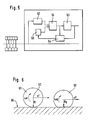
- FIG. 61 symbolizes a regular wheel on the road 60.
- the wheel center 63 moves with the vehicle chassis and thus with the vehicle speed vF on.
- the angular velocity ⁇ can be determined by means of wheel sensors, while the vehicle speed v as a rule can not be sensed.
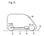
- Additional effects may affect the angular velocities of the wheels without the resulting difference between the angular velocities of individual wheels being an indication of pressure loss in one of the wheels. Examples include traction, different geometries when cornering, unbalanced load distribution in the vehicle and the like. Referring to FIGS. 1A to 1C, two effects are explained which result from the driving dynamics, in particular when cornering or when driving.
- FIG. 1A shows a vehicle 10 with wheel 11 at the front left, wheel 12 at the front right, wheel 13 at the rear right and wheel 14 at the rear left.
- the vehicle makes a turn to the right at speed vF, with the vehicle center of gravity S assumed following the radius R around the center point M.
- the wheels 12 and 13 on the right vehicle run on the inner track and therefore have a track with approximately the same, smaller inner radius Ri, while the wheels 11 and 14 run on the left side of the vehicle on the outer track and therefore drive a curve with the larger outer radius Ra. Since they thus have to travel a greater distance in the same time, the curve outer wheels 11 and 14 show a greater path speed and thus a greater angular velocity than the curve inner side wheels 12 and 13. However, these differences are not due to pressure loss in one of the wheels ,
- FIG. 1B Another effect will be explained with reference to FIG. 1B.
- the vehicle shown in Fig. 1A is shown here from behind, it follows the same path as the vehicle shown in Fig. 1A (curve to the right, so in Fig. 1B in the plane to the right) to the center M with radius R. Due to the cornering, there is a centrifugal force Fz, which acts on the vehicle center of gravity S. The counteracting force is the frictional force Fr between the vehicle wheels and the roadway. Since these forces do not act in the same plane, a rolling moment Mr results in the illustrated Situation counterclockwise about the longitudinal axis of the vehicle. This causes the curve outer side wheels 11 and 14 are more heavily loaded than the curve inner side wheels 12 and 13. They are thereby compressed more strongly, thus showing a smaller dynamic Abrollradius and thus a higher angular velocity.
- the effect of Fig. 1B is in the same direction as that described with reference to Fig. 1A, so that they add together.
- FIG. 1C shows a situation in which the vehicle 10 is moving on the road 15 driven by the engine 16.
- the rear axle so that the wheels 13, 14 may have both drive and brake slip, while the wheels of the front axle 11, 12 may have only brake slip.
- DE 19 721 480 A1 proposes a method in which wheel speeds are added in pairs, the sums are set in relation to each other and the quotient is checked for its value.
- a method is proposed in which the wheel speeds of the diagonally located wheels are added together and the resulting values are divided. This results in a quotient that deviates more or less from the ideal value of 1 (synchronization of all wheels).
- the ideal value of 1 synchronization of all wheels
- the object of the invention is to provide a method and a device for generating a correction value table, for determining a test variable and for detecting the pressure loss in a tire of a wheel, which allow a reliable detection of a pressure drop in a tire.
- a correction value table for a test variable for detecting a pressure loss in the tire of a vehicle In the method for generating a correction value table for a test variable for detecting a pressure loss in the tire of a vehicle, individual correction values for the test quantity are determined and stored as a function of the value of a vehicle dynamics quantity that prevailed during or at the time of correction value determination. Over time, this results in a table of correction values.
- the input quantity of the table is the vehicle dynamics quantity, the output value thus a driving dynamics-dependent correction value, so that the test quantity for Detection of a pressure loss in the tire of a vehicle can be corrected depending on the driving dynamics.
- Determining the correction value is a learning process.
- the correction value determination can take place when the vehicle dynamics, in particular the driving dynamics parameter, satisfy certain conditions with regard to their values or with regard to their time courses, be it absolute or relative. In particular, it may be required that the vehicle dynamics or, in particular, the mentioned driving dynamics parameter show a certain constancy (within a value range within a time window), or that the change in driving dynamics is less than a threshold value.
- the test quantity can be determined from several wheel radii or sizes that correspond to these wheel radii. For example, the test variable may be a quotient of two sums of two wheel radii each.
- the possible value range of the vehicle dynamics quantity can be divided into areas. With digital representation of the value of the driving dynamics parameter, the range division may already result from the digital quantization. Correction values can be determined as described above for one or more values of the vehicle dynamics quantity. For other values of the vehicle dynamics quantity, correction values can be determined by interpolation with suitable methods (linear, general polynomial).
- the driving dynamics variable may be a wheel torque and / or a curve characteristic.
- the test size can be determined from the sizes of several wheels of the vehicle. In particular, it can be the quotient of two sums of such quantities.
- Fig. 3 generally indicates the device for creating a correction value table. It receives sensor signals from sensors 31 and 32, wherein in Fig. 3 31 symbolize the four wheel sensors (one on each wheel), 32 other sensors such. Accelerometer, yaw rate sensor, steering angle sensor, transmission sensor, engine speed sensor and the like. As a rule, this will be digital data that has already undergone various processing steps (conversion, filtering, normalization). The data can be tapped from a vehicle data bus 37.
- the first determination device 33 symbolizes a first determination device for determining a vehicle dynamics quantity.
- the first determination device 33 can in particular receive the wheel signals and possibly further sensor signals or status variables from other control components and determine therefrom the vehicle dynamics quantity of the vehicle. For example, it can determine a wheel torque and / or a curve characteristic.
- the first determination device 33 also determines the value of the vehicle dynamics quantity as a digital quantity. Even this quantization, which results from the digitization, is followed by a range subdivision of the maximum possible value range of the vehicle dynamics quantity. The area division may be more or less coarse as desired. For a curve parameter, it may be sufficient to select three areas, namely left, straight, right. Of course, even finer graduations are possible.
- the driving dynamics parameter is the drive torque. This may be embodiments in which the method described only in the drive case (wheel torque greater than zero) is made, because then it can be assumed that the non-driven wheels roll freely.
- the method is applied in disengaged or non-powered and non-braking (wheel torque approximately 0) when all wheels roll freely.
- the second determination device 34 symbolizes a second determination device for determining a correction value and for storing it in a memory 35 as a function of the value of the vehicle dynamics quantity which prevailed during the correction value determination.
- the second determination device 34 can also receive the wheel signals as well as further sensor signals. It will make comparatively complex verification and investigation steps. It can receive the test variable to be corrected itself (symbolized by box 36).
- time profiles eg derivation, fluctuation within a time window
- the second determination device 34 finally determines a correction value for the test variable.
- the correction value is determined for a certain value of the vehicle dynamics quantity, so that it is usually required that during the determination of the correction value, the vehicle dynamics size remains within the considered value range or leaves it only briefly or only slightly.
- the correction value determination or storage preferably takes place only when the driving dynamics remained within a certain value range over a specific period of time.
- the (digital) value of the vehicle dynamics quantity can serve as the address of the memory location or be used for address determination. 38 symbolizes a data line for the correction value, 39 an address line on which the vehicle dynamics quantity is reflected.
- the individual entries in the table are determined as they are available.
- the setting of the driving dynamics parameter usually results from the state set by the driver.
- a correction value is determined, if the other conditions allow it.
- the determined correction value is then written to the corresponding table position.
- a table is built up over time.
- correction values can be extrapolated from determined correction values which apply to other values of the vehicle dynamics quantity, for example by linear or quadratic extrapolation. Extrapolated values can be overwritten later with determined values.
- ratios of curve characteristic to test variable are determined and stored.
- the correction value determination is a learning process, which is also ensured by the review of driving conditional conditions; that in the learned Correction value only the desired error size, but no other sizes.
- the memory 35 may be a volatile memory whose values are lost when the power is turned off (turning off the vehicle or removing its battery). But it may also be a non-volatile memory, so that the learned values in the memory 35 outlast an interruption of the power supply.
- the stored correction values serve to correct a test variable for the tire pressure.
- the test quantity may be such that it qualitatively provides an indication of the presence of a pressure loss at any of the vehicle wheels, but not yet a concrete indication of which wheel actually has the pressure loss.
- the test variable may be a variable whose value is determined from the wheel radii of at least two wheels. Instead of the wheel radii sizes can be used, which reflect these Radradien, such as the wheel speeds. There may be several qualitatively different test parameters, so that several different correction value tables would have to be created.
- the test variable may be a quotient of two sums, each sum being formed from the wheel radii of two of the four wheels of the vehicle.
- the sums contain pairs of different wheel radii.
- a sum can be formed from the wheel radii at the front of the vehicle, the other from the Radradien the rear of the vehicle.
- the quotient of these two sums forms a test variable for which, as described above, depending on the value of the vehicle dynamics quantity, correction values for establishing a correction value table whose input value is the value of the vehicle dynamics quantity are determined.
- a qualitatively different test quantity can be formed as the quotient of a sum of the wheel radii on the left side of the vehicle and a sum of the wheel radii on the right side of the vehicle.
- the vehicle dynamics quantity may be a wheel torque or a variable which was determined with reference to one or more wheel torques (for example average, maximum or minimum).
- a wheel torque may be determined by reference to, for example, a measured engine output torque and the ratio prevailing between the engine and the wheel.
- the engine torque can be derived from the indicated engine torque friction torque.
- the ratio can be determined from the engine speed and the wheel speed. A disengaged condition is considered accordingly.
- This information can be provided via a data bus, or this information can be obtained for reasons of plausibility.
- the friction torque of the engine and transmission can be taken into account.
- the driving dynamics quantity can also be a curve characteristic.
- the yaw rate angular velocity about the vertical axis, from sensor or detection device
- the curve radius in conjunction with the vehicle speed or the vehicle acceleration
- the steering angle in conjunction with the vehicle speed or the vehicle acceleration
- the lateral acceleration from sensor or Determination means.
- the curve characteristic can be determined from the wheel signals and / or from other sensor signals or detected signals.
- the curve characteristic can be generated redundantly.
- the curve characteristics determination may be arranged to operate primarily with respect to the wheel signals, but when, for example, a wheel signal is disturbed, the curve characteristics determination is made with respect to other signals. Insofar as the curve parameter is determined with reference to signals from a yaw rate sensor and / or acceleration sensor, care must be taken that reversing a vehicle does not lead to errors. If necessary, sign inversions are to be made.
- the creation of the correction value table can also be made dependent on general conditions. For example, it can be done at or after certain mileages. It can also take place at the driver's instigation. In general, conditions may be selected that prevent actual tire pressure losses from being learned as correction factors, which could result in the failure to detect tire pressure loss.
- the time course of the individual correction values can be tracked. If a correction value continuously changes in one direction within a certain period of time (for example within two hours) and / or within a certain driving distance (for example within 150 km), this can be an indication that an actual pressure loss has been wrongly learned as a correction value becomes. This can in turn lead to a warning.
- FIGS. 2A to 2C show ideal and real curves of different test parameters PG as a function of different driving dynamics variables, namely as a function of the curve characteristic KKG (FIGS. 2A and 2B) or as a function of the wheel torque RM (FIG. 2C).
- P G r 11 + r 13 r 12 + r 14
- the values of the diagonals were added together and the sums were charged to the quotient.
- FIG. 2B, left the different geometric relationships are canceled out so that a straight course through the point 1 on the ordinate would be expected.
- FIG. 2B shows an example on the right in FIG. 2B.
- the test variable does not run through the point 0/1 and can also have a certain slope here, again pointing out that a straight line does not necessarily have to reproduce the correct course of the test variable.
- P G r 11 + r 12 r 13 + r 14
- the test size determination device also has a second determination device 41 for determining a driving dynamics quantity. This is the driving dynamics parameter needed as input for the correction value table stored in memory 35.
- the second determination means 41 may be the same as the first determination means 33.
- a third determination device 42 determines the vehicle dynamics quantity in a conventional manner, for example by determining the size with reference to the wheel radii of a plurality of wheels. For this purpose, known methods can be used. The quotients described above can be formed from sums.
- a reading device 43 reads a correction value from the correction value table in the memory 35 in accordance with the driving dynamics variable determined in the second determination device 41.
- a correction device 44 corrects the value of the test variable determined by the second determination device 41.
- the correction value may be an additive value or a factor with which the determined value is added or multiplied. If the test quantity is the quotient of two "symmetric" sums, the ideal value is 1. A real value may deviate from that, for example, to 0.97. For example, by applying the correction value, the value of the test variable would be brought back to 1.00.
- Fig. 5 shows a device for detecting the pressure loss in a tire of a wheel.
- the detection device has a determination device 40 for determining a test variable for the tire pressure.
- the determining device can be designed as described above and in particular as shown schematically in FIG. 4. It determines a corrected test quantity, the test quantity being determined with reference to wheel radii of several wheels of the vehicle.
- the recognition device also has a comparison device 51, which compares the corrected test variable with one or more threshold values.
- a deviation still present after the correction would be an indication that either the numerator or the denominator of the fraction shows a changed value due to a pressure loss, so that the quotient also changes as a result. Since the change may be in the numerator or in the denominator, the test value may be checked for exceeding an upper threshold above the norm and below a lower threshold below the norm. The thresholds are symbolized by 55. Timing considerations can also be used in these threshold checks to prevent individual outliers in the corrected checklist from causing false positives.
- the test variable itself may also be subjected to processing, for example filtering or smoothing, for example by low-pass filtering or averaging over a time window.
- the temporal consideration in the threshold check, in a detection line direction 53, the verification may include whether the "stripping condition" lasts longer than a certain period of time or within a certain first period of time exceeds a certain smaller second period of time.
- test variable has reached or passed a threshold
- this check can not yet be deduced which wheel actually has the pressure loss. From the information as to whether either the upper threshold was exceeded or the lower threshold was exceeded, however, it can be deduced which pair of wheels has the pressure loss. If necessary, a qualitatively different test variable can then be used to determine the specific wheel at which a pressure loss exists.
- Both the correction value determination and the test size determination and the pressure loss detection can be speed-dependent.
- the vehicle speed can thus be another table input when the correction value table is created.
- the further method may then be such that, based on this assumption, the checking threshold values are changed by means of a changing device 54 so that the pressure loss detection is less sensitive. If then, preferably within a certain time or distance window, the changed threshold is again reached or passed, pressure loss is detected and a warning is issued.
- the test variable may be the quotient of the sum of the wheel radii at the front and the sum of the wheel radii at the rear.
- the thresholding may be such that on the driven axle the thresholds for other detection operations are modified differently than those on the non-driven axle. The modification can also take place as a function of the wheel torque and / or the gear stage of the vehicle.
Landscapes
- Engineering & Computer Science (AREA)
- Mechanical Engineering (AREA)
- Measuring Fluid Pressure (AREA)
Claims (15)
- Procédé pour établir un tableau de valeurs de correction pour une grandeur d'essai afin de détecter une perte de pression dans un pneu d'un véhicule, comportant les étapes suivantes :- déterminer une grandeur de la dynamique de conduite du véhicule, et- déterminer une valeur de correction pour la grandeur d'essai et mémoriser celle-ci en fonction de la valeur de la grandeur de la dynamique de conduite qui régnaitlors de la détermination de la valeur de correction, caractérisé en ce que la grandeur d'essai est déterminée à partir d'un quotient de deux sommes de chacune deux rayons de la roue ou grandeurs qui reflètent ces rayons de la roue.
- Procédé selon la revendication 1, caractérisé en ce que la détermination de la valeur de correction ne s'effectue que lorsque la dynamique du véhicule satisfait à des conditions déterminées en ce qui concerne ses valeurs et/ou variations dans le temps.
- Procédé selon la revendication 2, caractérisé en ce que la détermination de la valeur de correction ou sa mémorisation ne s'effectue que lorsque la dynamique de conduite est restée à l'intérieur d'une plage de valeurs déterminée pendant une durée déterminée.
- Procédé selon l'une des revendications précédentes,
caractérisé en ce qu'il est formé une somme se référant à des grandeurs des roues avant du véhicule et l'autre somme se référant à des grandeurs des roues arrière du véhicule. - Procédé selon l'une des revendications précédentes,
caractérisé en ce qu'il est formé une somme se référant à des grandeurs des roues sur le côté droit du véhicule et l'autre somme se référant à des grandeurs des roues sur le côté gauche du véhicule. - Procédé selon l'une des revendications précédentes,
caractérisé en ce qu'il est formé une somme se référant à des grandeurs des roues d'une diagonale du véhicule et l'autre somme se référant à des grandeurs des roues de l'autre diagonale du véhicule. - Procédé selon l'une des revendications précédentes,
caractérisé en ce qu'on détermine des valeurs de correction pour plusieurs valeurs de la grandeur de la dynamique de conduite et on extrapole des valeurs de correction à partir des valeurs de correction déterminées, pour d'autres valeurs de la grandeur de la dynamique de conduite. - Procédé selon l'une des revendications précédentes,
caractérisé en ce que la grandeur de la dynamique de conduite est un moment des roues qui est déterminé à partir du couple moteur et du rapport de transmission. - Procédé selon la revendication 8, caractérisé en ce que le rapport de transmission est déterminé à partir de la vitesse de rotation du moteur et de la vitesse des roues.
- Procédé selon l'une des revendications précédentes,
caractérisé en ce que la grandeur de la dynamique de conduite est une grandeur caractéristique de la courbe obtenue lors d'une conduite en courbe. - Procédé selon la revendication 10, caractérisé en ce qu'on peut utiliser comme grandeur caractéristique de la courbe une ou plusieurs des grandeurs suivantes :- l'embardée, également en combinaison avec la vitesse ou l'accélération du véhicule,- le rayon de la courbe en combinaison avec la vitesse du véhicule ou son accélération,- l'angle de braquage en combinaison avec la vitesse du véhicule ou son accélération,- l'accélération transversale, également en combinaison avec la vitesse ou l'accélération du véhicule.
- Procédé selon la revendication 11, caractérisé en ce que la mémorisation des valeurs de correction s'effectue en fonction de plusieurs grandeurs caractéristiques de la courbe.
- Procédé pour déterminer une grandeur d'essai corrigée afin de détecter une perte de pression dans les pneus d'un véhicule, comportant les étapes suivantes :- déterminer une grandeur d'essai à partir des rayons des roues ou à partir de grandeurs qui reflètent ces rayons des roues, au moins de deux roues,caractérisé par les étapes suivantes :- établir un tableau des valeurs de correction avec le procédé suivant l'une des revendications 1 à 12,- déterminer une grandeur de la dynamique de conduite du véhicule,- extraire une valeur de correction du tableau en fonction de la valeur de la grandeur de la dynamique de conduite, et- corriger la grandeur d'essai avec la valeur de correction.
- Procédé pour détecter la perte de pression du pneu d'une roue,
caractérisé par les étapes suivantes :- déterminer une grandeur d'essai pour détecter une perte de pression d'un pneu d'un véhicule avec le procédé selon la revendication 13,- comparer la grandeur d'essai à une valeur de seuil, et- reconnaître une perte de pression lorsque la grandeur d'essai atteint ou dépasse la valeur de seuil. - Procédé selon la revendication 14, caractérisé en ce que lorsque l'on suppose une perte de pression sur l'une des roues motrices, la valeur de seuil est modifiée de manière que la reconnaissance de la perte de pression soit plus sensible.
Applications Claiming Priority (7)
| Application Number | Priority Date | Filing Date | Title |
|---|---|---|---|
| DE19928138 | 1999-06-19 | ||
| DE19928137 | 1999-06-19 | ||
| DE19928137 | 1999-06-19 | ||
| DE19928138 | 1999-06-19 | ||
| DE19959554 | 1999-12-10 | ||
| DE19959554A DE19959554A1 (de) | 1999-06-19 | 1999-12-10 | Verfahrfen und Vorrichtung zur Erstellung einer Korrekturwerttabelle, zur Ermittlung einer Prüfgröße und zur Erkennung des Druckverlusts in einem Reifen eines Rades |
| PCT/EP2000/005033 WO2000078566A1 (fr) | 1999-06-19 | 2000-06-02 | Procede et dispositif pour elaborer une table de valeurs de correction, determiner une valeur d'essai et detecter une perte de pression dans un pneu de roue |
Publications (2)
| Publication Number | Publication Date |
|---|---|
| EP1194304A1 EP1194304A1 (fr) | 2002-04-10 |
| EP1194304B1 true EP1194304B1 (fr) | 2006-07-26 |
Family
ID=27219190
Family Applications (1)
| Application Number | Title | Priority Date | Filing Date |
|---|---|---|---|
| EP00936851A Expired - Lifetime EP1194304B1 (fr) | 1999-06-19 | 2000-06-02 | Procede et dispositif pour elaborer une table de valeurs de correction, determiner une valeur d'essai et detecter une perte de pression dans un pneu de roue |
Country Status (5)
| Country | Link |
|---|---|
| US (1) | US6817236B1 (fr) |
| EP (1) | EP1194304B1 (fr) |
| JP (1) | JP4660042B2 (fr) |
| DE (1) | DE50013236D1 (fr) |
| WO (1) | WO2000078566A1 (fr) |
Cited By (2)
| Publication number | Priority date | Publication date | Assignee | Title |
|---|---|---|---|---|
| DE102006020490A1 (de) * | 2006-02-24 | 2007-08-30 | Volkswagen Ag | Verfahren und Vorrichtung zur Umfangsermittlung von Fahrzeugrädern |
| DE102013004900A1 (de) | 2013-03-21 | 2014-09-25 | Valeo Schalter Und Sensoren Gmbh | Verfahren zum Bestimmen eines aktuellen Umfangs eines Rades eines Kraftfahrzeugs, Fahrerassistenzeinrichtung und Kraftfahrzeug |
Families Citing this family (7)
| Publication number | Priority date | Publication date | Assignee | Title |
|---|---|---|---|---|
| JP4744873B2 (ja) * | 2002-05-03 | 2011-08-10 | コンティネンタル・テーベス・アクチエンゲゼルシヤフト・ウント・コンパニー・オッフェネ・ハンデルスゲゼルシヤフト | 車輪回転数情報に基づいて直進走行を検出するための方法 |
| DE102005031485A1 (de) * | 2004-07-09 | 2006-02-23 | Continental Teves Ag & Co. Ohg | Verfahren zur Erkennung eines Druckverlusts in Kraftfahrzeugreifen |
| US8121758B2 (en) * | 2005-11-09 | 2012-02-21 | Ford Global Technologies | System for determining torque and tire forces using integrated sensing system |
| JP4796470B2 (ja) * | 2005-12-16 | 2011-10-19 | 住友ゴム工業株式会社 | タイヤ空気圧異常検出装置、方法およびプログラム |
| FR2927019B1 (fr) * | 2008-01-31 | 2010-02-19 | Renault Sas | Procede et systeme de diagnostic de l'etat de gonflage d'au moins un pneumatique d'un vehicule automobile |
| KR101339738B1 (ko) | 2011-12-26 | 2013-12-11 | 자동차부품연구원 | 타이어 감응형 차선유지지원장치 및 그 제어방법 |
| SE541908C2 (en) * | 2018-05-31 | 2020-01-07 | Scania Cv Ab | Method, Control Unit, Computer Program Product and Carrier for Identifying Low Tire Pressure in a Vehicle |
Family Cites Families (16)
| Publication number | Priority date | Publication date | Assignee | Title |
|---|---|---|---|---|
| GB9026558D0 (en) * | 1990-12-06 | 1991-01-23 | Sumitomo Rubber Ind | Method of detecting a deflated tyre on a vehicle |
| JPH04283665A (ja) * | 1991-03-12 | 1992-10-08 | Sumitomo Electric Ind Ltd | 車輪速度補正装置 |
| DE4228894A1 (de) * | 1992-08-29 | 1994-03-03 | Bosch Gmbh Robert | Verfahren und Vorrichtung zur Auswertung von Raddrehzahlsignalen bei einem Kraftfahrzeug |
| JPH0692118A (ja) * | 1992-09-16 | 1994-04-05 | Sumitomo Electric Ind Ltd | タイヤ空気圧低下検出装置 |
| US5826210A (en) | 1993-03-29 | 1998-10-20 | Mazda Motor Corporation | Tire air pressure warining device |
| DE4426734A1 (de) | 1993-08-20 | 1995-02-23 | Volkswagen Ag | Verfahren zum Erzeugen eines Reifendruck-Warnsignals |
| JP2746338B2 (ja) * | 1993-09-30 | 1998-05-06 | 本田技研工業株式会社 | タイヤ空気圧判定装置 |
| DE4337443A1 (de) * | 1993-11-03 | 1995-05-04 | Teves Gmbh Alfred | Verfahren und Schaltungsanordnung zur Reifendrucküberwachung |
| JP3286437B2 (ja) * | 1993-11-19 | 2002-05-27 | マツダ株式会社 | タイヤ空気圧判定装置 |
| JP3363553B2 (ja) * | 1993-12-14 | 2003-01-08 | 住友電気工業株式会社 | タイヤ空気圧低下検出装置 |
| JP2749784B2 (ja) * | 1994-11-21 | 1998-05-13 | 住友電気工業株式会社 | 旋回半径計算方法および旋回半径計算装置 |
| JPH08164720A (ja) * | 1994-12-15 | 1996-06-25 | Sumitomo Electric Ind Ltd | タイヤ空気圧低下検出方法およびタイヤ空気圧低下検出装置 |
| US5900543A (en) * | 1996-04-15 | 1999-05-04 | Sumitomo Rubber Industries, Ltd | Method for detecting decrease of tire air pressure and apparatus used therefor |
| JP3574541B2 (ja) * | 1997-01-07 | 2004-10-06 | トヨタ自動車株式会社 | タイヤ空気圧異常判定装置 |
| JPH10297228A (ja) * | 1997-04-25 | 1998-11-10 | Yokohama Rubber Co Ltd:The | タイヤ空気圧警報装置 |
| DE19721480A1 (de) | 1997-05-23 | 1998-11-26 | Itt Mfg Enterprises Inc | Verfahren zur Erkennung von Druckverlusten im Fahrzeugreifen |
-
2000
- 2000-06-02 JP JP2001504750A patent/JP4660042B2/ja not_active Expired - Fee Related
- 2000-06-02 EP EP00936851A patent/EP1194304B1/fr not_active Expired - Lifetime
- 2000-06-02 US US10/019,210 patent/US6817236B1/en not_active Expired - Fee Related
- 2000-06-02 DE DE50013236T patent/DE50013236D1/de not_active Expired - Lifetime
- 2000-06-02 WO PCT/EP2000/005033 patent/WO2000078566A1/fr active IP Right Grant
Cited By (3)
| Publication number | Priority date | Publication date | Assignee | Title |
|---|---|---|---|---|
| DE102006020490A1 (de) * | 2006-02-24 | 2007-08-30 | Volkswagen Ag | Verfahren und Vorrichtung zur Umfangsermittlung von Fahrzeugrädern |
| DE102013004900A1 (de) | 2013-03-21 | 2014-09-25 | Valeo Schalter Und Sensoren Gmbh | Verfahren zum Bestimmen eines aktuellen Umfangs eines Rades eines Kraftfahrzeugs, Fahrerassistenzeinrichtung und Kraftfahrzeug |
| WO2014146821A1 (fr) | 2013-03-21 | 2014-09-25 | Valeo Schalter Und Sensoren Gmbh | Procédé permettant de déterminer la portée actuelle d'une roue d'un véhicule automobile, dispositif d'aide à la conduite et véhicule automobile |
Also Published As
| Publication number | Publication date |
|---|---|
| US6817236B1 (en) | 2004-11-16 |
| JP4660042B2 (ja) | 2011-03-30 |
| JP2003502213A (ja) | 2003-01-21 |
| DE50013236D1 (de) | 2006-09-07 |
| WO2000078566A1 (fr) | 2000-12-28 |
| EP1194304A1 (fr) | 2002-04-10 |
Similar Documents
| Publication | Publication Date | Title |
|---|---|---|
| EP1826099B1 (fr) | Procédé destiné à la détermination du rapport de direction d'un véhicule | |
| WO1999026811A1 (fr) | Procede et dispositif pour detecter la tendance au basculement d'un vehicule | |
| WO2000048883A1 (fr) | Systeme de capteurs a dispositif de surveillance, en particulier pour un systeme de programme electronique de stabilite pour vehicules | |
| EP1049612A1 (fr) | Procede et dispositif de determination de l'adherence et de la limite d'adherence de pneus de vehicules | |
| WO1997027091A1 (fr) | Procede de determination de grandeurs decrivant le comportement de roulement d'un vehicule | |
| EP1194304B1 (fr) | Procede et dispositif pour elaborer une table de valeurs de correction, determiner une valeur d'essai et detecter une perte de pression dans un pneu de roue | |
| EP1206359B1 (fr) | Procede et dispositif pour la detection de la perte de pression dans le pneu d'une roue d'un vehicule automobile | |
| DE19521411A1 (de) | Verfahren und Anordnung zur Bestimmung der Geschwindigkeit eines Fahrzeuges | |
| EP1255653B1 (fr) | Procede et dispositif de detection d'une perte de pression sur les pneumatiques d'un vehicule, avec controle de plausibilite | |
| EP1765608B1 (fr) | Procede pour identifier une perte de pression dans des pneus de vehicule automobile | |
| EP1070007B1 (fr) | Procede et dispositif pour determiner des valeurs de correction pour des vitesses de roue | |
| DE19959554A1 (de) | Verfahrfen und Vorrichtung zur Erstellung einer Korrekturwerttabelle, zur Ermittlung einer Prüfgröße und zur Erkennung des Druckverlusts in einem Reifen eines Rades | |
| EP1240037A1 (fr) | Procede et dispositif permettant de detecter une perte de pression affectant des pneus d'automobile | |
| EP1240038B1 (fr) | Procede et dispositif permettant de detecter une perte de pression dans les pneus d'un vehicule a moteur | |
| DE102021130866A1 (de) | Verfahren zum Ermitteln einer Fahrzeugmasse eines Fahrzeuges, Massen-Abschätzungseinheit sowie Fahrzeug | |
| DE10260199A1 (de) | Detektionsverfahren für eine Sperrdifferentialeinrichtung, Verfahren und Vorrichtung zum Detektieren einer Reifenluftdruckabnahme unter Verwendung des Detektionsverfahrens und Programm zum Beurteilen eines Druckverlustes eines Reifens | |
| WO2017202417A1 (fr) | Procédé d'identification d'un rapport dans une boîte de vitesses mécanique de véhicules munis d'un embrayage à friction | |
| DE10044114A1 (de) | Verfahren und Vorrichtung zur Erkennung eines Druckverlustes von Reifen in Kraftfahrzeugen mit Plausibilitätsprüfung | |
| DE10050198A1 (de) | Verfahren und Vorrichtung zur Erkennung eines Druckverlustes von Reifen in Kraftfahrzeugen | |
| DE10300330B4 (de) | Verfahren zur Erkennung eines Reifendruckverlusts | |
| DE102020130913A1 (de) | Verfahren zum ermitteln einer fahrzeuggeschwindigkeit, computerprogrammprodukt, fahrassistenzsystem und fahrzeug | |
| DE19832483A1 (de) | Verfahren und Vorrichtung zum Ermitteln von Korrekturwerten für Radgeschwindigkeiten | |
| DE19500837C2 (de) | Raddrehzahlbedingter Bremskraftverteiler | |
| DE10343247A1 (de) | Verfahren zur Erkennung einer µ-Split-Situation | |
| DE10153850B4 (de) | Verfahren zur Verbesserung des Lernens von Korrekturfaktoren für Radgeschwindigkeiten |
Legal Events
| Date | Code | Title | Description |
|---|---|---|---|
| PUAI | Public reference made under article 153(3) epc to a published international application that has entered the european phase |
Free format text: ORIGINAL CODE: 0009012 |
|
| 17P | Request for examination filed |
Effective date: 20020121 |
|
| AK | Designated contracting states |
Kind code of ref document: A1 Designated state(s): AT BE CH CY DE DK ES FI FR GB GR IE IT LI LU MC NL PT SE |
|
| RBV | Designated contracting states (corrected) |
Designated state(s): DE FR |
|
| 17Q | First examination report despatched |
Effective date: 20040608 |
|
| GRAP | Despatch of communication of intention to grant a patent |
Free format text: ORIGINAL CODE: EPIDOSNIGR1 |
|
| GRAS | Grant fee paid |
Free format text: ORIGINAL CODE: EPIDOSNIGR3 |
|
| GRAA | (expected) grant |
Free format text: ORIGINAL CODE: 0009210 |
|
| AK | Designated contracting states |
Kind code of ref document: B1 Designated state(s): DE FR |
|
| REF | Corresponds to: |
Ref document number: 50013236 Country of ref document: DE Date of ref document: 20060907 Kind code of ref document: P |
|
| ET | Fr: translation filed | ||
| PLBE | No opposition filed within time limit |
Free format text: ORIGINAL CODE: 0009261 |
|
| STAA | Information on the status of an ep patent application or granted ep patent |
Free format text: STATUS: NO OPPOSITION FILED WITHIN TIME LIMIT |
|
| 26N | No opposition filed |
Effective date: 20070427 |
|
| PGFP | Annual fee paid to national office [announced via postgrant information from national office to epo] |
Ref country code: FR Payment date: 20140619 Year of fee payment: 15 |
|
| REG | Reference to a national code |
Ref country code: FR Ref legal event code: ST Effective date: 20160229 |
|
| PG25 | Lapsed in a contracting state [announced via postgrant information from national office to epo] |
Ref country code: FR Free format text: LAPSE BECAUSE OF NON-PAYMENT OF DUE FEES Effective date: 20150630 |
|
| PGFP | Annual fee paid to national office [announced via postgrant information from national office to epo] |
Ref country code: DE Payment date: 20180630 Year of fee payment: 19 |
|
| REG | Reference to a national code |
Ref country code: DE Ref legal event code: R119 Ref document number: 50013236 Country of ref document: DE |
|
| PG25 | Lapsed in a contracting state [announced via postgrant information from national office to epo] |
Ref country code: DE Free format text: LAPSE BECAUSE OF NON-PAYMENT OF DUE FEES Effective date: 20200101 |