EP1193432A2 - Ventil, insbesondere Heizkörperventil - Google Patents
Ventil, insbesondere Heizkörperventil Download PDFInfo
- Publication number
- EP1193432A2 EP1193432A2 EP01203474A EP01203474A EP1193432A2 EP 1193432 A2 EP1193432 A2 EP 1193432A2 EP 01203474 A EP01203474 A EP 01203474A EP 01203474 A EP01203474 A EP 01203474A EP 1193432 A2 EP1193432 A2 EP 1193432A2
- Authority
- EP
- European Patent Office
- Prior art keywords
- valve
- channel
- housing
- valve according
- seat
- Prior art date
- Legal status (The legal status is an assumption and is not a legal conclusion. Google has not performed a legal analysis and makes no representation as to the accuracy of the status listed.)
- Granted
Links
- XLYOFNOQVPJJNP-UHFFFAOYSA-N water Substances O XLYOFNOQVPJJNP-UHFFFAOYSA-N 0.000 description 19
- 239000007788 liquid Substances 0.000 description 2
- 238000007789 sealing Methods 0.000 description 2
- 230000015572 biosynthetic process Effects 0.000 description 1
- 230000002996 emotional effect Effects 0.000 description 1
- 238000010438 heat treatment Methods 0.000 description 1
- 239000008236 heating water Substances 0.000 description 1
- 238000009434 installation Methods 0.000 description 1
- 238000012797 qualification Methods 0.000 description 1
Images


Classifications
-
- F—MECHANICAL ENGINEERING; LIGHTING; HEATING; WEAPONS; BLASTING
- F24—HEATING; RANGES; VENTILATING
- F24D—DOMESTIC- OR SPACE-HEATING SYSTEMS, e.g. CENTRAL HEATING SYSTEMS; DOMESTIC HOT-WATER SUPPLY SYSTEMS; ELEMENTS OR COMPONENTS THEREFOR
- F24D19/00—Details
- F24D19/10—Arrangement or mounting of control or safety devices
- F24D19/1006—Arrangement or mounting of control or safety devices for water heating systems
- F24D19/1009—Arrangement or mounting of control or safety devices for water heating systems for central heating
- F24D19/1015—Arrangement or mounting of control or safety devices for water heating systems for central heating using a valve or valves
- F24D19/1018—Radiator valves
-
- F—MECHANICAL ENGINEERING; LIGHTING; HEATING; WEAPONS; BLASTING
- F16—ENGINEERING ELEMENTS AND UNITS; GENERAL MEASURES FOR PRODUCING AND MAINTAINING EFFECTIVE FUNCTIONING OF MACHINES OR INSTALLATIONS; THERMAL INSULATION IN GENERAL
- F16K—VALVES; TAPS; COCKS; ACTUATING-FLOATS; DEVICES FOR VENTING OR AERATING
- F16K11/00—Multiple-way valves, e.g. mixing valves; Pipe fittings incorporating such valves
- F16K11/10—Multiple-way valves, e.g. mixing valves; Pipe fittings incorporating such valves with two or more closure members not moving as a unit
- F16K11/20—Multiple-way valves, e.g. mixing valves; Pipe fittings incorporating such valves with two or more closure members not moving as a unit operated by separate actuating members
- F16K11/202—Multiple-way valves, e.g. mixing valves; Pipe fittings incorporating such valves with two or more closure members not moving as a unit operated by separate actuating members with concentric handles
-
- F—MECHANICAL ENGINEERING; LIGHTING; HEATING; WEAPONS; BLASTING
- F16—ENGINEERING ELEMENTS AND UNITS; GENERAL MEASURES FOR PRODUCING AND MAINTAINING EFFECTIVE FUNCTIONING OF MACHINES OR INSTALLATIONS; THERMAL INSULATION IN GENERAL
- F16K—VALVES; TAPS; COCKS; ACTUATING-FLOATS; DEVICES FOR VENTING OR AERATING
- F16K1/00—Lift valves or globe valves, i.e. cut-off apparatus with closure members having at least a component of their opening and closing motion perpendicular to the closing faces
- F16K1/32—Details
- F16K1/52—Means for additional adjustment of the rate of flow
-
- F—MECHANICAL ENGINEERING; LIGHTING; HEATING; WEAPONS; BLASTING
- F16—ENGINEERING ELEMENTS AND UNITS; GENERAL MEASURES FOR PRODUCING AND MAINTAINING EFFECTIVE FUNCTIONING OF MACHINES OR INSTALLATIONS; THERMAL INSULATION IN GENERAL
- F16K—VALVES; TAPS; COCKS; ACTUATING-FLOATS; DEVICES FOR VENTING OR AERATING
- F16K27/00—Construction of housing; Use of materials therefor
- F16K27/02—Construction of housing; Use of materials therefor of lift valves
Definitions
- the invention relates to a valve, in particular a radiator valve, with a valve housing that has an inlet port and has an outlet port, wherein one between the inlet port and the outlet port Shut-off device with a valve element and a Valve seat is arranged.
- Such a valve designed as a radiator valve is known from WO 99/22282.
- valve it looks different if the valve is connected incorrectly will, i.e. the feed line of a heating system is connected to the outlet port. In this case the water flows over the valve element to the valve seat and from there into the inlet connection. If the valve closes, the valve element is closed towards the valve seat emotional. If the gap between the valve element and the valve seat falls below a certain size, the valve element closes abruptly, which also sudden increase in pressure at the outlet connection Has. This increase in pressure manifests itself in a water hammer, which not only results in unpleasant noises has, but also cause damage to the pipe system can. This water hammer can also be caused by trigger an external pulse, for example through another valve that suddenly closes or opens, a pump that starts or stops, or other. These causes, which have not yet been fully clarified are particularly critical when the valve is incorrectly installed.
- the invention has for its object a valve to be able to operate independently of the flow direction.
- valve housing a Interior that has an inlet mouth with the Inlet connection and via an outlet mouth with the outlet connection communicates and that the valve seat at a first end of a channel within a seat housing is arranged, which is arranged in the interior and between a first position in which the second End of the canal with the inlet mouth covered stands, and a second position in the second end of the channel overlapping with the outlet mouth is rotatable, being between the valve housing and a free space is formed around a wall surrounding the channel is.
- the seat housing thus forms an insert in the valve housing, which can always be positioned so that the Flow direction through the valve is "correct". If the valve is connected so that the water flow via the input connector, then the seat housing positioned so that the water from the inlet port can enter the channel. Since the channel on Valve seat opens, the valve element is from the valve seat side Flown to the end. If the valve element is lifted off the valve seat, then the water can continue to flow through the space between the Valve housing and the seat housing is formed. The The outlet mouth is open in this case, so that the water can flow out through the outlet port. If that Valve is installed the other way around, so the water flows through the outlet port, then the seat housing simply twisted into the second position. The Water then comes through the outlet connection and the outlet mouth into the channel and the valve element flows again from the end on the valve seat side. The valve seat so remains stationary in the interior while the second end of the channel is swiveled to where that Water flows in.
- the seat housing can preferably be rotated about an axis, which are parallel to the direction of movement of the valve element runs. So the valve seat can not only be kept stationary in the interior, but he keeps also its orientation to the valve element. It therefore no new adjustment of the valve element is necessary, if the seat housing has been adjusted.
- the second end of the channel is one Seal surrounded. So that the inflowing water reliably separated from the escaping water. The Installation of a seal is possible with less effort than the highly precise adjustment of the seat housing and Valve body.
- the interior is preferably along a path, on which the second end of the channel moves, rotationally symmetrical educated.
- the second end of the channel therefore always remains at the same distance, preferably even in plant on the wall of the interior. In particular when using a seal, this ensures that the seal always stays in place. This makes it easier to adjust the seat housing.
- the interior preferably has at least one Area in which the inlet and outlet orifices are arranged are a spherical boundary wall.
- the Wall therefore forms part of a spherical surface. In order to can easily seal good options achieve.
- the first and second positions are preferred arranged at 180 ° to each other. This matches with the normal structure of the conventional radiator valve, at the inlet port and outlet port each other are opposite. This also makes hiring the desired angular position of the seat housing is simplified, because with a rotation of 180 ° you are independent always travel the same way from the direction of rotation got to.
- the inlet mouth preferably has an inlet axis and the outlet orifice has an outlet axis which both the same angle with the direction of movement of the Include valve element. This ensures that the second end of the channel regardless of the rotational position of the seat housing always a tight contact with the Achieve wall of the interior in the area of the mouths can.
- the angle is preferably in the range from 40 ° to 50 °. This configuration is particularly advantageous if when the inlet port is on the side and the outlet port is arranged at the bottom of the valve housing. In this Case arises at an angle of about 45 ° for both mouths approximately the same flow cross-section. Of course, there are other types of housing Angle possible.
- the seat housing preferably has a guide ring on that in the valve body or an associated Is led.
- the guide ring ensures that the seat housing that in the area of the second End of the channel is only on one side on the valve housing, always maintains the correct orientation so that the valve element with the necessary reliability can interact with the valve seat.
- a torque application surface is preferably on the guide ring arranged. Because the guide ring over his The circumference is supported practically uniformly Torque attack on the guide ring the best way to twist the seat housing evenly to avoid one-sided loads.
- the torque application surface preferably cooperates an adjustment device accessible from the outside.
- the guide ring does not have to be guided outwards become. Rather, one can use an adjustment device.
- Such an adjustment device is in many Valves already in place, for example, around one Presetting the flow rate.
- the guide ring is preferably with the valve seat connected via holder arms, the extension the holder arms in the circumferential direction at most exactly so is great, like the extension of gaps between the Holder arms. This ensures that the passing through the gap between valve seat and valve element Water has enough space to pass through the each not covered by the second end of the channel To flow the mouth out of the interior.
- the seat housing thus impedes the flow through the valve not yourself.
- a holding arm is preferably in the region in the circumferential direction the second end of the channel.
- the greatest forces occur through the inflowing water on, so that one holding arm has the necessary resistance here afford and plant the second end of the channel can hold on the wall of the interior.
- Two holding arms are preferably offset by 180 ° arranged to each other. This arrangement has two advantages. On the one hand is also on the incoming water opposite side always for a sufficient Support of the seat housing in the valve housing. On the other hand, two holder arms with accordingly large gaps between them only a relatively low resistance for the water flowing through the valve.
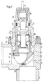
- Fig. 1 shows a radiator valve 1 with a valve housing 2, which has an inlet port 3 and an outlet port 4 has.
- inlet port and “Outlet port” are chosen here only to the two Differentiate connections. As explained below will be, it is not necessary that the water (or another liquid) actually through the Inlet port 3 in and through the outlet port 4th exit.
- An interior space 5 is arranged in the valve housing 2 via an inlet mouth 6 with the inlet connection 3 and an outlet mouth 7 connected to the outlet port 4 is.
- a seat housing 8 is arranged in the interior 5, in which runs a channel 9, the first end 10 and has a second end 11.
- the first end 10 of the channel 9 forms, as can be seen better from FIG. 2 is a valve seat 12 with which a valve element 13 interacts, which is known per se and therefore not actuated in more detail via a valve spindle 14 is in turn, again by a pin 15th is actuated, which is guided through a stuffing box 16 is.
- a spring 17 is shown schematically, which Valve element 13 pushes away from the valve seat 12.
- An O-ring surrounds the second end 11 of the channel 9.
- a groove 19 is provided on the seat housing 8 surrounds the second end 11 of the channel 9.
- FIG. 3 the Valve seat 12 via two holder arms 20, 21 with one Guide ring 22 connected.
- the guide ring 22 is how 1 and 2 can be seen in an insert 23 out, which is screwed into the valve housing 2 is.
- FIGS. 1 and 2 a small gap between the guide ring 22 and the Insert 23 provided. However, this gap is common smaller than shown, so that you have the seat housing 8 compared to the insert 23 and thus also opposite the valve body can twist without the position of the seat housing 8 in the valve housing 2 itself change.
- the one holder arm 20 (seen in the circumferential direction) attached to the valve seat 12 where the second end 11 of the channel 9 exits.
- the second bracket arm 21 is offset by 180 °.
- a torque application surface 24 is on the guide ring 22 provided, for example in the form of a slot. This torque application surface 24 can be supplemented around a corresponding torque application area, which around an angle deviating from 180 ° in the guide ring 22 is arranged.
- the torque application area 24 is definitely in the range of one of the two holder arms 20, 21.
- the extension of the two holder arms 20, 21 in the circumferential direction is at most the same size as in But generally much smaller than the extension of Gaps between the holder arms 20, 21 in the circumferential direction.
- the seat housing 8 is therefore very open, so that it the flow of water (or another liquid) practically no resistance.
- a outward adjustment element 25 in the insert 23 is arranged.
- This adjustment element 25 has one the insert 23 outstanding grip surface 26 on the a fitter either by hand or with a tool can attack the seat housing 8 in the valve housing 2 from the position shown in Fig. 1, in which the second end 11 of the channel 9 in register with the inlet mouth 6 stands to rotate by 180 °, so that second end 11 in register with the outlet mouth 7 stands.
- the shape of the bottom of the interior 5 corresponds to one Spherical surface, i.e. this surface is spherical.
- this surface is spherical.
- the seat housing 8 more specifically the the second end 11 of the channel 9 surrounding sealing surface 27 regardless of the angular position of the seat housing 8 opposite the valve housing 2 in contact with the wall of the Interior 5 is held.
- the spherical formation a good sealing possibility reached between the seat housing 8 and the valve housing 2, which is further improved by the O-ring 18. Since the seat housing 8 is not in any rotational position the valve housing 2 a larger gap between them both parts, there is no risk that the O-ring 18 can fall out of its groove 19.
- practically all can be rotationally symmetrical Shapes are used.
- valve element 13 On the holder arms 20, 21 there can additionally be projections 27 may be provided for guiding the valve element 13 are suitable. This ensures that regardless of the angular position of the seat housing 8th compared to the valve housing 2, the valve element 13 always is exactly aligned to the valve seat 12.
- inlet mouth 6 and the outlet mouth 7 are the inlet mouth 6 and the outlet mouth 7 by about 45 ° to the vertical, i.e. the direction of movement of the valve element 13 inclined.
- the inlet connection 3 is directed horizontally and the outlet port 4 vertical. Due to the orientation of the inlet mouth 6 and the outlet mouth 7 have both mouths in essentially the same cross section.
Landscapes
- Engineering & Computer Science (AREA)
- General Engineering & Computer Science (AREA)
- Mechanical Engineering (AREA)
- Combustion & Propulsion (AREA)
- Thermal Sciences (AREA)
- Chemical & Material Sciences (AREA)
- Physics & Mathematics (AREA)
- Taps Or Cocks (AREA)
- Lift Valve (AREA)
- Details Of Valves (AREA)
- Multiple-Way Valves (AREA)
- Valve Housings (AREA)
- Chair Legs, Seat Parts, And Backrests (AREA)
- Temperature-Responsive Valves (AREA)
Abstract
Description
- Fig. 1
- einen schematischen Querschnitt durch ein Heizkörperventil,
- Fig. 2
- einen vergrößerten Ausschnitt und
- Fig. 3
- eine perspektivische Ansicht eines Sitzgehäuses.
Claims (14)
- Ventil, insbesondere Heizkörperventil, mit einem Ventilgehäuse, das einen Einlaßanschluß und einen Auslaßanschluß aufweist, wobei zwischen dem Einlaßanschluß und dem Auslaßanschluß eine Absperreinrichtung mit einem Ventilelement und einem Ventilsitz angeordnet ist, dadurch gekennzeichnet, daß das Ventilgehäuse (2) einen Innenraum (5) aufweist, der über eine Einlaßmündung (6) mit dem Einlaßanschluß (3) und über eine Auslaßmündung (7) mit dem Auslaßanschluß (4) in Verbindung steht, und daß der Ventilsitz (12) an einem ersten Ende (10) eines Kanals (9) innerhalb eines Sitzgehäuses (8) angeordnet ist, das im Innenraum (5) angeordnet und zwischen einer ersten Position, in der das zweite Ende (11) des Kanals (9) mit der Einlaßmündung (6) in Überdeckung steht, und einer zweiten Position, in der das zweite Ende (11) des Kanals (9) mit der Auslaßmündung (7) in Überdeckung steht, verdrehbar ist, wobei zwischen dem Ventilgehäuse (2) und einer den Kanal (9) umgebenden Wand ein Freiraum ausgebildet ist.
- Ventil nach Anspruch 1, dadurch gekennzeichnet, daß das Sitzgehäuse (8) um eine Achse verdrehbar ist, die parallel zur Bewegungsrichtung des Ventilelements (13) verläuft.
- Ventil nach Anspruch 1 oder 2, dadurch gekennzeichnet, daß das zweite Ende (11) des Kanals (9) von einer Dichtung (18) umgeben ist.
- Ventil nach der Ansprüche 1 bis 3, dadurch gekennzeichnet, daß der Innenraum (5) entlang einer Bahn, auf der sich das zweite Ende (11) des Kanals (9) bewegt, rotationssymmetrisch ausgebildet ist.
- Ventil nach Anspruch 4, dadurch gekennzeichnet, daß der Innenraum (5) zumindest in einem Bereich, in dem die Einlaß- und Auslaßmündungen (6, 7) angeordnet sind, eine sphärische Begrenzungswand aufweist.
- Ventil nach einem der Ansprüche 1 bis 5, dadurch gekennzeichnet, daß die erste und die zweite Position um 180° versetzt zueinander angeordnet sind.
- Ventil nach einem der Ansprüche 1 bis 6, dadurch gekennzeichnet, daß die Einlaßmündung (6) eine Einlaßachse und die Auslaßmündung (7) eine Auslaßachse aufweist, die beide den gleichen Winkel mit der Bewegungsrichtung des Ventilelements (13) einschließen.
- Ventil nach Anspruch 7, dadurch gekennzeichnet, daß der Winkel im Bereich von 40° bis 50° liegt.
- Ventil nach einem der Ansprüche 1 bis 8, dadurch gekennzeichnet, daß das Sitzgehäuse (8) einen Führungsring (22) aufweist, der im Ventilgehäuse (2) oder einem damit verbundenen Einsatz (23) geführt ist.
- Ventil nach Anspruch 9, dadurch gekennzeichnet, daß eine Drehmomentangriffsfläche (24) im Führungsring (22) angeordnet ist.
- Ventil nach Anspruch 10, dadurch gekennzeichnet, daß die Drehmomentangriffsfläche (24) mit einer von außen zugänglichen Verstelleinrichtung (25) zusammenwirkt.
- Ventil nach einem der Ansprüche 9 bis 10, dadurch gekennzeichnet, daß der Führungsring (22) mit dem Ventilsitz (12) über Halterarme (20, 21) verbunden ist, wobei die Erstreckung der Halterarme (20, 21) in Umfangsrichtung höchstens genau so groß ist wie die Erstreckung von Lücken zwischen den Halterarmen (20, 21).
- Ventil nach Anspruch 12, dadurch gekennzeichnet, daß ein Halterarm (20) in Umfangsrichtung im Bereich des zweiten Endes (11) des Kanals (9) angeordnet ist.
- Ventil nach Anspruch 12 oder 13, dadurch gekennzeichnet, daß zwei Halterarme (20, 21) um 180° versetzt zueinander angeordnet sind.
Applications Claiming Priority (2)
| Application Number | Priority Date | Filing Date | Title |
|---|---|---|---|
| DE10048690 | 2000-09-30 | ||
| DE10048690A DE10048690B4 (de) | 2000-09-30 | 2000-09-30 | Ventil |
Publications (3)
| Publication Number | Publication Date |
|---|---|
| EP1193432A2 true EP1193432A2 (de) | 2002-04-03 |
| EP1193432A3 EP1193432A3 (de) | 2003-03-12 |
| EP1193432B1 EP1193432B1 (de) | 2006-05-24 |
Family
ID=7658358
Family Applications (1)
| Application Number | Title | Priority Date | Filing Date |
|---|---|---|---|
| EP01203474A Expired - Lifetime EP1193432B1 (de) | 2000-09-30 | 2001-09-14 | Ventil, insbesondere Heizkörperventil |
Country Status (10)
| Country | Link |
|---|---|
| EP (1) | EP1193432B1 (de) |
| CN (1) | CN1243920C (de) |
| AT (1) | ATE327458T1 (de) |
| BG (1) | BG105917A (de) |
| CZ (1) | CZ295495B6 (de) |
| DE (2) | DE10048690B4 (de) |
| ES (1) | ES2264960T3 (de) |
| PL (1) | PL198819B1 (de) |
| RU (1) | RU2209354C2 (de) |
| UA (1) | UA62020C2 (de) |
Cited By (7)
| Publication number | Priority date | Publication date | Assignee | Title |
|---|---|---|---|---|
| FR2861453A1 (fr) * | 2003-10-25 | 2005-04-29 | Danfoss As | Soupape integree pour un radiateur, notamment un radiateur multi-elements |
| WO2007095952A1 (de) * | 2006-02-24 | 2007-08-30 | Danfoss A/S | Ventil, insbesondere heizkörperventil, und einsatz für ein derartiges ventil |
| WO2008127208A1 (en) | 2007-04-13 | 2008-10-23 | Kalde Klima Orta Basinc Fittings Ve Valf Sanayi Anonim Sirketi | Plastic based radiator valve and the production method thereof |
| EP3193050A1 (de) | 2016-01-15 | 2017-07-19 | Danfoss A/S | Ventil, insbesondere wärmetauscherventil |
| EP3193049A1 (de) | 2016-01-15 | 2017-07-19 | Danfoss A/S | Ventil |
| EP3193062A1 (de) * | 2016-01-15 | 2017-07-19 | Danfoss A/S | Ventilanordnung und einsatz für eine ventilanordnung |
| EP3193058A1 (de) | 2016-01-15 | 2017-07-19 | Danfoss A/S | Ventil |
Families Citing this family (8)
| Publication number | Priority date | Publication date | Assignee | Title |
|---|---|---|---|---|
| US7896028B2 (en) * | 2006-08-04 | 2011-03-01 | Fisher Controls International Llc | Flow restricted seat ring for pressure regulators |
| FR2939486B1 (fr) * | 2008-12-09 | 2012-03-16 | Sames Technologies | Vanne pour la projection de produit de revetement et projecteur comportant une telle vanne |
| RU2409786C1 (ru) * | 2009-06-15 | 2011-01-20 | Общество с ограниченной ответственностью "Армтехстрой" | Биоболочковый корпус для трубопроводной арматуры |
| RU2498134C2 (ru) * | 2012-01-20 | 2013-11-10 | Данфосс А/С | Радиаторный клапан |
| CN102748505A (zh) * | 2012-07-13 | 2012-10-24 | 成都依瑞克科技有限公司 | 两通密封阀门 |
| CN102900869A (zh) * | 2012-07-13 | 2013-01-30 | 成都依瑞克科技有限公司 | 节流排出阀装置 |
| CN104613539B (zh) * | 2015-02-09 | 2017-03-29 | 张�浩 | 一种暖气片 |
| CN110220004A (zh) * | 2019-06-10 | 2019-09-10 | 江西艾芬达暖通科技股份有限公司 | 一种双流向温控阀体 |
Citations (1)
| Publication number | Priority date | Publication date | Assignee | Title |
|---|---|---|---|---|
| WO1999022282A1 (en) | 1997-10-23 | 1999-05-06 | Myson Heating Controls Limited | Flow control valves |
Family Cites Families (15)
| Publication number | Priority date | Publication date | Assignee | Title |
|---|---|---|---|---|
| DE24398C (de) * | G. SEIDEMAN in London | Neuerungen an Hähnen und Niederschraubventilen | ||
| FR902355A (fr) * | 1942-11-16 | 1945-08-29 | Vanne à tiroir ou à clapet | |
| DE1139707B (de) * | 1960-02-17 | 1962-11-15 | Regulation Automatique S A R L | Absperrhahn, insbesondere fuer Warmwasser- oder Dampfheizungsanlagen |
| DE1282379B (de) * | 1965-11-04 | 1968-11-07 | Danfoss As | Ventil |
| BE786715A (fr) * | 1971-07-27 | 1973-01-25 | Masco Corp | Clef de robinet |
| GB2067265A (en) * | 1980-01-10 | 1981-07-22 | Alexander Controls Ltd | Gas valves |
| FR2533656B3 (fr) * | 1982-09-23 | 1985-06-28 | Sdecc | Fourreau adaptateur pour transformation d'un robinet a commande manuelle en robinet a commande thermostatique |
| DE3300624C2 (de) * | 1983-01-11 | 1984-11-15 | Danfoss A/S, Nordborg | Ventil mit Voreinstellung der Durchflußmenge |
| DE3543330C1 (de) * | 1985-12-07 | 1986-10-09 | Honeywell-Braukmann GmbH, 6950 Mosbach | Thermostatventil |
| FR2611849B1 (fr) * | 1987-02-26 | 1989-06-09 | Comap | Dispositif de reglage interchangeable pour robinet thermostatique |
| JPH01299376A (ja) * | 1988-05-27 | 1989-12-04 | Hitachi Ltd | 玉型弁及び該玉型弁に用いるケーシングの製造方法並びに該玉型弁の修理方法及び修理治具 |
| DE9113745U1 (de) * | 1991-11-05 | 1992-01-16 | Becvar, Ivan, 6380 Bad Homburg | Thermostatisch regelbarer Heizkörperventil - Umbausatz |
| DE19512722C1 (de) * | 1995-04-05 | 1996-11-14 | Cgs Analysen Mess Und Regeltec | Pneumatikventil |
| DE19647028A1 (de) * | 1996-11-14 | 1998-05-28 | Danfoss As | Heizkörperventil |
| DE19813307B4 (de) * | 1998-03-26 | 2009-04-16 | Franz Schuck Gmbh | Absperrorgan mit einem Kugelhahn |
-
2000
- 2000-09-30 DE DE10048690A patent/DE10048690B4/de not_active Expired - Fee Related
-
2001
- 2001-09-11 UA UA2001096270A patent/UA62020C2/uk unknown
- 2001-09-14 ES ES01203474T patent/ES2264960T3/es not_active Expired - Lifetime
- 2001-09-14 DE DE50109858T patent/DE50109858D1/de not_active Expired - Lifetime
- 2001-09-14 EP EP01203474A patent/EP1193432B1/de not_active Expired - Lifetime
- 2001-09-14 AT AT01203474T patent/ATE327458T1/de not_active IP Right Cessation
- 2001-09-19 BG BG05917A patent/BG105917A/xx unknown
- 2001-09-21 CZ CZ20013397A patent/CZ295495B6/cs not_active IP Right Cessation
- 2001-09-26 RU RU2001126975/06A patent/RU2209354C2/ru not_active IP Right Cessation
- 2001-09-27 PL PL349903A patent/PL198819B1/pl unknown
- 2001-09-29 CN CNB011410507A patent/CN1243920C/zh not_active Expired - Fee Related
Patent Citations (1)
| Publication number | Priority date | Publication date | Assignee | Title |
|---|---|---|---|---|
| WO1999022282A1 (en) | 1997-10-23 | 1999-05-06 | Myson Heating Controls Limited | Flow control valves |
Cited By (17)
| Publication number | Priority date | Publication date | Assignee | Title |
|---|---|---|---|---|
| FR2861453A1 (fr) * | 2003-10-25 | 2005-04-29 | Danfoss As | Soupape integree pour un radiateur, notamment un radiateur multi-elements |
| WO2007095952A1 (de) * | 2006-02-24 | 2007-08-30 | Danfoss A/S | Ventil, insbesondere heizkörperventil, und einsatz für ein derartiges ventil |
| GB2448461A (en) * | 2006-02-24 | 2008-10-15 | Danfoss As | Valve in particular radiator valve and use of a valve of this type |
| RU2392523C1 (ru) * | 2006-02-24 | 2010-06-20 | Данфосс А/С | Клапан, в частности радиаторный клапан, и вставка для такого клапана |
| GB2448461B (en) * | 2006-02-24 | 2010-12-29 | Danfoss As | Valve |
| CN101389890B (zh) * | 2006-02-24 | 2012-07-18 | 丹佛斯公司 | 阀,尤其加热器阀和这种阀的插入件 |
| CZ305499B6 (cs) * | 2006-02-24 | 2015-11-04 | Danfoss A/S | Ventil, především ventil topného tělesa, a vložka pro takový ventil |
| WO2008127208A1 (en) | 2007-04-13 | 2008-10-23 | Kalde Klima Orta Basinc Fittings Ve Valf Sanayi Anonim Sirketi | Plastic based radiator valve and the production method thereof |
| EP3193050A1 (de) | 2016-01-15 | 2017-07-19 | Danfoss A/S | Ventil, insbesondere wärmetauscherventil |
| EP3193049A1 (de) | 2016-01-15 | 2017-07-19 | Danfoss A/S | Ventil |
| EP3193062A1 (de) * | 2016-01-15 | 2017-07-19 | Danfoss A/S | Ventilanordnung und einsatz für eine ventilanordnung |
| EP3193058A1 (de) | 2016-01-15 | 2017-07-19 | Danfoss A/S | Ventil |
| GB2546410A (en) * | 2016-01-15 | 2017-07-19 | Danfoss As | Valve, in particular valve heat exchanger valve |
| GB2546619A (en) * | 2016-01-15 | 2017-07-26 | Danfoss As | Valve |
| GB2546618A (en) * | 2016-01-15 | 2017-07-26 | Danfoss As | Valve |
| GB2546410B (en) * | 2016-01-15 | 2021-02-10 | Danfoss As | Valve, in particular valve heat exchanger valve |
| GB2546619B (en) * | 2016-01-15 | 2021-02-17 | Danfoss As | Valve |
Also Published As
| Publication number | Publication date |
|---|---|
| ES2264960T3 (es) | 2007-02-01 |
| DE10048690A1 (de) | 2002-04-25 |
| CZ20013397A3 (cs) | 2002-05-15 |
| DE10048690B4 (de) | 2006-04-13 |
| PL198819B1 (pl) | 2008-07-31 |
| UA62020C2 (en) | 2003-12-15 |
| EP1193432B1 (de) | 2006-05-24 |
| RU2209354C2 (ru) | 2003-07-27 |
| ATE327458T1 (de) | 2006-06-15 |
| PL349903A1 (en) | 2002-04-08 |
| CN1344871A (zh) | 2002-04-17 |
| DE50109858D1 (de) | 2006-06-29 |
| BG105917A (en) | 2002-09-30 |
| EP1193432A3 (de) | 2003-03-12 |
| CN1243920C (zh) | 2006-03-01 |
| CZ295495B6 (cs) | 2005-08-17 |
Similar Documents
| Publication | Publication Date | Title |
|---|---|---|
| EP0271765B1 (de) | Eigenmediumgesteuertes, durch ein vorzugsweise elektromagnetisch betätigtes Steuerventil auslösbares Ventil | |
| EP1193432B1 (de) | Ventil, insbesondere Heizkörperventil | |
| EP0122323B1 (de) | Doppelsitzventil mit zwei Ventiltellern | |
| EP0043076B1 (de) | Mischventil für Flüssigkeiten | |
| DE2311840C2 (de) | Mischventil für zwei Fluidströmungen | |
| DE2307025B2 (de) | Ventil zum Abdichten eines Abgasleitungsstücks | |
| DE60008954T2 (de) | Sicherheitgasventilanordnung für einen Kochherd | |
| EP0401633A2 (de) | Rückspülbare Filterarmatur | |
| EP1193431B1 (de) | Ventil, insbesondere Heizkörperventil | |
| EP1213519B1 (de) | Ventil, insbesondere Heizkörperventil | |
| DE2012827C3 (de) | Ventilaufsatz | |
| DE4318837C2 (de) | Vorrichtung zum Auslösen und Unterbrechen des Wasserlaufs aus einer Wasseraustrittsöffnung | |
| DE4312067B4 (de) | Ventil | |
| AT500717B1 (de) | Ventil, insbesondere heizkörperventil | |
| DE4030104C2 (de) | Strangregulierventil | |
| EP0527313B1 (de) | Armatur für Wasserleitungen | |
| EP0256204B1 (de) | Membranventil | |
| DE3911747C2 (de) | ||
| DE4214295C2 (de) | Mischhahn für eine Heizungsanlage und Verfahren zur Herstellung desselben | |
| DE3221036C2 (de) | Vorrichtung zum Absperren und Belüften einer Rohrleitung | |
| DE3114044C2 (de) | Vorrichtung zum Absperren und Belüften einer Rohrleitung | |
| EP0337936A1 (de) | Hauswasserstation | |
| DE2850222A1 (de) | Drosselklappenventil | |
| CH662384A5 (de) | Vorrichtung zum absperren und belueften einer rohrleitung. | |
| DE3590222T1 (de) | Durchgangshahn |
Legal Events
| Date | Code | Title | Description |
|---|---|---|---|
| PUAI | Public reference made under article 153(3) epc to a published international application that has entered the european phase |
Free format text: ORIGINAL CODE: 0009012 |
|
| AK | Designated contracting states |
Kind code of ref document: A2 Designated state(s): AT BE CH CY DE DK ES FI FR GB GR IE IT LI LU MC NL PT SE TR |
|
| AX | Request for extension of the european patent |
Free format text: AL;LT;LV;MK;RO;SI |
|
| PUAL | Search report despatched |
Free format text: ORIGINAL CODE: 0009013 |
|
| AK | Designated contracting states |
Kind code of ref document: A3 Designated state(s): AT BE CH CY DE DK ES FI FR GB GR IE IT LI LU MC NL PT SE TR |
|
| AX | Request for extension of the european patent |
Extension state: AL LT LV MK RO SI |
|
| 17P | Request for examination filed |
Effective date: 20030404 |
|
| AKX | Designation fees paid |
Designated state(s): AT BE CH CY DE DK ES FI FR GB GR IE IT LI LU MC NL PT SE TR |
|
| 17Q | First examination report despatched |
Effective date: 20050317 |
|
| GRAP | Despatch of communication of intention to grant a patent |
Free format text: ORIGINAL CODE: EPIDOSNIGR1 |
|
| GRAC | Information related to communication of intention to grant a patent modified |
Free format text: ORIGINAL CODE: EPIDOSCIGR1 |
|
| GRAS | Grant fee paid |
Free format text: ORIGINAL CODE: EPIDOSNIGR3 |
|
| GRAA | (expected) grant |
Free format text: ORIGINAL CODE: 0009210 |
|
| AK | Designated contracting states |
Kind code of ref document: B1 Designated state(s): AT BE CH CY DE DK ES FI FR GB GR IE IT LI LU MC NL PT SE TR |
|
| PG25 | Lapsed in a contracting state [announced via postgrant information from national office to epo] |
Ref country code: NL Free format text: LAPSE BECAUSE OF FAILURE TO SUBMIT A TRANSLATION OF THE DESCRIPTION OR TO PAY THE FEE WITHIN THE PRESCRIBED TIME-LIMIT Effective date: 20060524 Ref country code: FI Free format text: LAPSE BECAUSE OF FAILURE TO SUBMIT A TRANSLATION OF THE DESCRIPTION OR TO PAY THE FEE WITHIN THE PRESCRIBED TIME-LIMIT Effective date: 20060524 Ref country code: IE Free format text: LAPSE BECAUSE OF FAILURE TO SUBMIT A TRANSLATION OF THE DESCRIPTION OR TO PAY THE FEE WITHIN THE PRESCRIBED TIME-LIMIT Effective date: 20060524 |
|
| REG | Reference to a national code |
Ref country code: GB Ref legal event code: FG4D Free format text: NOT ENGLISH |
|
| REG | Reference to a national code |
Ref country code: CH Ref legal event code: EP |
|
| REG | Reference to a national code |
Ref country code: IE Ref legal event code: FG4D Free format text: LANGUAGE OF EP DOCUMENT: GERMAN |
|
| REF | Corresponds to: |
Ref document number: 50109858 Country of ref document: DE Date of ref document: 20060629 Kind code of ref document: P |
|
| PG25 | Lapsed in a contracting state [announced via postgrant information from national office to epo] |
Ref country code: SE Free format text: LAPSE BECAUSE OF FAILURE TO SUBMIT A TRANSLATION OF THE DESCRIPTION OR TO PAY THE FEE WITHIN THE PRESCRIBED TIME-LIMIT Effective date: 20060824 Ref country code: DK Free format text: LAPSE BECAUSE OF FAILURE TO SUBMIT A TRANSLATION OF THE DESCRIPTION OR TO PAY THE FEE WITHIN THE PRESCRIBED TIME-LIMIT Effective date: 20060824 |
|
| GBT | Gb: translation of ep patent filed (gb section 77(6)(a)/1977) |
Effective date: 20060906 |
|
| PG25 | Lapsed in a contracting state [announced via postgrant information from national office to epo] |
Ref country code: MC Free format text: LAPSE BECAUSE OF NON-PAYMENT OF DUE FEES Effective date: 20060930 Ref country code: CH Free format text: LAPSE BECAUSE OF NON-PAYMENT OF DUE FEES Effective date: 20060930 Ref country code: BE Free format text: LAPSE BECAUSE OF NON-PAYMENT OF DUE FEES Effective date: 20060930 Ref country code: LI Free format text: LAPSE BECAUSE OF NON-PAYMENT OF DUE FEES Effective date: 20060930 |
|
| PG25 | Lapsed in a contracting state [announced via postgrant information from national office to epo] |
Ref country code: PT Free format text: LAPSE BECAUSE OF FAILURE TO SUBMIT A TRANSLATION OF THE DESCRIPTION OR TO PAY THE FEE WITHIN THE PRESCRIBED TIME-LIMIT Effective date: 20061024 |
|
| NLV1 | Nl: lapsed or annulled due to failure to fulfill the requirements of art. 29p and 29m of the patents act | ||
| REG | Reference to a national code |
Ref country code: IE Ref legal event code: FD4D |
|
| ET | Fr: translation filed | ||
| REG | Reference to a national code |
Ref country code: ES Ref legal event code: FG2A Ref document number: 2264960 Country of ref document: ES Kind code of ref document: T3 |
|
| PLBE | No opposition filed within time limit |
Free format text: ORIGINAL CODE: 0009261 |
|
| STAA | Information on the status of an ep patent application or granted ep patent |
Free format text: STATUS: NO OPPOSITION FILED WITHIN TIME LIMIT |
|
| 26N | No opposition filed |
Effective date: 20070227 |
|
| REG | Reference to a national code |
Ref country code: CH Ref legal event code: PL |
|
| PG25 | Lapsed in a contracting state [announced via postgrant information from national office to epo] |
Ref country code: AT Free format text: LAPSE BECAUSE OF NON-PAYMENT OF DUE FEES Effective date: 20060914 |
|
| BERE | Be: lapsed |
Owner name: DANFOSS A/S Effective date: 20060930 |
|
| PG25 | Lapsed in a contracting state [announced via postgrant information from national office to epo] |
Ref country code: GR Free format text: LAPSE BECAUSE OF FAILURE TO SUBMIT A TRANSLATION OF THE DESCRIPTION OR TO PAY THE FEE WITHIN THE PRESCRIBED TIME-LIMIT Effective date: 20060825 |
|
| PG25 | Lapsed in a contracting state [announced via postgrant information from national office to epo] |
Ref country code: LU Free format text: LAPSE BECAUSE OF NON-PAYMENT OF DUE FEES Effective date: 20060914 |
|
| PG25 | Lapsed in a contracting state [announced via postgrant information from national office to epo] |
Ref country code: CY Free format text: LAPSE BECAUSE OF FAILURE TO SUBMIT A TRANSLATION OF THE DESCRIPTION OR TO PAY THE FEE WITHIN THE PRESCRIBED TIME-LIMIT Effective date: 20060524 |
|
| REG | Reference to a national code |
Ref country code: FR Ref legal event code: PLFP Year of fee payment: 15 |
|
| REG | Reference to a national code |
Ref country code: FR Ref legal event code: PLFP Year of fee payment: 16 |
|
| REG | Reference to a national code |
Ref country code: FR Ref legal event code: PLFP Year of fee payment: 17 |
|
| REG | Reference to a national code |
Ref country code: FR Ref legal event code: PLFP Year of fee payment: 18 |
|
| PGFP | Annual fee paid to national office [announced via postgrant information from national office to epo] |
Ref country code: IT Payment date: 20180919 Year of fee payment: 18 Ref country code: FR Payment date: 20180823 Year of fee payment: 18 Ref country code: DE Payment date: 20180904 Year of fee payment: 18 |
|
| REG | Reference to a national code |
Ref country code: DE Ref legal event code: R082 Ref document number: 50109858 Country of ref document: DE Representative=s name: KEIL & SCHAAFHAUSEN PATENTANWAELTE PARTGMBB, DE Ref country code: DE Ref legal event code: R082 Ref document number: 50109858 Country of ref document: DE Representative=s name: KEIL & SCHAAFHAUSEN PATENT- UND RECHTSANWAELTE, DE |
|
| PGFP | Annual fee paid to national office [announced via postgrant information from national office to epo] |
Ref country code: ES Payment date: 20181001 Year of fee payment: 18 |
|
| PGFP | Annual fee paid to national office [announced via postgrant information from national office to epo] |
Ref country code: TR Payment date: 20150914 Year of fee payment: 15 |
|
| REG | Reference to a national code |
Ref country code: DE Ref legal event code: R119 Ref document number: 50109858 Country of ref document: DE |
|
| PG25 | Lapsed in a contracting state [announced via postgrant information from national office to epo] |
Ref country code: DE Free format text: LAPSE BECAUSE OF NON-PAYMENT OF DUE FEES Effective date: 20200401 |
|
| PG25 | Lapsed in a contracting state [announced via postgrant information from national office to epo] |
Ref country code: IT Free format text: LAPSE BECAUSE OF NON-PAYMENT OF DUE FEES Effective date: 20190914 |
|
| PG25 | Lapsed in a contracting state [announced via postgrant information from national office to epo] |
Ref country code: FR Free format text: LAPSE BECAUSE OF NON-PAYMENT OF DUE FEES Effective date: 20190930 |
|
| PGFP | Annual fee paid to national office [announced via postgrant information from national office to epo] |
Ref country code: GB Payment date: 20200902 Year of fee payment: 20 |
|
| REG | Reference to a national code |
Ref country code: ES Ref legal event code: FD2A Effective date: 20210128 |
|
| PG25 | Lapsed in a contracting state [announced via postgrant information from national office to epo] |
Ref country code: ES Free format text: LAPSE BECAUSE OF NON-PAYMENT OF DUE FEES Effective date: 20190915 |
|
| REG | Reference to a national code |
Ref country code: GB Ref legal event code: PE20 Expiry date: 20210913 |
|
| PG25 | Lapsed in a contracting state [announced via postgrant information from national office to epo] |
Ref country code: GB Free format text: LAPSE BECAUSE OF EXPIRATION OF PROTECTION Effective date: 20210913 |
|
| PG25 | Lapsed in a contracting state [announced via postgrant information from national office to epo] |
Ref country code: TR Free format text: LAPSE BECAUSE OF NON-PAYMENT OF DUE FEES Effective date: 20190914 |