EP1192234B1 - Verfahren und vorrichtung zur pyrolyse und vergasung von organischen stoffen oder stoffgemischen - Google Patents
Verfahren und vorrichtung zur pyrolyse und vergasung von organischen stoffen oder stoffgemischen Download PDFInfo
- Publication number
- EP1192234B1 EP1192234B1 EP00954424A EP00954424A EP1192234B1 EP 1192234 B1 EP1192234 B1 EP 1192234B1 EP 00954424 A EP00954424 A EP 00954424A EP 00954424 A EP00954424 A EP 00954424A EP 1192234 B1 EP1192234 B1 EP 1192234B1
- Authority
- EP
- European Patent Office
- Prior art keywords
- pyrolysis
- bed
- fluidized
- accordance
- reactor
- Prior art date
- Legal status (The legal status is an assumption and is not a legal conclusion. Google has not performed a legal analysis and makes no representation as to the accuracy of the status listed.)
- Expired - Lifetime
Links
Images


Classifications
-
- F—MECHANICAL ENGINEERING; LIGHTING; HEATING; WEAPONS; BLASTING
- F23—COMBUSTION APPARATUS; COMBUSTION PROCESSES
- F23G—CREMATION FURNACES; CONSUMING WASTE PRODUCTS BY COMBUSTION
- F23G5/00—Incineration of waste; Incinerator constructions; Details, accessories or control therefor
- F23G5/02—Incineration of waste; Incinerator constructions; Details, accessories or control therefor with pretreatment
- F23G5/027—Incineration of waste; Incinerator constructions; Details, accessories or control therefor with pretreatment pyrolising or gasifying stage
- F23G5/0276—Incineration of waste; Incinerator constructions; Details, accessories or control therefor with pretreatment pyrolising or gasifying stage using direct heating
-
- C—CHEMISTRY; METALLURGY
- C10—PETROLEUM, GAS OR COKE INDUSTRIES; TECHNICAL GASES CONTAINING CARBON MONOXIDE; FUELS; LUBRICANTS; PEAT
- C10B—DESTRUCTIVE DISTILLATION OF CARBONACEOUS MATERIALS FOR PRODUCTION OF GAS, COKE, TAR, OR SIMILAR MATERIALS
- C10B49/00—Destructive distillation of solid carbonaceous materials by direct heating with heat-carrying agents including the partial combustion of the solid material to be treated
- C10B49/16—Destructive distillation of solid carbonaceous materials by direct heating with heat-carrying agents including the partial combustion of the solid material to be treated with moving solid heat-carriers in divided form
-
- C—CHEMISTRY; METALLURGY
- C10—PETROLEUM, GAS OR COKE INDUSTRIES; TECHNICAL GASES CONTAINING CARBON MONOXIDE; FUELS; LUBRICANTS; PEAT
- C10B—DESTRUCTIVE DISTILLATION OF CARBONACEOUS MATERIALS FOR PRODUCTION OF GAS, COKE, TAR, OR SIMILAR MATERIALS
- C10B49/00—Destructive distillation of solid carbonaceous materials by direct heating with heat-carrying agents including the partial combustion of the solid material to be treated
- C10B49/16—Destructive distillation of solid carbonaceous materials by direct heating with heat-carrying agents including the partial combustion of the solid material to be treated with moving solid heat-carriers in divided form
- C10B49/20—Destructive distillation of solid carbonaceous materials by direct heating with heat-carrying agents including the partial combustion of the solid material to be treated with moving solid heat-carriers in divided form in dispersed form
- C10B49/22—Destructive distillation of solid carbonaceous materials by direct heating with heat-carrying agents including the partial combustion of the solid material to be treated with moving solid heat-carriers in divided form in dispersed form according to the "fluidised bed" technique
-
- C—CHEMISTRY; METALLURGY
- C10—PETROLEUM, GAS OR COKE INDUSTRIES; TECHNICAL GASES CONTAINING CARBON MONOXIDE; FUELS; LUBRICANTS; PEAT
- C10B—DESTRUCTIVE DISTILLATION OF CARBONACEOUS MATERIALS FOR PRODUCTION OF GAS, COKE, TAR, OR SIMILAR MATERIALS
- C10B57/00—Other carbonising or coking processes; Features of destructive distillation processes in general
- C10B57/18—Modifying the properties of the distillation gases in the oven
-
- C—CHEMISTRY; METALLURGY
- C10—PETROLEUM, GAS OR COKE INDUSTRIES; TECHNICAL GASES CONTAINING CARBON MONOXIDE; FUELS; LUBRICANTS; PEAT
- C10K—PURIFYING OR MODIFYING THE CHEMICAL COMPOSITION OF COMBUSTIBLE GASES CONTAINING CARBON MONOXIDE
- C10K3/00—Modifying the chemical composition of combustible gases containing carbon monoxide to produce an improved fuel, e.g. one of different calorific value, which may be free from carbon monoxide
- C10K3/02—Modifying the chemical composition of combustible gases containing carbon monoxide to produce an improved fuel, e.g. one of different calorific value, which may be free from carbon monoxide by catalytic treatment
- C10K3/023—Reducing the tar content
-
- F—MECHANICAL ENGINEERING; LIGHTING; HEATING; WEAPONS; BLASTING
- F23—COMBUSTION APPARATUS; COMBUSTION PROCESSES
- F23G—CREMATION FURNACES; CONSUMING WASTE PRODUCTS BY COMBUSTION
- F23G5/00—Incineration of waste; Incinerator constructions; Details, accessories or control therefor
- F23G5/08—Incineration of waste; Incinerator constructions; Details, accessories or control therefor having supplementary heating
- F23G5/14—Incineration of waste; Incinerator constructions; Details, accessories or control therefor having supplementary heating including secondary combustion
- F23G5/16—Incineration of waste; Incinerator constructions; Details, accessories or control therefor having supplementary heating including secondary combustion in a separate combustion chamber
-
- F—MECHANICAL ENGINEERING; LIGHTING; HEATING; WEAPONS; BLASTING
- F23—COMBUSTION APPARATUS; COMBUSTION PROCESSES
- F23G—CREMATION FURNACES; CONSUMING WASTE PRODUCTS BY COMBUSTION
- F23G5/00—Incineration of waste; Incinerator constructions; Details, accessories or control therefor
- F23G5/30—Incineration of waste; Incinerator constructions; Details, accessories or control therefor having a fluidised bed
-
- Y—GENERAL TAGGING OF NEW TECHNOLOGICAL DEVELOPMENTS; GENERAL TAGGING OF CROSS-SECTIONAL TECHNOLOGIES SPANNING OVER SEVERAL SECTIONS OF THE IPC; TECHNICAL SUBJECTS COVERED BY FORMER USPC CROSS-REFERENCE ART COLLECTIONS [XRACs] AND DIGESTS
- Y02—TECHNOLOGIES OR APPLICATIONS FOR MITIGATION OR ADAPTATION AGAINST CLIMATE CHANGE
- Y02E—REDUCTION OF GREENHOUSE GAS [GHG] EMISSIONS, RELATED TO ENERGY GENERATION, TRANSMISSION OR DISTRIBUTION
- Y02E50/00—Technologies for the production of fuel of non-fossil origin
- Y02E50/10—Biofuels, e.g. bio-diesel
Definitions
- the invention relates to a process for the pyrolysis and gasification of organic substances or mixtures of substances and to an apparatus for carrying out such a process.
- the WO 99/31197 discloses a method and apparatus for gasification of organic matter in which the organics are contacted and pyrolyzed in a pyrolysis reactor with hot, recirculated from a furnace heat transfer material.
- the solid pyrolysis residues are transferred together with the heat transfer material into the furnace.
- the tarry pyrolysis gases are converted in a second reaction zone to a product gas with a high calorific value.
- the reaction to the product gas is carried out in an indirect heat exchanger, optionally with the addition of a reagent, wherein the heat content of the Feuerungsabgase is exploited for the chemical reaction.
- the combustion is carried out in a grate firing.
- a process in which the pyrolysis and the combustion of the solid carbonaceous residue are carried out in a fluidized bed is referred to as very expensive and rejected.
- the invention has for its object to provide a simple method to be performed for the pyrolysis and gasification of organic substances or mixtures and a device for producing a gas with a high calorific value available put.
- this object is achieved according to the invention in that the pyrolysis is carried out in a moving bed reactor or a rotary tube reactor, the pyrolysis gases optionally a reaction agent, e.g. Water vapor and / or oxygen is added, and they are passed into a reaction zone in which the pyrolysis react with the reactant.
- the solid carbonaceous residue and optionally a portion of the pyrolysis gas are fed to a fluidized bed combustion reactor alone or together with the fluidized bed material and burned there. As a result, the fluidized bed material is heated.
- the combustion exhaust gases and fluidized bed material are contacted with the reaction zone such that their heat content can be used for the reaction of the pyrolysis gases with the reactant.
- withdrawn fluidized bed material consisting of ash, unburned coke and optionally additionally supplied refractory fluidized bed material is recycled as a heat transfer medium to the pyrolysis reactor.
- the heat transfer to the feedstock to carry out the pyrolysis takes place by contact with the fluidized bed material and optionally additionally by the hot wall of the fluidized bed combustion reactor.
- the hot fluid bed material supplied to the pyrolysis reactor from the combustion fluidized bed causes rapid drying and pyrolysis of the feedstock by contact.
- reactor offers a shaft furnace, in which the mixture of the feedstock and the fluidized bed material migrates from top to bottom through the shaft furnace.
- conveyor coils or agitators can be provided.
- the pyrolysis reactor can be carried out, for example, as a rotary tube reactor, whereby a good mixing achieved by feedstock and hot fluidized bed material and at the same time the transport of solids is ensured.
- the water vapor escaping from the feed during drying and the pyrolysis gases leave the pyrolysis reactor and enter a further reaction zone.
- the mixture of the remaining solid carbonaceous pyrolysis residue and the fluidized bed material is conveyed together into the combustion fluidized bed, using conventional components such as screw conveyors or rotary valves with slanted tube entry.
- a screw is preferred.
- the pyrolysis is preferably carried out in a shaft furnace, it is possible to dispense with the supply of a fluidization medium necessary for a pyrolysis fluidized bed.
- This makes it possible to perform the pyrolysis completely waiving gas supply or, in contrast to a pyrolysis fluidized bed, which must be supplied for fluidizing a minimum amount of gas, any small amounts, for example, of the product gas or a reactant such as water vapor, oxygen or air admit.
- gas or a reagent to the pyrolysis reactor as a process engineering adaptation to the respective starting material.
- the pyrolysis in the pyrolysis reactor is preferably carried out with exclusion of air and gas.
- Another advantage of carrying out the pyrolysis in a separate process step is that the comminution effect occurring during the pyrolysis due to the carbonization and degassing allows the use of coarser lumpy, than usually used in fluidized bed reactors, Good.
- a comminuting device such as a roller crusher, thus further reducing the requirements for feedstock particle sizes.
- the applied for crushing of pyrolysis coke energy is much lower than that for comminution of eg biomass such as wood.
- the carbonaceous solid pyrolysis residue is burned in the fluidized bed with air, is thereby as ash itself to the fluidized bed material and heats up by the energy release already existing fluid bed material on and on again.
- the combustion fluidized bed can be designed and operated according to the knowledge of the fluidised bed technique. With regard to the emissions of the combustion fluidized bed, a gradual addition of air may be advantageous.
- the combustion reactor is designed as a stationary fluidized bed, that is, the amount of gas of the fluidized bed must be sufficient on the one hand to exceed the minimum fluidization rate of the solid and on the other hand must not exceed the speed for the discharge. From a fluidized bed height of about 2.5 m to 3 m internals to prevent the formation of a colliding fluidized bed and the associated pressure pulsations are required.
- the fluidized bed material heated by the combustion process is finally returned to the pyrolysis reactor.
- the fluidized bed material consists of the ash remaining from the combustion of the solid carbonaceous pyrolysis residue. If an incomplete combustion of the pyrolysis coke takes place within the combustion fluidized bed, the fluidized bed material, which is circulated as the heat transfer medium, consists of the ashes of the feedstock and unburned carbonaceous pyrolysis residue. Since the solid pyrolysis residues of the organic substances and substance mixtures generally react quickly in the combustion fluidized bed and may in some cases only have small proportions of non-gasifiable or combustible material, it may be necessary to add additional material to form a fluidized bed.
- the feedstocks carry large quantities of non-gas or combustible material suitable for the construction of a fluidized bed.
- the material to be added which serves to form a fluidized bed, all refractory materials, such as sand with a particle diameter smaller than 1.5 mm are suitable.
- the removal of the hot fluid bed material and the transport into the pyrolysis reactor is preferably accomplished by means of one or more overflows, which are provided on the reactor wall or project through the reactor wall in the fluidized bed.
- the method has the advantage that in addition to the transmission of the hot fluidized bed material in the pyrolysis reactor in a simple manner, the fluidized bed height of the combustion fluidized bed can be adjusted.
- the withdrawal of the fluidized bed material can also be carried out by means of other known delivery units, such as a screw conveyor, however, the process complexity is higher in this case.
- the invention is based on the basic idea to divide the process into process steps which are easy to carry out.
- the individual process stages and their interaction can be optimally designed taking into account the special properties of the starting material and with regard to the intended product gas quality to be achieved.
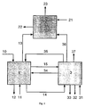
- FIG. 1 It can be seen that in the pyrolysis 1 feedstock 10 and fluidized bed material 35 is supplied as a heat transfer medium.
- the heat flow transported with the fluidized bed material 35 results from the temperature of the combustion fluidized bed, the nature and the mass flow of the fluidized bed material 35 and the feed stream 10 and from the desired pyrolysis temperature.
- a reaction medium 11 is supplied and a heat flow 34 is transferred from the combustion fluidized bed 3.
- the pyrolysis stage 1 leaves pyrolysis gas 13, which is fed into the reaction zone 2, pyrolysis gas 15, which is fed into the combustion reactor (to the combustion fluidized bed 3), a mixture of fluidized bed material and solid carbonaceous pyrolysis residue 14 and a heat loss stream 12th
- the mixture of fluidized bed material and solid carbonaceous pyrolysis residue 14 is fed into the combustion fluidized bed 3 together with pyrolysis gas 15 and air 31.
- the heated by the combustion fluidized bed material 35 is fed back into the pyrolysis reactor 1.
- the likewise hot exhaust gas 37 leaves the combustion fluidized bed 3.
- a portion of the heat contained in the exhaust gas 36 is transferred to the reaction zone 2.
- the combustion reactor 3 also leaves a heat loss stream 33 and fluidized bed material 32, which must be removed to regulate the total solids budget in steady state operation.
- reaction zone 2 supplied pyrolysis gas 13 is reacted together with the reagent 21 by means of the supplied heat 36 in the presence of a catalyst to the product gas 23.
- the product gas 23 and a heat loss stream 22 finally leave the reaction zone 2.
- the preferred method according to Fig. 2 and the preferred device according to Fig. 3 is used for pyrolysis and gasification of 900 kg of wood per hour.
- the wood used by way of example consists essentially of 52.3% by weight of carbon, 5.9% by weight of hydrogen and 41.8% by weight of oxygen, based in each case on the water- and ashless fuel substance and furthermore has an ash content of 0 , 51% by weight on the raw feedstock.
- FIG. 2 described preferred embodiment of the method for wood gasification wood 10 is subjected in a processing stage 4, depending on the nature of the feedstock crushing and / or drying, before it is added to the pyrolysis 1.
- the wood after the treatment stage 4 has a water content of 8.9 wt .-%.
- the pyrolysis is carried out at a temperature of 580 ° C.
- the introduced into the pyrolysis reactor 1 fluidized bed material 35 has a temperature of 900 ° C, so that in order to heat the feed to the pyrolysis of 580 ° C, the 4.1-fold amount of fluidized bed material, ie 3.7 t / h, fed and in Circulation must be.
- the 4.1-fold amount of fluidized bed material ie 3.7 t / h, fed and in Circulation must be.
- the remaining products from the drying and pyrolysis leave the pyrolysis reactor 1 as gas 13 and enter the reaction zone 2.
- the mixture of solid pyrolysis residue and fluidized bed material 14 is the combustion fluidized bed 3 and burned there with air 31 burned.
- the enthalpy flow supplied to the solid pyrolysis residue of the wood of the combustion fluidized bed is 1.52 MW.
- the pyrolysis gases 13 are passed under supply of the reaction medium water vapor 21 in the reaction zone 2, consisting of a heat exchanger, which is equipped with a catalyst for improving the Teercrackung.
- the energy required for the reaction of the pyrolysis gas 13 with the water vapor 21 is released via the hot flue gas stream 36 from the combustion fluidized bed 3 to the heat exchanger 2, wherein the reaction takes place depending on the operation of the combustion fluidized bed 3 at 850 ° C to 900 ° C.
- water or oxygen can also be added to the reactant water vapor 21.
- the product gas 23 obtained has a calorific value of 9.87 MJ / m 3 (V N ) and is composed of the following gas components: 48.7% by volume of H 2 , 36.1% by volume of CO, 0.1% by volume .-% CH 4 , 6.1 vol.% CO 2 , 9 vol .-% H 2 0.
- the product gas 23 is then dedusted and quenched in a treatment stage 5.
- the cold gas efficiency ie the chemical energy of the starting material, based on the chemical energy content of the product gas, is 80.8%.
- FIG. 3 shows by way of example sketched a preferred embodiment of the apparatus according to the invention for pyrolysis and gasification.
- the wood 10 is placed in the pyrolysis reactor 1 via a gas-tight entry device, in the case illustrated here by way of example, a rotary valve. Drying and pyrolysis of the feedstock takes place by contact with the hot fluidized bed material 35 fed through an overflow from the combustion fluidized bed 3.
- the resulting pyrolysis gas 13 is passed with the addition of water vapor 21 in the reaction zone 2, which is exemplified here as a tubular heat exchanger. After the reaction of the pyrolysis gas with the water vapor 21, the product gas 23 is cooled and purified in the treatment stage 5.
- the blower of the product gas line 50 and the fan of the flue gas line 60 are to be matched to one another. Characterized in that the overflow from the combustion fluidized bed 3 to the pyrolysis reactor 1 is designed so that it is constantly filled with fluidized bed material 35, in combination with said blowers, the exchange of gas between the two reactors to simple Way prevented.
- a screw is preferably provided to transport the mixture of solid pyrolysis residue and circulating fluidized bed material 14 into the combustion fluidized bed 3.
- the screw is to be designed such that the pressure loss through the material-filled screw flights is greater than over the fluidized bed 3, so that the air supplied to the combustion fluid layer 3 31 does not flow in bypass through the pyrolysis reactor 1.
- a steam flow 71 is generated via a heat exchanger 8 from a water flow 70, which steam is released, for example, via a turbine 9.
- a portion of the vapor stream 71 may be used as the water vapor 21 for the reaction zone 2.
- the exhaust gas 60 is supplied to a flue gas cleaning 6.
Landscapes
- Chemical & Material Sciences (AREA)
- Engineering & Computer Science (AREA)
- Oil, Petroleum & Natural Gas (AREA)
- Organic Chemistry (AREA)
- Combustion & Propulsion (AREA)
- Materials Engineering (AREA)
- Mechanical Engineering (AREA)
- Dispersion Chemistry (AREA)
- General Engineering & Computer Science (AREA)
- General Chemical & Material Sciences (AREA)
- Chemical Kinetics & Catalysis (AREA)
- Gasification And Melting Of Waste (AREA)
- Processing Of Solid Wastes (AREA)
- Coke Industry (AREA)
- Organic Low-Molecular-Weight Compounds And Preparation Thereof (AREA)
- Fluidized-Bed Combustion And Resonant Combustion (AREA)
- Incineration Of Waste (AREA)
- Acyclic And Carbocyclic Compounds In Medicinal Compositions (AREA)
Description
- Die Erfindung betrifft ein Verfahren zur Pyrolyse und Vergasung von organischen Stoffen oder Stoffgemischen und eine Vorrichtung zur Durchführung eines derartigen Verfahrens.
- Für die Behandlung und Nutzung organischer Stoffe und Stoffgemische durch zum Beispiel Vergasung und Pyrolyse sind eine Reihe von Verfahren bekannt. Die Verfahren unterscheiden sich nach dem verwendeten Oxidations- bzw. Reduktionsgas, sowie nach der Art des Kontaktes zwischen Feststoff und Gas. Nach der Feststoff- und Gasführung unterscheidet man unter anderem zirkulierende Wirbelschichtvergaser, Flugstromvergaser, Drehrohrvergaser und Wanderbettvergaser mit Gegenstrom-, Gleichstrom- oder Querstromgasführung. Die Mehrzahl der bekannten Vergasungsverfahren ist aufgrund des hohen apparativen Aufwandes nicht für kleinere, dezentrale Anlagen geeignet. Kleinere dezentrale Anlagen empfehlen sich insbesondere bei Verwendung des Einsatzstoffes Biomasse.
- Das Betriebsverhalten von Vergasungsverfahren nach dem Prinzip der zirkulierenden Wirbelschicht ist stark vom jeweiligen Korngrößenhaushalt der Wirbelschicht abhängig, bestehend aus dem zu vergasenden Einsatzstoff und dem ebenfalls zirkulierenden Inertmaterial. Daraus ergeben sich entsprechende Anforderungen an die Stückgröße des Einsatzmaterials. Noch weitaus höhere Anforderungen an die Aufbereitung des Brennstoffs ergeben sich im Fall der Flugstromvergasung, die lediglich den Einsatz feingemahlener Brennstoffkörner erlaubt.
- Weitere wesentliche Nachteile der bekannten Vergasungsverfahren bestehen darin, daß die ablaufenden Prozesschritte Trocknung, Entgasung, Vergasung und Verbrennung des Einsatzstoffes in unmittelbar nebeneinander liegenden Zonen, die ineinander übergehen, abläuft. Dadurch sind die einzelnen Zonen innerhalb eines Reaktors unbestimmt und Entgasung, Vergasung und Verbrennung können örtlich unvollständig ablaufen. In weiteren bekannten Verfahren wird versucht diese Nachteile durch die Trennung der einzelnen am Brennstoff ablaufenden Prozeßschritte Entgasung, Vergasung und Verbrennung aufzuheben.
- In der
DE 197 20 331 A1 werden ein Verfahren und eine Vorrichtung zur Vergasung oder Verbrennung von trockener oder feuchter, feinkörniger oder stückiger Biomasse sowie von Abfall vorgeschlagen, bei dem durch die heiße Wandung eines Verbrennungsofens und durch das Einströmen heißen Abgases aus dem Verbrennungsofen in einen Entgasungsofen biologische Rohstoffe in diesem entgasen, wodurch Koks und Pyrolysegas entstehen, wobei der Koks nach Passieren des Zerkleinerers auf das Glutbett des Vergasungsreaktors gelangt, während das Pyrolysegas im Verbrennungsraum des Vergasungsreaktors unter Zuführung einer begrenzten Luftmenge verbrennt und das entstehende Abgas nachfolgend durch das Glutbett des Vergasungsreaktors strömt, in dem eine Oxidation des Kohlenstoffs zu CO bei gleichzeitiger Reduktion von Abgas (CO2) und Wasserdampf (H2O) zu einem brennbarem Schwachgas (CO, H2) stattfindet. Dadurch, dass die Pyrolyse durch die Erwärmung aufgrund des Kontaktes mit heißen Verbrennungsabgasen durchgeführt wird und desweiteren eine Teilverbrennung des Pyrolysegases durchgeführt wird, ist mit dem in derDE 197 20 331 A1 vorgeschlagenen Verfahren lediglich ein Produktgas mit geringem Heizwert herzustellen. Bei Verwendung von Brennstoffen mit hohem Gehalt an flüchtigen Bestandteilen und geringer Pyrolysekoksausbeute besteht die Gefahr einer unzureichenden Ausbildung des aus Pyrolysekoks bestehenden Glutbetts des Vergasungsreaktors, wodurch die Oxidation des Kohlenstoffs zu CO bei gleichzeitiger Reduktion von Abgas und Wasserdampf zu einem brennbaren Schwachgas auf Kosten des Produktgasheizwertes unzureichend abläuft. - Aus der
US 4,568,362 ist weiterhin ein Verfahren zur Vergasung von organischen Stoffen und Stoffgemischen bekannt, bei dem die organischen Stoffe in einen Pyrolysereaktor geleitet werden, in dem die organischen Stoffe mit einem Wärmeträgermedium in Kontakt kommen, wodurch eine schnelle Pyrolyse stattfindet, die die organischen Stoffe in Pyrolyseprodukte umsetzt, die aus Pyrolysegasen mit kondensierbaren Stoffen und einem festen kohlenstoffhaltigen Rückstand bestehen und die nötige Wärmeenergie für die Pyrolyse durch Verbrennen des festen kohlenstoffhaltigen Rückstandes in einem Verbrennungsreaktor erzeugt wird und die teerhaltigen Pyrolysegase in einer zweiten Reaktionszone des Pyrolysereaktors derart Crackreaktionen und Reaktionen mit Wasserdampf unterworfen werden, dass ein Produktgas mit hohem Heizwert erhalten wird. Bei diesen Verfahren erfolgt sowohl die Pyrolyse, als auch die Verbrennung des festen kohlenstoffhaltigen Rückstands in einer Wirbelschicht. In dem oberen Teil der Pyrolysewirbelschicht ist eine Reaktionszone für die teerhaltigen Pyrolysegase vorgesehen. Das Betreiben der Wirbelschichten ist sehr aufwendig und eine Steuerung der Reaktionen der Pyrolysegase in der Reaktionszone ist kaum möglich. - Die
WO 99/31197 - Aus der
US-A-4 244 779 ist ein Verfahren und eine Vorrichtung für die thermische Zersetzung organischer Materialien bekannt, wobei das organische Material mit heißem rezirkuliertem Feststoff aus einer Verbrennungswirbelschicht in Kontakt gebracht und dabei pyrolysiert wird. Die festen Pyrolyseprodukte werden in die Verbrennungswirbelschicht überführt und verbrannt, die Pyrolysegase werden abgezogen und einer Gasreinigung unterworfen. - Der Erfindung liegt die Aufgabe zugrunde, ein einfach durchzuführendes Verfahren zur Pyrolyse und Vergasung von organischen Stoffen oder Stoffgemischen und eine Vorrichtung zur Erzeugung eines Gases mit hohem Heizwert zur Verfügung zu stellen. Diese Aufgaben werden durch die Merkmale der Patentansprüche 1 und 15 gelöst. Vorteilhafte Ausgestaltungsforrnen und Weiterbildungen der Erfindung ergeben sich bei der Nutzung der in den untergeordneten Ansprüchen genannten Merkmale.
- Bei einem Verfahren zur Pyrolyse und Vergasung von organischen Stoffen oder Stoffgemischen wird diese Aufgabe erfindungsgemäß dadurch gelöst, dass die Pyrolyse in einem Wanderbettreaktor oder einem Drehrohrreaktor durchgeführt wird, den Pyrolysegasen gegebenenfalls ein Reaktionsmittel, z.B. Wasserdampf und/oder Sauerstoff, zugegeben wird, und sie in eine Reaktionszone geleitet werden, in der die Pyrolysegase mit dem Reaktionsmittel reagieren. Der feste kohlenstoffhaltige Rückstand und gegebenenfalls ein Anteil des Pyrolysegases werden allein oder zusammen mit dem Wirbelbettmaterial einem Wirbelschichtverbrennungsreaktor zugeführt und dort verbrannt. Hierdurch wird das Wirbelbettmaterial aufgeheizt. Die Verbrennungsabgase und das Wirbelbettmaterial werden derart mit der Reaktionszone in Kontakt gebracht, dass deren Wärmeinhalt für die Reaktion der Pyrolysegase mit dem Reaktionsmittel verwendet werden kann. Aus dem Wirbelschichtverbrennungsreaktor abgezogenes Wirbelbettmaterial bestehend aus Asche, unverbranntem Koks und gegebenenfalls zusätzlich zugeführten feuerfestem Wirbelbettmaterial, wird als Wärmeträgermedium dem Pyrolysereaktor zurückgeführt. Die Wärmeübertragung an den Einsatzstoff zur Durchführung der Pyrolyse erfolgt dabei durch Kontakt mit dem Wirbelbettmaterial und gegebenenfalls zusätzlich durch die heiße Wandung des Wirbelschichtverbrennungsreaktors.
- Das dem Pyrolysereaktor aus der Verbrennungswirbelschicht zugeführte heiße Wirbelbettmaterial bewirkt durch Kontakt eine schnelle Trocknung und Pyrolyse des Einsatzstoffes. Als Reaktor bietet sich ein Schachtofen an, bei dem das Gemisch aus dem Einsatzstoff und dem Wirbelbettmaterial von oben nach unten durch den Schachtofen wandert. Um den Feststofftransport durch den Schachtofen zu gewährleisten, können entsprechend des Standes der Technik Einbauten, Förderwendeln oder Rührwerke vorgesehen werden. Der Pyrolysereaktor kann beispielsweise auch als Drehrohrreaktor ausgeführt werden, wodurch eine gute Durchmischung von Einsatzstoff und heißem Wirbelbettmaterial erreicht und gleichzeitig der Feststofftransport gewährleistet wird. Der während der Trocknung dem Einsatzstoff entwichene Wasserdampf und die Pyrolysegase verlassen den Pyrolysereaktor und gelangen in eine weitere Reaktionszone. Die Mischung aus dem verbleibenden festen kohlenstoffhaltigen Pyrolyserückstand und dem Wirbelbettmaterial wird zusammen in die Verbrennungswirbelschicht gefördert, wobei auf konventionelle Bauteile wie zum Beispiel Förderschnecken oder Zellradschleusen mit Schrägrohreintrag zurückgegriffen werden kann. In der erfindungsgemäßen Vorrichtung wird eine Schnecke bevorzugt.
- Dadurch, dass die Pyrolyse vorzugsweise in einem Schachtofen durchgeführt wird, kann auf die für eine Pyrolysewirbelschicht notwendige Zufuhr eines Fluidisierungsmediums verzichtet werden. Dadurch besteht die Möglichkeit die Pyrolyse völlig unter Verzicht auf Gaszufuhr durchzuführen oder, im Gegensatz zu einer Pyrolysewirbelschicht, der zur Fluidisierung eine Mindestmenge Gas zugeführt werden muß, beliebig geringe Mengen beispielsweise des Produktgases oder eines Reaktionsmittels wie Wasserdampf, Sauerstoff oder Luft zuzugeben. Dadurch besteht die Möglichkeit als verfahrenstechnische Anpassung an den jeweiligen Einsatzstoff Gas oder ein Reaktionsmittel dem Pyrolysereaktor zuzugeben. Im erfindungsgemäßen Verfahren wird die Pyrolyse im Pyrolysereaktor vorzugsweise unter Luft- und Gasausschluß durchgeführt. Ein weiterer Vorteil der Durchführung der Pyrolyse in einem separaten Verfahrensschritt besteht darin, dass der während der Pyrolyse auftretende Zerkleinerungseffekt aufgrund der Schwelung und Entgasung den Einsatz von gröberem stückigem, als üblicherweise in Wirbelschichtreaktoren eingesetztem, Gut ermöglicht. Alternativ besteht die Möglichkeit, der Eintragsvorrichtung für den festen kohlenstoffhaltigen Pyrolyserückstand und das Wirbelbettmaterial in die Verbrennungswirbelschicht eine Zerkleinerungsvorrichtung, wie beispielsweise einen Walzenbrecher, vorzuschalten, womit die Anforderungen an die Einsatzstoffpartikelgrößen weiter reduziert werden können. Die zur Zerkleinerung von Pyrolysekoks aufzubringende Energie ist dabei wesentlich geringer als die zur Zerkleinerung von z.B. Biomasse wie Holz.
- Der kohlenstoffhaltige feste Pyrolyserückstand wird in der Wirbelschicht mit Luft verbrannt, wird dadurch als Asche selbst zum Wirbelbettmaterial und heizt durch die Energiefreisetzung schon vorhandenes Wirbelbettmaterial weiter bzw. wieder auf. Die Verbrennungswirbelschicht kann nach dem Kenntnisstand der Wirbeischichttechnik ausgelegt und betrieben werden. Im Hinblick auf die Emissionen der Verbrennungswirbelschicht kann eine gestufte Luftzugabe vorteilhaft sein. Der Verbrennungsreaktor wird als stationäre Wirbelschicht ausgebildet, dass heißt die Gasmenge des Wirbelmediums muß einerseits ausreichend sein, um die minimale Fluidisierungsgeschwindigkeit des Feststoffs zu überschreiten und darf andererseits die Geschwindigkeit für den Austrag nicht überschreiten. Ab einer Wirbelbetthöhe von ca. 2,5 m bis 3 m sind Einbauten zur Verhinderung der Ausbildung einer stoßenden Wirbelschicht und der damit einhergehenden Druckpulsationen erforderlich. Das durch den Verbrennungsvorgang aufgeheizte Wirbelbettmaterial wird schließlich wieder dem Pyrolysereaktor zugeführt. Das Wirbelbettmaterial besteht aus der Asche, die aus der Verbrennung des festen kohlenstoffhaltigen Pyrolyserückstandes verbleibt. Findet eine unvollständige Verbrennung des Pyrolysekokses innerhalb der Verbrennungswirbelschicht statt, besteht das Wirbelbettmaterial, welches als Wärmeträgermedium im Kreislauf geführt wird, aus der Asche des Einsatzstoffes und unverbranntem kohlenstoffhaltigem Pyrolyserückstand. Da die festen Pyrolyserückstände der organischen Stoffe und Stoffgemische sich in der Verbrennungswirbelschicht in der Regel schnell umsetzen und teilweise nur geringe Anteile an nicht vergas- oder verbrennbarem Material besitzen können, ist es gegebenenfalls notwendig, zusätzliches Material zur Ausbildung einer Wirbelschicht zuzugeben. Zusätzliches Material braucht nicht zugegeben werden, wenn die Einsatzstoffe große Mengen an nicht vergas- oder verbrennbarem Material mitbringen, die sich zum Aufbau einer Wirbelschicht eignen. Als zuzugebendes Material, das zur Ausbildung einer Wirbelschicht dient, eignen sich alle feuerfesten Materialien, wie beispielsweise Sand mit einem Korndurchmesser kleiner 1,5 mm. Die Entnahme des heißen Wirbelbettmaterials und der Transport in den Pyrolysereaktor wird vorzugsweise mittels eines oder mehrerer Überläufe bewerkstelligt, die an der Reaktorwand vorgesehen sind oder durch die Reaktorwand in die Wirbelschicht hineinragen. Die Methode hat den Vorteil, dass neben der Übermittlung des heißen Wirbelbettmaterials in den Pyrolysereaktor auf einfache Weise die Wirbelbetthöhe der Verbrennungswirbelschicht eingestellt werden kann. Der Abzug des Wirbelbettmaterials kann auch mittels anderer bekannter Förderaggregate, wie beispielsweise einer Förderschnecke, vorgenommen werden, allerdings ist der verfahrenstechnische Aufwand in diesem Fall höher.
- Die Erfindung basiert auf dem Grundgedanken das Verfahren in einfach durchzuführende Verfahrensstufen zu gliedern. Die einzelnen Verfahrensstufen und deren Zusammenspiel können unter Berücksichtigung der speziellen Eigenschaften des Einsatzstoffes und hinsichtlich der beabsichtigten zu erzielenden Produktgasqualität entsprechend optimal ausgelegt werden.
- Durch die im folgenden beschriebenen Zeichnungen, in der beispielhaft bevorzugte Ausführungsformen der Erfindung dargestellt sind, zeigen sich weitere Vorteile der Erfindung. In der Zeichnung zeigt
- Fig, 1
- die Massen- und Energieströme der Pyrolysestufe, der Reaktionszone und der Verbrennungswirbelschicht des erfindungsgemäßen Verfahrens,
- Fig. 2
- ein Ausführungsbeispiel des erfindungsgemäßen Verfahrens in einer schematischen Darstellung und
- Fig. 3
- ein Ausführungsbeispiel der erfindungsgemäßen Vorrichtung in einer schematischen Darstellung.
- Aus
Figur 1 ist ersichtlich, daß in die Pyrolysestufe 1 Einsatzstoff 10 und Wirbelbettmaterial 35 als Wärmeträger zugeführt wird. Der mit dem Wirbelbettmaterial 35 transportierte Wärmestrom ergibt sich aus der Temperatur der Verbrennungswirbelschicht, aus der Beschaffenheit und dem Massenstrom des Wirbelbettmaterials 35 und des Einsatzstoffstroms 10 sowie aus der angestrebten Pyrolysetemperatur. Desweiteren wird ein Reaktionsmittel 11 zugeführt sowie ein Wärmestrom 34 aus der Verbrennungswirbelschicht 3 übertragen. Die Pyrolysestufe 1 verläßt Pyrolysegas 13, das in die Reaktionszone 2 geführt wird, Pyrolysegas 15, das in den Verbrennungsreaktor (zur Verbrennungswirbelschicht 3) geführt wird, ein Gemisch aus Wirbelbettmaterial und festem kohlenstoffhaltigem Pyrolyserückstand 14 sowie ein Wärmeverluststrom 12. - Das Gemisch aus Wirbelbettmaterial und festem kohlenstoffhaltigem Pyrolyserückstand 14 wird in die Verbrennungswirbelschicht 3 zusammen mit Pyrolysegas 15 und Luft 31 geführt. Das durch die Verbrennung aufgeheizte Wirbelbettmaterial 35 wird zurück in den Pyrolysereaktor 1 geführt. Das ebenfalls heiße Abgas 37 verläßt die Verbrennungswirbelschicht 3. Ein Teil der im Abgas enthaltenen Wärme 36 wird an die Reaktionszone 2 übertragen. Den Verbrennungsreaktor 3 verläßt weiterhin ein Wärmeverluststrom 33 sowie Wirbelbettmaterial 32, das entnommen werden muß, um im stationären Betrieb den Gesamtfeststoffhaushalt zu regulieren.
- Das der Reaktionszone 2 zugeführte Pyrolysegas 13 wird zusammen mit dem Reaktionsmittel 21 mit Hilfe der zugeführten Wärme 36 in Gegenwart eines Katalysators zum Produktgas 23 umgesetzt. Das Produktgas 23 und ein Wärmeverluststrom 22 verlassen schließlich die Reaktionszone 2.
- Im folgenden Beispiel wird die bevorzugte Ausführung des erfindungsgemäßen Verfahrens und der erfindungsgemäßen Vorrichtung beschrieben. Das bevorzugte Verfahren gemäß
Fig. 2 und die bevorzugte Vorrichtung gemäßFig. 3 dient zur Pyrolyse und Vergasung von 900 kg Holz je Stunde. Das beispielhaft eingesetzte Holz besteht im wesentlichen aus 52,3 Gew.-% Kohlenstoff, 5,9 Gew.-% Wasserstoff und 41,8 Gew.-% Sauerstoff jeweils bezogen auf die wasser- und aschefreie Brennstoffsubstanz und besitzt weiterhin einen Ascheanteil von 0,51 Gew.-% bezogen auf den rohen Einsatzstoff. Der Heizwert des Holzes beträgt Hu = 17,2 MJ/kg bezogen auf den wasserfreien Zustand, die thermische Vergaserleistung beträgt somit 3,92 MW. - In der in
Figur 2 beschriebenen bevorzugten Ausführung des Verfahrens zur Holzvergasung wird Holz 10 in einer Aufbereitungsstufe 4 je nach Beschaffenheit des Einsatzstoffes einer Zerkleinerung und/oder Trocknung unterzogen, bevor es in die Pyrolysestufe 1 gegeben wird. Das Holz besitzt nach der Aufbereitungsstufe 4 einen Wassergehalt von 8,9 Gew.-%. - Die Pyrolyse wird bei einer Temperatur von 580°C durchgeführt. Das in den Pyrolysereaktor 1 eingebrachte Wirbelbettmaterial 35 hat eine Temperatur von 900°C, so dass um den Einsatzstoff auf die Pyrolysetemperatur von 580°C aufzuheizen die 4,1-fache Menge Wirbelbettmaterial, also 3,7 t/h, zugeführt und sich im Umlauf befinden muß. Bei der Pyrolyse des Holzes verbleiben schließlich 20,3 Gew.-% (bezogen auf Brennstoff roh) als fester Pyrolyserückstand, der einen Heizwert von Hu = 30 MJ/kg besitzt. Die restlichen Produkte aus der Trocknung und Pyrolyse verlassen den Pyrolysereaktor 1 als Gas 13 und gelangen in die Reaktionszone 2. Das Gemisch aus festem Pyrolyserückstand und Wirbelbettmaterial 14 wird der Verbrennungswirbelschicht 3 zugeführt und dort mit Luft 31 verbrannt. Der mit dem festen Pyrolyserückstand des Holzes der Verbrennungswirbelschicht zugeführte Enthalpiestrom beträgt 1,52 MW. Im vorliegenden Beispiel verbleibt in der Verbrennungswirbelschicht 3 nach Abzug des Wärmeverlustes 33, des abgezogenen Wirbelbettmaterials 32, des Wirbelbettmaterials 35 und der auf die Reaktionszone 2 übertragenen Energiemenge 36 ein an den Rauchgasstrom 37 gekoppelter Leistungsüberschuß. Daher wird mit einem einer Aufbereitung 7 unterzogenen Wasserstrom 70 unter Berücksichtigung des Feuerungswirkungsgrades im Wärmeübertrager 8 ein Heißdampfstrom erzeugt. Wird der Dampfstrom 21, welcher der Reaktionszone 2 zugeführt wird, dem in 8 erzeugten Heißdampfstrom entnommen, verbleibt ein Heißdampfstrom 71 mit einer Leistung von 0,45 MW, der über eine Turbine 9 entspannt wird.
- Die Pyrolysegase 13 werden unter Zuführung des Reaktionsmittels Wasserdampf 21 in die Reaktionszone 2, bestehend aus einem Wärmeübertrager, der mit einem Katalysator zur Verbesserung der Teercrackung bestückt ist, geleitet. Die für die Reaktion des Pyrolysegases 13 mit dem Wasserdampf 21 benötigte Energie wird über den heißen Rauchgasstrom 36 aus der Verbrennungswirbelschicht 3 an den Wärmeübertrager 2 abgegeben, wobei die Reaktion je nach Betriebsführung der Verbrennungswirbelschicht 3 bei 850°C bis 900°C stattfindet. Für eine weitere Temperaturerhöhung durch eine partielle Verbrennung des Pyrolysegases kann dem Reaktionsmittel Wasserdampf 21 auch Luft oder Sauerstoff zugemischt werden. Das erhaltene Produktgas 23 besitzt einen Heizwert von 9,87 MJ/m3(VN) und setzt sich aus folgenden Gaskomponenten zusammen: 48,7 Vol.-% H2, 36,1 Vol.-% CO, 0,1 Vol.-% CH4, 6,1 Vol.% CO2, 9 Vol.-% H20. Das Produktgas 23 wird anschließend in einer Aufbereitungsstufe 5 entstaubt und gequencht. Der Kaltgaswirkungsgrad, also die chemische Energie des Einsatzstoffes bezogen auf den chemischen Energieinhalt des Produktgases, beträgt 80,8 %.
-
Figur 3 zeigt beispielhaft skizziert eine bevorzugte Ausführungsform der erfindungsgemäßen Vorrichtung zur Pyrolyse und Vergasung. Das Holz 10 wird über eine gasdichte Eintragsvorrichtung, im hier beispielhaft dargestellten Fall eine Zellradschleuse, in den Pyrolysereaktor 1 gegeben. Die Trocknung und Pyrolyse des Einsatzstoffes findet durch den Kontakt mit dem durch einen Überlauf aus der Verbrennungswirbelschicht 3 zugeführten heißen Wirbelbettmaterial 35 statt. Das entstandene Pyrolysegas 13 wird unter Zugabe von Wasserdampf 21 in die Reaktionszone 2 geleitet, die hier beispielhaft als Röhrenwärmeübertrager ausgebildet ist. Nach Umsetzung des Pyrolysegases mit dem Wasserdampf 21 wird das Produktgas 23 in der Aufbereitungsstufe 5 gekühlt und gereinigt. Um den unerwünschten Austausch von Gasen zwischen Pyrolysereaktor 1 und Verbrennungswirbelschicht 3 zu vermeiden, sind das Gebläse der Produktgasleitung 50 und das Gebläse der Rauchgasleitung 60 aufeinander abzustimmen. Dadurch, dass der Überlauf von der Verbrennungswirbelschicht 3 zum Pyrolysereaktor 1 so gestaltet ist, dass dieser ständig mit Wirbelbettmaterial 35 gefüllt ist, wird in Kombination mit den genannten Gebläsen der Austausch von Gas zwischen beiden Reaktoren auf einfache Weise verhindert. Zum Transport des Gemischs aus festem Pyrolyserückstand und zirkulierendem Wirbeibettmaterial 14 in die Verbrennungswirbelschicht 3 ist vorzugsweise eine Schnecke vorgesehen. Die Schnecke ist so auszulegen, dass der Druckverlust durch die mit Material gefüllten Schneckengänge größer ist als über der Wirbelschicht 3, so dass die der Verbrennungswirbelschicht 3 zugeführte Luft 31 nicht im Bypass durch den Pyrolysereaktor 1 strömt. Mit der Wärme des Rauchgasstroms 37 wird über einen Wärmeübertrager 8 aus einem Wasserstrom 70 ein Dampfstrom 71 erzeugt, der beispielsweise über eine Turbine 9 entspannt wird. Ein Teil des Dampfstroms 71 kann als Wasserdampf 21 für die Reaktionszone 2 verwendet werden. Das Abgas 60 wird einer Rauchgasreinigung 6 zugeführt. -
- 1
- Pyrolysereaktor
- 10
- Einsatzstoff
- 11
- Reaktionsmittel
- 12
- Wärmeverlust
- 13
- Pyrolysegas
- 14
- Gemisch aus festem Pyrolyserückstand und Wirbelbettmaterial
- 15
- Pyrolysegas
- 2
- Reaktionszone
- 21
- Reaktionsmittel
- 22
- Wärmeverlust
- 23
- Produktgas
- 3
- Feuerung
- 31
- Luft
- 32
- Wirbelbettmaterial
- 33
- Wärmeverlust
- 34
- Wärmestrom
- 35
- Wirbelbettmaterial
- 36
- Wärmestrom
- 37
- Verbrennungsabgas
- 4
- Vorbehandlungsstufe
- 5
- Gasreinigung
- 50
- gereinigtes Produktgas
- 6
- Rauchgasreinigung
- 60
- Abgas
- 7
- Wasseraufbereitung
- 70
- Wasser
- 71
- Dampf
- 8
- Wärmeübertrager
- 9
- Turbine
Claims (19)
- Verfahren zur Pyrolyse und Vergasung von organischen Stoffen oder Stoffgemischen, bei dem
die organischen Stoffe in einen Trocknungs- und Pyrolysereaktor (1) eingebracht werden, in dem die organischen Stoffe mit dem Wirbelbettmaterial (35) der Verbrennungswirbelschicht (3) in Kontakt gebracht werden oder in dem die organischen Stoffe mit dem Wirbelbettmaterial (35) und der Reaktorwandung der Verbrennungswirbelschicht (3) in Kontakt gebracht werden, wodurch eine Trocknung und Pyrolyse stattfindet, bei der die organischen Stoffe in Wasserdampf aus der Trocknung und Pyrolyseprodukte (13) umgesetzt werden, wobei die Pyrolyseprodukte aus Gasen mit kondensierbaren Substanzen und festem kohlenstoffhaltigem Rückstand bestehen;
der feste kohlenstoffhaltige Rückstand oder der feste kohlenstoffhaltige Rückstand und Anteile des Wasserdampfs und der Pyrolysegase mit kondensierbaren Substanzen und das Wirbelbettmaterial zurück in die Verbrennungswirbelschicht (3) geführt werden, in der der kohlenstoffhaltige Rückstand der organischen Stoffe verbrannt, das Wirbelbettmaterial aufgeheizt und wieder in den Pyrolysereaktor (1) geführt wird;
der Wasserdampf aus der Trocknung und die Pyrolysegase (13) mit kondensierbaren Substanzen in einer weiteren Reaktionszone (2) derart nachbehandelt werden, dass ein Produktgas (23) mit hohem Heizwert zur Verfügung steht;
die Trocknung und Pyrolyse in mindestens einem oder mehreren Pyrolysereaktoren (1) durchgeführt werden;
die Verbrennungswirbelschicht (3), in der die Pyrolyserückstände verbrannt werden, als stationäre Wirbelschicht betrieben wird;
die Pyrolysegase (13) in einen indirekten Wärmetauscher (2) geleitet werden;
die Feuerungsabgase (37) oder die Feuerungsabgase und das Wirbelbettmaterial der Verbrennungswirbelschicht (3) so mit dem indirekten Wärmetauscher (2) in Kontakt gebracht werden, dass deren Wärmeinhalt für die Reaktion der Pyrolysegase (13) mit dem Reaktionsmittel (21) genutzt wird;
das Wirbelbettmaterial (3) nur aus der Asche der organischen Stoffe
oder aus der Asche und unverbrannten kohlenstoffhaltigen Rückständen der organischen Stoffe
oder aus der Asche der organischen Stoffe und zusätzlichem Wirbelbettmaterial
oder aus der Asche und unverbrannten kohlenstoffhaltigen Rückständen der organischen Stoffe und zusätzlichem Wirbelbettmaterial besteht. - Verfahren nach Anspruch 1, dadurch gekennzeichnet, daß die Trocknung und Pyrolyse in zwei oder mehreren Pyrolysereaktoren (1) durchgeführt werden, die aus zwei oder mehreren Wanderbettreaktoren oder aus zwei oder mehreren Drehrohrreaktoren oder aus Drehrohrreaktoren und Wanderbettreaktoren bestehen.
- Verfahren nach Anspruch 1 oder 2, dadurch gekennzeichnet, daß den Pyrolysegasen (13) kein Reaktionsmittel zugeführt wird.
- Verfahren nach Anspruch 1 oder 2, dadurch gekennzeichnet, daß den Pyrolysegasen (13) ein Reaktionsmittel wie Wasserdampf, Sauerstoff oder Luft oder eine Mischung daraus zugeführt wird.
- Verfahren nach einem der vorhergehenden Ansprüche, dadurch gekennzeichnet, daß die Pyrolysegase (13) in dem indirekten Wärmetauscher (2) mit dem Reaktionsmittel (21) reagieren.
- Verfahren nach einem der vorhergehenden Ansprüche, dadurch gekennzeichnet, dass die Pyrolyse bei einer Temperatur von 450°C bis 750°C durchgeführt wird.
- Verfahren nach einem der vorhergehenden Ansprüche, dadurch gekennzeichnet, dass Produktgas (23) in den Pyrolysereaktor (1) zurückgeführt wird.
- Verfahren nach einem der vorhergehenden Ansprüche, dadurch gekennzeichnet, dass Reaktionsmittel (21) wie Wasserdampf, Sauerstoff oder Luft oder eine Mischung daraus in den Pyrolysereaktor (1) gegeben werden.
- Verfahren nach einem der vorhergehenden Ansprüche, dadurch gekennzeichnet, dass die Oberfläche der Reaktorwandung der Verbrennungswirbelschicht (3) auf der Seite des Pyrolysereaktors (1) und der Verbrennungswirbelschicht (3) eine beliebige geschlossene geometrische Form besitzt.
- Verfahren nach einem der vorhergehenden Ansprüche, dadurch gekennzeichnet, dass die Reaktionen der Pyrolysegase (13) mit dem Reaktionsmittel (21) bei Temperaturen von 800°C bis 1050°C durchgeführt werden.
- Verfahren nach einem der vorhergehenden Ansprüche, dadurch gekennzeichnet, dass die Reaktionen der Pyrolysegase (13) mit dem Reaktionsmittel (21) in Gegenwart eines Katalysators durchgeführt werden.
- Verfahren nach einem der vorhergehenden Ansprüche, dass die Reaktionen (13) mit dem Reaktionsmittel (21) in einem Festbett aus Katalysatormaterial durchgeführt werden.
- Verfahren nach einem der vorhergehenden Ansprüche, dadurch gekennzeichnet, dass die Reaktionen der Pyrolysegase (13) mit dem Reaktionsmittel (21) in einer Wirbelschicht aus Katalysatormaterial durchgeführt werden.
- Verfahren nach einem der vorhergehenden Ansprüche, dadurch gekennzeichnet, dass die Reaktionen der Pyrolysegase (13) mit dem Reaktionsmittel (21) in Gegenwart eines dem Pyrolysegas (13) im Flugstrom zugegebenen Katalysators durchgeführt werden.
- Vorrichtung zur Durchführung eines Verfahrens zur Pyrolyse und Vergasung von organischen Stoffen oder Stoffgemischen, insbesondere zur Durchführung eines Verfahrens nach einem oder mehreren der Ansprüche 1 bis 14, mit einem Pyrolysereaktor (1), einer Wirbelschichtfeuerung (3) für den Pyrolyserückstand, einer Reaktionszone (2) für die Pyrolysegase (13) und einem Wirbelbettmaterialkreislauf zwischen Verbrennungswirbelschicht (3) und Pyrolysereaktor (1),
dadurch gekennzeichnet,
dass ein Schachtreaktor oder ein Drehrohrreaktor mit einer Schleuse für den Einsatzstoff und einem Zulauf für das Wirbelbettmaterial aus der Verbrennungswirbelschicht (3) neben der Verbrennungswirbelschicht angeordnet ist, daß der Schachtreaktor (1) an seinem unteren Ende eine Transportvorrichtung in die Verbrennungswirbelschicht aufweist, daß die Verbrennungswirbelschicht (3) einen Überlauf zur Übermittlung des Wirbelbettmaterials in den Schachtreaktor (1) aufweist und daß die Abgase (37) der Verbrennungswirbelschicht (3) einem Wärmeübertrager (2) zuführbar sind, der für die Pyrolysegase (13) mit dem Schachtreaktor (1) verbunden ist. - Vorrichtung nach Anspruch 15, dadurch gekennzeichnet, dass der Verbrennungswirbelschicht (3) an mindestens einer Stelle oder an mehreren Stellen Wirbelbettmaterial entnehmbar und in den Pyrolysereaktor führbar ist.
- Vorrichtung nach Anspruch 15 oder 16, dadurch gekennzeichnet, dass der Verbrennungswirbelschicht (3) an mindestens einer Stelle oder an mehreren Stellen Wirbelbettmaterial mittels eines oder mehrerer Überlaufe entnehmbar und in den Pyrolysereaktor führbar ist.
- Vorrichtung nach einem der Ansprüche 10 bis 13, dadurch gekennzeichnet, dass zur Ausbildung einer Wirbelschicht feuerfeste Stoffe zugebbar sind.
- Vorrichtung nach einem der Ansprüche 15 bis 18, dadurch gekennzeichnet, dass zur Ausbildung einer Wirbelschicht die unverbrennbaren und unvergasbaren Bestandteile des Einsatzstoffes verwendbar sind.
Priority Applications (1)
| Application Number | Priority Date | Filing Date | Title |
|---|---|---|---|
| CY20101100210T CY1109873T1 (el) | 1999-06-30 | 2010-03-04 | Μεθοδος και διαταξη για την πυρολυση και την εξαερωση οργανικων ουσιων ή μιγματων υλικων |
Applications Claiming Priority (3)
| Application Number | Priority Date | Filing Date | Title |
|---|---|---|---|
| DE19930071A DE19930071C2 (de) | 1999-06-30 | 1999-06-30 | Verfahren und Vorrichtung zur Pyrolyse und Vergasung von organischen Stoffen und Stoffgemischen |
| DE19930071 | 1999-06-30 | ||
| PCT/EP2000/005953 WO2001002513A1 (de) | 1999-06-30 | 2000-06-27 | Verfahren und vorrichtung zur pyrolyse und vergasung von organischen stoffen oder stoffgemischen |
Publications (2)
| Publication Number | Publication Date |
|---|---|
| EP1192234A1 EP1192234A1 (de) | 2002-04-03 |
| EP1192234B1 true EP1192234B1 (de) | 2009-12-30 |
Family
ID=7913122
Family Applications (1)
| Application Number | Title | Priority Date | Filing Date |
|---|---|---|---|
| EP00954424A Expired - Lifetime EP1192234B1 (de) | 1999-06-30 | 2000-06-27 | Verfahren und vorrichtung zur pyrolyse und vergasung von organischen stoffen oder stoffgemischen |
Country Status (30)
| Country | Link |
|---|---|
| US (1) | US7214252B1 (de) |
| EP (1) | EP1192234B1 (de) |
| JP (1) | JP4713036B2 (de) |
| KR (1) | KR100707842B1 (de) |
| CN (1) | CN100338177C (de) |
| AT (1) | ATE453700T1 (de) |
| AU (1) | AU773356C (de) |
| BG (1) | BG64909B1 (de) |
| BR (2) | BR0012061B1 (de) |
| CA (1) | CA2377774C (de) |
| CY (1) | CY1109873T1 (de) |
| CZ (1) | CZ20014724A3 (de) |
| DE (2) | DE19930071C2 (de) |
| DK (1) | DK1192234T3 (de) |
| EE (1) | EE05069B1 (de) |
| ES (1) | ES2337442T3 (de) |
| HR (1) | HRP20010931B1 (de) |
| HU (1) | HUP0201894A3 (de) |
| IL (1) | IL147311A (de) |
| NO (1) | NO332082B1 (de) |
| NZ (1) | NZ516549A (de) |
| PL (1) | PL194523B1 (de) |
| PT (1) | PT1192234E (de) |
| RS (1) | RS49925B (de) |
| RU (1) | RU2272064C2 (de) |
| SK (1) | SK286582B6 (de) |
| TR (1) | TR200103808T2 (de) |
| UA (1) | UA76091C2 (de) |
| WO (1) | WO2001002513A1 (de) |
| ZA (1) | ZA200110392B (de) |
Families Citing this family (83)
| Publication number | Priority date | Publication date | Assignee | Title |
|---|---|---|---|---|
| FR2797642B1 (fr) * | 1999-08-16 | 2003-04-11 | Inst Francais Du Petrole | Procede et installation de production d'un gaz combustible a partir d'une charge riche en matiere organique |
| DE10033453B4 (de) * | 2000-07-10 | 2006-11-02 | Herhof Verwaltungsgesellschaft Mbh | Verfahren und Vorrichtung zur Verwertung von Stoffen und Stoffgemischen, die organische Bestandteile enthalten |
| DE10228100B4 (de) * | 2001-06-27 | 2008-04-03 | Herhof Verwaltungsgesellschaft Mbh | Verfahren und Vorrichtung zur Pyrolyse und Vergasung von Stoffgemischen, die organische Bestandteile enthalten |
| EP1399527B1 (de) * | 2001-06-27 | 2013-02-20 | Herhof Verwaltungsgesellschaft mbH | Verfahren und vorrichtung zur pyrolyse und vergasung von stoffgemischen, die organische bestandteile enthalten |
| DE10206922B4 (de) * | 2002-02-19 | 2010-08-26 | Herhof Verwaltungsgesellschaft Mbh | Pyrolyse-Schachtofen und Verwendung eines Pyrolyse-Schachtofens |
| JP2006063290A (ja) * | 2004-08-30 | 2006-03-09 | Ebara Corp | 高分子炭化水素の利用システムおよび方法 |
| DE102005000768A1 (de) * | 2005-01-04 | 2006-07-13 | Lutzenberger, Stefan | Vorrichtung und Verfahren zur Erzeugung von Pyrolysegas |
| JP4314488B2 (ja) * | 2005-07-05 | 2009-08-19 | 株式会社Ihi | 固体燃料のガス化方法及び該方法を用いたガス化装置 |
| CN100360248C (zh) * | 2005-08-10 | 2008-01-09 | 重庆大学 | 生物质热解液化的工艺方法及其双塔式装置系统 |
| CN100387367C (zh) * | 2005-08-10 | 2008-05-14 | 重庆大学 | 一种生物质热解液化的工艺方法及其装置系统 |
| CN100445351C (zh) * | 2005-10-18 | 2008-12-24 | 中国石油大学(华东) | 双上升管循环流化床煤气化装置 |
| MD3604B2 (ro) * | 2005-12-30 | 2008-05-31 | Совместное Предприятие "Mitkan" О.О.О. | Dispozitiv de încărcare a instalaţiei pentru prelucrarea materiei prime ce conţine carbon |
| DE102005063160B4 (de) * | 2005-12-30 | 2010-11-25 | Spiegelberg, Volker, Dipl.-Ing. | Verfahren und Einrichtung zur Entsorgung und sowohl energetischen als auch stofflichen Nutzung von Abfällen mit Komponenten von vulkanisiertem Kautschuk und Polymer |
| CN101460473A (zh) | 2006-04-03 | 2009-06-17 | 药物热化学品公司 | 热提取方法和产物 |
| DE102006027631B4 (de) * | 2006-06-13 | 2017-02-09 | Bernd Bauer | Verfahren zur Energiegewinnung mittels Pyrolyse und Vorrichtung hierfür |
| CN101511971A (zh) * | 2006-07-17 | 2009-08-19 | BIOeCON国际控股有限公司 | 细颗粒状生物质的催化热解以及降低固体生物质颗粒粒度的方法 |
| SE531785C2 (sv) * | 2006-12-05 | 2009-08-04 | Bengt-Sture Ershag | Anläggning för återvinning av kol och kolväteföreningar genom pyrolys |
| SE531101C2 (sv) * | 2006-12-14 | 2008-12-16 | Rolf Ljunggren | Förfarande och anläggning för framställning av syntesgas från biomassa |
| DE102008009132B4 (de) * | 2007-02-07 | 2011-01-27 | Technische Universität Bergakademie Freiberg | Verfahren und Vorrichtung zum Verbrennen fester Brennstoffe |
| RU2333929C1 (ru) * | 2007-02-26 | 2008-09-20 | Институт химии и химической технологии СО РАН (ИХХТ СО РАН) | Способ и установка для газификации твердого топлива |
| ITTO20070438A1 (it) | 2007-06-19 | 2008-12-20 | Martini Aldo | Apparato per la decomposizione di sostanze organiche vegetali e la produzione di gas combustibile per via termochimica, e relativo metodo |
| EP2045311B1 (de) | 2007-10-02 | 2013-03-20 | IN.SER. S.p.A. | System und Verfahren zur Pyrolisierung und Vergasung von organischen Substanzen |
| CA2648454C (en) * | 2008-01-02 | 2016-06-28 | Dunkirk Metal Products, Inc. | High efficiency wood or biomass boiler |
| DE202008008767U1 (de) | 2008-06-27 | 2008-09-11 | Projahn, Corina | Vorrichtung zur Durchführung einer Pyrolyse |
| DE102008030983B4 (de) | 2008-06-27 | 2012-06-06 | Corina Projahn | Verfahren und Vorrichtung zur Durchführung einer Pyrolyse und deren Verwendung zum Verschwelen von Altreifen und Biomasse |
| EP2240554B1 (de) | 2008-01-28 | 2017-09-13 | Corina Projahn | Verfahren und vorrichtung zur durchführung einer pyrolyse |
| EP2243815A4 (de) * | 2008-02-05 | 2012-12-05 | Central Res Inst Elect | Brenngasreiniger, energieerzeugungssystem und brennstoffsynthesesystem |
| DE102008014799A1 (de) * | 2008-03-18 | 2009-09-24 | Karl-Heinz Tetzlaff | Verfahren und Vorrichtung zur Herstellung von Synthesegas aus Biomasse |
| FI122778B (fi) * | 2008-03-31 | 2012-06-29 | Metso Power Oy | Pyrolyysimenetelmä kattilan yhteydessä ja pyrolyysilaitteisto |
| DE202008007674U1 (de) | 2008-06-09 | 2009-02-12 | Fittkau, Wilfried, Dipl.-Ing. | Anlage zur Erzeugung von Elektroenergie durch Depolimerisation von Polimeren, insbesondere Altreifen |
| DE102008039817A1 (de) | 2008-08-22 | 2010-02-25 | Corina Projahn | Pyrolyseprodukt und seine Verwendung |
| DE102008036734A1 (de) * | 2008-08-07 | 2010-02-18 | Spot Spirit Of Technology Ag | Verfahren und Vorrichtung zur Herstellung von Energie, DME (Dimethylether und Bio-Silica unter Einsatz von CO2-neutralen biogenen reaktiven und reaktionsträgen Einsatzstoffen |
| KR100896789B1 (ko) * | 2009-01-22 | 2009-05-11 | 주식회사 에이쓰 | 폐타이어 분해열원 공급용 카본처리 시스템 |
| CN101457160B (zh) * | 2009-03-06 | 2011-06-08 | 安徽淮化集团有限公司 | 一种适于高灰分高灰熔点煤的采用固态排渣的气流床煤气化方法 |
| CN101544901B (zh) * | 2009-05-05 | 2012-05-23 | 江苏大学 | 生物质热裂解制取生物油的方法及装置 |
| BRPI0903587F1 (pt) * | 2009-05-22 | 2020-12-01 | Engenho Nove Engenharia Ambiental Ltda | processo para pirólise de biomassa e resíduos sólidos em múltiplos estágios |
| FI125814B (fi) * | 2009-06-02 | 2016-02-29 | Valmet Technologies Oy | Menetelmä pyrolyysin suorittamiseksi ja pyrolyysilaitteisto |
| DE102009038052B4 (de) | 2009-08-19 | 2012-09-27 | Wolfgang Krumm | Verhüttungsverfahren durch Einsatz eines vorreduzierten Ilmeniterzstromes und/oder Hämatiterzstromes |
| CN101786095A (zh) * | 2010-04-06 | 2010-07-28 | 杨成志 | 能源回收型家庭垃圾处理机 |
| RU2433345C1 (ru) * | 2010-04-08 | 2011-11-10 | Федеральное государственное образовательное учреждение высшего профессионального образования Военная академия Ракетных войск стратегического назначения имени Петра Великого МО РФ | Способ рециклинга наполнителей из отходов полимерных композитов |
| US20110284359A1 (en) | 2010-05-20 | 2011-11-24 | Uop Llc | Processes for controlling afterburn in a reheater and for controlling loss of entrained solid particles in combustion product flue gas |
| US8499702B2 (en) | 2010-07-15 | 2013-08-06 | Ensyn Renewables, Inc. | Char-handling processes in a pyrolysis system |
| CN101906326B (zh) * | 2010-07-20 | 2013-03-13 | 武汉凯迪控股投资有限公司 | 生物质双炉连体裂解气化工艺及其设备 |
| US20120061618A1 (en) * | 2010-09-11 | 2012-03-15 | James Santoianni | Plasma gasification reactors with modified carbon beds and reduced coke requirements |
| US9441887B2 (en) * | 2011-02-22 | 2016-09-13 | Ensyn Renewables, Inc. | Heat removal and recovery in biomass pyrolysis |
| KR101182485B1 (ko) | 2011-04-26 | 2012-09-12 | 주식회사 예스윈 | 연속식 다단 스크루 방식의 열분해 반응기 |
| US9347005B2 (en) | 2011-09-13 | 2016-05-24 | Ensyn Renewables, Inc. | Methods and apparatuses for rapid thermal processing of carbonaceous material |
| US10400175B2 (en) | 2011-09-22 | 2019-09-03 | Ensyn Renewables, Inc. | Apparatuses and methods for controlling heat for rapid thermal processing of carbonaceous material |
| US9044727B2 (en) | 2011-09-22 | 2015-06-02 | Ensyn Renewables, Inc. | Apparatuses and methods for controlling heat for rapid thermal processing of carbonaceous material |
| US10041667B2 (en) | 2011-09-22 | 2018-08-07 | Ensyn Renewables, Inc. | Apparatuses for controlling heat for rapid thermal processing of carbonaceous material and methods for the same |
| US9109177B2 (en) | 2011-12-12 | 2015-08-18 | Ensyn Renewables, Inc. | Systems and methods for renewable fuel |
| GB201121438D0 (en) * | 2011-12-14 | 2012-01-25 | Qinetiq Ltd | Energy recovery system |
| US9261274B2 (en) * | 2011-12-21 | 2016-02-16 | Res Usa, Llc | Supplemental fuel to combustor of dual fluidized bed gasifier |
| CN102746862B (zh) * | 2012-06-07 | 2013-09-25 | 河北景明循环产业股份有限公司 | 一种有机物废料连续裂解工业流化床 |
| US9670413B2 (en) | 2012-06-28 | 2017-06-06 | Ensyn Renewables, Inc. | Methods and apparatuses for thermally converting biomass |
| DE102012109874A1 (de) | 2012-10-16 | 2014-04-17 | Merenas Trust Reg. | Vorrichtung und Verfahren zur stofflichen Behandlung von Rohstoffen |
| KR101425798B1 (ko) | 2012-11-07 | 2014-08-05 | 한국에너지기술연구원 | 이중 기포유동층 간접가스화 반응장치 |
| DE102012025478A1 (de) | 2012-12-29 | 2014-07-03 | Robert Völkl | Verfahren und Vorrichtung zur Verwertung kohlenstoffhaltiger Asche |
| GB2503065B (en) | 2013-02-20 | 2014-11-05 | Recycling Technologies Ltd | Process and apparatus for treating waste comprising mixed plastic waste |
| WO2014210150A1 (en) | 2013-06-26 | 2014-12-31 | Ensyn Renewables, Inc. | Systems and methods for renewable fuel |
| CN103468322B (zh) * | 2013-07-25 | 2015-08-12 | 易高环保能源研究院有限公司 | 一种由固体有机物水蒸气气化制取富氢气体的方法 |
| CN105683338A (zh) * | 2013-10-29 | 2016-06-15 | 坩埚集团私人有限公司 | 用于有机材料的转化器 |
| CN103727528B (zh) * | 2014-01-10 | 2015-10-07 | 哈尔滨工业大学 | 串联复合的煤气化与燃烧流化床-煤粉炉 |
| RU2544669C1 (ru) * | 2014-02-03 | 2015-03-20 | Закрытое Акционерное Общество Научно-Производственная Компания "Интергаз" | Способ переработки горючих углерод- и/или углеводородсодержащих продуктов и реактор для его осуществления |
| AT515649A1 (de) * | 2014-04-04 | 2015-10-15 | Leopold Dipl Ing Seirlehner | Verfahren und eine Vorrichtung zum Herstellen von Brenngas aus kohlenstoffhaltigen festen Ersatzstoffen |
| CN104134478B (zh) * | 2014-08-06 | 2016-10-26 | 厦门大学 | 一种核能和生物质能联合系统及方法 |
| US20160379727A1 (en) * | 2015-01-30 | 2016-12-29 | Studsvik, Inc. | Apparatus and methods for treatment of radioactive organic waste |
| WO2017034981A1 (en) | 2015-08-21 | 2017-03-02 | Ensyn Renewables, Inc. | Liquid biomass heating system |
| CN105665423A (zh) * | 2016-03-22 | 2016-06-15 | 北京神雾环境能源科技集团股份有限公司 | 处理生活垃圾的系统和方法 |
| MY193949A (en) | 2016-12-29 | 2022-11-02 | Ensyn Renewables Inc | Demetallization Of Liquid Biomass |
| DE102017106347A1 (de) * | 2017-03-24 | 2018-09-27 | Universität Stuttgart | Verfahren und Vorrichtung zur allothermen Herstellung von Brenngasen |
| FI127753B (en) | 2017-06-09 | 2019-01-31 | Bioshare Ab | Recycling of chemicals from fuel streams |
| CN107502388B (zh) * | 2017-09-11 | 2020-07-07 | 哈尔滨工业大学 | 基于低阶燃料自催化作用的两段低温气化装置及方法 |
| CN107723031B (zh) * | 2017-11-23 | 2024-05-28 | 航天长征化学工程股份有限公司 | 一种粉煤高压气化热解一体化装置 |
| JP2022508771A (ja) | 2018-10-10 | 2022-01-19 | シータ ホールディングス ピーティーワイ リミテッド | 炭素質材料を処理する方法およびそのための装置 |
| EP3918031B1 (de) * | 2019-01-28 | 2024-09-04 | IQ Energy Inc. | System zur veredelung von synthesegas aus abfallstoffen, städtischen festen abfällen oder biomasse |
| CN110358578A (zh) * | 2019-06-28 | 2019-10-22 | 华中科技大学 | 一种燃煤耦合生物质发电联产生物炭系统 |
| RU2737155C1 (ru) * | 2020-05-27 | 2020-11-25 | Общество с ограниченной ответственностью «БиоЭнерджи» | Установка для переработки углеводородной биомассы с получением водородсодержащих газов с высоким энергетическим потенциалом |
| KR102603590B1 (ko) * | 2021-03-21 | 2023-11-16 | 오상헌 | 폐기물 소각 및 처리장치 |
| CN114251661B (zh) * | 2021-11-30 | 2023-05-30 | 上海工程技术大学 | 一种用于处理厨余垃圾的低氮燃烧循环流化床系统及其应用 |
| DE102021134442B4 (de) | 2021-12-23 | 2023-07-06 | Concord Blue Patent Gmbh | Anlage zur Erzeugung eines Synthesegases und Verfahren zum Betreiben derselben |
| EP4303285A1 (de) | 2022-07-08 | 2024-01-10 | Merenas Trust Reg. | Vorrichtung und verfahren zur stofflichen behandlung von rohstoffen sowie mit dem verfahren hergestellter kohlenstoff |
| EP4303184A1 (de) | 2022-07-08 | 2024-01-10 | Merenas Trust Reg. | Verwendungen eines aus einem verfahren zur stofflichen behandlung von rohstoffen hergestellten kohlenstoffs |
Family Cites Families (11)
| Publication number | Priority date | Publication date | Assignee | Title |
|---|---|---|---|---|
| JPS538721B2 (de) * | 1972-04-07 | 1978-03-31 | ||
| DE2532994A1 (de) * | 1974-07-24 | 1976-02-05 | Commw Scient Ind Res Org | Verfahren und vorrichtung zur waermebehandlung von materialien durch heisse teilchen |
| JPS5291563A (en) * | 1976-01-28 | 1977-08-02 | Agency Of Ind Science & Technol | Thermal decomposition apparatus for organic solid matters |
| GB1561237A (en) * | 1976-09-22 | 1980-02-13 | Ahlstroem Oy | Method of treating materials in a fluidized bed reactor |
| US4244779A (en) * | 1976-09-22 | 1981-01-13 | A Ahlstrom Osakeyhtio | Method of treating spent pulping liquor in a fluidized bed reactor |
| JPS5397271A (en) * | 1977-02-04 | 1978-08-25 | Agency Of Ind Science & Technol | Fluidized thermal decomposition system for treating inorganic solid city refuse |
| FR2535734B1 (fr) * | 1982-11-05 | 1986-08-08 | Tunzini Nessi Entreprises Equi | Procede de gazeification de produits ligno-cellulosiques et dispositif pour sa mise en oeuvre |
| RU2066338C1 (ru) * | 1992-05-13 | 1996-09-10 | Товарищество с ограниченной ответственностью "МЭН" | Способ термического разложения твердых углеродсодержащих материалов с использованием твердого теплоносителя, установка для осуществления способа, реактор для разложения твердых углеродсодержащих материалов и нагреватель-газификатор твердого теплоносителя |
| RU2074223C1 (ru) * | 1994-06-06 | 1997-02-27 | Научно-технический центр "Экосорб" Ассоциации "Космонавтика-человечеству" | Способ термической переработки мелкозернистого топлива |
| DE19720331A1 (de) * | 1997-05-15 | 1998-11-19 | Clemens Dr Kiefer | Verfahren und Vorrichtung zur Entgasung und Vergasung oder Verbrennung |
| DE19755693C1 (de) | 1997-12-16 | 1999-07-29 | Dmt Gmbh | Verfahren zur Vergasung von organischen Stoffen und Stoffgemischen |
-
1999
- 1999-06-30 DE DE19930071A patent/DE19930071C2/de not_active Expired - Fee Related
-
2000
- 2000-06-27 AU AU66884/00A patent/AU773356C/en not_active Ceased
- 2000-06-27 BR BRPI0012061-8A patent/BR0012061B1/pt not_active IP Right Cessation
- 2000-06-27 JP JP2001508290A patent/JP4713036B2/ja not_active Expired - Fee Related
- 2000-06-27 CN CNB008096163A patent/CN100338177C/zh not_active Expired - Fee Related
- 2000-06-27 NZ NZ516549A patent/NZ516549A/xx not_active IP Right Cessation
- 2000-06-27 TR TR2001/03808T patent/TR200103808T2/xx unknown
- 2000-06-27 CA CA2377774A patent/CA2377774C/en not_active Expired - Fee Related
- 2000-06-27 KR KR1020017016789A patent/KR100707842B1/ko not_active Expired - Fee Related
- 2000-06-27 EP EP00954424A patent/EP1192234B1/de not_active Expired - Lifetime
- 2000-06-27 CZ CZ20014724A patent/CZ20014724A3/cs unknown
- 2000-06-27 US US10/019,637 patent/US7214252B1/en not_active Expired - Fee Related
- 2000-06-27 SK SK1854-2001A patent/SK286582B6/sk not_active IP Right Cessation
- 2000-06-27 EE EEP200100712A patent/EE05069B1/xx not_active IP Right Cessation
- 2000-06-27 ES ES00954424T patent/ES2337442T3/es not_active Expired - Lifetime
- 2000-06-27 RU RU2002102447/04A patent/RU2272064C2/ru not_active IP Right Cessation
- 2000-06-27 DE DE50015832T patent/DE50015832D1/de not_active Expired - Lifetime
- 2000-06-27 HU HU0201894A patent/HUP0201894A3/hu active IP Right Revival
- 2000-06-27 WO PCT/EP2000/005953 patent/WO2001002513A1/de not_active Ceased
- 2000-06-27 BR BRPI0017599-4A patent/BR0017599B1/pt not_active IP Right Cessation
- 2000-06-27 UA UA2002010661A patent/UA76091C2/uk unknown
- 2000-06-27 AT AT00954424T patent/ATE453700T1/de active
- 2000-06-27 DK DK00954424.8T patent/DK1192234T3/da active
- 2000-06-27 PL PL00352381A patent/PL194523B1/pl not_active IP Right Cessation
- 2000-06-27 HR HRP20010931AA patent/HRP20010931B1/hr not_active IP Right Cessation
- 2000-06-27 RS YUP-930/01A patent/RS49925B/sr unknown
- 2000-06-27 PT PT00954424T patent/PT1192234E/pt unknown
- 2000-06-27 IL IL14731100A patent/IL147311A/en not_active IP Right Cessation
-
2001
- 2001-12-19 ZA ZA200110392A patent/ZA200110392B/en unknown
- 2001-12-20 NO NO20016290A patent/NO332082B1/no not_active IP Right Cessation
- 2001-12-27 BG BG106266A patent/BG64909B1/bg unknown
-
2010
- 2010-03-04 CY CY20101100210T patent/CY1109873T1/el unknown
Also Published As
Similar Documents
| Publication | Publication Date | Title |
|---|---|---|
| DE19930071C2 (de) | Verfahren und Vorrichtung zur Pyrolyse und Vergasung von organischen Stoffen und Stoffgemischen | |
| DE19945771C1 (de) | Verfahren zur Vergasung von organischen Stoffen und Stoffgemischen | |
| EP2082013B1 (de) | Verfahren zur erzeugung eines wasserstoffreichen produktgases | |
| EP1053291B1 (de) | Verfahren zur vergasung von organischen stoffen und stoffgemischen | |
| DE3310534C2 (de) | ||
| WO1981000112A1 (fr) | Procede et installation pour la gazeification de combustibles en morceaux | |
| EP1337607B1 (de) | Verfahren zur vergasung von flüssigen bis pastösen organischen stoffen und stoffgemischen | |
| EP0749551B1 (de) | Verfahren zur thermischen behandlung von abfallmaterial | |
| EP3516011B1 (de) | Verfahren zur herstellung von biokohle und anlage hierfür | |
| DE102004008621A1 (de) | Herdofenreaktoren und Verfahren zur Umwandlung fester und pastöser, organischer Stoffe in Prozessgas | |
| DE60026264T2 (de) | Verfahren und Anlage für die Herstellung von brennbaren Gasen aus an organischen Materialien reichen Einsätzen | |
| EP0055440A1 (de) | Verfahren und Einrichtung zur kontinuierlichen Erzeugung von Brenngas aus organischen Abfallstoffen | |
| EP1399527B1 (de) | Verfahren und vorrichtung zur pyrolyse und vergasung von stoffgemischen, die organische bestandteile enthalten | |
| DE4317412C2 (de) | Anlage zur thermischen Behandlung von kohlenstoffhaltigem Material | |
| DE102023003286B4 (de) | Verfahren zur Pyrolyse organischer Stoffe und Stoffgemische in einem als Drehrohrofen ausgeführten Pyrolysereaktor durch Kontakt mit einem heißen Gas | |
| DE10312603B4 (de) | Verfahren und Vorrichtung zur Vergasung und Verbrennung stückiger nachwachsender Rohstoffe in Form tierischer Knochen | |
| DE10228100B4 (de) | Verfahren und Vorrichtung zur Pyrolyse und Vergasung von Stoffgemischen, die organische Bestandteile enthalten | |
| EP0750731B1 (de) | Verfahren zum abbau insbesondere zur vollständigen verbrennung | |
| EP1945741B1 (de) | Vorrichtung und verfahren zur energiegewinnung aus bioenergieträgern und anderen organischen stoffen | |
| DE202009010833U1 (de) | Anordnung zur Aufbereitung und thermischen Behandlung von Abprodukten und Abfällen | |
| DE102006058673A1 (de) | Vorrichtung und Verfahren zur Schwachgaserzeugung aus organischen Energieträgern | |
| DE10224018A1 (de) | Vorrichtung und Verfahren zur Energiegewinnung aus Bioenergieträgern und anderen organischen Stoffen |
Legal Events
| Date | Code | Title | Description |
|---|---|---|---|
| PUAI | Public reference made under article 153(3) epc to a published international application that has entered the european phase |
Free format text: ORIGINAL CODE: 0009012 |
|
| 17P | Request for examination filed |
Effective date: 20011213 |
|
| AK | Designated contracting states |
Kind code of ref document: A1 Designated state(s): AT BE CH CY DE DK ES FI FR GB GR IE IT LI LU MC NL PT SE |
|
| AX | Request for extension of the european patent |
Free format text: AL;LT PAYMENT 20011213;LV PAYMENT 20011213;MK;RO PAYMENT 20011213;SI PAYMENT 20011213 |
|
| 17Q | First examination report despatched |
Effective date: 20030514 |
|
| GRAP | Despatch of communication of intention to grant a patent |
Free format text: ORIGINAL CODE: EPIDOSNIGR1 |
|
| 19U | Interruption of proceedings before grant |
Effective date: 20050301 |
|
| 19W | Proceedings resumed before grant after interruption of proceedings |
Effective date: 20090504 |
|
| GRAS | Grant fee paid |
Free format text: ORIGINAL CODE: EPIDOSNIGR3 |
|
| GRAA | (expected) grant |
Free format text: ORIGINAL CODE: 0009210 |
|
| RAP1 | Party data changed (applicant data changed or rights of an application transferred) |
Owner name: HERHOF VERWALTUNGSGESELLSCHAFT MBH |
|
| AK | Designated contracting states |
Kind code of ref document: B1 Designated state(s): AT BE CH CY DE DK ES FI FR GB GR IE IT LI LU MC NL PT SE |
|
| AX | Request for extension of the european patent |
Extension state: LT LV RO SI |
|
| REG | Reference to a national code |
Ref country code: GB Ref legal event code: FG4D Free format text: NOT ENGLISH |
|
| REG | Reference to a national code |
Ref country code: CH Ref legal event code: NV Representative=s name: BOVARD AG PATENTANWAELTE Ref country code: CH Ref legal event code: EP |
|
| REG | Reference to a national code |
Ref country code: IE Ref legal event code: FG4D |
|
| REG | Reference to a national code |
Ref country code: PT Ref legal event code: SC4A Free format text: AVAILABILITY OF NATIONAL TRANSLATION Effective date: 20100114 |
|
| REF | Corresponds to: |
Ref document number: 50015832 Country of ref document: DE Date of ref document: 20100211 Kind code of ref document: P |
|
| REG | Reference to a national code |
Ref country code: SE Ref legal event code: TRGR |
|
| REG | Reference to a national code |
Ref country code: NL Ref legal event code: T3 |
|
| REG | Reference to a national code |
Ref country code: DK Ref legal event code: T3 |
|
| REG | Reference to a national code |
Ref country code: GR Ref legal event code: EP Ref document number: 20100400697 Country of ref document: GR |
|
| REG | Reference to a national code |
Ref country code: ES Ref legal event code: FG2A Ref document number: 2337442 Country of ref document: ES Kind code of ref document: T3 |
|
| LTIE | Lt: invalidation of european patent or patent extension |
Effective date: 20091230 |
|
| PLBE | No opposition filed within time limit |
Free format text: ORIGINAL CODE: 0009261 |
|
| STAA | Information on the status of an ep patent application or granted ep patent |
Free format text: STATUS: NO OPPOSITION FILED WITHIN TIME LIMIT |
|
| 26N | No opposition filed |
Effective date: 20101001 |
|
| REG | Reference to a national code |
Ref country code: CH Ref legal event code: PFA Owner name: HERHOF VERWALTUNGSGESELLSCHAFT MBH Free format text: HERHOF VERWALTUNGSGESELLSCHAFT MBH#RIEMANNSTRASSE 3#35606 SOLMS-NIEDERBIEL (DE) -TRANSFER TO- HERHOF VERWALTUNGSGESELLSCHAFT MBH#RIEMANNSTRASSE 3#35606 SOLMS-NIEDERBIEL (DE) |
|
| PGFP | Annual fee paid to national office [announced via postgrant information from national office to epo] |
Ref country code: MC Payment date: 20110620 Year of fee payment: 12 Ref country code: LU Payment date: 20110627 Year of fee payment: 12 Ref country code: SE Payment date: 20110616 Year of fee payment: 12 |
|
| PGFP | Annual fee paid to national office [announced via postgrant information from national office to epo] |
Ref country code: FI Payment date: 20110620 Year of fee payment: 12 Ref country code: DK Payment date: 20110625 Year of fee payment: 12 Ref country code: AT Payment date: 20110620 Year of fee payment: 12 |
|
| REG | Reference to a national code |
Ref country code: DK Ref legal event code: EBP |
|
| REG | Reference to a national code |
Ref country code: SE Ref legal event code: EUG |
|
| PG25 | Lapsed in a contracting state [announced via postgrant information from national office to epo] |
Ref country code: MC Free format text: LAPSE BECAUSE OF NON-PAYMENT OF DUE FEES Effective date: 20120630 Ref country code: FI Free format text: LAPSE BECAUSE OF NON-PAYMENT OF DUE FEES Effective date: 20120627 |
|
| PGFP | Annual fee paid to national office [announced via postgrant information from national office to epo] |
Ref country code: IE Payment date: 20121221 Year of fee payment: 13 Ref country code: CH Payment date: 20121221 Year of fee payment: 13 |
|
| REG | Reference to a national code |
Ref country code: AT Ref legal event code: MM01 Ref document number: 453700 Country of ref document: AT Kind code of ref document: T Effective date: 20120627 |
|
| PG25 | Lapsed in a contracting state [announced via postgrant information from national office to epo] |
Ref country code: SE Free format text: LAPSE BECAUSE OF NON-PAYMENT OF DUE FEES Effective date: 20120628 |
|
| PGFP | Annual fee paid to national office [announced via postgrant information from national office to epo] |
Ref country code: ES Payment date: 20121227 Year of fee payment: 13 Ref country code: PT Payment date: 20121221 Year of fee payment: 13 Ref country code: GR Payment date: 20121228 Year of fee payment: 13 Ref country code: IT Payment date: 20121219 Year of fee payment: 13 Ref country code: GB Payment date: 20121221 Year of fee payment: 13 |
|
| PGFP | Annual fee paid to national office [announced via postgrant information from national office to epo] |
Ref country code: NL Payment date: 20121221 Year of fee payment: 13 |
|
| PGFP | Annual fee paid to national office [announced via postgrant information from national office to epo] |
Ref country code: DE Payment date: 20121213 Year of fee payment: 13 Ref country code: FR Payment date: 20130117 Year of fee payment: 13 Ref country code: BE Payment date: 20121221 Year of fee payment: 13 |
|
| PGFP | Annual fee paid to national office [announced via postgrant information from national office to epo] |
Ref country code: CY Payment date: 20121227 Year of fee payment: 13 |
|
| PG25 | Lapsed in a contracting state [announced via postgrant information from national office to epo] |
Ref country code: AT Free format text: LAPSE BECAUSE OF NON-PAYMENT OF DUE FEES Effective date: 20120627 |
|
| PG25 | Lapsed in a contracting state [announced via postgrant information from national office to epo] |
Ref country code: DK Free format text: LAPSE BECAUSE OF NON-PAYMENT OF DUE FEES Effective date: 20120702 |
|
| BERE | Be: lapsed |
Owner name: HERHOF VERWALTUNGSGESELLSCHAFT MBH Effective date: 20130630 |
|
| REG | Reference to a national code |
Ref country code: PT Ref legal event code: MM4A Free format text: LAPSE DUE TO NON-PAYMENT OF FEES Effective date: 20131227 |
|
| REG | Reference to a national code |
Ref country code: NL Ref legal event code: V1 Effective date: 20140101 |
|
| PG25 | Lapsed in a contracting state [announced via postgrant information from national office to epo] |
Ref country code: PT Free format text: LAPSE BECAUSE OF NON-PAYMENT OF DUE FEES Effective date: 20131227 Ref country code: CY Free format text: LAPSE BECAUSE OF NON-PAYMENT OF DUE FEES Effective date: 20130424 |
|
| REG | Reference to a national code |
Ref country code: CH Ref legal event code: PL |
|
| GBPC | Gb: european patent ceased through non-payment of renewal fee |
Effective date: 20130627 |
|
| REG | Reference to a national code |
Ref country code: GR Ref legal event code: ML Ref document number: 20100400697 Country of ref document: GR Effective date: 20140103 |
|
| REG | Reference to a national code |
Ref country code: IE Ref legal event code: MM4A |
|
| REG | Reference to a national code |
Ref country code: DE Ref legal event code: R119 Ref document number: 50015832 Country of ref document: DE Effective date: 20140101 |
|
| REG | Reference to a national code |
Ref country code: FR Ref legal event code: ST Effective date: 20140228 |
|
| PG25 | Lapsed in a contracting state [announced via postgrant information from national office to epo] |
Ref country code: BE Free format text: LAPSE BECAUSE OF NON-PAYMENT OF DUE FEES Effective date: 20130630 Ref country code: CY Free format text: LAPSE BECAUSE OF NON-PAYMENT OF DUE FEES Effective date: 20130627 |
|
| PG25 | Lapsed in a contracting state [announced via postgrant information from national office to epo] |
Ref country code: GB Free format text: LAPSE BECAUSE OF NON-PAYMENT OF DUE FEES Effective date: 20130627 Ref country code: NL Free format text: LAPSE BECAUSE OF NON-PAYMENT OF DUE FEES Effective date: 20140101 Ref country code: IE Free format text: LAPSE BECAUSE OF NON-PAYMENT OF DUE FEES Effective date: 20130627 Ref country code: CH Free format text: LAPSE BECAUSE OF NON-PAYMENT OF DUE FEES Effective date: 20130630 Ref country code: DE Free format text: LAPSE BECAUSE OF NON-PAYMENT OF DUE FEES Effective date: 20140101 Ref country code: LI Free format text: LAPSE BECAUSE OF NON-PAYMENT OF DUE FEES Effective date: 20130630 |
|
| PG25 | Lapsed in a contracting state [announced via postgrant information from national office to epo] |
Ref country code: LU Free format text: LAPSE BECAUSE OF NON-PAYMENT OF DUE FEES Effective date: 20120627 Ref country code: GR Free format text: LAPSE BECAUSE OF NON-PAYMENT OF DUE FEES Effective date: 20140103 Ref country code: FR Free format text: LAPSE BECAUSE OF NON-PAYMENT OF DUE FEES Effective date: 20130701 Ref country code: IT Free format text: LAPSE BECAUSE OF NON-PAYMENT OF DUE FEES Effective date: 20130627 |
|
| REG | Reference to a national code |
Ref country code: ES Ref legal event code: FD2A Effective date: 20141107 |
|
| PG25 | Lapsed in a contracting state [announced via postgrant information from national office to epo] |
Ref country code: ES Free format text: LAPSE BECAUSE OF NON-PAYMENT OF DUE FEES Effective date: 20130628 |