EP1190821A2 - Schwenkbare Einzelmesser sowie Verfahren zum Schneiden mit solchen Messern - Google Patents
Schwenkbare Einzelmesser sowie Verfahren zum Schneiden mit solchen Messern Download PDFInfo
- Publication number
- EP1190821A2 EP1190821A2 EP01119891A EP01119891A EP1190821A2 EP 1190821 A2 EP1190821 A2 EP 1190821A2 EP 01119891 A EP01119891 A EP 01119891A EP 01119891 A EP01119891 A EP 01119891A EP 1190821 A2 EP1190821 A2 EP 1190821A2
- Authority
- EP
- European Patent Office
- Prior art keywords
- cutting
- knife
- transport roller
- knives
- rotation
- Prior art date
- Legal status (The legal status is an assumption and is not a legal conclusion. Google has not performed a legal analysis and makes no representation as to the accuracy of the status listed.)
- Granted
Links
Images




Classifications
-
- B—PERFORMING OPERATIONS; TRANSPORTING
- B26—HAND CUTTING TOOLS; CUTTING; SEVERING
- B26D—CUTTING; DETAILS COMMON TO MACHINES FOR PERFORATING, PUNCHING, CUTTING-OUT, STAMPING-OUT OR SEVERING
- B26D1/00—Cutting through work characterised by the nature or movement of the cutting member or particular materials not otherwise provided for; Apparatus or machines therefor; Cutting members therefor
- B26D1/01—Cutting through work characterised by the nature or movement of the cutting member or particular materials not otherwise provided for; Apparatus or machines therefor; Cutting members therefor involving a cutting member which does not travel with the work
- B26D1/12—Cutting through work characterised by the nature or movement of the cutting member or particular materials not otherwise provided for; Apparatus or machines therefor; Cutting members therefor involving a cutting member which does not travel with the work having a cutting member moving about an axis
- B26D1/25—Cutting through work characterised by the nature or movement of the cutting member or particular materials not otherwise provided for; Apparatus or machines therefor; Cutting members therefor involving a cutting member which does not travel with the work having a cutting member moving about an axis with a non-circular cutting member
- B26D1/26—Cutting through work characterised by the nature or movement of the cutting member or particular materials not otherwise provided for; Apparatus or machines therefor; Cutting members therefor involving a cutting member which does not travel with the work having a cutting member moving about an axis with a non-circular cutting member moving about an axis substantially perpendicular to the line of cut
- B26D1/30—Cutting through work characterised by the nature or movement of the cutting member or particular materials not otherwise provided for; Apparatus or machines therefor; Cutting members therefor involving a cutting member which does not travel with the work having a cutting member moving about an axis with a non-circular cutting member moving about an axis substantially perpendicular to the line of cut with limited pivotal movement to effect cut
- B26D1/305—Cutting through work characterised by the nature or movement of the cutting member or particular materials not otherwise provided for; Apparatus or machines therefor; Cutting members therefor involving a cutting member which does not travel with the work having a cutting member moving about an axis with a non-circular cutting member moving about an axis substantially perpendicular to the line of cut with limited pivotal movement to effect cut for thin material, e.g. for sheets, strips or the like
-
- B—PERFORMING OPERATIONS; TRANSPORTING
- B26—HAND CUTTING TOOLS; CUTTING; SEVERING
- B26D—CUTTING; DETAILS COMMON TO MACHINES FOR PERFORATING, PUNCHING, CUTTING-OUT, STAMPING-OUT OR SEVERING
- B26D1/00—Cutting through work characterised by the nature or movement of the cutting member or particular materials not otherwise provided for; Apparatus or machines therefor; Cutting members therefor
- B26D1/01—Cutting through work characterised by the nature or movement of the cutting member or particular materials not otherwise provided for; Apparatus or machines therefor; Cutting members therefor involving a cutting member which does not travel with the work
- B26D1/12—Cutting through work characterised by the nature or movement of the cutting member or particular materials not otherwise provided for; Apparatus or machines therefor; Cutting members therefor involving a cutting member which does not travel with the work having a cutting member moving about an axis
- B26D1/14—Cutting through work characterised by the nature or movement of the cutting member or particular materials not otherwise provided for; Apparatus or machines therefor; Cutting members therefor involving a cutting member which does not travel with the work having a cutting member moving about an axis with a circular cutting member, e.g. disc cutter
- B26D1/157—Cutting through work characterised by the nature or movement of the cutting member or particular materials not otherwise provided for; Apparatus or machines therefor; Cutting members therefor involving a cutting member which does not travel with the work having a cutting member moving about an axis with a circular cutting member, e.g. disc cutter rotating about a movable axis
- B26D1/18—Cutting through work characterised by the nature or movement of the cutting member or particular materials not otherwise provided for; Apparatus or machines therefor; Cutting members therefor involving a cutting member which does not travel with the work having a cutting member moving about an axis with a circular cutting member, e.g. disc cutter rotating about a movable axis mounted on a movable carriage
- B26D1/185—Cutting through work characterised by the nature or movement of the cutting member or particular materials not otherwise provided for; Apparatus or machines therefor; Cutting members therefor involving a cutting member which does not travel with the work having a cutting member moving about an axis with a circular cutting member, e.g. disc cutter rotating about a movable axis mounted on a movable carriage for thin material, e.g. for sheets, strips or the like
-
- B—PERFORMING OPERATIONS; TRANSPORTING
- B26—HAND CUTTING TOOLS; CUTTING; SEVERING
- B26D—CUTTING; DETAILS COMMON TO MACHINES FOR PERFORATING, PUNCHING, CUTTING-OUT, STAMPING-OUT OR SEVERING
- B26D1/00—Cutting through work characterised by the nature or movement of the cutting member or particular materials not otherwise provided for; Apparatus or machines therefor; Cutting members therefor
- B26D1/01—Cutting through work characterised by the nature or movement of the cutting member or particular materials not otherwise provided for; Apparatus or machines therefor; Cutting members therefor involving a cutting member which does not travel with the work
- B26D1/12—Cutting through work characterised by the nature or movement of the cutting member or particular materials not otherwise provided for; Apparatus or machines therefor; Cutting members therefor involving a cutting member which does not travel with the work having a cutting member moving about an axis
- B26D1/25—Cutting through work characterised by the nature or movement of the cutting member or particular materials not otherwise provided for; Apparatus or machines therefor; Cutting members therefor involving a cutting member which does not travel with the work having a cutting member moving about an axis with a non-circular cutting member
- B26D1/34—Cutting through work characterised by the nature or movement of the cutting member or particular materials not otherwise provided for; Apparatus or machines therefor; Cutting members therefor involving a cutting member which does not travel with the work having a cutting member moving about an axis with a non-circular cutting member moving about an axis parallel to the line of cut
- B26D1/42—Cutting through work characterised by the nature or movement of the cutting member or particular materials not otherwise provided for; Apparatus or machines therefor; Cutting members therefor involving a cutting member which does not travel with the work having a cutting member moving about an axis with a non-circular cutting member moving about an axis parallel to the line of cut and slidably mounted in a rotary member
- B26D1/425—Cutting through work characterised by the nature or movement of the cutting member or particular materials not otherwise provided for; Apparatus or machines therefor; Cutting members therefor involving a cutting member which does not travel with the work having a cutting member moving about an axis with a non-circular cutting member moving about an axis parallel to the line of cut and slidably mounted in a rotary member for thin material, e.g. for sheets, strips or the like
-
- B—PERFORMING OPERATIONS; TRANSPORTING
- B26—HAND CUTTING TOOLS; CUTTING; SEVERING
- B26D—CUTTING; DETAILS COMMON TO MACHINES FOR PERFORATING, PUNCHING, CUTTING-OUT, STAMPING-OUT OR SEVERING
- B26D11/00—Combinations of several similar cutting apparatus
-
- Y—GENERAL TAGGING OF NEW TECHNOLOGICAL DEVELOPMENTS; GENERAL TAGGING OF CROSS-SECTIONAL TECHNOLOGIES SPANNING OVER SEVERAL SECTIONS OF THE IPC; TECHNICAL SUBJECTS COVERED BY FORMER USPC CROSS-REFERENCE ART COLLECTIONS [XRACs] AND DIGESTS
- Y10—TECHNICAL SUBJECTS COVERED BY FORMER USPC
- Y10T—TECHNICAL SUBJECTS COVERED BY FORMER US CLASSIFICATION
- Y10T83/00—Cutting
- Y10T83/465—Cutting motion of tool has component in direction of moving work
- Y10T83/4708—With means to render cutter pass[es] ineffective
-
- Y—GENERAL TAGGING OF NEW TECHNOLOGICAL DEVELOPMENTS; GENERAL TAGGING OF CROSS-SECTIONAL TECHNOLOGIES SPANNING OVER SEVERAL SECTIONS OF THE IPC; TECHNICAL SUBJECTS COVERED BY FORMER USPC CROSS-REFERENCE ART COLLECTIONS [XRACs] AND DIGESTS
- Y10—TECHNICAL SUBJECTS COVERED BY FORMER USPC
- Y10T—TECHNICAL SUBJECTS COVERED BY FORMER US CLASSIFICATION
- Y10T83/00—Cutting
- Y10T83/465—Cutting motion of tool has component in direction of moving work
- Y10T83/4766—Orbital motion of cutting blade
- Y10T83/4795—Rotary tool
- Y10T83/4812—Compound movement of tool during tool cycle
-
- Y—GENERAL TAGGING OF NEW TECHNOLOGICAL DEVELOPMENTS; GENERAL TAGGING OF CROSS-SECTIONAL TECHNOLOGIES SPANNING OVER SEVERAL SECTIONS OF THE IPC; TECHNICAL SUBJECTS COVERED BY FORMER USPC CROSS-REFERENCE ART COLLECTIONS [XRACs] AND DIGESTS
- Y10—TECHNICAL SUBJECTS COVERED BY FORMER USPC
- Y10T—TECHNICAL SUBJECTS COVERED BY FORMER US CLASSIFICATION
- Y10T83/00—Cutting
- Y10T83/465—Cutting motion of tool has component in direction of moving work
- Y10T83/4766—Orbital motion of cutting blade
- Y10T83/4795—Rotary tool
- Y10T83/4812—Compound movement of tool during tool cycle
- Y10T83/4815—Axial reciprocation of tool
-
- Y—GENERAL TAGGING OF NEW TECHNOLOGICAL DEVELOPMENTS; GENERAL TAGGING OF CROSS-SECTIONAL TECHNOLOGIES SPANNING OVER SEVERAL SECTIONS OF THE IPC; TECHNICAL SUBJECTS COVERED BY FORMER USPC CROSS-REFERENCE ART COLLECTIONS [XRACs] AND DIGESTS
- Y10—TECHNICAL SUBJECTS COVERED BY FORMER USPC
- Y10T—TECHNICAL SUBJECTS COVERED BY FORMER US CLASSIFICATION
- Y10T83/00—Cutting
- Y10T83/465—Cutting motion of tool has component in direction of moving work
- Y10T83/4766—Orbital motion of cutting blade
- Y10T83/4795—Rotary tool
- Y10T83/483—With cooperating rotary cutter or backup
-
- Y—GENERAL TAGGING OF NEW TECHNOLOGICAL DEVELOPMENTS; GENERAL TAGGING OF CROSS-SECTIONAL TECHNOLOGIES SPANNING OVER SEVERAL SECTIONS OF THE IPC; TECHNICAL SUBJECTS COVERED BY FORMER USPC CROSS-REFERENCE ART COLLECTIONS [XRACs] AND DIGESTS
- Y10—TECHNICAL SUBJECTS COVERED BY FORMER USPC
- Y10T—TECHNICAL SUBJECTS COVERED BY FORMER US CLASSIFICATION
- Y10T83/00—Cutting
- Y10T83/929—Tool or tool with support
- Y10T83/9372—Rotatable type
- Y10T83/9396—Shear type
-
- Y—GENERAL TAGGING OF NEW TECHNOLOGICAL DEVELOPMENTS; GENERAL TAGGING OF CROSS-SECTIONAL TECHNOLOGIES SPANNING OVER SEVERAL SECTIONS OF THE IPC; TECHNICAL SUBJECTS COVERED BY FORMER USPC CROSS-REFERENCE ART COLLECTIONS [XRACs] AND DIGESTS
- Y10—TECHNICAL SUBJECTS COVERED BY FORMER USPC
- Y10T—TECHNICAL SUBJECTS COVERED BY FORMER US CLASSIFICATION
- Y10T83/00—Cutting
- Y10T83/929—Tool or tool with support
- Y10T83/9372—Rotatable type
- Y10T83/9408—Spaced cut forming tool
Definitions
- the invention relates to a cutting and transport roller with an integrated Cutting device according to the preamble of claim 1 and a Method for cutting a material web with the help of such a roller.
- EP 0 698 571 A2 shows a cutting and transport roller, the one with an outer has slot-shaped opening provided lateral surface and a cutting device for material webs containing the material webs, which abut the peripheral surface of the transport roller.
- This cutting device has a knife bar with a knife, with a serrated cutting surface.
- the cutter bar is articulated on the cutting device.
- Material webs execute knives and cutter bars Translation movement in the radial direction of the cutting and Transport roller, at least the knife through the slot in the Extends the outer surface and pierces the film. After the cutting process knives and cutter bars are returned to the inside of the roller withdrawn.
- Knife and knife bar are mechanically complex because the Forces that are required when cutting the material webs are large. Moreover, knives and knife bars must be closed after the The cutting process is withdrawn inside the normally rotating roller become. During this process, the cutting device applied force a considerable centrifugal acceleration, which on Knife and knife bar works, overcome.
- the great force that comes from the cutting device during the cutting process is applied is at least partially transferred to the material web and must be there, for example, using complex vacuum or suction devices, which push the material web away and then slide it off to prevent the roller from being compensated.
- the present invention is therefore based on the object to reduce the mechanical complexity of such a device.
- the integrated in the roller Cutting device at least one pivotable on a knife holder articulated knife is assigned, the pivotable articulation of the at least one knife for the at least one cutting edge of the knife one Defines axis of rotation, either parallel or at an acute angle to a plumb line stands on the plane which of the radial (r) and axial (z) coordinates of the Cutting and transport roller is clamped.
- the cutting blades of the at least one Knife during the cutting process a movement that at least contains rotary components.
- the cutting knives can be positioned so that the film only during the first half of the Cutting process is pushed away from the roller. During this For a while, however, the film is only perforated and not yet completely severed. Therefore, the film is wrapped around the anyway Roll on both sides of the perforation and through the still existing one Web tension largely kept on the roller.
- An apparatus according to the invention can cause roller speeds also to your advantage with vacuum or suction devices, which take off the web of material from the roller especially after the cutting process prevent being provided.
- a device according to the invention with a plurality of knives comes with very thin blades.
- a device of this type can therefore also inexpensive industrial knives or knives made of ground thin sheet steel are used.
- Another possibility is a complete, clean cut of the web
- Cutting process advantageous in which the different knives too come into contact with the material web at different times. On in this way, the effort of torque Cutting process reduced.
- Advantageous devices for implementation contain, for example, different knives Length or knife suspended from fulcrums in the radial Direction of the roller are positioned offset to each other.
- FIG. 1 Another advantageous way of carrying out the method according to the invention is can with the help of a circular cutting device, which is similar to a circular saw can be constructed, carried out.
- a circular cutting device which is similar to a circular saw can be constructed, carried out.
- Such Circular cutting device preferably adjusts with the help of an electric motor Torque is available and thus essentially offset circular disk-shaped knife in a rotational movement according to the invention around its main axis of symmetry.
- the width cleanly can be the thin, essentially circular Knives are moved in the axial direction of the roller.
- Figure 1 outlines a section through a cutting and Transport roller 1.
- the cutting and transport roller 1 is along the of the Cut radial and angular coordinates of the plane spanned by the roller. Is located within the lateral surface 3 of the cutting and transport roller 1 also the cutting device 4 with the knives 9, which in this illustration reach straight through the knife gap 6.
- the material web 7, the normally rests on the lateral surface 3 and in this knife position is being cut is not outlined for illustrative reasons.
- the entire cutter 4 is housed in a box 2, the in turn is attached to the inside of the outer surface 3 of the roller 1.
- the origami cylinder 39 has a pin 41 which through the slot 43 in the horizontal projection 11 of the t-profile passes through and the slide 13 the pull-push rod 14 moves during the cutting process.
- the cutting and transport roller rotates during the Cutting process around their main axis of symmetry 24.
- the cutting and transport roller rotates during the Cutting process around their main axis of symmetry 24.
- FIG. 2 shows the cutter bar 8 of the one already shown in FIG. 1 cutting device according to the invention.
- the cutting and transport roller 1 which the cutting device contains, the whole holding mechanism of the cutter bar as well as the Origazylinder not shown.
- the base element of the cutter bar is a t-profile 10, on which various Components are attached.
- a locking plate 12 is attached on the horizontal projection 11 of the t-profile 10.
- the slide 13 of the pull-push rod 14 slide with little play when it through the slot 43 in the horizontal projection 11 through the pin, not shown in Figure 2 41 of the original cylinder 39 is driven.
- the pull and push rod 14 has holes 15 through which pins 16 pass.
- the knife 9 can with little play in the space between the vertical projection 18 of the t-profile 18 and the guide plate 19 slide.
- the bolts 21 pass through the vertical projection 18 of the t-beam 10, the guide plate 19 and the knife 9 and thereby form the Pivot point for the knives 9.
- the axis of rotation for the knives is shown in FIG. 2 with D designated.
- the push and pull rod 14 becomes as mentioned driven by the Origaylinder 39.
- the to carry out the Cutting process necessary rotary movement can also be done by anyone other suitable device that provides a force or directly Torque generated, are caused. With this device it can among other things, a normal pneumatic cylinder, one electric linear actuator or a normal electric machine.
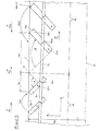
- FIG. 3 shows an illustration of the cutting movement of several knives of a cutting device.
- the elongated holes 17 n of the knives 9 n are also shown.
- the distances A n between the knives 9 n are significantly smaller than the cutting lengths S n of the respective knives 9 n .
- the dashed line 22 indicates the position of the cutting surface 9a n at the end of the cutting process of the knife 9 n .
- the bolts 21 n define the pivot points of the knives 9 n .
- Figure 4 outlines the cutting movement of a single knife 9 with the two cutting surfaces 9a and 9b again in more detail.
- the knife Before the cutting process begins, the knife is in the rest position R 1 . In this position the knife 9 is shown broken.
- the knife 9 has made a cut with the cutting length S in the material web 7.
- the knife remains in the second rest position R 2 .
- the knife 9 also has a second cutting surface 9b and can therefore also cut if the cutting process is carried out in the opposite direction.
- FIG. 5 outlines a cutting process in which a first group N of knives 9n, 9n-1 etc. performs a rotary movement with a negative direction of rotation while cutting, while a second group M of knives 9m, 9m + 1 etc. makes a rotational movement with a positive direction of rotation ,
- the knife 9n covers an angle - ⁇ .
- the different cutting direction of the two knife groups M and N is sketched again by the curved arrows 22 N and 22 M.
- the cutting lengths of the knives are matched to one another in such a way that a continuous cut takes place over the entire width of the material web 7.
- this description applies to knives 9 n and 9 m in FIG. 5 - a collision of the two knives must also be avoided.
- the knife 9m does not reach the overlap point O until the knife 9n has already completed the cutting process and is within its entire width within the radius of the film roll R F.
- Figure 5 also shows that it is possible using a single force here acts in the axial direction, the opposite rotational movements of the two knife groups N and M.
- the push-pull rod engages 23 for this purpose with the pin 16n below the pivot points of the blades 21 17 9 n, 9 n-1 n into the unillustrated slots of a group N.
- the pull and push rod 23 runs in this embodiment straight in the axial direction - that is, parallel to the main axis of symmetry 24 of the roller.
- the knives of groups N and M have different designs.
- the bolts 21n of group N are located above the push and pull rod 23, while the bolts 21m of the other group M are arranged below the rod 23.
- the knives of the two knife groups can also be less regular than in the example outlined. Among other things, an alternating Arrangement of knives from both groups N and M conceivable.
- Figure 6 shows another embodiment of the invention with a Circular cutting device, which is a disk-shaped, essentially round Knife 25 has, which cuts the film web 7, so that the left of the round knife 25 the severed film web 34 can be seen.
- a Circular cutting device which is a disk-shaped, essentially round Knife 25 has, which cuts the film web 7, so that the left of the round knife 25 the severed film web 34 can be seen.
- the round knife 25 rotates about the axis 26, which thus has an axis of rotation 36 defined, which is perpendicular to the plane defined by the axial (z) and Radial coordinates (r) is spanned in the reference system of the roller.
- the torque for the rotational movement is provided by the drive unit 28 provided and from the shaft 29 via the belt 27 to the axis 26 in Transfer pivot point 36 of the knife 25.
- FIG. 7 shows a sketch of several knives with exemplary shaped ones Cutting blades that further improve the cutting process.
- Knives are used for this purpose, in which special shapes of these knives have been made directly at the contact point P K , at which the knives 9 Z and 9 z + 3 come into contact with the material web 7 for the first time.
- the knife 9z has a semicircular recess 51 in the area of its cutting blade directly below the point P k .
- the presence of this semicircular recess 51 creates an angle ⁇ between the upper region of the cutting edge 50 of the knife 9 z and the edge 49, which is less than 90 °.
- a force component arises in the radial direction (r) during the cutting process of the knife 9 z before the knife reaches the apex of the cutting movement P s shown in FIG.
- the action of the knife on the web is advantageously changed by the measure shown.
- the knife 9 z + 3 consists of two parts 45 and 46.
- the part 45 is wedge-shaped and shaped so that an angle ⁇ is formed between the cutting edge 48 and the edge 47, which is also less than 90 °.
- Both the knife 9 z and the knife 9 z + 3 are merely exemplary designs of knives which have edges in the immediate vicinity of the point P k , which are at an angle of less than 90 ° and which are already in an early phase of the cutting process fold in the mentioned force effect. It is particularly advantageous to use knives of the type described on the edge of the material web 7 resting on the lateral surface 3. However, using knives of the type described for severing the material web 7 over its entire width can also be advantageous.
- Knives of the knife group M 9m, 9m + 1 ... angle - ⁇ angle + ⁇ Axial component of the force on the material web
- F n Axial component of the force on the material web
- F n resulting axial component of the force on the material web
- G linear force
- F L Radius of the film wrap
- N, M. O Knife axis of rotation
Landscapes
- Life Sciences & Earth Sciences (AREA)
- Forests & Forestry (AREA)
- Engineering & Computer Science (AREA)
- Mechanical Engineering (AREA)
- Perforating, Stamping-Out Or Severing By Means Other Than Cutting (AREA)
- Nonmetal Cutting Devices (AREA)
- Harvester Elements (AREA)
Abstract
Description
- Fig. 1:
- Einen Schnitt durch eine Schneid- und Transportwalze
- Fig. 2:
- Eine Skizze einer Schneidvorrichtung mit mehreren Messern. Die die Schneidvorrichtung enthaltende Walze ist nicht dargestellt.
- Fig. 3:
- Eine Darstellung der Schneidbewegung mehrerer Messer
- Fig. 4:
- Eine Darstellung verschiedener Phasen der Schneidbewegung eines Messers
- Fig. 5:
- Eine Skizze eines Schneidvorgangs bei dem zwei Messergruppen beim Schneiden Drehbewegungen mit entgegengesetztem Drehsinn ausführen.
- Fig. 6:
- Einen Schnitt durch eine Schneid- und Transportwalze, die eine Kreischneideinrichtung enthält.
- Fig. 7:
- Eine Skizze mehrerer Messer mit beispielhaft ausgeformten Schneidklingen, welche den Schneidvorgang weiter erleichtern.
| Bezugszeichenliste | |||
| Schneid- und Transportwalze | 1 | ||
| Kasten der Schneidvorrichtung | 2 | ||
| Mantelfläche | 3 | ||
| Schneidvorrichtung | 4 | ||
| Messer | 5 | ||
| Messerspalt | 6 | ||
| Materialbahn | 7 | ||
| Messerbalken | 8 | ||
| Messer | 9 | 9n | 9m |
| t-Profil | 10 | ||
| horizontale Auskragung des t-Profils | 11 | ||
| Sicherungsplatte | 12 | ||
| Schlitten der Zug-Schubstange | 13 | ||
| Zug-Schubstange | 14 | ||
| Bohrungen | 15 | ||
| Zapfen | 16 | 16n | 16m |
| Langlöcher | 17 | 17n | 17m |
| vertikale Auskragung des t-Profils | 18 | ||
| Führungsplatte | 19 | ||
| Führungswulste | 20 | ||
| Bolzen | 21 | ||
| gekrümmte Pfeile in Richtung des Drehsinns | 22n | 22m | |
| Zug- Schubstange | 23 | ||
| Hauptsymmetrieachse der Walze | 24 | ||
| rundes Messer | 25 | ||
| Achse des runden Messers | 26 | ||
| Band | 27 | ||
| Antriebseinheit | 28 | ||
| Welle | 29 | ||
| Schlitten der Kreisschneiseeinheit | 30 | ||
| Schiene | 31 | ||
| Origazylinder | 32 | ||
| Zapfen des Origazylinders | 33 | ||
| durchtrennte Folienbahn | 34 | ||
| Kreisschneideeinrichtung | 35 | ||
| Drehachse des runden Messers | 36 | ||
| gerader Pfeil | 37 | ||
| gekrümmter Pfeil | 38 | ||
| Origazylinder | |||
| vertikale Wand des Kastens der Schneideeinrichtung | 40a | 40b | |
| Zapfen des Origazylinders | 41 | ||
| Boden des Kastens der Schneideeinrichtung | 42 | ||
| Schlitz in der horizontalen Auskragung des t-Profils | 43 | ||
| gestrichelte Linie | 44 | ||
| Teil des Messers 9z+3 | 45 | ||
| Teil des Messers 9z+3 | 46 | ||
| Kante des Messers 9z+3 | 47 | ||
| Schneidkante des Messers 9z+3 | 48 | ||
| Kante des Messers 9z | 49 | ||
| Oberer Teil der Schneidante des Messers 9z | 50 | ||
| halkreisförmige Ausnehmung des Messers 9z | 51 | ||
| Radialkoordinaten | r | ||
| Axialkoordinaten | z | ||
| Winkelkoordinaten | ϕ | ||
| Abstände zwischen den Messern | An | ||
| Schnittlängen der jeweiligen Messer | Sn | Sm | |
| erste Ruheposition des Messers | R1 | ||
| zweite Ruheposition des Messers | R2 | ||
| Kraftwirkung auf die Folie | F1 | ||
| Kraftwirkung auf die Folie | F2 | ||
| Schneidfläche | 9a | ||
| Schneidfläche | 9b | ||
| Messergruppe | N | ||
| Messergruppe | M | ||
| Messer der Messergruppe N | 9n, 9n-1... | ||
| Messer der Messergruppe M | 9m, 9m+1... | ||
| Winkel | -α | ||
| Winkel | +β | ||
| Axialkomponente der Kraft auf die Materialbahn | Fn | ||
| Axialkomponente der Kraft auf die Materialbahn | Fn | ||
| resultierende Axialkomponente der Kraft auf die Materialbahn | FG | ||
| lineare Kraft | FL | ||
| Radius des Folienwickels | RF | ||
| Überlapppunkt von Schneidbewegungen von Messern, die unterschiedlichen Messergruppen N, M angehören | O | ||
| Drehachse der Messer | D | ||
| Scheitelpunkt des Messers | PS | ||
| Punkt der Kontaktaufnahme zwischen Messer und Materialbahn | Pk | ||
| Winkel | χ | ||
| Winkel | δ |
Claims (24)
wobei die Schneidvorrichtung zumindest ein von einem Messerhalter geführtes Messer enthält, das seinerseits zumindest eine Schneidfläche besitzt,
wobei das zumindest eine Messer schwenkbar an dem Messerhalter angelenkt ist und beim Schneiden der Materialbahn durch die Öffnung in der Mantelfläche ausgreift
dadurch gekennzeichnet, dass
die schwenkbare Anlenkung des zumindest einen Messers (9) für die zumindest eine Schneide (9a) des Messers eine Drehachse definiert, die entweder parallel oder in spitzem Winkel zu einem Lot auf der Ebene steht, welche von den Radial- (r) und Axial- (z) Koordinaten der Schneid-und Transportwalze (1) aufgespannt wird.
dadurch gekennzeichnet, dass
das zumindest eine Messer (9) an einem Messerbalken (8) angebracht ist, der eine Translationsbewegung in radialer und/oder axialer Richtung der Schneid- oder Transportwalze (1) ausführen kann.
gekennzeichnet durch
Saugvorrichtungen oder Vakuumkammern innerhalb der Mantelfläche der Schneid- und Transportwalze, welche Verbindungen mit Öffnungen in der Mantelfläche der Schneid- und Transportwalze besitzen.
gekennzeichnet durch
Vorrichtungen zum Öffnen und Schließen der Verbindungen zwischen den Saugvorrichtungen oder Vakuumkammern innerhalb der Mantelfläche und den Öffnungen in der Mantelfläche.
gekennzeichnet durch
eine Vorrichtung zur Bereitstellung einer Kraft, die innerhalb der Mantelfläche des Schneid- und Transportzylinders angebracht ist und die besagte Kraft auf eine Zug- Schubstange (14, 23) überträgt, die in der radialen Richtung der Schneid- und Transportwalze (1) versetzt zu dem Drehpunkt des zumindest einen Messers (9) an dieses Messer angelenkt ist.
dadurch gekennzeichnet, dass
an der Zug- Schubstange Zapfen (16) angebracht sind, die durch Langlöcher (17) in dem zumindest einen Messer (9) hindurchgreifen und die Messer antreiben.
dadurch gekennzeichnet, dass
die Zug- Schubstange (14) als Schlitten (13) ausgeprägt ist, der zwischen Führungselementen der Schneidvorrichtung läuft.
dadurch gekennzeichnet, dass
das zumindest eine Messer (9) aus einem flachen blechartigen Material besteht, wobei die Materialstärke klein gegen die Messerbreite ist.
dadurch gekennzeichnet, dass
die Schneidvorrichtung eine Mehrzahl von Messern (9n , 9n+1 ...) enthält, deren Schneidklingen (9a, 9b) in der jeweiligen Ruhestellung Abstände (Sn ) voneinander haben, die jeweils kleiner oder gleich der Länge des Schnitts sind, den das zugeordnete Messer (9n ) in die Materialbahnen einbringt.
dadurch gekennzeichnet, dass
die Schneidvorrichtung Messer (9) unterschiedlicher Länge oder Messer, die an Drehpunkten aufgehängt sind, die in der radialen Richtung der Walze versetzt zueinander positioniert sind, enthält.
dadurch gekennzeichnet dass
an dem Messerbalken eine Kreisschneideinrichtung, die ein scheibenförmiges, im wesentlichen rundes Messer vorzugsweise mit einem Elektromotor in eine Rotationsbewegung versetzt, angebracht ist.
dadurch gekennzeichnet, dass
die Schneidbewegung, welche bei dem Schneidvorgang von den Schneidflächen (9a, 9b) des mindestens einen Messers ausgeführt wird, rotatorische Komponenten aufweist,
wobei die Roatationsbewegungen des zumindest einen Messers jeweils um Achsen verlaufen, die entweder parallel oder in spitzem Winkel zu einem Lot auf der Ebene stehen, welche von den Radial- (r) und Axial-(z) Koordinaten der Schneid- und Transportwalze aufgespannt wird.
dadurch gekennzeichnet, dass
die Schneidbewegung, welche bei dem Schneidvorgang von den Schneidflächen (9a, 9b) des mindestens einen Messers ausgeführt wird, auch translatorische Komponenten enthält.
dadurch gekennzeichnet, dass
die Schneidflächen (9a, 9b) des mindestens einen Messers bei dem Schneidvorgang einen Winkel überstreichen, der kleiner als 360° ist.
gekennzeichnet durch die Abfolge folgender Verfahrensschritte:
eine innerhalb der Mantelfläche des Zylinders bereitgestellte Kraft zur Erzeugung der Schwenkbewegung des zumindest einen Messers mechanisch in Drehmoment umgesetzt wird.
dadurch gekennzeichnet, dass
unterschiedliche Messer einer Schneidvorrichtung zumindest teilweise zu unterschiedlichen Zeitpunkten in Kontakt mit der zu schneidenden Folienbahn gebracht werden.
dadurch gekennzeichnet, dass
die Schneidvorrichtung mehrere Messer enthält, von denen zumindest eines einer Messergruppe (N) und zumindest ein anderes einer Messergruppe (M) zugeordnet wird und
wobei das zumindest eine Messer (9n) der ersten Gruppe während eines Schneidvorgangs eine Schneidbewegung ausführt, deren rotatorische Komponenten einen Drehsinn besitzen, der dem Drehsinn der rotatorischen Komponenten der Schneidbewegung des zumindest einen Messers (9m) der zweiten Gruppe (M) entgegengerichtet ist.
dadurch gekennzeichnet, dass
die Drehbewegungen mit entgegengesetztem Drehsinn, welche die Messer der beiden Messergruppen (N, M) ausführen, durch die Umsetzung einer Kraft hervorgerufen werden, indem Komponenten der Kraft (FL) auf das zumindest eine Messer (9n) der ersten Gruppe (N) in radialer Richtung unterhalb der Drehachse der Messerbewegung (21n) übertragen werden, während Komponenten der Linearkraft auf das zumindest eine Messer (9m) der zweiten Gruppe (M) in radialer Richtung oberhalb der Drehachse der Messerbewegung (21m) einwirken.
dadurch gekennzeichnet, dass
die Drehbewegungen mit entgegengesetztem Drehsinn, welche die Messer der beiden Messergruppen (N, M) ausführen, durch Antriebseinrichtung zur Bereitstellung eines Drehmomentes hervorgerufen werden, wobei das Drehmoment für die zweite Messergruppe mit getrieblichen Mitteln umgerichtet und auf die Messer übertragen wird.
gekennzeichnet durch folgende Verfahrensschritte:
dadurch gekennzeichnet, dass
das rotierende scheibenförmige, im wesentlichen runde Messer (25) zwischen den Schneidvorgängen stillsteht.
dadurch gekennzeichnet, dass
das rotierende scheibenförmige, im wesentlichen runde Messer (25) nach dem Schneidvorgang aus der ersten in die zweite Ruhestellung zurückgefahren wird.
dadurch gekennzeichnet, dass
zumindest ein Messer verwendet wird, das in unmittelbarer Nähe des Punktes (Pk), an dem das zumindest eine Messer bei Beginn des Schneidvorgangs erstmals in Kontakt mit der Materialbahn kommt, eine obere Kannte (47, 49) besitzt, die zu der zumindest einen Schneidkante (48, 50) in einem Winkel (χ, δ) steht, der kleiner als 90° ist.
Applications Claiming Priority (2)
| Application Number | Priority Date | Filing Date | Title |
|---|---|---|---|
| DE10047545A DE10047545B4 (de) | 2000-09-22 | 2000-09-22 | Schneid- und Transportwalze mit integrierter Schneidvorrichtung mit schwenkbaren Schneidflächen und Verfahren zum Schneiden von Materialbahnen mithilfe einer solchen Walze |
| DE10047545 | 2000-09-22 |
Publications (3)
| Publication Number | Publication Date |
|---|---|
| EP1190821A2 true EP1190821A2 (de) | 2002-03-27 |
| EP1190821A3 EP1190821A3 (de) | 2004-11-03 |
| EP1190821B1 EP1190821B1 (de) | 2009-03-25 |
Family
ID=7657605
Family Applications (1)
| Application Number | Title | Priority Date | Filing Date |
|---|---|---|---|
| EP01119891A Expired - Lifetime EP1190821B1 (de) | 2000-09-22 | 2001-08-17 | Schwenkbare Einzelmesser sowie Verfahren zum Schneiden mit solchen Messern |
Country Status (7)
| Country | Link |
|---|---|
| US (1) | US6766722B2 (de) |
| EP (1) | EP1190821B1 (de) |
| JP (1) | JP2002187669A (de) |
| AT (1) | ATE426490T1 (de) |
| BR (1) | BR0104166A (de) |
| CA (1) | CA2357579A1 (de) |
| DE (2) | DE10047545B4 (de) |
Cited By (2)
| Publication number | Priority date | Publication date | Assignee | Title |
|---|---|---|---|---|
| WO2009106303A1 (de) * | 2008-02-26 | 2009-09-03 | Kuka Systems Gmbh | Bearbeitungseinrichtung und bearbeitungsverfahren zum trennen von randseitigen überständen |
| CN111169027A (zh) * | 2020-01-09 | 2020-05-19 | 苏州惠国塑料制品有限公司 | Pe膜高效吹塑生产线 |
Families Citing this family (13)
| Publication number | Priority date | Publication date | Assignee | Title |
|---|---|---|---|---|
| US7320269B2 (en) * | 2001-12-19 | 2008-01-22 | Windmoeller & Hoelscher Kg | Blade slit covering on a cutting and feed roller |
| DE10321778B4 (de) * | 2003-05-14 | 2006-03-30 | Windmöller & Hölscher Kg | Schneid- und Transportwalze in einer Wickelvorrichtung zum Aufwickeln von Materialbahnen |
| DE102004055734A1 (de) * | 2004-11-18 | 2006-06-01 | Kiefel Extrusion Gmbh | Verfahren und Vorrichtung zum rechts- und linksdrehenden Aufwickeln von Materialbahnen |
| US20080223975A1 (en) * | 2007-03-14 | 2008-09-18 | Miroslav Planeta | Reversible surface winder |
| KR100916076B1 (ko) * | 2007-12-10 | 2009-09-08 | 주식회사 포스코 | 절단장치 |
| CN203768712U (zh) * | 2013-11-08 | 2014-08-13 | 株式会社瑞光 | 织物切断装置 |
| US11434102B2 (en) * | 2019-09-03 | 2022-09-06 | Applied Motion Systems, Inc. | Core slabbing apparatus |
| CN111113523B (zh) * | 2020-01-10 | 2024-03-12 | 中国建筑第八工程局有限公司 | 一种锚杆防水卷材切割装置及方法 |
| CN112642969A (zh) * | 2020-12-30 | 2021-04-13 | 赣州市领沃电子科技有限公司 | 一种基于5g通讯技术的数据线定长切断装置 |
| CN112917986A (zh) * | 2021-01-20 | 2021-06-08 | 宜春惠众生物能源有限公司 | 一种机制炭生产用成型机 |
| CN113427559B (zh) * | 2021-07-02 | 2023-03-10 | 西安交通大学医学院第二附属医院 | 一种纳米胎球蛋白试纸监测糖尿病视网膜病变及制作工艺 |
| CN117283650B (zh) * | 2023-10-08 | 2025-07-25 | 洛阳信德科技有限公司 | 一种用于壳体内部喷涂层自动裁切工装的使用方法 |
| CN118992669B (zh) * | 2024-10-22 | 2025-02-07 | 安徽云中光电科技有限公司 | 一种绝缘胶带切段装置 |
Family Cites Families (13)
| Publication number | Priority date | Publication date | Assignee | Title |
|---|---|---|---|---|
| US1421969A (en) * | 1920-09-01 | 1922-07-04 | Loeb Rudolf | Means for cutting fabrics |
| US2916956A (en) * | 1956-06-14 | 1959-12-15 | Salomon Jacob | Pivotally mounted reciprocating cutter for a continuously moving suctionally held web |
| US3590695A (en) * | 1968-04-04 | 1971-07-06 | Jiffy Mfg Co | Sheet perforating and joining system |
| US3943686A (en) * | 1974-09-05 | 1976-03-16 | Fmc Corporation | Wrapping machine with severing blade in crimping head |
| CA1184112A (en) * | 1982-08-24 | 1985-03-19 | Oliver H. Vogt | Cutter for making arcuate cuts in travelling webs |
| CN1026567C (zh) * | 1990-05-01 | 1994-11-16 | 日本石油化学株式会社 | 在带状体上形成狭缝的方法及其装置 |
| ES2051250A6 (es) * | 1991-03-26 | 1994-06-01 | Rojas Manuel Jimenez | Mejoras en el objeto de la patente principal n{ 9100972 por:"dispositivo de sujecion de flejes en cilindros de perforacion y corte para maquinaria de artes graficas. |
| US5193425A (en) * | 1991-05-14 | 1993-03-16 | Nwf Industries | Chip impalement spears for rotary cutters |
| DE9413238U1 (de) * | 1994-08-17 | 1994-10-13 | Reinhold, Klaus, 49525 Lengerich | Vorrichtung zum Aufwickeln von Materialbahnen mit einer Schneid- und Transportwalze |
| DE19504162C2 (de) * | 1995-02-08 | 1997-02-20 | Windmoeller & Hoelscher | In ihrem Durchmesser veränderbare Messerwalze |
| US6026727A (en) * | 1996-03-07 | 2000-02-22 | Lawrence Paper Company | Rotary scoring apparatus having retractable scoring blade |
| GB2346108A (en) * | 1999-01-29 | 2000-08-02 | Molins Plc | A sealing and cutting device for a packaging machine |
| EP1031401B1 (de) * | 1999-02-25 | 2003-07-02 | FOSBER S.p.A. | Vorrichtung zum Querschneiden von bahnförmigen Materialien |
-
2000
- 2000-09-22 DE DE10047545A patent/DE10047545B4/de not_active Expired - Fee Related
-
2001
- 2001-08-17 EP EP01119891A patent/EP1190821B1/de not_active Expired - Lifetime
- 2001-08-17 DE DE50114783T patent/DE50114783D1/de not_active Expired - Lifetime
- 2001-08-17 AT AT01119891T patent/ATE426490T1/de active
- 2001-09-20 BR BR0104166-5A patent/BR0104166A/pt not_active Application Discontinuation
- 2001-09-20 CA CA002357579A patent/CA2357579A1/en not_active Abandoned
- 2001-09-24 US US09/960,729 patent/US6766722B2/en not_active Expired - Fee Related
- 2001-09-25 JP JP2001291948A patent/JP2002187669A/ja active Pending
Cited By (2)
| Publication number | Priority date | Publication date | Assignee | Title |
|---|---|---|---|---|
| WO2009106303A1 (de) * | 2008-02-26 | 2009-09-03 | Kuka Systems Gmbh | Bearbeitungseinrichtung und bearbeitungsverfahren zum trennen von randseitigen überständen |
| CN111169027A (zh) * | 2020-01-09 | 2020-05-19 | 苏州惠国塑料制品有限公司 | Pe膜高效吹塑生产线 |
Also Published As
| Publication number | Publication date |
|---|---|
| US20020066347A1 (en) | 2002-06-06 |
| CA2357579A1 (en) | 2002-03-22 |
| BR0104166A (pt) | 2002-05-28 |
| EP1190821B1 (de) | 2009-03-25 |
| US6766722B2 (en) | 2004-07-27 |
| ATE426490T1 (de) | 2009-04-15 |
| EP1190821A3 (de) | 2004-11-03 |
| JP2002187669A (ja) | 2002-07-02 |
| DE10047545B4 (de) | 2007-12-27 |
| DE10047545A1 (de) | 2002-05-02 |
| DE50114783D1 (de) | 2009-05-07 |
Similar Documents
| Publication | Publication Date | Title |
|---|---|---|
| DE2547337C3 (de) | Vorrichtung zum Schneiden und Rillen einer fortlaufenden Flachmaterialbahn | |
| DE10047545B4 (de) | Schneid- und Transportwalze mit integrierter Schneidvorrichtung mit schwenkbaren Schneidflächen und Verfahren zum Schneiden von Materialbahnen mithilfe einer solchen Walze | |
| DE2436717A1 (de) | Schlitz- und falzvorrichtung fuer durchlaufende materialbahnen | |
| DE2532250B2 (de) | Vorrichtung an einer Verpackungsmaschine zum Querschneiden von laufendem Bahnmaterial mit einem Sägezahnmesser | |
| DE2756884C2 (de) | Vorrichtung zum Herstellen von Signaturen | |
| DE19516953A1 (de) | Vorrichtung zum Seitenschneiden von Papier | |
| EP0219890B1 (de) | Verschiebe-Einrichtung | |
| DE3017872C2 (de) | Längsschneid-und Kerbvorrichtung | |
| DE19857507A1 (de) | Falzapparat für Rotationsdruckmaschinen | |
| DE19853415A1 (de) | Punkturloser Falzapparat für Rotationsdruckmaschinen | |
| EP2396227B1 (de) | Schneid- und spreizvorrichtung | |
| DE102008033775B4 (de) | Wellpappe-Anlage mit einer Schleusen-Einrichtung und Verfahren zum Ausschleusen von Stücken einer Wellpappe-Bahn | |
| DE102004020305A1 (de) | Falzapparat für Sammelbetrieb | |
| DE19927920A1 (de) | Schneideinrichtung im Falzapparat einer Rotationsdruckmaschine und Falzapparat mit einer solchen Schneideinrichtung | |
| EP0673729A1 (de) | Einrichtung zum Beschneiden von Druckprodukten | |
| DE10254332A1 (de) | Falzzylinder | |
| WO1992007693A1 (de) | Unterstützungseinrichtung | |
| EP1810799B1 (de) | Vorrichtungen zur Bearbeitung einer laufenden Materialbahn | |
| EP2061714B1 (de) | Falzapparat mit einem falzmesserzylinder und einem falzklappenzylinder | |
| CH340700A (de) | Verfahren zum Perforieren von Papier und Einrichtung zur Durchführung dieses Verfahrens | |
| EP1742865A2 (de) | Zylinder für die bearbeitung von flachmaterial und zylinder in einem falzapparat einer druckmaschine | |
| DE4407375A1 (de) | Falteinrichtung für Blattlagen | |
| DE69001061T2 (de) | Schervorrichtung mit rotierendem messer. | |
| DE102016002905A1 (de) | Verfahren und Vorrichtung zum Nuten von Pappenzuschnitten | |
| DE3143011A1 (de) | Steuerkurvenbetaetigte greifvorrichtung fuer bedruckte papierbahnen |
Legal Events
| Date | Code | Title | Description |
|---|---|---|---|
| PUAI | Public reference made under article 153(3) epc to a published international application that has entered the european phase |
Free format text: ORIGINAL CODE: 0009012 |
|
| AK | Designated contracting states |
Kind code of ref document: A2 Designated state(s): AT BE CH CY DE DK ES FI FR GB GR IE IT LI LU MC NL PT SE TR |
|
| AX | Request for extension of the european patent |
Free format text: AL;LT;LV;MK;RO;SI |
|
| PUAL | Search report despatched |
Free format text: ORIGINAL CODE: 0009013 |
|
| AK | Designated contracting states |
Kind code of ref document: A3 Designated state(s): AT BE CH CY DE DK ES FI FR GB GR IE IT LI LU MC NL PT SE TR |
|
| AX | Request for extension of the european patent |
Extension state: AL LT LV MK RO SI |
|
| 17P | Request for examination filed |
Effective date: 20050503 |
|
| AKX | Designation fees paid |
Designated state(s): AT BE CH CY DE DK ES FI FR GB GR IE IT LI LU MC NL PT SE TR |
|
| 17Q | First examination report despatched |
Effective date: 20051209 |
|
| GRAP | Despatch of communication of intention to grant a patent |
Free format text: ORIGINAL CODE: EPIDOSNIGR1 |
|
| GRAS | Grant fee paid |
Free format text: ORIGINAL CODE: EPIDOSNIGR3 |
|
| GRAA | (expected) grant |
Free format text: ORIGINAL CODE: 0009210 |
|
| AK | Designated contracting states |
Kind code of ref document: B1 Designated state(s): AT BE CH CY DE DK ES FI FR GB GR IE IT LI LU MC NL PT SE TR |
|
| REG | Reference to a national code |
Ref country code: GB Ref legal event code: FG4D Free format text: NOT ENGLISH |
|
| REG | Reference to a national code |
Ref country code: CH Ref legal event code: EP |
|
| REG | Reference to a national code |
Ref country code: IE Ref legal event code: FG4D Free format text: LANGUAGE OF EP DOCUMENT: GERMAN |
|
| REF | Corresponds to: |
Ref document number: 50114783 Country of ref document: DE Date of ref document: 20090507 Kind code of ref document: P |
|
| PG25 | Lapsed in a contracting state [announced via postgrant information from national office to epo] |
Ref country code: FI Free format text: LAPSE BECAUSE OF FAILURE TO SUBMIT A TRANSLATION OF THE DESCRIPTION OR TO PAY THE FEE WITHIN THE PRESCRIBED TIME-LIMIT Effective date: 20090325 |
|
| PG25 | Lapsed in a contracting state [announced via postgrant information from national office to epo] |
Ref country code: SE Free format text: LAPSE BECAUSE OF FAILURE TO SUBMIT A TRANSLATION OF THE DESCRIPTION OR TO PAY THE FEE WITHIN THE PRESCRIBED TIME-LIMIT Effective date: 20090625 |
|
| NLV1 | Nl: lapsed or annulled due to failure to fulfill the requirements of art. 29p and 29m of the patents act | ||
| REG | Reference to a national code |
Ref country code: IE Ref legal event code: FD4D |
|
| PG25 | Lapsed in a contracting state [announced via postgrant information from national office to epo] |
Ref country code: PT Free format text: LAPSE BECAUSE OF FAILURE TO SUBMIT A TRANSLATION OF THE DESCRIPTION OR TO PAY THE FEE WITHIN THE PRESCRIBED TIME-LIMIT Effective date: 20090831 Ref country code: ES Free format text: LAPSE BECAUSE OF FAILURE TO SUBMIT A TRANSLATION OF THE DESCRIPTION OR TO PAY THE FEE WITHIN THE PRESCRIBED TIME-LIMIT Effective date: 20090706 |
|
| PG25 | Lapsed in a contracting state [announced via postgrant information from national office to epo] |
Ref country code: NL Free format text: LAPSE BECAUSE OF FAILURE TO SUBMIT A TRANSLATION OF THE DESCRIPTION OR TO PAY THE FEE WITHIN THE PRESCRIBED TIME-LIMIT Effective date: 20090325 |
|
| PG25 | Lapsed in a contracting state [announced via postgrant information from national office to epo] |
Ref country code: DK Free format text: LAPSE BECAUSE OF FAILURE TO SUBMIT A TRANSLATION OF THE DESCRIPTION OR TO PAY THE FEE WITHIN THE PRESCRIBED TIME-LIMIT Effective date: 20090325 Ref country code: IE Free format text: LAPSE BECAUSE OF FAILURE TO SUBMIT A TRANSLATION OF THE DESCRIPTION OR TO PAY THE FEE WITHIN THE PRESCRIBED TIME-LIMIT Effective date: 20090325 |
|
| PLBE | No opposition filed within time limit |
Free format text: ORIGINAL CODE: 0009261 |
|
| STAA | Information on the status of an ep patent application or granted ep patent |
Free format text: STATUS: NO OPPOSITION FILED WITHIN TIME LIMIT |
|
| BERE | Be: lapsed |
Owner name: WINDMOLLER & HOLSCHER K.G. Effective date: 20090831 |
|
| 26N | No opposition filed |
Effective date: 20091229 |
|
| PG25 | Lapsed in a contracting state [announced via postgrant information from national office to epo] |
Ref country code: MC Free format text: LAPSE BECAUSE OF NON-PAYMENT OF DUE FEES Effective date: 20090831 |
|
| REG | Reference to a national code |
Ref country code: CH Ref legal event code: PL |
|
| GBPC | Gb: european patent ceased through non-payment of renewal fee |
Effective date: 20090817 |
|
| PG25 | Lapsed in a contracting state [announced via postgrant information from national office to epo] |
Ref country code: CH Free format text: LAPSE BECAUSE OF NON-PAYMENT OF DUE FEES Effective date: 20090831 Ref country code: LI Free format text: LAPSE BECAUSE OF NON-PAYMENT OF DUE FEES Effective date: 20090831 |
|
| REG | Reference to a national code |
Ref country code: FR Ref legal event code: ST Effective date: 20100430 |
|
| PG25 | Lapsed in a contracting state [announced via postgrant information from national office to epo] |
Ref country code: BE Free format text: LAPSE BECAUSE OF NON-PAYMENT OF DUE FEES Effective date: 20090831 |
|
| PG25 | Lapsed in a contracting state [announced via postgrant information from national office to epo] |
Ref country code: FR Free format text: LAPSE BECAUSE OF NON-PAYMENT OF DUE FEES Effective date: 20090831 |
|
| PG25 | Lapsed in a contracting state [announced via postgrant information from national office to epo] |
Ref country code: GR Free format text: LAPSE BECAUSE OF FAILURE TO SUBMIT A TRANSLATION OF THE DESCRIPTION OR TO PAY THE FEE WITHIN THE PRESCRIBED TIME-LIMIT Effective date: 20090626 |
|
| PG25 | Lapsed in a contracting state [announced via postgrant information from national office to epo] |
Ref country code: GB Free format text: LAPSE BECAUSE OF NON-PAYMENT OF DUE FEES Effective date: 20090817 |
|
| PGFP | Annual fee paid to national office [announced via postgrant information from national office to epo] |
Ref country code: DE Payment date: 20100831 Year of fee payment: 10 |
|
| PG25 | Lapsed in a contracting state [announced via postgrant information from national office to epo] |
Ref country code: LU Free format text: LAPSE BECAUSE OF NON-PAYMENT OF DUE FEES Effective date: 20090817 |
|
| PG25 | Lapsed in a contracting state [announced via postgrant information from national office to epo] |
Ref country code: TR Free format text: LAPSE BECAUSE OF FAILURE TO SUBMIT A TRANSLATION OF THE DESCRIPTION OR TO PAY THE FEE WITHIN THE PRESCRIBED TIME-LIMIT Effective date: 20090325 |
|
| PG25 | Lapsed in a contracting state [announced via postgrant information from national office to epo] |
Ref country code: CY Free format text: LAPSE BECAUSE OF FAILURE TO SUBMIT A TRANSLATION OF THE DESCRIPTION OR TO PAY THE FEE WITHIN THE PRESCRIBED TIME-LIMIT Effective date: 20090325 |
|
| PGFP | Annual fee paid to national office [announced via postgrant information from national office to epo] |
Ref country code: AT Payment date: 20110726 Year of fee payment: 11 |
|
| PGFP | Annual fee paid to national office [announced via postgrant information from national office to epo] |
Ref country code: IT Payment date: 20110812 Year of fee payment: 11 |
|
| REG | Reference to a national code |
Ref country code: DE Ref legal event code: R119 Ref document number: 50114783 Country of ref document: DE Effective date: 20120301 |
|
| REG | Reference to a national code |
Ref country code: AT Ref legal event code: MM01 Ref document number: 426490 Country of ref document: AT Kind code of ref document: T Effective date: 20120817 |
|
| PG25 | Lapsed in a contracting state [announced via postgrant information from national office to epo] |
Ref country code: IT Free format text: LAPSE BECAUSE OF NON-PAYMENT OF DUE FEES Effective date: 20120817 |
|
| PG25 | Lapsed in a contracting state [announced via postgrant information from national office to epo] |
Ref country code: DE Free format text: LAPSE BECAUSE OF NON-PAYMENT OF DUE FEES Effective date: 20120301 Ref country code: AT Free format text: LAPSE BECAUSE OF NON-PAYMENT OF DUE FEES Effective date: 20120817 |