EP1189764B1 - Ringordnermechanik - Google Patents
Ringordnermechanik Download PDFInfo
- Publication number
- EP1189764B1 EP1189764B1 EP01929539A EP01929539A EP1189764B1 EP 1189764 B1 EP1189764 B1 EP 1189764B1 EP 01929539 A EP01929539 A EP 01929539A EP 01929539 A EP01929539 A EP 01929539A EP 1189764 B1 EP1189764 B1 EP 1189764B1
- Authority
- EP
- European Patent Office
- Prior art keywords
- ring binder
- binder mechanism
- mechanism according
- housing
- closing
- Prior art date
- Legal status (The legal status is an assumption and is not a legal conclusion. Google has not performed a legal analysis and makes no representation as to the accuracy of the status listed.)
- Expired - Lifetime
Links
- 230000007246 mechanism Effects 0.000 title claims abstract description 78
- 239000011230 binding agent Substances 0.000 title claims abstract description 76
- 230000000903 blocking effect Effects 0.000 claims abstract description 33
- 238000005452 bending Methods 0.000 claims description 2
- 238000000926 separation method Methods 0.000 claims 1
- 239000000463 material Substances 0.000 abstract description 2
- 230000000694 effects Effects 0.000 abstract 1
- 210000000629 knee joint Anatomy 0.000 abstract 1
- 230000000295 complement effect Effects 0.000 description 5
- 238000000034 method Methods 0.000 description 4
- 241001295925 Gegenes Species 0.000 description 3
- 230000000881 depressing effect Effects 0.000 description 3
- 239000002655 kraft paper Substances 0.000 description 3
- 238000003825 pressing Methods 0.000 description 3
- 230000006835 compression Effects 0.000 description 2
- 238000007906 compression Methods 0.000 description 2
- 230000036316 preload Effects 0.000 description 2
- 208000027418 Wounds and injury Diseases 0.000 description 1
- 230000015572 biosynthetic process Effects 0.000 description 1
- 238000010276 construction Methods 0.000 description 1
- 230000006378 damage Effects 0.000 description 1
- 230000001419 dependent effect Effects 0.000 description 1
- 230000000994 depressogenic effect Effects 0.000 description 1
- 238000011161 development Methods 0.000 description 1
- 230000018109 developmental process Effects 0.000 description 1
- 238000006073 displacement reaction Methods 0.000 description 1
- 208000014674 injury Diseases 0.000 description 1
- 238000004519 manufacturing process Methods 0.000 description 1
- 230000000149 penetrating effect Effects 0.000 description 1
- 239000012858 resilient material Substances 0.000 description 1
- 238000003860 storage Methods 0.000 description 1
Images






Classifications
-
- B—PERFORMING OPERATIONS; TRANSPORTING
- B42—BOOKBINDING; ALBUMS; FILES; SPECIAL PRINTED MATTER
- B42F—SHEETS TEMPORARILY ATTACHED TOGETHER; FILING APPLIANCES; FILE CARDS; INDEXING
- B42F13/00—Filing appliances with means for engaging perforations or slots
- B42F13/16—Filing appliances with means for engaging perforations or slots with claws or rings
- B42F13/20—Filing appliances with means for engaging perforations or slots with claws or rings pivotable about an axis or axes parallel to binding edges
- B42F13/22—Filing appliances with means for engaging perforations or slots with claws or rings pivotable about an axis or axes parallel to binding edges in two sections engaging each other when closed
- B42F13/26—Filing appliances with means for engaging perforations or slots with claws or rings pivotable about an axis or axes parallel to binding edges in two sections engaging each other when closed and locked when so engaged, e.g. snap-action
Definitions
- the invention relates to a ring binder mechanism with a cross section C or U-shaped housing with elastically bendable bearing legs for two mounting rails, which are on their mutually facing longitudinal edges Forming a hinge axis against each other and with their each other engage opposite longitudinal edges in the troughs of the bearing legs, and rigid with at least two at a defined longitudinal distance from each other connected to the mounting rails, through openings in a housing wall half rings reaching through and complementing each other in pairs to form a ring, the mounting rails around the hinge axis, taking the Half rings between an open position and a closed position below
- Overcoming a spring force generated by bending the bearing legs are limited pivotable against each other, and at least one via an actuator essentially parallel to the hinge axis relative slidable locking element is provided to the housing and to the mounting rails is in the closed position in a between the mounting rail and a housing wall formed free space blocking the pivoting movement engages and in the open position the swivel path around the hinge axis releases.
- ring binder mechanisms In ring binder mechanisms, it is known per se to attach the half-rings Mounting rails to be fastened by a housing made of resilient Material is encompassed.
- the mounting rails are inserted into the housing that they can take two rest positions, one open and one closed.
- the housing acts as a spring element, which the half rings in fixed in their open position and in their closed position.
- drivers or locking means In the area of the inner Longitudinal edges of the mounting rails are drivers or locking means, which ensure that the two mounting rails on these Long edges always lie flush against each other.
- the mounting rails have the function of a spring-loaded on the outer edges Toggle.
- the object of the invention is a ring binder mechanism to develop the automatically against the closing process unintentional opening is locked and yet simple and with little Force can also be used with one hand.
- the solution according to the invention is based on the idea that the locking element automatically in its closed position during the closing process arrives.
- the invention proposes that the at least one locking element under the action of a Closing spring is biased towards the closed position.
- a first embodiment of the invention which is mainly for Folder mechanics with two rings is suitable, it is proposed that the locking element on a rigidly connected to the operating lever Lever arm is arranged and that the actuating lever relative to the housing and limited to the mounting rails in the direction of displacement of the locking element is movable.
- the closing spring is useful between one fixed to the housing and an actuating lever fixed abutment and preferably designed as a leg spring.
- the actuating lever is on a control edge of the housing has guided control curve over which the actuating lever with its locking element when pivoting against the force of the closing spring is movable from a closed position towards the open position.
- the opening process of the rings is facilitated when the operating lever with an opening arm acting in the opening direction against the mounting rails is rigidly connected.
- the opening arm is useful arranged at such a distance from the locking element that the locking element in the closed position of the operating lever and Support rails under the action of the closing spring in the free space between Carrier rails and housing wall can be inserted and in the open position the action of the closing spring strikes against a housing-fixed catch.
- the locking element can also be used in the closing direction against the Carrier rails acting on the closing arm.
- the actuating lever has at least one axle element has that in the open position of the operating lever under the Action of the closing spring against a bearing surface fixed to the housing and an axis of rotation for the locking element when it is disengaged and Closing movement forms. Is in the closed position of the operating lever the axle element is lifted off the bearing surface fixed to the housing.
- the control curve can be through a wall opening of the housing and reaching through a passage opening in the joint area between the mounting rails Tax boom can be arranged while the control edge by a preferably bent boundary edge of the wall opening can be formed.
- the locking element on one by Lever opening is arranged in the housing, while the housing-fixed rest by a preferably bent Boundary edge of the wall opening is formed.
- an end stop fixed to the housing which is wedge-shaped in the closing direction can run and by a bulge engaging in the free space in a housing wall can be formed.
- the actuating lever in the intermediate area is stored and guided between two rings on the housing and one through the opening of one of the rings engaging arm. If the operating arm is on the opposite side of the Has locking element carrying lever arm, the mechanics by depressing of the operating arm is opened and by lifting the operating arm closed. On the other hand, if the operating arm after the same Side as the lever arm bearing the locking element, the Mechanics closed by pressing the actuating arm and by Lift open. On the closing path of the actuating arm in the last phase, the locking element automatically under the action of the closing spring moved to its closed position. The locking element ensures this that the rings are not opened by pulling the half rings apart can be. This gets on the opening path of the actuating arm Locking element in the last phase under the action of the closing spring a rest.
- the latching connection is designed so that it is actuated the actuating arm or the half rings in the closing direction can.
- the Closing spring is expediently designed as a compression spring. Accordingly the operating lever rests on one end of the push rod while the closing spring between the other end of the push rod and a housing-fixed abutment is clamped so that the operating lever pulling in the opening direction against the force of the closing spring the push rod attacks.
- each locking element via a tension member and an integrated in the tension member Closing spring is connected to the operating lever. It is advantageous each locking element has its own, preferably a piece of wire, Associated tension member, at least two of the tension members by a connecting bridge can preferably be connected in one piece. This makes it possible for each locking element to have its own closing spring assigned.
- the closing spring is advantageously a leg spring integrated in the tension member formed, one leg of the tension member with the actuating lever is connected and the other leg on a housing-fixed or support rail-fixed bearing and at a distance from the Support point is fixed to the associated locking element.
- the at least one locking element than in a guide opening Slider guided between the two mounting rails is formed, the one pointing in the closing direction, in the closed position has wedge-shaped closing surface engaging in the free space.
- the wedge surface primarily serves to compensate for tolerances.
- the wedge angle is chosen so that self-locking occurs in the closed position.
- the slide has an arrow-shaped end edge in the closing direction, while the guide opening on its boundary edge facing the front edge has an arrow shape complementary to this.
- the ring binder mechanisms shown in the drawing are mainly for Intake of loose perforated sheets determined, for example by Documents or printed matter.
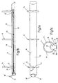
- the ring binder mechanisms exist essentially of a housing 10, at least two in a defined Longitudinally spaced from each other through openings 12 in a housing wall 13 reaching through and in pairs to one Ring 14 complementary half rings 16 and an operating lever 18 for Opening and closing the rings.
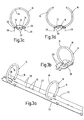
- the pair complementary to the ring 14 Half rings 16 are rigidly attached to two mounting rails 20 which their mutually facing longitudinal edges to form a hinge axis 22 abut each other and with their longitudinal edges facing away from each other 24 engage in mutually facing bearing grooves 26, which in the housing flanks 28 are stamped.
- the mounting rails 20 are so in the housing 10 inserted that they can take two rest positions, one open and a closed (Fig. 3c and d).
- the housing acts as a spring element, that the half rings 16 in their open position and in their closed position fixed.
- drivers 30 In the area of the inner longitudinal edges 22 of the mounting rails 20 there are drivers 30, which ensure that the two mounting rails 20 always lie flush against each other at their longitudinal edges.
- the mounting rails 20 have the function of a spring on the outer edges 24 held toggle. So that the mounting rails 20 to their Joint axis 22 with the half rings 16 being carried between the open position and the closed position overcoming one by the bend of the housing flanks 28 generated spring force pivoted against each other to a limited extent become.
- At least one is essentially via the actuating lever 18 parallel to the hinge axis 22 relative to the housing 10 and to the mounting rails 20 slidable locking element 32, 32 'provided in the Closed position in a between the mounting rails 20 and the housing wall 13 formed free space 34 blocking the swivel path of the Carrier rails engages and in the open position the swivel path around Joint axis 22 releases.
- a specialty of the constructions shown is that the at least one locking element 32 under the action at least one closing spring 36, 36 'biased towards the closed position is (Fig. 6a to c and Fig. 14a and e).
- the at least one locking element 32, 32 ' is opposite in the opening direction via the operating lever 18 the force of the closing spring 36, 36 'displaceable and unlockable (Figs. 8b and c; Figs. 14b and c).
- the open position there is at least one Locking element 32, 32 'against the action of the closing spring 36, 36' an opening catch (Fig. 8d; Fig. 14d).
- From the open position can the at least one locking element 32, 32 'either in the closing direction the operating lever 18 or by compressing the half rings 16 be released from the opening catch 38 against the force of the closing spring (Fig. 8e, Fig.
- the actuating lever 18 also has one against the mounting rails 20 striking in the opening direction and this from the closed to the open position overcoming those generated by the housing flanks 28 Spring force swinging through opening boom 40. Is further the operating lever 18 with one against the mounting rails 20 in the closing direction striking and this from the open to the closed position while overcoming the spring force applied by the housing flanks 28 pivoting closing arm 42 provided.
- the at least one locking element 32, 32 'in the closing direction also by actuating the half rings 16 directly or indirectly via the Support rails 20 can be displaced against the force of the closing spring 36, 36 ' and can be disengaged from the opening catch 38.
- the operating lever 18 points in the opening and closing directions two operating positions effective in different angular positions for a subsequent actuation of the mounting rails 20 and the at least a locking element 32, 32 '.
- FIGS. 1 to 9 are three equally spaced rings 14 as well as two locking elements 32, 32 'are provided, which are connected to one on one arranged front end of the housing 10 outside the annular spaces Actuating lever 18 can be actuated.
- Each locking element 32, 32 ' is its own Tension member 44, 44 'and its own closing spring 36, 36' assigned.
- the Tension members 44, 44 'are designed as pieces of wire which are connected by a connecting bridge 46 are integrally connected.
- the in the tension members 44, 44 'integrated closing springs 36, 36' are designed as leg springs, whose one leg 48 with the respective tension member 44, 44 ' the operating lever 18 is connected and the other leg 50 on supported on a mounting rail-fixed bearing 52 and at a distance from the support point is articulated on the associated locking element 32, 32 '.
- the locking elements 32, 32 ' are as in a guide opening 54 between the two mounting rails 20 guided slide formed, one in the closing direction pointing, engaging in the closed position in the free space 34 has wedge-shaped closing surface 56.
- the locking elements also point an arrow-shaped end edge 58 in the closing direction during the guide opening at its boundary edge facing the front edge 58 38 has an arrow shape complementary thereto.
- the operating lever 18 has two pairs from the side to the outside protruding bearing pins 70, 72, each against a housing-fixed Bearing and guide surface 74, 76 abut.
- the two storage and management areas 74, 76 form sections in the areas 74 ', 76' Rest 74 ', 76' for the relevant journal 70, 72.
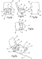
- the actuating lever further contains a hook element 78 into which the Tension members 44, 44 'are hooked in over the connecting bridge 46 (see FIG. 5a and 8a to e).
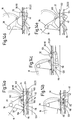
- Fig. 8a the closed position of the ring binder mechanism is shown, in which the Actuating lever 18 with its lever arm 18 'points obliquely upwards its journal 70, 72 against the associated bearing and guide surfaces 74, 76 abuts and with its closing arm 42 against the mounting rails 20 is present.
- the mounting rails are with their hinge axis 22 within of the housing 10 pressed down so that the half rings 16 under Formation of a closed ring 14 at the joint 80 against each other apply (Fig. 9a).
- the locking elements 32, 32 ' also engage with their end faces into the free space 34 and lie with their wedge-shaped closing surface 56 against the free-side inner surface of the mounting rails 20.
- FIG. 8b and c show the opening phase in which the operating lever 18 is depressed in the direction of the opening arrow 82.
- the opening arm 40 is pushed down against the mounting rails from below 20 and presses it by overcoming the flanks of the housing 28 generated spring force upwards until the mounting rails 20 against strike the housing wall 13 (Fig. 8c).
- the half rings 16 pivoted into its open position (Fig. 9b).
- the ring binder mechanism has two spaced-apart, passing through openings 12 in the housing wall 13 Half-ring pairs 16, which are not mirror-symmetrical and are out of round Complement rings 14.
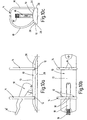
- This ring binder mechanism replaces the usual one Lever mechanism of a letter folder. Accordingly, it opens and closing the rings 14 in the intermediate area between the two Rings used actuating lever whose actuating arm 18 ' reaches through the opening of one of the rings 14.
- a peculiarity of this Embodiment is that the locking element 32 on one Lever arm 100 rigidly connected to the operating lever 18 is and that the operating lever 18 relative to the housing 10 and to the Support rails 20 can be moved together with the locking element 32 to a limited extent is.
- the lever arm 100 of the locking element extends through a wall opening 116 in the housing, while the housing-fixed latch 110 through a preferably bent boundary edge of the wall opening is formed is.
- the leg spring in the embodiment shown trained closing spring 36 is with one leg 48 on a lever-fixed Abutment 102 and with its other leg 50 on a housing-fixed Abutment 104 clamped.
- the operating lever has one control cam 108 guided on a control edge 106 of the housing 10, via which the actuating lever 18 and its locking element 32 when pivoting against the force of the closing spring 36 from a closed position is displaceable in the direction of the open position (cf. FIGS. 14 a and b).
- the control curve 108 is on a through a wall opening 116 of the housing 10 and a passage opening 118 in the joint area between the mounting rails 20 penetrating control boom 120 arranged while the control edge 106 by a preferably bent boundary edge of the Wall opening 116 is formed.
- the actuating lever is also in this case 18 with one acting in the opening direction against the mounting rails Opening boom 40 rigidly connected in this case by two pegs projecting on opposite sides is formed.
- the Opening bracket 40 is at such a distance from the locking element 32 arranged that the locking element in the closed position of the operating lever 18 and the mounting rails 20 under the action of the closing spring 36 in the free space 34 between the mounting rails 20 and the housing wall 13 is insertable and in the open position under the action of the closing spring 36 strikes against a housing-fixed latch 110.
- the locking element 32 or its lever arm 100 is in this case at the same time as in the closing direction against the support rails 20 acting closing arm 42 is formed.
- the locking element 32 In the closed position, the locking element 32 is against a housing-fixed End stop 122, which runs in a wedge shape in the closing direction and through a bulge engaging in the free space 34 in the housing wall 13 is formed.
- the actuating lever has two, designed as bearing journals on opposite sides projecting axle elements 112, which in the Open position of the actuating lever 32 under the action of the closing spring 36 bear against a bearing surface 114 fixed to the housing and an axis of rotation for the locking element 32 during its disengaging and closing movement forms and that in the closed position of the operating lever 32 from the housing Bearing surface 114 is lifted.
- the operating arm 18 'of the operating lever 18 according to the opposite side of the lever arm carrying the locking element 32 100.
- the mechanics by depressing the actuating arm 18 'opened and closed by lifting the actuating arm.
- the mechanism is closed by depressing the actuating arm and opened by lifting.
- the locking element 32 engages in the free space 34 between the mounting rails 20 and the housing wall 13.
- the Axle element 112 is raised from the bearing surface 114 and the actuating lever 18 strikes with the lever arm 100 in the region of the locking element 32 against the end stop 122, the actuating arm 18 ' through the opening of a pair of half rings 16 pointing obliquely upwards reaches through (Fig. 13a, 14a).
- the mechanics are opened in two phases: First, when pressing down of the lever arm 18 'in the direction of arrow 82 of the actuating lever 18 via the control cam 108 supported on the control edge 106 moved against the force of the closing spring 36 that the locking element 32 out of the free space 34 (Fig. 13b, 14b).
- pressing further down the lever arm 100 is formed by the control edge 106 Swivel axis pivoted upwards.
- the opening arm strikes 40 from below against the mounting rails 20 and takes them overcoming the spring force generated by the housing flanks 28 under simultaneous opening of the half rings 16 upwards (Fig. 13c and 14c).
- the lever 18 is now released, the locking element 32 moves with it frontal recess 124 under the action of the closing spring 36 to the housing-fixed latch 110.
- the lever arm 18 ' is up pivoted until the axillary element 112 abuts against the bearing surface 114 (Fig. 14d). In this position, the operating lever 18 takes its stable open position.
- the lever arm 18 is initially in the direction the arrow 84 pulled up. In doing so, he gets around by the axle element 112 defined axis by disengaging the locking element 32 from the housing-fixed rest 110 pivoted. At the same time, the mounting rails 20 over the closing arm 42 while overcoming the flanks of the housing 28 generated spring forces while closing the half rings 16 after pushed through below. The free space 34 is free, so that the locking element 32 can penetrate into it under the action of the closing spring 36 (FIG. 13e, 14e). At the same time, the actuating lever returns to its in Fig. 13a, 14a shown closed position.
- Fig. 13f is indicated in which position the operating lever 18 in the Assembly can be used in the housing 10.
- the invention relates to a ring binder mechanism for holding punched documents.
- the Ring binder mechanism has a housing 10 with resiliently bendable Housing flanks 28 on.
- Two support rails 20 are arranged in the housing, those in the manner of a toggle lever facing each other Longitudinal edges under the spring action of the housing flanks 28 against each other are pivotable.
- With the mounting rails 20 are at least two in defined longitudinal distance from each other, in pairs to one Ring 14 additional half rings 16 rigidly connected.
- Locking element 32 is provided which in the closed position in a between the mounting rails 20 and a housing wall 13 formed space 34 engages blocking the pivoting movement of the mounting rails 20 and in the open position releases the pivot path about the hinge axis 22.
- the at least one locking element 32 under the action of a closing spring 36 in the direction of the closed position is biased.
Landscapes
- Sheet Holders (AREA)
- Accommodation For Nursing Or Treatment Tables (AREA)
- Saccharide Compounds (AREA)
- Medicines Containing Material From Animals Or Micro-Organisms (AREA)
Description
- in Öffnungsrichtung über das Betätigungsorgan entgegen der Kraft der Schließfeder verschiebbar und dabei entriegelbar ist,
- in der Offenstellung unter der Einwirkung der Schließfeder gegen eine Öffnungsrast anliegt,
- in Schließrichtung über das Betätigungsorgan entgegen der Kraft der Schließfeder aus der Öffnungsrast lösbar ist,
- in Schließrichtung unter der Einwirkung der vorgespannten Schließfeder selbsttätig verriegelbar ist,
- in Schließrichtung durch Betätigen der Halbringe unmittelbar oder mittelbar über die Tragschienen entgegen der Kraft der Schließfeder verschiebbar und dabei aus der Öffnungsrast ausrastbar ist.
- als gegenüber dem Gehäuse verschwenkbarer Betätigungshebel ausgebildet ist,
- einen gegen die Tragschienen in Öffnungsrichtung anschlagenden und diese von der Schließ- in die Öffnungsstellung unter Überwindung der durch die Lagerschenkel erzeugten Federkraft durchschwenkenden Öffnungsausleger aufweist,
- einen gegen die Tragschienen in Schließrichtung anschlagenden und diese von der Öffnungs- in die Schließstellung unter Überwindung der durch die Lagerschenkel aufgebrachten Federkraft schwenkenden Schließausleger aufweist,
- in Öffnungs- und/oder Schließrichtung mindestens zwei in verschiedenen Winkelstellungen wirksame Betätigungspositionen für eine Folgebetätigung der Tragschienen und des mindestens einen Riegelelements aufweist.
- Fig. 1a bis c
- eine Draufsicht, einen Längsschnitt und eine Stirnseitenansicht einer Ringordnermechanik mit drei Ringen in geschlossenem Zustand;
- Fig. 2a bis c
- eine Untenansicht, eine Seitenansicht und eine Draufsicht der mit Tragschienen verbundenen Ringe der Ringordnermechanik nach Fig. 1 a bis c;
- Fig. 2d und e
- zwei vergrößerte Ausschnitte der Fig. 2a;
- Fig. 3a und b
- zwei verschiedene Ausschnitte aus der Tragschienen-Ringanordnung nach Fig. 2a bis c in schaubildlicher Darstellung;
- Fig. 3c und d
- je eine Stirnseitenansicht der Tragschienen-Ringanordnung in Schließstellung und in Offenstellung;
- Fig. 4a
- eine schaubildliche Darstellung des federelastischen Gehäuses der Ringordnermechanik nach Fig. 1a bis c;
- Fig. 4b
- eine ausschnittsweise Untenansicht des Gehäuses in schaubildlicher Darstellung;
- Fig. 4c und d
- eine Draufsicht und eine Stirnseitenansicht des Gehäuses;
- Fig. 4e
- einen Längsschnitt durch das federelastische Gehäuse in vergrößerter unterbrochener Darstellung;
- Fig. 5a
- eine schaubildliche Darstellung des Betätigungshebels der Ringordnermechanik nach Fig. 1a bis c;
- Fig. 5b bis e
- verschiedene Ansichten des Betätigungshebels nach Fig. 5a;
- Fig. 6a
- eine schaubildliche Darstellung des Zugglieds für die Riegelelemente der Ringordnermechanik nach Fig. 1a bis c;
- Fig. 6b
- eine Draufsicht des Zugglieds in unterbrochener, vergrößerter Darstellung;
- Fig. 6c
- eine Draufsicht auf das Zugglied mit integrierter Feder nach Fig. 6a in Offenstellung und in Schließstellung zur Veranschaulichung des Federwegs;
- Fig. 7a
- eine schaubildliche Darstellung der Riegelelemente;
- Fig. 7b bis e
- verschiedene Seitenansichten eines Riegelelements nach Fig. 7a;
- Fig. 8a bis e
- einen Schnitt durch die Ringordnermechanik in Schließstellung, in einer ersten und einer zweiten Öffnungsphase, in Offenstellung und in einer Schließphase;
- Fig. 9a und b
- einen Querschnitt durch die Ringordnermechanik in Schließstellung und in Offenstellung;
- Fig. 10a bis c
- eine Seitenansicht, eine Draufsicht und eine Stirnseitenansicht einer hebelbetätigten Ringordnermechanik mit zwei Ringen;
- Fig. 11a bis d
- die Ringe mit Tragschienen der Ringordnermechanik nach Fig. 10a bis c in schaubildlicher Darstellung, in einer Stirnseitenansicht, einer Seitenansicht und einer Draufsicht;
- Fig. 12a bis c
- den Betätigungshebel der Ringordnermechanik nach Fig. 10a bis c in schaubildlicher Darstellung, einer Seitenansicht und in Draufsicht;
- Fig. 13a bis e
- eine teilweise geschnittene Seitenansicht der Ringordnermechanik nach Fig. 10a bis c in verschiedenen Betätigungspositionen;
- Fig. 13f
- eine Darstellung entsprechend Fig. 13a bis e mit Betätigungshebel in Montagestellung;
- Fig. 14a bis e
- vergrößerte Ausschnitte aus den Fig. 13a bis e.
Claims (45)
- Ringordnermechanik mit einem im Querschnitt C- oder U-förmigen Gehäuse (10) mit federelastisch aufbiegbaren Flanken (28) für zwei Tragschienen (20), die an ihren einander zugewandten Längskanten unter Bildung einer Gelenkachse (22) gegeneinander anliegen und mit ihren einander abgewandten Längskanten (24) in Lagerrinnen (26) der Gehäuseflanken (28) eingreifen, und mit mindestens zwei in einem definierten Längsabstand voneinander starr mit den Tragschienen (20) verbundenen, durch Öffnungen (12) in einer Gehäusewand (13) hindurchgreifenden und sich paarweise zu einem Ring (14) ergänzenden Halbringen (16), wobei die Tragschienen (20) um die Gelenkachse (22) unter Mitnahme der Halbringe (16) zwischen einer Offenstellung und einer Schließstellung unter Überwindung einer durch Aufbiegen der Gehäuseflanken (28) erzeugten Federkraft begrenzt gegeneinander verschwenkbar sind, und wobei mindestens ein über ein Betätigungsorgan (18) im wesentlichen parallel zur Gelenkachse (22) relativ zum Gehäuse (10) und zu den Tragschienen (20) verschiebbares Riegelelement (32, 32') vorgesehen ist, das in der Schließstellung in einen zwischen den Tragschienen (20) und einer Gehäusewand (13) gebildeten Freiraum (34) unter Sperrung der Schwenkbewegung der Tragschienen (20) eingreift und in der Offenstellung den Schwenkweg der Tragschienen (20) um die Gelenkachse (22) freigibt, dadurch gekennzeichnet, daß das mindestens eine Riegelelement (32, 32') unter der Einwirkung einer Schließfeder (36, 36') in Richtung Schließstellung vorgespannt ist.
- Ringordnermechanik nach Anspruch 1, dadurch gekennzeichnet, daß das Betätigungsorgan (18) als gegenüber dem Gehäuse (10) verschwenkbarer Betätigungshebel ausgebildet ist.
- Ringordnermechanik nach Anspruch 1 oder 2, dadurch gekennzeichnet, daß das mindestens eine Riegelelement (32, 32') in Öffnungsrichtung über das Betätigungsorgan (18) entgegen der Kraft der Schließfeder (36, 36') verschiebbar und dabei entriegelbar ist.
- Ringordnermechanik nach einem der Ansprüche 1 bis 3, dadurch gekennzeichnet, daß das mindestens eine Riegelelement (32, 32') in der Offenstellung unter der Einwirkung der Schließfeder (36, 36') gegen eine Öffnungsrast (38, 110) anliegt.
- Ringordnermechanik nach Anspruch 4, dadurch gekennzeichnet, daß das mindestens eine Riegelelement (32, 32') in Schließrichtung über das Betätigungsorgan (18) entgegen der Kraft der Schließfeder (36, 36') aus der Öffnungsrast (38, 110) lösbar ist.
- Ringordnermechanik nach Anspruch 5, dadurch gekennzeichnet, daß das mindestens eine Riegelelement (32, 32') in Schließrichtung unter der Einwirkung der vorgespannten Schließfeder (36, 36') selbsttätig verriegelbar ist.
- Ringordnermechanik nach einem der Ansprüche 2 bis 6, dadurch gekennzeichnet, daß der Betätigungshebel (18) einen gegen die Tragschienen (20) in Öffnungsrichtung anschlagenden und diese von der Schließ- in die Öffnungsstellung unter Überwindung der durch die Gehäuseflanken (28) erzeugten Federkraft durchschwenkenden Öffnungsausleger (40) aufweist.
- Ringordnermechanik nach einem der Ansprüche 2 bis 7, dadurch gekennzeichnet, daß der Betätigungshebel (18) einen gegen die Tragschienen (20) in Schließrichtung anschlagenden und diese von der Öffnungs- in die Schließstellung unter Überwinden der durch die Gehäuseflanken (28) aufgebrachten Federkraft durchschwenkenden Schließausleger (42) aufweist.
- Ringordnermechanik nach einem der Ansprüche 1 bis 8, dadurch gekennzeichnet, daß das mindestens eine Riegelelement (32, 32') in Schließrichtung durch Betätigen der Halbringe (16) unmittelbar oder mittelbar über die Tragschienen (20) entgegen der Kraft der Schließfeder (36, 36') verschiebbar und dabei aus der Öffnungsrast (38, 110) ausrastbar ist.
- Ringordnermechanik nach einem der Ansprüche 2 bis 9, dadurch gekennzeichnet, daß der Betätigungshebel (18) in Öffnungs- und/oder Schließrichtung mindestens zwei in verschiedenen Winkelstellungen wirksame Betätigungspositionen für eine Folgebetätigung des mindestens einen Riegelelements (32, 32') und der Tragschienen (20) aufweist.
- Ringordnermechanik nach einem der Ansprüche 2 bis 10, dadurch gekennzeichnet, daß das Riegelelement (32) an einem starr mit dem Betätigungshebel (18) verbundenen Hebelarm (100) angeordnet ist und daß der Betätigungshebel (18) relativ zum Gehäuse (10) und zu den Tragschienen (20) in Verschieberichtung des Riegelelements (32) begrenzt verschiebbar ist.
- Ringordnermechanik nach Anspruch 11, dadurch gekennzeichnet, daß die Schließfeder (36) zwischen einem gehäusefesten und einem betätigungshebelfesten Widerlager (104, 102) eingespannt ist.
- Ringordnermechanik nach Anspruch 12, dadurch gekennzeichnet, daß die Schließfeder (36) als Schenkelfeder ausgebildet ist.
- Ringordnermechanik nach einem der Ansprüche 11 bis 13, dadurch gekennzeichnet, daß der Betätigungshebel (18) eine an einer Steuerkante (106) des Gehäuses (10) geführte Steuerkurve (108) aufweist, über die der Betätigungshebel (18) und sein Riegelelement (32) beim Verschwenken entgegen der Kraft der Schließfeder (36) von einer Schließstellung in Richtung Offenstellung verschiebbar ist.
- Ringordnermechanik nach Anspruch 14, dadurch gekennzeichnet, daß der Betätigungshebel (18) mit einem in Öffnungsrichtung gegen die Tragschienen einwirkenden Öffnungsausleger (40) starr verbunden ist.
- Ringordnermechanik nach Anspruch 15, dadurch gekennzeichnet, daß der Öffnungsausleger (40) in einem solchen Abstand von dem Riegelelement (32) angeordnet ist, daß das Riegelelement (32) in der Schließstellung des Betätigungshebels (18) und der Tragschienen (20) unter Einwirkung der Schließfeder (36) in den Freiraum (34) zwischen Tragschienen (20) und Gehäusewand (13) einführbar ist und in der Offenstellung unter der Einwirkung der Schließfeder (36) gegen eine gehäusefeste Rast (110) anschlägt.
- Ringordnermechanik nach Anspruch 16, dadurch gekennzeichnet, daß das Riegelelement (32) zugleich als in Schließrichtung gegen die Tragschienen (20) einwirkender Schließausleger (42) ausgebildet ist.
- Ringordnermechanik nach einem der Ansprüche 11 bis 17, dadurch gekennzeichnet, daß der Betätigungshebel (18) mindestens ein Achselement (112) aufweist, das in der Offenstellung des Betätigungshebels (18) unter der Einwirkung der Schließfeder (36) gegen eine gehäusefeste Lagerfläche (114) anliegt und eine Drehachse für das Riegelelement (32) bei dessen Ausrast- und Schließbewegung bildet.
- Ringordnermechanik nach Anspruch 18, dadurch gekennzeichnet, daß das Achselement (112) in der Schließstellung des Betätigungshebels (18) von der gehäusfesten Lagerfläche (114) abgehoben ist.
- Ringordnermechanik nach einem der Ansprüche 14 bis 19, dadurch gekennzeichnet, daß die Steuerkurve (108) an einem durch eine Wandöffnung (116) des Gehäuses (10) und eine Durchtrittsöffnung (118) im Stoßbereich (22) zwischen den Tragschienen (20) hindurchgreifenden Steuerausleger (120) angeordnet ist.
- Ringordnermechanik nach Anspruch 20, dadurch gekennzeichnet, daß die Steuerkante (106) durch einen vorzugsweise umgebogenen Begrenzungsrand der Wandöffnung (116) gebildet ist.
- Ringordnermechanik nach einem der Ansprüche 11 bis 19, dadurch gekennzeichnet, daß das Riegelelement (32) an dem durch eine Wandöffnung (116) im Gehäuse hindurchgreifenden Hebelarm (100) angeordnet ist.
- Ringordnermechanik nach Anspruch 22, dadurch gekennzeichnet, daß die gehäusefeste Rast (110) durch einen vorzugsweise umgebogenen Begrenzungsrand der Wandöffnung (116) gebildet ist.
- Ringordnermechanik nach einem der Ansprüche 11 bis 23, dadurch gekennzeichnet, daß das Riegelelement (32) in der Schließstellung unter der Einwirkung der Schließfeder (36) gegen einen gehäusefesten Endanschlag (122) anliegt.
- Ringordnermechanik nach Anspruch 24, dadurch gekennzeichnet, daß der Endanschlag (122) in Schließrichtung keilförmig verläuft.
- Ringordnermechanik nach Anspruch 24 oder 25, dadurch gekennzeichnet, daß der Endanschlag (122) durch eine in den Freiraum (34) eingreifende Auswölbung in einer Gehäusewand (13) gebildet ist.
- Ringordnermechanik nach einem der Ansprüche 11 bis 26, dadurch gekennzeichnet, daß der Betätigungshebel (18) im Zwischenbereich zwischen zwei Ringen (14) am Gehäuse (10) gelagert und geführt ist und einen durch die Öffnung eines der Ringe (14) hindurchgreifenden Betätigungsarm (18') aufweist.
- Ringordnermechanik nach Anspruch 27, dadurch gekennzeichnet, daß der Betätigungsarm (18') nach der entgegengesetzten Seite des das Riegelelement (32) tragenden Hebelarms (100) weist.
- Ringordnermechanik nach Anspruch 27, dadurch gekennzeichnet, daß der Betätigungsarm (18') nach der gleichen Seite wie der das Riegelelement (32) tragende Hebelarm (100) weist.
- Ringordnermechanik nach einem der Ansprüche 2 bis 10, dadurch gekennzeichnet, daß das mindestens eine Riegelelement auf einer vorzugsweise als Zugstange ausgebildete Steuerstange starr angeordnet ist, die über den Betätigungshebel (18) unter der Einwirkung der Schließfeder in Längsrichtung der Tragschienen (20) relativ zum Gehäuse (10) begrenzt verschiebbar ist.
- Ringordnermechanik nach Anspruch 30, dadurch gekennzeichnet, daß die Schließfeder als Druckfeder ausgebildet ist.
- Ringordnermechanik nach Anspruch 31, dadurch gekennzeichnet, daß der Betätigungshebel (18) am einen Ende der Steuerstange anliegt und daß die Schließfeder zwischen dem anderen Ende der Steuerstange und einem gehäusefesten Widerlager eingespannt ist.
- Ringordnermechanik nach Anspruch 32, dadurch gekennzeichnet, daß der Betätigungshebel (18) in Öffnungsrichtung entgegen der Druckkraft der Schließfeder ziehend an der Steuerstange angreift.
- Ringordnermechanik nach einem der Ansprüche 30 bis 33, dadurch gekennzeichnet, daß der Betätigungshebel (18) mit einem in Öffnungsrichtung gegen die Tragschienen einwirkenden Öffnungsausleger starr verbunden ist.
- Ringordnermechanik nach einem der Ansprüche 30 bis 34, dadurch gekennzeichnet, daß der Betätigungshebel (18) mit einem in Schließrichtung gegen die Tragschienen einwirkenden Schließausleger starr verbunden ist.
- Ringordnermechanik nach einem der Ansprüche 2 bis 10, dadurch gekennzeichnet, daß das mindestens eine Riegelelement (32, 32') über ein Zugglied (44, 44') und eine im Zugglied integrierte Schließfeder (36, 36') mit dem Betätigungshebel (18) verbunden ist.
- Ringordnermechanik nach Anspruch 36, dadurch gekennzeichnet, daß jedem Riegelelement (32, 32') ein eigenes Zugglied (44, 44') zugeordnet ist.
- Ringordnermechanik nach Anspruch 37, dadurch gekennzeichnet, daß mindestens zwei der Zugglieder (44, 44') durch eine Verbindungsbrücke (46) vorzugsweise einstückig miteinander verbunden sind.
- Ringordnermechanik nach Anspruch 36 bis 38, dadurch gekennzeichnet, daß jedem Riegelelement (32, 32') eine eigene Schließfeder (36, 36') zugeordnet ist.
- Ringordnermechanik nach einem der Ansprüche 36 bis 39, dadurch gekennzeichnet, daß das Zugglied (44, 44') ein Drahtstück ist.
- Ringordnermechanik nach einem der Ansprüche 36 bis 40, dadurch gekennzeichnet, daß die Schließfeder (36, 36') eine im Zugglied (44, 44') integrierte Schenkelfeder ist, deren einer Schenkel (48) mit dem Betätigungshebel (18) verbunden ist und deren anderer Schenkel (50) an einem gehäusefesten oder tragschienenfesten Lager (52) abgestützt und im Abstand von der Abstützstelle am zugehörigen Riegelelement (32, 32') fixiert ist.
- Ringordnermechanik nach einem der Ansprüche 36 bis 41, dadurch gekennzeichnet, daß das mindestens eine Riegelelement (32, 32') als in einem Führungsdurchbruch (54) zwischen den beiden Tragschienen (20) geführter Schieber ausgebildet ist, der eine in Schließrichtung weisende, in der Schließstellung in den Freiraum (34) eingreifende keilförmige Schließfläche (56) aufweist.
- Ringordnermechanik nach Anspruch 42, dadurch gekennzeichnet, daß der Schieber (32, 32') eine in Schließrichtung pfeilförmige Stirnkante (58) aufweist und daß der Führungsdurchbruch (54) an seiner der Stirnkante (58) zugewandten Begrenzungskante (38) eine hierzu komplementäre Pfeilform aufweist.
- Ringordnermechanik nach einem der Ansprüche 36 bis 43, dadurch gekennzeichnet, daß der Betätigungshebel (18) mit einem in Öffnungsrichtung gegen die Tragschienen (20) anliegenden Öffnungsausleger (40) starr verbunden ist.
- Ringordnermechanik nach einem der Ansprüche 36 bis 44, dadurch gekennzeichnet, daß der Betätigungshebel (18) mit einem in Schließrichtung gegen die Tragschienen (20) anliegenden Schließausleger (42) starr verbunden ist.
Applications Claiming Priority (3)
| Application Number | Priority Date | Filing Date | Title |
|---|---|---|---|
| DE10020200 | 2000-04-25 | ||
| DE10020200 | 2000-04-25 | ||
| PCT/EP2001/004150 WO2001081099A1 (de) | 2000-04-25 | 2001-04-11 | Ringordnermechanik |
Publications (2)
| Publication Number | Publication Date |
|---|---|
| EP1189764A1 EP1189764A1 (de) | 2002-03-27 |
| EP1189764B1 true EP1189764B1 (de) | 2004-06-16 |
Family
ID=7639857
Family Applications (1)
| Application Number | Title | Priority Date | Filing Date |
|---|---|---|---|
| EP01929539A Expired - Lifetime EP1189764B1 (de) | 2000-04-25 | 2001-04-11 | Ringordnermechanik |
Country Status (6)
| Country | Link |
|---|---|
| US (1) | US6840695B2 (de) |
| EP (1) | EP1189764B1 (de) |
| AT (1) | ATE269223T1 (de) |
| CA (1) | CA2376170C (de) |
| DE (2) | DE50102578D1 (de) |
| WO (1) | WO2001081099A1 (de) |
Cited By (2)
| Publication number | Priority date | Publication date | Assignee | Title |
|---|---|---|---|---|
| WO2006108603A2 (de) | 2005-04-12 | 2006-10-19 | Hans Johann Horn | Ringordnermechanik |
| WO2010081794A2 (de) | 2009-01-16 | 2010-07-22 | Hans Johann Horn | Ordnermechanik |
Families Citing this family (57)
| Publication number | Priority date | Publication date | Assignee | Title |
|---|---|---|---|---|
| US6749357B2 (en) | 2001-11-30 | 2004-06-15 | World Wide Stationery Manufacturing Company, Limited | Ring binder mechanism |
| US7296946B2 (en) * | 2001-11-30 | 2007-11-20 | Microsoft Corporation | Ring binder mechanism |
| JP3821763B2 (ja) * | 2001-12-27 | 2006-09-13 | コクヨ株式会社 | 綴じ具 |
| US7549817B2 (en) | 2002-12-18 | 2009-06-23 | World Wide Stationery Mfg. Co., Ltd. | Ready lock ring binder mechanism |
| ATE332813T1 (de) * | 2003-01-24 | 2006-08-15 | Esselte Leitz Gmbh & Co Kg | Mehrzahl von riegelelementen in einer ringordnermechanik |
| EP1854644A3 (de) * | 2004-03-15 | 2007-11-21 | World Wide Stationery Manufacturing Company Limited | Ringordnermechanismus mit positiver Verriegelung |
| US7661898B2 (en) * | 2004-03-15 | 2010-02-16 | World Wide Stationery Manufacturing Company, Limited | Soft close ring binder mechanism with reinforced travel bar |
| US8002488B2 (en) * | 2004-03-15 | 2011-08-23 | World Wide Stationery Mfg. Co., Ltd. | Soft close ring binder mechanism |
| US7748922B2 (en) | 2004-03-15 | 2010-07-06 | World Wide Stationery Manufacturing Company, Limited | Ring binder mechanism with dual pivot locking elements |
| US8573876B2 (en) * | 2004-03-15 | 2013-11-05 | World Wide Stationery Manufacturing Company, Limited | Soft close ring binder mechanism with mating ring tips |
| US20050271459A1 (en) * | 2004-06-03 | 2005-12-08 | World Wide Stationery Mfg. Co., Ltd. | Interlocking ring tip formations for paired ring members of a ring binder mechanism |
| US7275886B2 (en) | 2004-03-15 | 2007-10-02 | World Wide Stationary Mfg. Co., Ltd. | Positive lock ring binder mechanism |
| EP1741566B1 (de) * | 2004-04-05 | 2014-06-11 | King Jim Co., Ltd. | Dokumentbindevorrichtung |
| US7270496B2 (en) * | 2004-05-26 | 2007-09-18 | Acco Brands Usa Llc | Ring mechanism for a ring binder |
| US7530755B2 (en) * | 2004-10-21 | 2009-05-12 | U.S. Ring Binder, L.P. | Easy open ring binder |
| US7491006B2 (en) * | 2004-10-21 | 2009-02-17 | U.S. Ring Binder, L.P. | Easy open ring binder |
| WO2006061896A1 (ja) * | 2004-12-08 | 2006-06-15 | Lihit Lab., Inc. | 綴具 |
| US20060147254A1 (en) * | 2004-12-30 | 2006-07-06 | World Wide Stationery Mfg. Co., Ltd. | Lever for a ring mechanism |
| US7404685B2 (en) | 2004-12-30 | 2008-07-29 | World Wide Stationery Manufacturing Company, Limited | Ring binder mechanism spring biased to a locked position when ring members close |
| US7524128B2 (en) * | 2004-12-30 | 2009-04-28 | World Wide Stationery Manufacturing Company Limited | Ring binder mechanism spring biased to a locked position |
| US7534064B2 (en) * | 2005-01-12 | 2009-05-19 | World Wide Stationery Mfg. Co., Ltd. | Ring mechanism biased to closed and locked position |
| US7726897B2 (en) * | 2005-03-22 | 2010-06-01 | World Wide Stationery Mfg. Co., Ltd. | Ring binder mechanism |
| US7661899B2 (en) | 2005-03-22 | 2010-02-16 | World Wide Stationery Mfg. Co., Ltd. | Lever for a ring binder mechanism |
| US7665926B2 (en) | 2005-05-06 | 2010-02-23 | World Wide Stationery Mfg. Co., Ltd. | Ring mechanism with spring biased travel bar |
| US20070086836A1 (en) * | 2005-09-19 | 2007-04-19 | World Wide Stationery Mfg. Co., Ltd. | Ring binder mechanism with operating lever and travel bar |
| US7461994B2 (en) * | 2005-09-30 | 2008-12-09 | U.S. Ring Binder, L.P. | Twist lock ring binder |
| US20070134052A1 (en) * | 2005-12-12 | 2007-06-14 | Staples The Office Superstore, Llc | Ring binder mechanism |
| US7524127B2 (en) * | 2005-12-12 | 2009-04-28 | Staples The Office Superstore, Llc | Ring binder mechanism |
| US7527449B2 (en) * | 2005-12-12 | 2009-05-05 | Staples The Office Superstore, Llc | Ring binder mechanism |
| US7399136B2 (en) | 2006-01-06 | 2008-07-15 | Staples The Office Superstore Llc | Molded binder |
| SE0600514L (sv) * | 2006-03-08 | 2007-02-20 | Keba Sweden Ab | Pärmlåsmekanismen med en manuellt påverkbar låspåverkningsstång |
| US7648302B2 (en) | 2006-09-27 | 2010-01-19 | World Wide Stationery Mfg. Co., Ltd. | Ring binder mechanism |
| US7731441B2 (en) | 2006-09-27 | 2010-06-08 | World Wide Stationery Mfg. Co., Ltd. | Ring binder mechanism |
| US8047737B2 (en) | 2006-09-27 | 2011-11-01 | World Wide Stationery Mfg. Co., Ltd. | Ring binder mechanism |
| US7600939B2 (en) * | 2006-09-28 | 2009-10-13 | World Wide Stationery Mfg. Co., Ltd. | Ring binder mechanism with sliding hinge plate |
| US20080080925A1 (en) * | 2006-09-28 | 2008-04-03 | World Wide Stationery Mfg. Co., Ltd. | Ring Binder Mechanism with a Sliding Hinge Plate |
| US20080175652A1 (en) * | 2007-01-18 | 2008-07-24 | World Wide Stationery Mfg. Co., Ltd. | Ring Binder Mechanism |
| US7950866B2 (en) * | 2007-08-31 | 2011-05-31 | World Wide Stationery Mfg. Co., Ltd. | Ring binder mechanism with polymeric housing |
| US8147160B2 (en) | 2007-10-31 | 2012-04-03 | World Wide Stationery Mfg. Co., Ltd. | Ring binder mechanism with polymeric housing and actuator |
| US7819602B2 (en) | 2007-10-31 | 2010-10-26 | World Wide Stationery Mfg. Co., Ltd. | Ring binder mechanism |
| US8162556B2 (en) * | 2008-12-30 | 2012-04-24 | World Wide Stationery Mfg. Co., Ltd. | Actuator for a ring binder mechanism |
| DE102009010348A1 (de) | 2009-02-25 | 2010-08-26 | Ring Mexx Gmbh & Co. Kg | Ringordnermechanik |
| CN102126374B (zh) | 2010-01-14 | 2013-10-30 | 国际文具制造厂有限公司 | 具有双时间缓冲的致动器的环形活页夹机构 |
| CA2742462A1 (en) | 2010-06-09 | 2011-12-09 | World Wide Stationery Manufacturing Co., Ltd. | Ring binder mechanism having unitary structure |
| US8517624B2 (en) | 2010-11-12 | 2013-08-27 | R.R. Donnelly & Sons | Binder apparatus |
| US8393819B2 (en) | 2010-11-12 | 2013-03-12 | Moore Wallace North America, Inc. | Binder apparatus |
| US8899866B2 (en) | 2012-04-28 | 2014-12-02 | World Wide Stationary Mfg. Co. Ltd. | Ring binder mechanism with self-locking actuator |
| US9815315B2 (en) | 2012-11-19 | 2017-11-14 | U.S. Ring Binder, L.P. | Locking ring metal |
| US9821594B2 (en) | 2012-11-19 | 2017-11-21 | U.S. Ring Binder, L.P. | Locking ring metal |
| US8480326B1 (en) | 2013-01-11 | 2013-07-09 | Wing Sun WONG | Ring binder mechanism |
| US9409436B2 (en) * | 2013-01-24 | 2016-08-09 | R.R. Donnelley & Sons Company | Binder apparatus |
| US10086639B2 (en) * | 2013-03-15 | 2018-10-02 | Hans Johann Horn | Binder apparatus |
| US9522561B2 (en) | 2013-08-27 | 2016-12-20 | World Wide Stationery Mfg. Co., Ltd. | Ring binder mechanism |
| US9511617B2 (en) | 2013-10-31 | 2016-12-06 | World Wide Stationary Mfg. Co., Ltd. | Ring binder mechanism |
| US9102187B1 (en) | 2014-02-19 | 2015-08-11 | Chung Tin International, Inc. | Ring binder mechanism |
| CN105984250A (zh) | 2015-02-05 | 2016-10-05 | 国际文具制造厂有限公司 | 具有互锁环形部件的环形装订器 |
| US9827808B1 (en) * | 2017-03-03 | 2017-11-28 | Sau Fung YIP | Control component for a single detent binder |
Family Cites Families (10)
| Publication number | Priority date | Publication date | Assignee | Title |
|---|---|---|---|---|
| US974831A (en) * | 1909-07-08 | 1910-11-08 | Tengwall Company | Loose-leaf binder. |
| US1163179A (en) * | 1915-06-12 | 1915-12-07 | Nat Blank Book Co | Loose-leaf binder. |
| US1787957A (en) * | 1929-11-29 | 1931-01-06 | Nat Blank Book Co | Loose-leaf ring book |
| US1996463A (en) * | 1933-10-09 | 1935-04-02 | Wilson Jones Co | Loose leaf binder |
| SE7500870L (sv) * | 1974-09-24 | 1976-03-25 | Krause Kg Robert | Samlingsanordning for dokument |
| US4130368A (en) * | 1977-10-28 | 1978-12-19 | Filtronics Ltd. | Plastic looseleaf binder ring assembly |
| US4566817A (en) * | 1984-01-16 | 1986-01-28 | Barrett Jr Arthur M | Ring binder |
| GB2292343B (en) | 1994-03-23 | 1997-10-15 | Kokuyo Kk | Loose-Leaf Ring Binder with Improved Lock Mechanism |
| US5816729A (en) * | 1997-02-25 | 1998-10-06 | Us Ring Binder Corp. | Ring binder with low profile ring metal |
| US6270279B1 (en) * | 2000-08-18 | 2001-08-07 | U.S. Ring Binder L.P. | Ring binder mechanism |
-
2001
- 2001-04-11 US US10/019,422 patent/US6840695B2/en not_active Expired - Lifetime
- 2001-04-11 AT AT01929539T patent/ATE269223T1/de active
- 2001-04-11 EP EP01929539A patent/EP1189764B1/de not_active Expired - Lifetime
- 2001-04-11 WO PCT/EP2001/004150 patent/WO2001081099A1/de not_active Ceased
- 2001-04-11 CA CA002376170A patent/CA2376170C/en not_active Expired - Lifetime
- 2001-04-11 DE DE50102578T patent/DE50102578D1/de not_active Expired - Lifetime
- 2001-04-19 DE DE10119121A patent/DE10119121A1/de not_active Withdrawn
Cited By (3)
| Publication number | Priority date | Publication date | Assignee | Title |
|---|---|---|---|---|
| WO2006108603A2 (de) | 2005-04-12 | 2006-10-19 | Hans Johann Horn | Ringordnermechanik |
| WO2010081794A2 (de) | 2009-01-16 | 2010-07-22 | Hans Johann Horn | Ordnermechanik |
| DE102009005341A1 (de) | 2009-01-16 | 2010-07-22 | Hans Johann Horn | Ordnermechanik |
Also Published As
| Publication number | Publication date |
|---|---|
| DE50102578D1 (de) | 2004-07-22 |
| EP1189764A1 (de) | 2002-03-27 |
| CA2376170A1 (en) | 2001-11-01 |
| CA2376170C (en) | 2009-03-17 |
| WO2001081099A1 (de) | 2001-11-01 |
| DE10119121A1 (de) | 2001-10-31 |
| ATE269223T1 (de) | 2004-07-15 |
| US6840695B2 (en) | 2005-01-11 |
| US20020122687A1 (en) | 2002-09-05 |
Similar Documents
| Publication | Publication Date | Title |
|---|---|---|
| EP1189764A1 (de) | Ringordnermechanik | |
| EP1585640B1 (de) | Mehrzahl von riegelelementen in einer ringordnermechanik | |
| EP2272400B1 (de) | Rastbeschlag und Auszugsführung | |
| DE102006004113A1 (de) | Ringordnermechanik | |
| EP2705205B1 (de) | Scharnier | |
| DE20106081U1 (de) | Lösemechanismus für eine Teleskopgleitschienenanordnung | |
| EP2379340B1 (de) | Ordnermechanik | |
| DE3631516C2 (de) | ||
| EP0123820B1 (de) | Vorrichtung zur Längsverstellung von Skibindungen | |
| EP1834544B1 (de) | Verriegelung für Tischtennis-Tische mit verschwenkbaren Plattenhälften | |
| DE102005039821A1 (de) | Türblattintegrierbarer Türstopper | |
| DE102010014988A1 (de) | Druckdeckel für einen Kochtopf sowie damit versehener Kochtopf | |
| DE3425090C1 (de) | Verriegelungsvorrichtung mit wenigstens einem Riegel oder dgl. und mit einer Sperre fuer diesen Riegel | |
| EP0735220B1 (de) | Schloss mit umwendbarer Falle | |
| AT516517B1 (de) | Schloss | |
| DE19849798A1 (de) | Auszugsführung mit Verriegelung | |
| DE202008008232U1 (de) | Treibstangenschloss | |
| DE10328309A1 (de) | Klappgelenk mit Innenverriegelung | |
| EP0520188B1 (de) | Ordnermechanik | |
| EP2539159B1 (de) | Ordnermechanik | |
| DE102014007197A1 (de) | Getriebe für Paniktürverschluss | |
| DE2713230A1 (de) | Schliessvorrichtung | |
| DE102011018635A1 (de) | Ordnermechanik | |
| DE2644708C2 (de) | Schubriegelschloß für Möbel o.dgl. | |
| DE60105837T2 (de) | Verriegelungsvorrichtung an ladeklappen für fahrzeuge oder dergleichen |
Legal Events
| Date | Code | Title | Description |
|---|---|---|---|
| PUAI | Public reference made under article 153(3) epc to a published international application that has entered the european phase |
Free format text: ORIGINAL CODE: 0009012 |
|
| 17P | Request for examination filed |
Effective date: 20010929 |
|
| AK | Designated contracting states |
Kind code of ref document: A1 Designated state(s): AT BE CH CY DE DK ES FI FR GB GR IE IT LI LU MC NL PT SE TR |
|
| AX | Request for extension of the european patent |
Free format text: AL;LT;LV;MK;RO;SI |
|
| GRAP | Despatch of communication of intention to grant a patent |
Free format text: ORIGINAL CODE: EPIDOSNIGR1 |
|
| GRAS | Grant fee paid |
Free format text: ORIGINAL CODE: EPIDOSNIGR3 |
|
| GRAA | (expected) grant |
Free format text: ORIGINAL CODE: 0009210 |
|
| AK | Designated contracting states |
Kind code of ref document: B1 Designated state(s): AT BE CH DE LI LU NL |
|
| REG | Reference to a national code |
Ref country code: CH Ref legal event code: EP |
|
| REF | Corresponds to: |
Ref document number: 50102578 Country of ref document: DE Date of ref document: 20040722 Kind code of ref document: P |
|
| REG | Reference to a national code |
Ref country code: IE Ref legal event code: FG4D Free format text: GERMAN |
|
| LTIE | Lt: invalidation of european patent or patent extension |
Effective date: 20040616 |
|
| REG | Reference to a national code |
Ref country code: IE Ref legal event code: FD4D |
|
| PG25 | Lapsed in a contracting state [announced via postgrant information from national office to epo] |
Ref country code: LU Free format text: LAPSE BECAUSE OF NON-PAYMENT OF DUE FEES Effective date: 20050411 |
|
| PLBE | No opposition filed within time limit |
Free format text: ORIGINAL CODE: 0009261 |
|
| STAA | Information on the status of an ep patent application or granted ep patent |
Free format text: STATUS: NO OPPOSITION FILED WITHIN TIME LIMIT |
|
| 26N | No opposition filed |
Effective date: 20050317 |
|
| REG | Reference to a national code |
Ref country code: HK Ref legal event code: WD Ref document number: 1044916 Country of ref document: HK |
|
| PGFP | Annual fee paid to national office [announced via postgrant information from national office to epo] |
Ref country code: BE Payment date: 20120418 Year of fee payment: 12 |
|
| PGFP | Annual fee paid to national office [announced via postgrant information from national office to epo] |
Ref country code: AT Payment date: 20120411 Year of fee payment: 12 |
|
| BERE | Be: lapsed |
Owner name: *ESSELTE LEITZ G.M.B.H. & CO. K.G. Effective date: 20130430 |
|
| REG | Reference to a national code |
Ref country code: AT Ref legal event code: MM01 Ref document number: 269223 Country of ref document: AT Kind code of ref document: T Effective date: 20130430 |
|
| PG25 | Lapsed in a contracting state [announced via postgrant information from national office to epo] |
Ref country code: AT Free format text: LAPSE BECAUSE OF NON-PAYMENT OF DUE FEES Effective date: 20130430 Ref country code: BE Free format text: LAPSE BECAUSE OF NON-PAYMENT OF DUE FEES Effective date: 20130430 |
|
| PGFP | Annual fee paid to national office [announced via postgrant information from national office to epo] |
Ref country code: NL Payment date: 20180418 Year of fee payment: 18 |
|
| REG | Reference to a national code |
Ref country code: DE Ref legal event code: R082 Ref document number: 50102578 Country of ref document: DE Representative=s name: PATENTANWAELTE BREGENZER UND REULE PARTNERSCHA, DE Ref country code: DE Ref legal event code: R081 Ref document number: 50102578 Country of ref document: DE Owner name: LEITZ ACCO BRANDS GMBH & CO KG, DE Free format text: FORMER OWNER: ESSELTE LEITZ GMBH & CO. KG, 70469 STUTTGART, DE |
|
| REG | Reference to a national code |
Ref country code: CH Ref legal event code: PFA Owner name: LEITZ ACCO BRANDS GMBH AND CO KG, DE Free format text: FORMER OWNER: ESSELTE LEITZ GMBH AND CO KG, DE |
|
| REG | Reference to a national code |
Ref country code: NL Ref legal event code: HC Owner name: LEITZ ACCO BRANDS GMBH & CO KG; DE Free format text: DETAILS ASSIGNMENT: CHANGE OF OWNER(S), CHANGE OF OWNER(S) NAME; FORMER OWNER NAME: ESSELTE LEITZ GMBH & CO KG Effective date: 20180814 |
|
| REG | Reference to a national code |
Ref country code: NL Ref legal event code: MM Effective date: 20190501 |
|
| PG25 | Lapsed in a contracting state [announced via postgrant information from national office to epo] |
Ref country code: NL Free format text: LAPSE BECAUSE OF NON-PAYMENT OF DUE FEES Effective date: 20190501 |
|
| PGFP | Annual fee paid to national office [announced via postgrant information from national office to epo] |
Ref country code: DE Payment date: 20200217 Year of fee payment: 20 Ref country code: CH Payment date: 20200420 Year of fee payment: 20 |
|
| REG | Reference to a national code |
Ref country code: DE Ref legal event code: R071 Ref document number: 50102578 Country of ref document: DE |
|
| REG | Reference to a national code |
Ref country code: CH Ref legal event code: PL |