EP1184224A2 - Dispositif à conteneur de transport pour véhicules, p.ex. dispositif à évidement de chargement - Google Patents
Dispositif à conteneur de transport pour véhicules, p.ex. dispositif à évidement de chargement Download PDFInfo
- Publication number
- EP1184224A2 EP1184224A2 EP01119087A EP01119087A EP1184224A2 EP 1184224 A2 EP1184224 A2 EP 1184224A2 EP 01119087 A EP01119087 A EP 01119087A EP 01119087 A EP01119087 A EP 01119087A EP 1184224 A2 EP1184224 A2 EP 1184224A2
- Authority
- EP
- European Patent Office
- Prior art keywords
- transport container
- holding frame
- container device
- stop
- bearing
- Prior art date
- Legal status (The legal status is an assumption and is not a legal conclusion. Google has not performed a legal analysis and makes no representation as to the accuracy of the status listed.)
- Granted
Links
Images


Classifications
-
- B—PERFORMING OPERATIONS; TRANSPORTING
- B60—VEHICLES IN GENERAL
- B60R—VEHICLES, VEHICLE FITTINGS, OR VEHICLE PARTS, NOT OTHERWISE PROVIDED FOR
- B60R5/00—Compartments within vehicle body primarily intended or sufficiently spacious for trunks, suit-cases, or the like
- B60R5/006—Compartments within vehicle body primarily intended or sufficiently spacious for trunks, suit-cases, or the like stowing or holding means for elongated articles, e.g. skis inside vehicles
Definitions
- the invention relates to a transport container device for vehicles, such as.
- Through-loading device in particular for the seat back or corresponding installation in the trunk wall in passenger cars claim 1.
- Such a transport container device is in the DE 37 38 931 C2 described.
- the known transport container device has one Mounting frame with a flange-like flange forming a stop Edge on which is a counter-stop of a body-side holding frame overlaps.
- the holding frame according to DE 37 38 931 C2 is formed by solid body parts.
- the lower support frame cross leg consists of a body spar, the trapezoidal Cross section tapers towards the top. This body spar forms a swivel abutment on the bracket side.
- the mounting frame of the known device points below a lower saddle-shaped retaining plate on its lower mounting frame cross arm on.
- the well-known mounting frame is used for its installation its saddle-shaped holding plate through the installation opening of the through-channel through to the body spar of trapezoidal cross-section placed.
- Saddle-shaped bracket and trapezoidal Body spars thus form a pivot axis around which the Installation frame can be pivoted into its installation position, in which the flange-like edge, i.e. the stop of the mounting frame, on the holding frame formed by the body-side Counterstop is present.
- This installation position is indicated by a Latch arrangement releasably secured.
- the invention is the Task based, while maintaining the advantageous installation handling to make the transport container device structurally simpler.
- pivot axis extends transversely to the two opposite main legs in one area between two cross legs of both the holding frame and also of the installation frame. It is in the installation situation of the installation frame whose stop is distanced from the swivel axis and the Installation opening facing and also lies on that of the installation opening opposite stop of the holding frame.
- the transport container device requires the two opposite main legs of the mounting frame only one swivel bearing, each on a swivel abutment on the two main legs on the side of the frame attacks.
- the swivel bearing points and which are in engagement with one another Swivel abutment points thus form a kind of mergable Pivot axis. It is therefore not a physical one but about a geometric pivot axis.
- the mounting frame can be pivoted so that distant from the pivot axis and the installation opening facing stop on the counterstop on the holding frame side, facing away from the installation opening. at the same time or subsequently the installation situation of the installation frame is determined by the bolt arrangement distant from the pivot axis is detachable locked, i.e. an unwanted swiveling back of the mounting frame in its removal position is blocked.
- the invention allows any positioning of the pivot axis and also the combination stop of the mounting frame / counter stop of the holding frame.
- a horizontal pivot axis and the stop at the bottom Installation frame cross leg and the counter stop on the have lower support frame cross leg.
- Transport container setup of the mounting frame part or Attachment of any container module or the like can also in the invention Transport container setup of the mounting frame part or Attachment of any container module or the like.
- a practical embodiment preferred for practical purposes consists, however, of the mounting frame as a receiving space at the same time for a folded hose or bag-like transport device, especially for a ski bag.
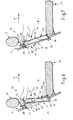
- rear seat backrest partially shown in longitudinal section 11 with headrest 12 and swiveling up (swivel arrow v) and swiveling (swivel arrow u) armrest 13 is conceivable, that the rear seat back 11 a luggage or trunk K of one Rear seat area F separates.
- a holding frame H In the rear seat back 11 is approximately seat-centered with the arm rest 13 aligned, a holding frame H attached.
- the holding frame H adjusts in the rear seat back 11 attached separate one or more parts Component, which is made of appropriate materials, such as out a suitable plastic as an injection molded part or metal as Cast or sheet metal part can be produced. It is also possible that the structure of the rear seat back 11 itself the holding frame H forms.
- the holding frame H defines a through-loading channel D, which connects the trunk K and the rear seat F with each other.
- the holding frame H forms a on the side of the trunk K Loading opening 14 and an installation opening on the side of the rear compartment F 15th
- the holding frame H makes a component approximately rectangular Basic shape with a lower support frame cross leg 16, one upper holding frame cross leg 17 and two in the side Main frame legs held parallel to each other 18 represents
- the through-channel D of the holding frame H is used for detachable purposes
- Mounting receptacle of a mounting frame E which in FIGS. 1-3 both in the side view and in the broad view from Rear seat room is shown.
- the mounting frame E has a lower mounting frame cross leg 19, one of them distanced upwards in parallel distance upper mounting frame cross leg 20 and two laterally in the Mounting frame main legs arranged parallel to each other 21 on.
- the mounting frame E forms in the embodiment shown a ski bag cassette, which (see FIG. 2) has a rear housing cover 22 and a front housing cover 23. Both Housing cover 22, 23 are a double function by means of a enabling actuating button 24 from its locked position detachable, so that when the lids 22, 23 are opened, not shown Way forward spread the ski bag, not shown, in the Rear seat F and then loading the ski bag with skis from the trunk K can be done.
- the actuation button 24 is through a penetration cutout 25 through an actuating pull tab overlaying the actuating button 24 26 to use.
- By pulling the actuating pull tab by hand 26 (see FIG. 2, middle representation) becomes a locking ledge 27 retracted into the upper mounting frame cross member 20.
- the locking bar 27 is a known one Snap lock, which for the locking engagement in a Bolt recess 28 is determined, the inside of the upper holding frame cross leg 17 is arranged.
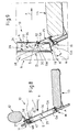
- FIGS. 4-9 each have a bearing recess 29 can be seen, which has a long rectangular end forms narrow end faces 30, 31 limited groove area, in which have a corresponding end counter surfaces 32, 33 strip-like bearing projection 34 of the mounting frame E can intervene.
- the strip-like bearing projection 34 also has a long rectangular one Contour on.
- the long rectangular groove groove 35 of the bearing recess 29 is the installation opening 15, which is arranged in one plane is facing.
- the bearing projections 34 protrude from the lateral outer surfaces 46 of the two mounting frame main legs 21 on each side outwards. Correlating to this are those on the inner surfaces 45 of FIG Holding frame main leg 18 arranged two groove-like Bearing recesses 29 to the center of the holding frame H and to the installation opening 15 open.
- the mounting frame E is gripped by hand at the top its lower area from the installation opening 15 in the Through-loading channel D is inserted until it reaches that of the edge between the lower end counter surface 32 and the long rectangular bar surface 36 formed pivot bearing S of the frame projections 34 on the two Swivel abutment points SW at the bottom in the bearing recesses 29 seated.
- the swivel abutment SW are at the bottom Edges between the long rectangular groove groove base 35 and narrow end surface 30 of the bearing recess 29 is formed (FIG. 4 and 9).
- the in this way between the pivot bearing points S and the swivel axis formed by the swivel abutment points SW is in 1-3 each on the right in the representation of the mounting frame E with Designated SA.
- the mounting frame E becomes corresponding about the swivel axis SA the representations of FIGS. 6-8 as far as that Arrow a pivoted further until that of the lower outer surface of the lower Installation frame cross leg 19 formed stop surface A lies flat against the counter stop surface GA of the holding frame H.
- the counter stop surface GA is from the inner surface of the lower Holding frame cross leg 16 formed.
- the counter stop surface GA diverges after the installation opening 15 away from the center of the holding frame H at an angle ⁇ to the outside. This inclination is the inclination of the stop surface A of the mounting frame E adapted.
- the built-in mounting frame E receives a secure hold when forces in the direction of travel x on it act.
- the holding frame cross leg distanced from the counter stop surface GA 17 forms a flat locking counter-stop 47 which the installed mounting frame E, its displacement approximately parallel preventing installation opening 15, with a stop 48 is applied.
- the surfaces 47 and 48 run approximately parallel to the surfaces GA and A, so that in the upper area of the arrangement a pivoting of the mounting frame E can be done without hindrance.
- FIGS. 2 and 3 differs from the embodiment shown in FIGS. 1 and 4-9 only through a different training of the bearing recesses and Bearing projections.
- the two bearing projections form 40, which laterally from the outer surfaces 46 of the two mounting frame main legs 21 project, approximately corresponding to the Bearing recesses 38 each have a semicircular cross-sectional area bearing journal.
- the two bearing projections 41 (bearing journal) of the mounting frame E has a full circle cross section on.
- the bearing pins 41 are intended to have one each Insertion opening 42 and via an adjoining insertion channel 43 also with a part-circular contact surface 39 provided bearing recesses 44 to be supplied.
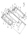
- Figs. 10-13 show that the holding frame H consists of two components consists, namely of a holding frame half facing the rear seat area F. HF and from one facing the luggage or trunk Holding frame half HK.
- the holding frame cross legs of the holding frame H are 16 and 17 and the holding frame main leg of the holding frame H with 18 designated.
- the lower holding frame cross legs are analogous to this of the two holding frame halves HF, HK with 16F, 16K, the upper holding frame cross legs with 17F, 17K and those in parallel distance from each other arranged holding frame main leg designated 18F and 18K.
- the rear seat back 11 is shown in FIGS. 10-13 as a section Seat back structure shown, which facing the rear seat room F Side a console 49 for receiving the armrest 13 and Has plug sleeves 50 for holding the support rods of the headrest 12.
- the opening 51 in the structure of the rear seat back 11 serves the inclusion of the two assembled from the two holding frame halves HF, HK Holding frame H.
- the holding frame halves HF, HK expediently form cast parts made of metal or plastic, in the present case plastic injection molded parts.
- Each holding frame half HF, HK has a sleeve area 52, 53 and a flange area 54, 55.
- the sleeve portion 52 of the the holding frame half HF on the fund side has a larger internal width than the HK sleeve area of the luggage or trunk holding frame half HK.
- Fig. 12 shows that the two holding frame halves HF, HK intermesh telescopically, whereby the holding frame half HF the further outer sleeve region 52 and the Holding frame half HK forms the narrower inner sleeve region 53.
- the two holding frame halves HF, HK are form-fitting to one another attached.
- the upper holding frame cross leg 17K two spigots protruding outwards from the sleeve area 56 integrally formed, which interact with plug openings (plug openings) 57, that on the sleeve region 52 of the upper holding frame cross leg 17F are provided.
- the lower areas of the holding frame halves HF, HK assign their attachment so-called screw domes 68, 69 for receiving Fixing screws, not shown, such as of self-tapping screws, on.
- the upper holding frame cross leg 17K of the holding frame half HK has an approximately long rectangular contour in the sleeve region 53 Pass-through opening 58.
- the through opening 58 corresponds one on the inside of the sleeve area 52 on the upper holding frame cross leg 17F recessed recess with a long rectangular contour 59th
- the passage opening 58 and the recess 59 are for the Passage or for the engagement of those not shown in Figs. 10-13 Lock bar 27 (see. Fig. 1-3) determined.
- the bolt recess 28 of the Strike plate-like component B has an approximately rectangular elongated Basic shape with rounded narrow end areas .
- the Bolt recess 28 of the striking plate-like component B is with the Passage opening 58 of the sleeve region 53 of the holding frame half HK and with the recess 59 of the sleeve region 52 of the holding frame half HF aligned.
- the striking plate-like component B has an approximately L-shaped one Cross-section.
- Component B consists of a bolt recess 28 having locking leg 60 and from an approximately perpendicular to it extending support leg 61. From Figs. 12 and 13 is too see that the bolt leg 60 of the striking plate-like component B in the telescopic joint T between the outer sleeve region 52 of the Holding frame half HF and the inner sleeve portion 53 of the holding frame half HK is arranged.
- the striking plate-like Component B is to be attached by insert mounting and that the narrow end areas of the bolt recess 28 from the reached through two plug pins 56 of the inner sleeve portion 53 and thereby secure their position.
- the holding frame H in Direction x is loaded, the holding frame H is supported by means of Support leg 61 securely on the seat back structure 11. Moreover are transmitted in the event of a crash from the locking bar 27 Forces via the bolt recess 28 of component B also by means of of the support leg 61 to the seat back structure 11 derived.
- the striking plate-like component B has plastically deformable energy absorption zones, which a Crash loading of the transport container device 10 and the vehicle structure 11 prevent or mitigate.
- the arrangement shown also allows it in its lower Area a similar sheet metal component (not shown) with an L-shaped Cross section for additional support of the holding frame H on the To provide structure 11.
- Fig. 11 is the mounting frame E, in the present case a ski bag cassette located.
- the cross section of the mounting frame E is identified as a thick solid black contour (cf. also Fig. 12).
- the mounting frame E is on the top with a passage opening 65 which is approximately rectangular Has contour and which of the inclusion and management of the in 11-13 locking bar 27, not shown (see FIGS. 1 and 3) serves.
- the bearing recesses 38 of the holding frame H and the bearing projections 40 of the mounting frame E correspond to the embodiment 2.
- a die Outer wall of the mounting frame E encompassing seal 66 is arranged on the mounting frame E facing soffit L of the holding frame H .
- the seal 66 is in one between the Sleeve areas 52, 53 formed over the entire inner circumference groove 70 provided in the holding frame.
- the one that adjoins the passage opening 65 Interior 67 of the mounting frame E also serves to accommodate the Actuating mechanism, not shown, for the locking bar 27.
Applications Claiming Priority (4)
| Application Number | Priority Date | Filing Date | Title |
|---|---|---|---|
| DE10042812 | 2000-08-30 | ||
| DE10042812 | 2000-08-30 | ||
| DE10132081 | 2001-07-05 | ||
| DE10132081A DE10132081B9 (de) | 2000-08-30 | 2001-07-05 | Transportbehälter-Einrichtung für Fahrzeuge, wie z.B. Durchladeeinrichtung |
Publications (3)
| Publication Number | Publication Date |
|---|---|
| EP1184224A2 true EP1184224A2 (fr) | 2002-03-06 |
| EP1184224A3 EP1184224A3 (fr) | 2003-07-30 |
| EP1184224B1 EP1184224B1 (fr) | 2006-03-15 |
Family
ID=26006868
Family Applications (1)
| Application Number | Title | Priority Date | Filing Date |
|---|---|---|---|
| EP01119087A Expired - Lifetime EP1184224B1 (fr) | 2000-08-30 | 2001-08-08 | Dispositif à conteneur de transport pour véhicules, p.ex. dispositif à évidement de chargement |
Country Status (4)
| Country | Link |
|---|---|
| US (1) | US6398284B1 (fr) |
| EP (1) | EP1184224B1 (fr) |
| DE (1) | DE50109200D1 (fr) |
| ES (1) | ES2258999T3 (fr) |
Cited By (5)
| Publication number | Priority date | Publication date | Assignee | Title |
|---|---|---|---|---|
| FR2880309A1 (fr) * | 2005-01-05 | 2006-07-07 | Faurecia Sieges Automobile | Agencement d'un dispositif pour transporter des objets encombrants, notamment des skis dans un vehicule, et vehicule comportant un tel agencement |
| DE102006008102B3 (de) * | 2006-02-20 | 2007-05-10 | Grammer Ag | Transportbehälter-Einrichtung mit Arretierungseinrichtung |
| DE102006008101B3 (de) * | 2006-02-20 | 2007-08-02 | Grammer Ag | Rückenlehne eines Fahrzeugsitzes mit modulartigem Einbauteil |
| EP1870286A3 (fr) * | 2006-06-23 | 2008-05-14 | BOS GmbH & Co. KG | Boîte de module verrouillable manuellement |
| CN102101462A (zh) * | 2009-12-18 | 2011-06-22 | F·波尔希名誉工学博士公司 | 机动车辆 |
Families Citing this family (13)
| Publication number | Priority date | Publication date | Assignee | Title |
|---|---|---|---|---|
| US20030085605A1 (en) * | 2001-11-07 | 2003-05-08 | Hentges William J. | Seat and headrest system |
| JP2003191870A (ja) * | 2001-12-27 | 2003-07-09 | Fuji Heavy Ind Ltd | 車両の隔壁ゲート構造 |
| DE10354162A1 (de) * | 2003-11-19 | 2005-06-30 | Bos Gmbh & Co. Kg | Transportbehälter-Einrichtung für Fahrzeuge |
| DE10354160B4 (de) * | 2003-11-19 | 2005-08-25 | Bos Gmbh & Co. Kg | Transportbehälter-Einrichtung für Fahrzeuge |
| DE102004008828B3 (de) * | 2004-02-20 | 2005-08-04 | Bos Gmbh & Co. Kg | Transportbehälter-Einrichtung für Fahrzeuge, wie z.B. Durchlade-Einrichtung, insbesondere für den sitzlehnen- oder kofferraumwandseitigen Einbau in Personenkraftwagen |
| US7152899B2 (en) * | 2005-02-03 | 2006-12-26 | Toyota Technical Center Usa, Inc. | Automotive trunk pass-through for reclining rear seat |
| US7611184B1 (en) * | 2008-07-03 | 2009-11-03 | Ts Tech Co., Ltd. | Vehicular trunk-through openable and closable device |
| DE102009013464C5 (de) * | 2009-03-18 | 2013-09-05 | F.S. Fehrer Automotive Gmbh | Durchladeeinrichtung für ein Fahrzeug |
| US20100325960A1 (en) * | 2009-06-29 | 2010-12-30 | Mcewan John Arthur | System And Method For Closing An Access To A Vehicle |
| JP5530294B2 (ja) * | 2010-07-30 | 2014-06-25 | 日本発條株式会社 | シートバック装置 |
| JP6058934B2 (ja) * | 2012-07-27 | 2017-01-11 | テイ・エス テック株式会社 | リッド装置及びそれを備えたシート装置 |
| JP5959081B2 (ja) * | 2013-02-22 | 2016-08-02 | 株式会社タチエス | 車両用シートのトリムカバーの固定構造及び車両用シート |
| DE102017216555B3 (de) * | 2017-09-19 | 2019-01-31 | Bos Gmbh & Co. Kg | Abdeckvorrichtung für eine Durchladeöffnung eines Fahrzeuginnenraumes |
Citations (2)
| Publication number | Priority date | Publication date | Assignee | Title |
|---|---|---|---|---|
| DE3738931C2 (fr) | 1987-11-17 | 1992-06-11 | Adam Opel Ag, 6090 Ruesselsheim, De | |
| DE29711197U1 (de) | 1997-06-27 | 1998-08-20 | Butz Peter Verwaltung | Transportbehälter-Einrichtung für den Einbau in Kraftfahrzeuge, insbesondere für den sitzlehnenseitigen Einbau in Personenkraftwagen |
Family Cites Families (9)
| Publication number | Priority date | Publication date | Assignee | Title |
|---|---|---|---|---|
| JP3001800B2 (ja) * | 1994-12-12 | 2000-01-24 | 本田技研工業株式会社 | 車両の開閉体 |
| DE3447323A1 (de) * | 1984-12-24 | 1986-06-26 | Eugen Otto 4010 Hilden Butz | Volumenveraenderlicher gepaeckraum im heck von kraftfahrzeugen |
| JPS61193949A (ja) * | 1985-02-21 | 1986-08-28 | Honda Motor Co Ltd | 自動車用リヤ−シ−ト |
| DE9010405U1 (fr) * | 1990-07-10 | 1990-09-20 | Adam Opel Ag, 6090 Ruesselsheim, De | |
| DE4438910C1 (de) * | 1994-11-03 | 1996-03-21 | Butz Peter Verwaltung | Rückhaltevorrichtung für den Laderaum von Kraftfahrzeugen, wie z. B. für Kombinationskraftwagen oder Großraum-Personenkraftwagen |
| DE4438909C1 (de) * | 1994-11-03 | 1996-03-21 | Butz Fahrzeugteile Gmbh | Transportvorrichtung für Kraftfahrzeuge, wie z. B. für Kombinationskraftwagen oder Großraum-Personenkraftwagen |
| DE19519507C2 (de) * | 1995-05-31 | 1997-05-22 | Butz Peter Verwaltung | Transportvorrichtung, wie z. B. für Personen- oder Kombinationskraftwagen, mit einem Behälter für langgestrecktes Ladegut, wie z. B. für Skier |
| DE29803305U1 (de) * | 1998-03-02 | 1998-08-20 | Butz Peter Verwaltung | Sitzanordnung für Fahrzeuge mit einem eine Halterungsaussparung, wie eine Durchladeaussparung einer Durchladeeinrichtung o.dgl. bildenden modulartigen Einbauteil |
| US6076880A (en) * | 1998-04-03 | 2000-06-20 | Lear Automotive Dearborn, Inc | Vehicular seat system and method of folding |
-
2001
- 2001-08-08 EP EP01119087A patent/EP1184224B1/fr not_active Expired - Lifetime
- 2001-08-08 DE DE50109200T patent/DE50109200D1/de not_active Expired - Lifetime
- 2001-08-08 ES ES01119087T patent/ES2258999T3/es not_active Expired - Lifetime
- 2001-08-30 US US09/943,371 patent/US6398284B1/en not_active Expired - Fee Related
Patent Citations (2)
| Publication number | Priority date | Publication date | Assignee | Title |
|---|---|---|---|---|
| DE3738931C2 (fr) | 1987-11-17 | 1992-06-11 | Adam Opel Ag, 6090 Ruesselsheim, De | |
| DE29711197U1 (de) | 1997-06-27 | 1998-08-20 | Butz Peter Verwaltung | Transportbehälter-Einrichtung für den Einbau in Kraftfahrzeuge, insbesondere für den sitzlehnenseitigen Einbau in Personenkraftwagen |
Cited By (6)
| Publication number | Priority date | Publication date | Assignee | Title |
|---|---|---|---|---|
| FR2880309A1 (fr) * | 2005-01-05 | 2006-07-07 | Faurecia Sieges Automobile | Agencement d'un dispositif pour transporter des objets encombrants, notamment des skis dans un vehicule, et vehicule comportant un tel agencement |
| DE102006008102B3 (de) * | 2006-02-20 | 2007-05-10 | Grammer Ag | Transportbehälter-Einrichtung mit Arretierungseinrichtung |
| DE102006008101B3 (de) * | 2006-02-20 | 2007-08-02 | Grammer Ag | Rückenlehne eines Fahrzeugsitzes mit modulartigem Einbauteil |
| EP1870286A3 (fr) * | 2006-06-23 | 2008-05-14 | BOS GmbH & Co. KG | Boîte de module verrouillable manuellement |
| CN102101462A (zh) * | 2009-12-18 | 2011-06-22 | F·波尔希名誉工学博士公司 | 机动车辆 |
| CN102101462B (zh) * | 2009-12-18 | 2013-06-19 | F·波尔希名誉工学博士公司 | 机动车辆 |
Also Published As
| Publication number | Publication date |
|---|---|
| US20020030376A1 (en) | 2002-03-14 |
| EP1184224A3 (fr) | 2003-07-30 |
| DE50109200D1 (de) | 2006-05-11 |
| EP1184224B1 (fr) | 2006-03-15 |
| US6398284B1 (en) | 2002-06-04 |
| ES2258999T3 (es) | 2006-09-16 |
Similar Documents
| Publication | Publication Date | Title |
|---|---|---|
| EP1184224A2 (fr) | Dispositif à conteneur de transport pour véhicules, p.ex. dispositif à évidement de chargement | |
| DE102013000790B4 (de) | Transportvorrichtung zur Befestigung an einem Fahrzeug-Rahmenelement | |
| EP1329355A1 (fr) | Siège modulaire | |
| DE10132081B4 (de) | Transportbehälter-Einrichtung für Fahrzeuge, wie z.B. Durchladeeinrichtung | |
| DE3447323C2 (fr) | ||
| EP2226219B1 (fr) | Système d'un sol de chargement amovible | |
| EP0529288B1 (fr) | Agencement de toit pour véhicule automobile | |
| EP3310593A1 (fr) | Attelage comprenant un manchon de réception | |
| EP0385191B1 (fr) | Toiture amovible pour une plate-forme de chargement d'un véhicule, en particulier pour une fourgonnette | |
| DE3045309A1 (de) | Ruecksitz fuer kraftfahrzeuge mit einer nach vorne umlegbaren rueckenlehne | |
| EP1777103B1 (fr) | Dispositif de vérouillage universel pour container des dimensions différentes sur un véhicule | |
| EP1207078B1 (fr) | Couvercle et/ou dispositif séparateur pour le compartiment de charge ou de bagages d'un véhicule | |
| EP0893306B1 (fr) | Agencement de coffre destiné à être monté dans des véhicules automobiles, en particulier pour être aménagé dans le dossier du siège d'un tel véhicule | |
| EP0831001A1 (fr) | Rancher pour une bache | |
| DE2515955B2 (de) | Motorverkleidung fuer ein fahrzeug | |
| DE102006002783A1 (de) | Vorrichtung zur Halterung von Ladegut | |
| DE19841748A1 (de) | Motorrad mit Behältnis seitlich eines Soziussitzes | |
| EP1566309B1 (fr) | Boîtier de transport pour véhicule pour fixation sur dossier de siège ou paroie intérieur de coffre | |
| EP3372448B1 (fr) | Dispositif de fixation | |
| DE102005018977A1 (de) | Verriegelungseinrichtung für ein ausziehbares Abdeckelement, insbesondere im Gepäckraum eines Kraftfahrzeugs | |
| DE19708395A1 (de) | Vorrichtung zur Befestigung von Kindersitzen | |
| DE2729877A1 (de) | Vorrichtung zur befestigung mindestens eines gegenstandes innerhalb eines fahrgastraumes eines kraftfahrzeuges | |
| EP0492035A1 (fr) | Attelage de remorque, en particulier pour véhicules automobiles | |
| DE102008019396A1 (de) | Laderaum für ein Kraftfahrzeug | |
| DE4304968C2 (de) | Vorrichtung zum Verbinden eines Fahrzeugsitzes mit der Fahrzeugstruktur |
Legal Events
| Date | Code | Title | Description |
|---|---|---|---|
| PUAI | Public reference made under article 153(3) epc to a published international application that has entered the european phase |
Free format text: ORIGINAL CODE: 0009012 |
|
| AK | Designated contracting states |
Kind code of ref document: A2 Designated state(s): AT BE CH CY DE DK ES FI FR GB GR IE IT LI LU MC NL PT SE TR |
|
| AX | Request for extension of the european patent |
Free format text: AL;LT;LV;MK;RO;SI |
|
| PUAL | Search report despatched |
Free format text: ORIGINAL CODE: 0009013 |
|
| AK | Designated contracting states |
Designated state(s): AT BE CH CY DE DK ES FI FR GB GR IE IT LI LU MC NL PT SE TR |
|
| AX | Request for extension of the european patent |
Extension state: AL LT LV MK RO SI |
|
| 17P | Request for examination filed |
Effective date: 20030710 |
|
| RAP1 | Party data changed (applicant data changed or rights of an application transferred) |
Owner name: BOS GMBH & CO. KG |
|
| AKX | Designation fees paid |
Designated state(s): DE ES FR GB IT |
|
| GRAP | Despatch of communication of intention to grant a patent |
Free format text: ORIGINAL CODE: EPIDOSNIGR1 |
|
| GRAS | Grant fee paid |
Free format text: ORIGINAL CODE: EPIDOSNIGR3 |
|
| GRAA | (expected) grant |
Free format text: ORIGINAL CODE: 0009210 |
|
| AK | Designated contracting states |
Kind code of ref document: B1 Designated state(s): DE ES FR GB IT |
|
| REG | Reference to a national code |
Ref country code: GB Ref legal event code: FG4D Free format text: NOT ENGLISH |
|
| GBT | Gb: translation of ep patent filed (gb section 77(6)(a)/1977) |
Effective date: 20060315 |
|
| REF | Corresponds to: |
Ref document number: 50109200 Country of ref document: DE Date of ref document: 20060511 Kind code of ref document: P |
|
| ET | Fr: translation filed | ||
| REG | Reference to a national code |
Ref country code: ES Ref legal event code: FG2A Ref document number: 2258999 Country of ref document: ES Kind code of ref document: T3 |
|
| PLBE | No opposition filed within time limit |
Free format text: ORIGINAL CODE: 0009261 |
|
| STAA | Information on the status of an ep patent application or granted ep patent |
Free format text: STATUS: NO OPPOSITION FILED WITHIN TIME LIMIT |
|
| 26N | No opposition filed |
Effective date: 20061218 |
|
| PGFP | Annual fee paid to national office [announced via postgrant information from national office to epo] |
Ref country code: ES Payment date: 20080820 Year of fee payment: 8 |
|
| PGFP | Annual fee paid to national office [announced via postgrant information from national office to epo] |
Ref country code: IT Payment date: 20080725 Year of fee payment: 8 |
|
| PGFP | Annual fee paid to national office [announced via postgrant information from national office to epo] |
Ref country code: GB Payment date: 20080728 Year of fee payment: 8 |
|
| GBPC | Gb: european patent ceased through non-payment of renewal fee |
Effective date: 20090808 |
|
| REG | Reference to a national code |
Ref country code: ES Ref legal event code: FD2A Effective date: 20090810 |
|
| PG25 | Lapsed in a contracting state [announced via postgrant information from national office to epo] |
Ref country code: GB Free format text: LAPSE BECAUSE OF NON-PAYMENT OF DUE FEES Effective date: 20090808 |
|
| PG25 | Lapsed in a contracting state [announced via postgrant information from national office to epo] |
Ref country code: IT Free format text: LAPSE BECAUSE OF NON-PAYMENT OF DUE FEES Effective date: 20090808 |
|
| PG25 | Lapsed in a contracting state [announced via postgrant information from national office to epo] |
Ref country code: ES Free format text: LAPSE BECAUSE OF NON-PAYMENT OF DUE FEES Effective date: 20090809 |
|
| PGFP | Annual fee paid to national office [announced via postgrant information from national office to epo] |
Ref country code: FR Payment date: 20130828 Year of fee payment: 13 |
|
| REG | Reference to a national code |
Ref country code: FR Ref legal event code: ST Effective date: 20150430 |
|
| PG25 | Lapsed in a contracting state [announced via postgrant information from national office to epo] |
Ref country code: FR Free format text: LAPSE BECAUSE OF NON-PAYMENT OF DUE FEES Effective date: 20140901 |
|
| PGFP | Annual fee paid to national office [announced via postgrant information from national office to epo] |
Ref country code: DE Payment date: 20170629 Year of fee payment: 17 |
|
| REG | Reference to a national code |
Ref country code: DE Ref legal event code: R119 Ref document number: 50109200 Country of ref document: DE |
|
| PG25 | Lapsed in a contracting state [announced via postgrant information from national office to epo] |
Ref country code: DE Free format text: LAPSE BECAUSE OF NON-PAYMENT OF DUE FEES Effective date: 20190301 |