EP1184224A2 - Transport container device for vehicles, e.g. device with loading opening - Google Patents
Transport container device for vehicles, e.g. device with loading opening Download PDFInfo
- Publication number
- EP1184224A2 EP1184224A2 EP01119087A EP01119087A EP1184224A2 EP 1184224 A2 EP1184224 A2 EP 1184224A2 EP 01119087 A EP01119087 A EP 01119087A EP 01119087 A EP01119087 A EP 01119087A EP 1184224 A2 EP1184224 A2 EP 1184224A2
- Authority
- EP
- European Patent Office
- Prior art keywords
- transport container
- holding frame
- container device
- stop
- bearing
- Prior art date
- Legal status (The legal status is an assumption and is not a legal conclusion. Google has not performed a legal analysis and makes no representation as to the accuracy of the status listed.)
- Granted
Links
Images


Classifications
-
- B—PERFORMING OPERATIONS; TRANSPORTING
- B60—VEHICLES IN GENERAL
- B60R—VEHICLES, VEHICLE FITTINGS, OR VEHICLE PARTS, NOT OTHERWISE PROVIDED FOR
- B60R5/00—Compartments within vehicle body primarily intended or sufficiently spacious for trunks, suit-cases, or the like
- B60R5/006—Compartments within vehicle body primarily intended or sufficiently spacious for trunks, suit-cases, or the like stowing or holding means for elongated articles, e.g. skis inside vehicles
Definitions
- the invention relates to a transport container device for vehicles, such as.
- Through-loading device in particular for the seat back or corresponding installation in the trunk wall in passenger cars claim 1.
- Such a transport container device is in the DE 37 38 931 C2 described.
- the known transport container device has one Mounting frame with a flange-like flange forming a stop Edge on which is a counter-stop of a body-side holding frame overlaps.
- the holding frame according to DE 37 38 931 C2 is formed by solid body parts.
- the lower support frame cross leg consists of a body spar, the trapezoidal Cross section tapers towards the top. This body spar forms a swivel abutment on the bracket side.
- the mounting frame of the known device points below a lower saddle-shaped retaining plate on its lower mounting frame cross arm on.
- the well-known mounting frame is used for its installation its saddle-shaped holding plate through the installation opening of the through-channel through to the body spar of trapezoidal cross-section placed.
- Saddle-shaped bracket and trapezoidal Body spars thus form a pivot axis around which the Installation frame can be pivoted into its installation position, in which the flange-like edge, i.e. the stop of the mounting frame, on the holding frame formed by the body-side Counterstop is present.
- This installation position is indicated by a Latch arrangement releasably secured.
- the invention is the Task based, while maintaining the advantageous installation handling to make the transport container device structurally simpler.
- pivot axis extends transversely to the two opposite main legs in one area between two cross legs of both the holding frame and also of the installation frame. It is in the installation situation of the installation frame whose stop is distanced from the swivel axis and the Installation opening facing and also lies on that of the installation opening opposite stop of the holding frame.
- the transport container device requires the two opposite main legs of the mounting frame only one swivel bearing, each on a swivel abutment on the two main legs on the side of the frame attacks.
- the swivel bearing points and which are in engagement with one another Swivel abutment points thus form a kind of mergable Pivot axis. It is therefore not a physical one but about a geometric pivot axis.
- the mounting frame can be pivoted so that distant from the pivot axis and the installation opening facing stop on the counterstop on the holding frame side, facing away from the installation opening. at the same time or subsequently the installation situation of the installation frame is determined by the bolt arrangement distant from the pivot axis is detachable locked, i.e. an unwanted swiveling back of the mounting frame in its removal position is blocked.
- the invention allows any positioning of the pivot axis and also the combination stop of the mounting frame / counter stop of the holding frame.
- a horizontal pivot axis and the stop at the bottom Installation frame cross leg and the counter stop on the have lower support frame cross leg.
- Transport container setup of the mounting frame part or Attachment of any container module or the like can also in the invention Transport container setup of the mounting frame part or Attachment of any container module or the like.
- a practical embodiment preferred for practical purposes consists, however, of the mounting frame as a receiving space at the same time for a folded hose or bag-like transport device, especially for a ski bag.
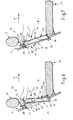
- rear seat backrest partially shown in longitudinal section 11 with headrest 12 and swiveling up (swivel arrow v) and swiveling (swivel arrow u) armrest 13 is conceivable, that the rear seat back 11 a luggage or trunk K of one Rear seat area F separates.
- a holding frame H In the rear seat back 11 is approximately seat-centered with the arm rest 13 aligned, a holding frame H attached.
- the holding frame H adjusts in the rear seat back 11 attached separate one or more parts Component, which is made of appropriate materials, such as out a suitable plastic as an injection molded part or metal as Cast or sheet metal part can be produced. It is also possible that the structure of the rear seat back 11 itself the holding frame H forms.
- the holding frame H defines a through-loading channel D, which connects the trunk K and the rear seat F with each other.
- the holding frame H forms a on the side of the trunk K Loading opening 14 and an installation opening on the side of the rear compartment F 15th
- the holding frame H makes a component approximately rectangular Basic shape with a lower support frame cross leg 16, one upper holding frame cross leg 17 and two in the side Main frame legs held parallel to each other 18 represents
- the through-channel D of the holding frame H is used for detachable purposes
- Mounting receptacle of a mounting frame E which in FIGS. 1-3 both in the side view and in the broad view from Rear seat room is shown.
- the mounting frame E has a lower mounting frame cross leg 19, one of them distanced upwards in parallel distance upper mounting frame cross leg 20 and two laterally in the Mounting frame main legs arranged parallel to each other 21 on.
- the mounting frame E forms in the embodiment shown a ski bag cassette, which (see FIG. 2) has a rear housing cover 22 and a front housing cover 23. Both Housing cover 22, 23 are a double function by means of a enabling actuating button 24 from its locked position detachable, so that when the lids 22, 23 are opened, not shown Way forward spread the ski bag, not shown, in the Rear seat F and then loading the ski bag with skis from the trunk K can be done.
- the actuation button 24 is through a penetration cutout 25 through an actuating pull tab overlaying the actuating button 24 26 to use.
- By pulling the actuating pull tab by hand 26 (see FIG. 2, middle representation) becomes a locking ledge 27 retracted into the upper mounting frame cross member 20.
- the locking bar 27 is a known one Snap lock, which for the locking engagement in a Bolt recess 28 is determined, the inside of the upper holding frame cross leg 17 is arranged.
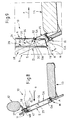
- FIGS. 4-9 each have a bearing recess 29 can be seen, which has a long rectangular end forms narrow end faces 30, 31 limited groove area, in which have a corresponding end counter surfaces 32, 33 strip-like bearing projection 34 of the mounting frame E can intervene.
- the strip-like bearing projection 34 also has a long rectangular one Contour on.
- the long rectangular groove groove 35 of the bearing recess 29 is the installation opening 15, which is arranged in one plane is facing.
- the bearing projections 34 protrude from the lateral outer surfaces 46 of the two mounting frame main legs 21 on each side outwards. Correlating to this are those on the inner surfaces 45 of FIG Holding frame main leg 18 arranged two groove-like Bearing recesses 29 to the center of the holding frame H and to the installation opening 15 open.
- the mounting frame E is gripped by hand at the top its lower area from the installation opening 15 in the Through-loading channel D is inserted until it reaches that of the edge between the lower end counter surface 32 and the long rectangular bar surface 36 formed pivot bearing S of the frame projections 34 on the two Swivel abutment points SW at the bottom in the bearing recesses 29 seated.
- the swivel abutment SW are at the bottom Edges between the long rectangular groove groove base 35 and narrow end surface 30 of the bearing recess 29 is formed (FIG. 4 and 9).
- the in this way between the pivot bearing points S and the swivel axis formed by the swivel abutment points SW is in 1-3 each on the right in the representation of the mounting frame E with Designated SA.
- the mounting frame E becomes corresponding about the swivel axis SA the representations of FIGS. 6-8 as far as that Arrow a pivoted further until that of the lower outer surface of the lower Installation frame cross leg 19 formed stop surface A lies flat against the counter stop surface GA of the holding frame H.
- the counter stop surface GA is from the inner surface of the lower Holding frame cross leg 16 formed.
- the counter stop surface GA diverges after the installation opening 15 away from the center of the holding frame H at an angle ⁇ to the outside. This inclination is the inclination of the stop surface A of the mounting frame E adapted.
- the built-in mounting frame E receives a secure hold when forces in the direction of travel x on it act.
- the holding frame cross leg distanced from the counter stop surface GA 17 forms a flat locking counter-stop 47 which the installed mounting frame E, its displacement approximately parallel preventing installation opening 15, with a stop 48 is applied.
- the surfaces 47 and 48 run approximately parallel to the surfaces GA and A, so that in the upper area of the arrangement a pivoting of the mounting frame E can be done without hindrance.
- FIGS. 2 and 3 differs from the embodiment shown in FIGS. 1 and 4-9 only through a different training of the bearing recesses and Bearing projections.
- the two bearing projections form 40, which laterally from the outer surfaces 46 of the two mounting frame main legs 21 project, approximately corresponding to the Bearing recesses 38 each have a semicircular cross-sectional area bearing journal.
- the two bearing projections 41 (bearing journal) of the mounting frame E has a full circle cross section on.
- the bearing pins 41 are intended to have one each Insertion opening 42 and via an adjoining insertion channel 43 also with a part-circular contact surface 39 provided bearing recesses 44 to be supplied.
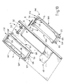
- Figs. 10-13 show that the holding frame H consists of two components consists, namely of a holding frame half facing the rear seat area F. HF and from one facing the luggage or trunk Holding frame half HK.
- the holding frame cross legs of the holding frame H are 16 and 17 and the holding frame main leg of the holding frame H with 18 designated.
- the lower holding frame cross legs are analogous to this of the two holding frame halves HF, HK with 16F, 16K, the upper holding frame cross legs with 17F, 17K and those in parallel distance from each other arranged holding frame main leg designated 18F and 18K.
- the rear seat back 11 is shown in FIGS. 10-13 as a section Seat back structure shown, which facing the rear seat room F Side a console 49 for receiving the armrest 13 and Has plug sleeves 50 for holding the support rods of the headrest 12.
- the opening 51 in the structure of the rear seat back 11 serves the inclusion of the two assembled from the two holding frame halves HF, HK Holding frame H.
- the holding frame halves HF, HK expediently form cast parts made of metal or plastic, in the present case plastic injection molded parts.
- Each holding frame half HF, HK has a sleeve area 52, 53 and a flange area 54, 55.
- the sleeve portion 52 of the the holding frame half HF on the fund side has a larger internal width than the HK sleeve area of the luggage or trunk holding frame half HK.
- Fig. 12 shows that the two holding frame halves HF, HK intermesh telescopically, whereby the holding frame half HF the further outer sleeve region 52 and the Holding frame half HK forms the narrower inner sleeve region 53.
- the two holding frame halves HF, HK are form-fitting to one another attached.
- the upper holding frame cross leg 17K two spigots protruding outwards from the sleeve area 56 integrally formed, which interact with plug openings (plug openings) 57, that on the sleeve region 52 of the upper holding frame cross leg 17F are provided.
- the lower areas of the holding frame halves HF, HK assign their attachment so-called screw domes 68, 69 for receiving Fixing screws, not shown, such as of self-tapping screws, on.
- the upper holding frame cross leg 17K of the holding frame half HK has an approximately long rectangular contour in the sleeve region 53 Pass-through opening 58.
- the through opening 58 corresponds one on the inside of the sleeve area 52 on the upper holding frame cross leg 17F recessed recess with a long rectangular contour 59th
- the passage opening 58 and the recess 59 are for the Passage or for the engagement of those not shown in Figs. 10-13 Lock bar 27 (see. Fig. 1-3) determined.
- the bolt recess 28 of the Strike plate-like component B has an approximately rectangular elongated Basic shape with rounded narrow end areas .
- the Bolt recess 28 of the striking plate-like component B is with the Passage opening 58 of the sleeve region 53 of the holding frame half HK and with the recess 59 of the sleeve region 52 of the holding frame half HF aligned.
- the striking plate-like component B has an approximately L-shaped one Cross-section.
- Component B consists of a bolt recess 28 having locking leg 60 and from an approximately perpendicular to it extending support leg 61. From Figs. 12 and 13 is too see that the bolt leg 60 of the striking plate-like component B in the telescopic joint T between the outer sleeve region 52 of the Holding frame half HF and the inner sleeve portion 53 of the holding frame half HK is arranged.
- the striking plate-like Component B is to be attached by insert mounting and that the narrow end areas of the bolt recess 28 from the reached through two plug pins 56 of the inner sleeve portion 53 and thereby secure their position.
- the holding frame H in Direction x is loaded, the holding frame H is supported by means of Support leg 61 securely on the seat back structure 11. Moreover are transmitted in the event of a crash from the locking bar 27 Forces via the bolt recess 28 of component B also by means of of the support leg 61 to the seat back structure 11 derived.
- the striking plate-like component B has plastically deformable energy absorption zones, which a Crash loading of the transport container device 10 and the vehicle structure 11 prevent or mitigate.
- the arrangement shown also allows it in its lower Area a similar sheet metal component (not shown) with an L-shaped Cross section for additional support of the holding frame H on the To provide structure 11.
- Fig. 11 is the mounting frame E, in the present case a ski bag cassette located.
- the cross section of the mounting frame E is identified as a thick solid black contour (cf. also Fig. 12).
- the mounting frame E is on the top with a passage opening 65 which is approximately rectangular Has contour and which of the inclusion and management of the in 11-13 locking bar 27, not shown (see FIGS. 1 and 3) serves.
- the bearing recesses 38 of the holding frame H and the bearing projections 40 of the mounting frame E correspond to the embodiment 2.
- a die Outer wall of the mounting frame E encompassing seal 66 is arranged on the mounting frame E facing soffit L of the holding frame H .
- the seal 66 is in one between the Sleeve areas 52, 53 formed over the entire inner circumference groove 70 provided in the holding frame.
- the one that adjoins the passage opening 65 Interior 67 of the mounting frame E also serves to accommodate the Actuating mechanism, not shown, for the locking bar 27.
Abstract
Description
Die Erfindung betrifft eine Transportbehälter-Einrichtung für Fahrzeuge,
wie z.B. Durchladeeinrichtung, insbesondere für den sitzlehnenoder
kofferraumwandseitigen Einbau in Personenkraftwagen entsprechend
dem Anspruch 1.The invention relates to a transport container device for vehicles,
such as. Through-loading device, in particular for the seat back or
corresponding installation in the trunk wall in
Eine solche Transportbehälter-Einrichtung ist in der
DE 37 38 931 C2 beschrieben.Such a transport container device is in the
Die bekannte Transportbehälter-Einrichtung weist einen
Einbaurahmen mit einem einen Anschlag bildenden flanschartigen
Rand auf, welcher einen Gegenanschlag eines karosserieseitigen Halterahmens
übergreift. Der Halterahmen gemäß der DE 37 38 931 C2 ist
von festen Karosserieteilen gebildet. Der untere Halterahmen-Querschenkel
besteht aus einem Karosserieholm, dessen trapezförmiger
Querschnitt sich nach oben hin verjüngt. Dieser Karosserieholm bildet
eine halterahmenseitige Schwenkwiderlagerstelle.The known transport container device has one
Mounting frame with a flange-like flange forming a stop
Edge on which is a counter-stop of a body-side holding frame
overlaps. The holding frame according to
Der Einbaurahmen der bekannten Einrichtung weist unterhalb seines unteren Einbaurahmen-Querschenkels ein sattelförmiges Halteblech auf. Zu seinem Einbau wird der bekannte Einbaurahmen mit seinem sattelförmigen Halteblech durch die Einbauöffnung des Durchladekanals hindurch auf den Karosserieholm trapezförmigen Querschnitts aufgesetzt. Sattelförmiges Halteblech und trapezförmiger Karosserieholm bilden so eine Schwenkachse, um die herum der Einbaurahmen in seine Einbauposition hinein geschwenkt werden kann, in welcher der flanschartige Rand, also der Anschlag des Einbaurahmens, an dem vom karosserieseitigen Halterahmen gebildeten Gegenanschlag anliegt. Diese Einbauposition wird durch eine Riegelanordnung lösbar gesichert. The mounting frame of the known device points below a lower saddle-shaped retaining plate on its lower mounting frame cross arm on. The well-known mounting frame is used for its installation its saddle-shaped holding plate through the installation opening of the through-channel through to the body spar of trapezoidal cross-section placed. Saddle-shaped bracket and trapezoidal Body spars thus form a pivot axis around which the Installation frame can be pivoted into its installation position, in which the flange-like edge, i.e. the stop of the mounting frame, on the holding frame formed by the body-side Counterstop is present. This installation position is indicated by a Latch arrangement releasably secured.
Ausgehend von der eingangs beschriebenen Transportbehälter-Einrichtung, welche wegen ihres verschwenkbaren Einbaurahmens bereits einen bequemen raschen Einbau gestattet, liegt der Erfindung die Aufgabe zugrunde, unter Beibehaltung der vorteilhaften Einbauhandhabung die Transportbehälter-Einrichtung baulich einfacher zu gestalten.Starting from the transport container device described at the beginning, which already because of their swiveling installation frame allows a convenient quick installation, the invention is the Task based, while maintaining the advantageous installation handling to make the transport container device structurally simpler.
Diese Aufgabe wird entsprechend der Gesamtheit der Merkmale
des Anspruchs 1 gelöst.This task is done according to the entirety of the characteristics
of
Erfindungsgemäß erstreckt sich die Schwenkachse quer zu den beiden einander gegenüberliegenden Hauptschenkeln in einem Bereich zwischen zwei Querschenkeln jeweils sowohl des Halterahmens als auch des Einbaurahmens. Dabei ist in der Einbausituation des Einbaurahmens dessen Anschlag von der Schwenkachse distanziert und der Einbauöffnung zugewandt und liegt zudem an dem der Einbauöffnung abgewandten Gegenanschlag des Halterahmens an.According to the pivot axis extends transversely to the two opposite main legs in one area between two cross legs of both the holding frame and also of the installation frame. It is in the installation situation of the installation frame whose stop is distanced from the swivel axis and the Installation opening facing and also lies on that of the installation opening opposite stop of the holding frame.
Die vorbeschriebenen erfindungsgemäßen Merkmale bedeuten
eine erhebliche bauliche Vereinfachung, wodurch insbesondere der von
der DE 37 38 931 C2 bekannte untere Halterahmen-Querschenkel trapezförmigen
Querschnitts und das dazu korrespondierende sattelförmige
Blechteil am unteren Einbaurahmen-Querschenkel entbehrlich
sind.The features according to the invention described above mean
a considerable structural simplification, in particular that of
Die erfindungsgemäße Transportbehälter-Einrichtung benötigt an den beiden gegenüberliegenden Hauptschenkeln des Einbaurahmens nur jeweils eine Schwenklagerstelle, welche jeweils an einer Schwenkwiderlagerstelle an den beiden halterahmenseitigen Hauptschenkeln angreift.The transport container device according to the invention requires the two opposite main legs of the mounting frame only one swivel bearing, each on a swivel abutment on the two main legs on the side of the frame attacks.
Die im Eingriff miteinander befindlichen Schwenklagerstellen und Schwenkwiderlagerstellen bilden so eine gewissermaßen zusammenfügbare Schwenkachse. Es handelt sich demnach nicht um eine körperliche sondern um eine geometrische Schwenkachse. The swivel bearing points and which are in engagement with one another Swivel abutment points thus form a kind of mergable Pivot axis. It is therefore not a physical one but about a geometric pivot axis.
Hierdurch kann der Einbaurahmen verschwenkt werden, so dass sich dessen von der Schwenkachse distanzierter und der Einbauöffnung zugewandter Anschlag an den halterahmenseitigen Gegenanschlag, der der Einbauöffnung abgewandt ist, anlegen kann. Zugleich oder nachfolgend wird die Einbausituation des Einbaurahmens durch die von der Schwenkachse distanzierte Riegelanordnung lösbar arretiert, d.h., ein ungewolltes Zurückschwenken des Einbaurahmens in dessen Entnahmeposition wird blockiert.As a result, the mounting frame can be pivoted so that distant from the pivot axis and the installation opening facing stop on the counterstop on the holding frame side, facing away from the installation opening. at the same time or subsequently the installation situation of the installation frame is determined by the bolt arrangement distant from the pivot axis is detachable locked, i.e. an unwanted swiveling back of the mounting frame in its removal position is blocked.
Die Erfindung gestattet jegliche Positionierung der Schwenkachse und auch der Kombination Anschlag des Einbaurahmens/Gegenanschlag des Halterahmens.The invention allows any positioning of the pivot axis and also the combination stop of the mounting frame / counter stop of the holding frame.
Indes wird die bevorzugte erfindungsgemäße Ausführungsform eine horizontale Schwenkachse und den Anschlag an dem unteren Einbaurahmen-Querschenkel sowie den Gegenanschlag an dem unteren Halterahmen-Querschenkel aufweisen.Meanwhile, the preferred embodiment of the present invention a horizontal pivot axis and the stop at the bottom Installation frame cross leg and the counter stop on the have lower support frame cross leg.
Gleichermaßen ist es beispielsweise denkbar, bei Bedarf die Schwenkachse aufrecht zu positionieren und dabei den Anschlag des Einbaurahmens sowie den Gegenanschlag des Halterahmens jeweils einem aufrechten seitlichen Querschenkel zuzuordnen.Likewise, it is conceivable, for example, the To position the swivel axis upright while the stop of the Installation frame and the counter stop of the holding frame in each case to assign an upright lateral cross leg.
Wie von anderen Transportbehälter-Einrichtungen (vgl. z.B. DE-Gebrauchsmuster 297 11 197) bekannt, kann auch bei der erfindungsgemäßen Transportbehälter-Einrichtung der Einbaurahmen Teil oder Anbauteil eines beliebigen Behältermoduls od. dgl. sein.As from other transport container facilities (see e.g. DE utility model 297 11 197) known, can also in the invention Transport container setup of the mounting frame part or Attachment of any container module or the like.
Eine für die Praxis bevorzugte zweckmäßige Ausführungsform besteht indessen darin, den Einbaurahmen zugleich als Aufnahmeraum für eine zusammengefaltete schlauch- oder sackartige Transportvorrichtung, insbesondere für einen Skisack, auszugestalten. A practical embodiment preferred for practical purposes consists, however, of the mounting frame as a receiving space at the same time for a folded hose or bag-like transport device, especially for a ski bag.
In den Zeichnungen sind bevorzugte Ausführungsbeispiele
entsprechend der Erfindung näher dargestellt, es zeigen
Unabhängig von der jeweiligen spezifischen Ausgestaltung einer
Ausführungsform ist jede Transportbehälter-Einrichtung in den Zeichnungen
durchgehend mit der Bezugsziffer 10 versehen.Regardless of the specific design of a
Each transport container device in the drawings is an embodiment
provided with the
Anhand einer teilweise im Längsschnitt dargestellten Fondsitzlehne
11 mit Kopfstütze 12 und heraufschwenkbarer (Schwenkpfeil v)
und herabschwenkbarer (Schwenkpfeil u) Armlehne 13 ist vorstellbar,
dass die Fondsitzlehne 11 einen Gepäck- bzw. Kofferraum K von einem
Fondsitzraum F trennt.Using a rear seat backrest, partially shown in
In der Fondsitzlehne 11 ist, etwa sitzmittig mit der Armlehne 13
ausgerichtet, ein Halterahmen H befestigt. Der Halterahmen H stellt ein
in der Fondsitzlehne 11 befestigtes separates ein- oder mehrteiliges
Bauteil dar, welches aus zweckmäßigen Werkstoffen, wie z.B. aus
einem geeigneten Kunststoff als Spritzgussteil oder auch aus Metall als
Guß- oder Blechformteil hergestellt werden kann. Auch ist es möglich,
dass die Struktur der Fondsitzlehne 11 selbst den Halterahmen H
bildet.In the
Der Halterahmen H begrenzt einen Durchladekanal D, welcher den Kofferraum K und den Fondsitzraum F miteinander verbindet.The holding frame H defines a through-loading channel D, which connects the trunk K and the rear seat F with each other.
Der Halterahmen H bildet an der Seite des Kofferraums K eine Durchladeöffnung 14 und an der Seite des Fondraums F eine Einbauöffnung 15.The holding frame H forms a on the side of the trunk K Loading opening 14 and an installation opening on the side of the rear compartment F 15th
Der Halterahmen H stellt ein Bauteil etwa rechteckförmiger
Grundform mit einem unteren Halterahmen-Querschenkel 16, einem
oberen Halterahmen-Querschenkel 17 sowie mit zwei im seitlichen
Parallelabstand voneinander angeordneten Halterahmen-Hauptschenkeln
18 dar.The holding frame H makes a component approximately rectangular
Basic shape with a lower support
Der Durchladekanal D des Halterahmens H dient der lösbaren Befestigungsaufnahme eines Einbaurahmens E, welcher in den Fig. 1-3 sowohl in der Seitenansicht als auch in der breitflächigen Ansicht vom Fondsitzraum her dargestellt ist.The through-channel D of the holding frame H is used for detachable purposes Mounting receptacle of a mounting frame E, which in FIGS. 1-3 both in the side view and in the broad view from Rear seat room is shown.
Der Einbaurahmen E weist einen unteren Einbaurahmen-Querschenkel
19, einen davon nach oben hin im Parallelabstand distanzierten
oberen Einbaurahmen-Querschenkel 20 sowie zwei seitlich im
Parallelabstand voneinander angeordnete Einbaurahmen-Hauptschenkel
21 auf.The mounting frame E has a lower mounting
Der Einbaurahmen E bildet bei der gezeigten Ausführungsform
eine Skisack-Kassette, welche (s. a. Fig. 2) ein rückwärtigen Gehäusedeckel
22 und einen vorderen Gehäusedeckel 23 aufweist. Beide
Gehäusedeckel 22, 23 sind mittels einer eine Doppelfunktion
ermöglichenden Betätigungstaste 24 aus ihrer Verriegelungslage
lösbar, so dass bei aufgeklappten Deckeln 22, 23 in nicht dargestellter
Weise ein Ausbreiten des nicht gezeigten Skisacks nach vorn in den
Fondsitzraum F hinein und danach ein Beladen des Skisacks mit Skier
vom Kofferraum K her erfolgen kann.The mounting frame E forms in the embodiment shown
a ski bag cassette, which (see FIG. 2) has a
Die Betätigungstaste 24 ist durch eine Durchgriffaussparung 25
hindurch einer die Betätigungstaste 24 überlagernden Betätigungszuglasche
26 zu bedienen. Durch einen Zug von Hand an der Betätigungszuglasche
26 (vgl. Fig. 2 mittlere Darstellung) wird eine Riegelleiste 27
in den oberen Einbaurahmen-Querholm 20 eingefahren.The
Bei der Riegelleiste 27 handelt es sich um einen an sich bekannten
Schnappriegel, welcher für den verriegelnden Eingriff in eine
Riegelaussparung 28 bestimmt ist, die innen am oberen Halterahmen-Querschenkel
17 angeordnet ist.The
Aus den Fig. 1 sowie aus den Fig. 4-9 ist jeweils eine Lageraussparung
29 ersichtlich, welche einen langrechteckigen, endseitig durch
schmale Abschlussflächen 30, 31 begrenzten Kehlnutbereich bildet, in
welchen ein korrespondierende Abschluß-Gegenflächen 32, 33 aufweisender
leistenartiger Lagervorsprung 34 des Einbaurahmens E
eingreifen kann.1 and FIGS. 4-9 each have a
Der leistenartige Lagervorsprung 34 weist ebenfalls eine langrechteckige
Kontur auf. Der langrechteckige Kehlnutgrund 35 der Lageraussparung
29 ist der Einbauöffnung 15, welche in einer Ebene angeordnet
ist, zugewandt.The strip-
Die funktionelle Einbauhandhabung des Einbaurahmens E wird nun für das Ausführungsbeispiel gemäß Fig. 1 an Hand der Fig. 4-9 im einzelnen beschrieben. Diese Beschreibung gilt zugleich grundsätzlich für die in den Fig. 2 und 3 sowie ebenfalls für die in den Fig. 10-13 gezeigten Ausführungsformen.The functional installation handling of the installation frame E is now for the embodiment of FIG. 1 with reference to FIGS. 4-9 in described. This description also applies in principle for those shown in Figs. 2 and 3 and also for those shown in Figs. 10-13 Embodiments.
Die Lagervorsprünge 34 ragen aus den seitlichen Außenflächen
46 von beiden Einbaurahmen-Hauptschenkeln 21 jeweils seitlich
nach außen vor. Dazu korrelierend, sind die an den Innenflächen 45 der
Halterahmen-Hauptschenkel 18 angeordneten beiden kehlnutartigen
Lageraussparungen 29 zur Mitte des Halterahmens H sowie zur Einbauöffnung
15 hin offen.The
Der Einbaurahmen E wird oben mit der Hand ergriffen, mit
seinem unteren Bereich von der Einbauöffnung 15 her in den
Durchladekanal D so weit eingeführt, bis jeweils die von der Kante
zwischen der unteren Abschluß-Gegenfläche 32 und der
langrechteckförmigen Leistenfläche 36 gebildete Schwenklagerstelle S
der eimbaurahmenseitigen Lagervorsprünge 34 auf den beiden
Schwenkwiderlagerstellen SW unten in den Lageraussparungen 29
aufsitzen.The mounting frame E is gripped by hand at the top
its lower area from the
Die Schwenkwiderlagerstellen SW werden jeweils an den unteren
Kanten zwischen dem langrechteckigen Kehlnutgrund 35 und der
schmalen Abschlussfläche 30 der Lageraussparung 29 gebildet (Fig. 4
und 9). Die auf diese Weise zwischen den Schwenklagerstellen S und
den Schwenkwiderlagerstellen SW gebildete Schwenkachse ist u.a. in
den Fig. 1-3 jeweils rechts in der Darstellung des Einbaurahmens E mit
SA bezeichnet. The swivel abutment SW are at the bottom
Edges between the long rectangular
Um die Schwenkachse SA wird der Einbaurahmen E entsprechend
den Darstellungen der Fig. 6-8 so weit entsprechend dem
Pfeil a weitergeschwenkt, bis die von der unteren Außenfläche des unteren
Einbaurahmen-Querschenkels 19 gebildete Anschlagfläche A
flächig an der Gegenanschlagfläche GA des Halterahmens H anliegt.
Die Gegenanschlagfläche GA wird von der Innenfläche des unteren
Halterahmen-Querschenkels 16 gebildet.The mounting frame E becomes corresponding about the swivel axis SA
the representations of FIGS. 6-8 as far as that
Arrow a pivoted further until that of the lower outer surface of the lower
Installation frame
Die Gegenanschlagfläche GA divergiert im Anschluß an die Einbauöffnung
15 von der Mitte des Halterahmens H weg mit einem Winkel
∝ nach außen. Dieser Neigung ist die Neigung der Anschlagfläche A
des Einbaurahmens E angepasst. Der eingebaute Einbaurahmen E
erhält so einen sicheren Halt, wenn Kräfte in Fahrtrichtung x auf ihn
einwirken.The counter stop surface GA diverges after the
Gemäß Fig. 8 ist somit die Einbausituation des Einbaurahmens E
erzielt, welche durch die Riegelleiste 27 am oberen Einbaurahmen-Querschenkel
20 lösbar arretiert ist, die in die Riegelaussparung 28 am
oberen Halterahmen-Querschenkel 17 eingeschnappt ist. Die
Schwenkachse SA befindet sich etwa im unteren Drittel der zusammengefügten
Anordnung H/E.8 is thus the installation situation of the mounting frame E.
achieved by the locking
Der von der Gegenanschlagfäche GA distanzierte Halterahmen-Querschenkel
17 bildet einen flächigen Sperr-Gegenanschlag 47, an
welchem der montierte Einbaurahmen E, seine Verschiebung etwa parallel
zur Einbauöffnung 15 verhindernd, mit einem Sperranschlag 48
anliegt. Die Flächen 47 und 48 verlaufen etwa parallel zu den Flächen
GA und A, so dass im oberen Bereich der Anordnung ein Einschwenken
des Einbaurahmens E behinderungsfrei erfolgen kann.The holding frame cross leg distanced from the counter
Durch Hintergreifen der gestrichelt eingezeichneten Handgriffaussparung
37 der Betätigungszuglasche 26 kann die Riegelleiste 27
wieder in den Einbaurahmen E eingefahren und letzterer sodann in
einer dem Pfeil a entgegengesetzten Schwenkrichtung in einfacher
Weise aus dem Durchladekanal D entnommen werden.By reaching behind the handle recess shown in dashed
Die Ausführungsform entsprechend den Fig. 2 und 3 unterscheidet sich von der in den Fig. 1 sowie 4-9 gezeigten Ausführungsform lediglich durch eine andere Ausbildung der Lageraussparungen und der Lagervorsprünge.The embodiment according to FIGS. 2 and 3 differs differs from the embodiment shown in FIGS. 1 and 4-9 only through a different training of the bearing recesses and Bearing projections.
Gemäß Fig. 2 sind die beiden Lageraussparungen 38 an den
beiden Halterahmen-Hauptschenkeln 18 mittels einer der Einbauöffnung
15 zugewandten teilkreiszylindrischen Anlagefläche 39 etwa
halbkreisförmig konturiert. Hierbei bilden die beiden Lagervorsprünge
40, welche seitlich von den Außenflächen 46 der beiden Einbaurahmen-Hauptschenkel
21 vorstehen, etwa korrespondierend zu den
Lageraussparungen 38 jeweils einen eine Halbkreis-Querschnittsfläche
aufweisenden Lagerzapfen.2, the two bearing
Bei der Ausführungsform gemäß Fig. 3 weisen die beiden Lagervorsprünge
41 (Lagerzapfen) des Einbaurahmens E einen Vollkreis-Querschnitt
auf. Die Lagerzapfen 41 sind dazu bestimmt, über je eine
Einführöffnung 42 und über einen sich daran anschließenden Einführkanal
43 den ebenfalls mit einer teilkreisförmigen Anlagefläche 39
versehenen Lageraussparungen 44 zugeführt zu werden.In the embodiment according to FIG. 3, the two bearing projections
41 (bearing journal) of the mounting frame E has a full circle cross section
on. The bearing pins 41 are intended to have one each
Die Fig. 10-13 zeigen, dass der Halterahmen H aus zwei Bauteilen besteht, nämlich aus einer zum Fondsitzraum F weisenden Halterahmenhälfte HF und aus einer zum Gepäck- bzw. Kofferraum weisenden Halterahmenhälfte HK.Figs. 10-13 show that the holding frame H consists of two components consists, namely of a holding frame half facing the rear seat area F. HF and from one facing the luggage or trunk Holding frame half HK.
Die Halterahmen-Querschenkel des Halterahmens H sind mit 16 und 17 sowie Halterahmen-Hauptschenkel des Halterahmens H mit 18 bezeichnet. Dazu analog sind die unteren Halterahmen-Querschenkel der beiden Halterahmenhälften HF, HK mit 16F, 16K, die oberen Halterahmen-Querschenkel mit 17F, 17K und die im Parallelabstand voneinander angeordneten Halterahmen-Hauptschenkel mit 18F und 18K bezeichnet.The holding frame cross legs of the holding frame H are 16 and 17 and the holding frame main leg of the holding frame H with 18 designated. The lower holding frame cross legs are analogous to this of the two holding frame halves HF, HK with 16F, 16K, the upper holding frame cross legs with 17F, 17K and those in parallel distance from each other arranged holding frame main leg designated 18F and 18K.
Die Fondsitzlehne 11 ist in den Fig. 10-13 als Abschnitt einer
Sitzlehnenstruktur dargestellt, welche an ihrer dem Fondsitzraum F zugewandten
Seite eine Konsole 49 zur Aufnahme der Armlehne 13 und
Steckhülsen 50 zur Halterung der Tragstangen der Kopfstütze 12 aufweist.
Der Durchbruch 51 in der Struktur der der Fondsitzlehne 11 dient
der Aufnahme des aus den beiden Halterahmenhälften HF, HK zusammengefügten
Halterahmens H.The rear seat back 11 is shown in FIGS. 10-13 as a section
Seat back structure shown, which facing the rear seat room F
Side a
Die Halterahmenhälften HF, HK bilden zweckmäßig Gussteile aus Metall oder aus Kunststoff, im vorliegenden Fall Kunststoffspritzgussteile.The holding frame halves HF, HK expediently form cast parts made of metal or plastic, in the present case plastic injection molded parts.
Jede Halterahmenhälfte HF, HK weist einen Hülsenbereich 52,
53 und einen Flanschbereich 54, 55 auf. Der Hülsenbereich 52 der
fondseitigen Halterahmenhälfte HF besitzt eine größere lichte Weite als
der Hülsenbereich HK der gepäck- bzw. kofferraumseitigen Halterahmenhälfte
HK. Fig. 12 zeigt, dass die beiden Halterahmenhälften
HF, HK teleskopierend ineinandergreifen, wobei demnach die Halterahmenhälfte
HF den weiteren äußeren Hülsenbereich 52 und die
Halterahmenhälfte HK den engeren inneren Hülsenbereich 53 bildet.Each holding frame half HF, HK has a
Die beiden Halterahmenhälften HF, HK sind formschlüssig aneinander
befestigt. Hierzu sind dem oberen Halterahmen-Querschenkel
17K zwei aus dem Hülsenbereich nach außen vorragende Steckzapfen
56 angeformt, welche mit Stecköffnungen (Steckdurchbrüchen) 57 zusammenwirken,
die am Hülsenbereich 52 des oberen Halterahmen-Querschenkels
17F vorgesehen sind.The two holding frame halves HF, HK are form-fitting to one another
attached. For this purpose, the upper holding frame
Die unteren Bereiche der Halterahmenhälften HF, HK weisen zu
ihrer Befestigung sogenannte Schraubdome 68, 69 zur Aufnahme von
nicht dargestellten Befestigungsschrauben, wie z.B. von Gewindeschneidschrauben,
auf.The lower areas of the holding frame halves HF, HK assign
their attachment so-called
Der obere Halterahmen-Querschenkel 17K der Halterahmenhälfte
HK weist im Hülsenbereich 53 eine etwa langrechteckig konturierte
Durchgriffsöffnung 58 auf. Der Durchgriffsöffnung 58 entspricht
eine innenseitig des Hülsenbereichs 52 am oberen Halterahmen-Querschenkel
17F eingelassene ebenfalls langrechteckig konturierte Aussparung
59.The upper holding frame
Die Durchgriffsöffnung 58 und die Aussparung 59 sind für den
Durchgriff bzw. für den Eingriff der in den Fig. 10-13 nicht gezeigten
Riegelleiste 27 (vgl. Fig. 1-3) bestimmt.The
Als mit der Riegelleiste 27 unmittelbar zusammenwirkende Riegelaussparung
28 dient indessen ein Durchbruch in einem schließblechartigen
Bauteil B aus Stahlblech. Die Riegelaussparung 28 des
schließblechartigen Bauteils B besitzt eine etwa rechteckige langgestreckte
Grundform mit gerundeten schmalseitigen Endbereichen.. Die
Riegelaussparung 28 des schließblechartigen Bauteils B ist mit der
Durchgriffsöffnung 58 des Hülsenbereichs 53 der Halterahmenhälfte HK
und mit der Aussparung 59 des Hülsenbereichs 52 der Halterahmenhälfte
HF ausgerichtet.As a bolt recess which interacts directly with the locking
Das schließblechartige Bauteil B besitzt einen etwa L-förmigen
Querschnitt. Das Bauteil B besteht aus einem die Riegelaussparung 28
aufweisenden Riegelschenkel 60 und aus einem sich dazu etwa rechtwinklig
erstreckenden Stützschenkel 61. Aus den Fig. 12 und 13 ist zu
ersehen, dass der Riegelschenkel 60 des schließblechartigen Bauteils
B in der Teleskopfuge T zwischen dem äußeren Hülsenbereich 52 der
Halterahmenhälfte HF und dem inneren Hülsenbereich 53 der Halterahmenhälfte
HK angeordnet ist. The striking plate-like component B has an approximately L-shaped one
Cross-section. Component B consists of a
Anhand der Fig. 10-13 ist auch vorstellbar, dass das schließblechartige
Bauteil B im Wege der Einlegemontage anzubringen ist und
dass die schmalseitigen Endbereiche der Riegelaussparung 28 von den
beiden Steckzapfen 56 des inneren Hülsenbereichs 53 durchgriffen und
dadurch lagegesichert sind.10-13 it is also conceivable that the striking plate-like
Component B is to be attached by insert mounting and
that the narrow end areas of the
Im Zusammenhang der Fig. 12 und 13 wird auch deutlich, dass
ein Strukturbereich der Fondsitzlehne 11 zwischen der Stirnfläche 62
des Hülsenbereichs 52 der fondseitigen Halterahmenhälfte HF und der
eine Lastaufnahmefläche 63 bildenden inneren Fläche des Stützschenkels
61 des schließblechartigen Bauteils B angeordnet ist. Die an der
Lastaufnahmefläche 63 anliegende Widerlagerfläche der Sitzlehne 11
ist mit 64 bezeichnet.In connection with FIGS. 12 and 13 it is also clear that
a structural area of the rear seat back 11 between the
Wenn also z.B. im Falle eines Crash, der Halterahmen H in
Fahrtrichtung x belastet wird, stützt sich der Halterahmen H mittels des
Stützschenkels 61 sicher an der Sitzlehnenstruktur 11 ab. Außerdem
werden die im Falle eines Crash von der Riegelleiste 27 übertragenen
Kräfte über die Riegelaussparung 28 des Bauteils B ebenfalls mittels
des Stützschenkels 61 zur Sitzlehnenstruktur 11 hin abgeleitet.So if e.g. in the event of a crash, the holding frame H in
Direction x is loaded, the holding frame H is supported by means of
Dabei ist auch vorstellbar, dass das schließblechartige Bauteil B
plastisch verformbare Energieaufnahmezonen aufweist, welche eine
Crashbelastung der Transportbehälter-Einrichtung 10 und der Fahrzeugstruktur
11 verhindern oder mildern.It is also conceivable that the striking plate-like component B
has plastically deformable energy absorption zones, which a
Crash loading of the
Die gezeigte Anordnung lässt es ebenfalls zu, in deren unterem
Bereich ein ähnliches Blechbauteil (nicht dargestellt) mit L-förmigem
Querschnitt zur zusätzlichen Abstützung des Halterahmens H an der
Struktur 11 vorzusehen.The arrangement shown also allows it in its lower
Area a similar sheet metal component (not shown) with an L-shaped
Cross section for additional support of the holding frame H on the
To provide
In Fig. 11 ist der Einbaurahmen E, im vorliegenden Fall eine Skisack-Kassette
eingezeichnet. Der Querschnitt des Einbaurahmens E ist
als dicke durchgezogene schwarze Kontur kenntlich gemacht (vgl.
ebenfalls Fig. 12). Der Einbaurahmen E ist an seiner Oberseite mit
einer Durchgriffsöffnung 65 versehen, welche eine etwa langrechteckige
Kontur aufweist und welche der Aufnahme und Führung der in
den Fig. 11-13 nicht dargestellten Riegelleiste 27 (vgl. Fig. 1 und 3)
dient.In Fig. 11 is the mounting frame E, in the present case a ski bag cassette
located. The cross section of the mounting frame E is
identified as a thick solid black contour (cf.
also Fig. 12). The mounting frame E is on the top with
a
Die Lageraussparungen 38 des Halterahmens H und die Lagervorsprünge
40 des Einbaurahmens E entsprechen dem Ausführungsbeispiel
gemäß Fig. 2.The bearing recesses 38 of the holding frame H and the bearing
Aus Fig. 12 ist weiterhin zu ersehen, dass an der dem Einbaurahmen
E zugewandten Laibung L des Halterahmens H eine die
Außenwand des Einbaurahmens E umgreifende Dichtung 66
angeordnet ist. Die Dichtung 66 ist in einer zwischen den
Hülsenbereichen 52, 53 gebildeten, über den gesamten Innenumfang
des Halterahmens vorgesehenen Nut 70 angeordnet.From Fig. 12 it can also be seen that on the mounting frame
E facing soffit L of the holding frame H a die
Outer wall of the mounting frame
Der sich an die Durchgriffsöffnung 65 anschließende abgeteilte
Innenraum 67 des Einbaurahmens E dient der Aufnahme der ebenfalls
nicht gezeigten Betätigungsmechanik für die Riegelleiste 27.The one that adjoins the
Claims (39)
Applications Claiming Priority (4)
| Application Number | Priority Date | Filing Date | Title |
|---|---|---|---|
| DE10042812 | 2000-08-30 | ||
| DE10042812 | 2000-08-30 | ||
| DE10132081A DE10132081B9 (en) | 2000-08-30 | 2001-07-05 | Transport container device for vehicles, such as e.g. Durchladeeinrichtung |
| DE10132081 | 2001-07-05 |
Publications (3)
| Publication Number | Publication Date |
|---|---|
| EP1184224A2 true EP1184224A2 (en) | 2002-03-06 |
| EP1184224A3 EP1184224A3 (en) | 2003-07-30 |
| EP1184224B1 EP1184224B1 (en) | 2006-03-15 |
Family
ID=26006868
Family Applications (1)
| Application Number | Title | Priority Date | Filing Date |
|---|---|---|---|
| EP01119087A Expired - Lifetime EP1184224B1 (en) | 2000-08-30 | 2001-08-08 | Transport container device for vehicles, e.g. device with loading opening |
Country Status (4)
| Country | Link |
|---|---|
| US (1) | US6398284B1 (en) |
| EP (1) | EP1184224B1 (en) |
| DE (1) | DE50109200D1 (en) |
| ES (1) | ES2258999T3 (en) |
Cited By (5)
| Publication number | Priority date | Publication date | Assignee | Title |
|---|---|---|---|---|
| FR2880309A1 (en) * | 2005-01-05 | 2006-07-07 | Faurecia Sieges Automobile | Heavy object e.g. ski, transporting device for vehicle, has bag with open and closed ends, and frame with fixing systems, to fix by lock mechanism, which cooperate directly with edge of window delimited by rigid wall in cab interior |
| DE102006008102B3 (en) * | 2006-02-20 | 2007-05-10 | Grammer Ag | Transport container mechanism for fixing in seat back of vehicle seat or vehicle interior, has locking mechanism which has two adjustable bar elements coupled with one another, partly parallel to each other |
| DE102006008101B3 (en) * | 2006-02-20 | 2007-08-02 | Grammer Ag | Back rest for a vehicle seat comprises a modular insert in a loading channel defined by a rectangular holding frame having two inner sides that each have a groove receiving a bearing journal attached to each side surface of the insert |
| EP1870286A3 (en) * | 2006-06-23 | 2008-05-14 | BOS GmbH & Co. KG | Manually lockable module box |
| CN102101462A (en) * | 2009-12-18 | 2011-06-22 | F·波尔希名誉工学博士公司 | Motor vehicle |
Families Citing this family (13)
| Publication number | Priority date | Publication date | Assignee | Title |
|---|---|---|---|---|
| US20030085605A1 (en) * | 2001-11-07 | 2003-05-08 | Hentges William J. | Seat and headrest system |
| JP2003191870A (en) * | 2001-12-27 | 2003-07-09 | Fuji Heavy Ind Ltd | Bulkhead gate structure of vehicle |
| DE10354162A1 (en) * | 2003-11-19 | 2005-06-30 | Bos Gmbh & Co. Kg | Transport container device for vehicles |
| DE10354160B4 (en) * | 2003-11-19 | 2005-08-25 | Bos Gmbh & Co. Kg | Transport container device for vehicles |
| DE102004008828B3 (en) * | 2004-02-20 | 2005-08-04 | Bos Gmbh & Co. Kg | Transporting container device for vehicles has bearing point in region of edge going in first when insertion frame is inserted |
| US7152899B2 (en) * | 2005-02-03 | 2006-12-26 | Toyota Technical Center Usa, Inc. | Automotive trunk pass-through for reclining rear seat |
| US7611184B1 (en) * | 2008-07-03 | 2009-11-03 | Ts Tech Co., Ltd. | Vehicular trunk-through openable and closable device |
| DE102009013464C5 (en) * | 2009-03-18 | 2013-09-05 | F.S. Fehrer Automotive Gmbh | Charging device for a vehicle |
| US20100325960A1 (en) * | 2009-06-29 | 2010-12-30 | Mcewan John Arthur | System And Method For Closing An Access To A Vehicle |
| JP5530294B2 (en) * | 2010-07-30 | 2014-06-25 | 日本発條株式会社 | Seat back device |
| JP6058934B2 (en) * | 2012-07-27 | 2017-01-11 | テイ・エス テック株式会社 | Lid device and seat device provided with the same |
| US9902304B2 (en) * | 2013-02-22 | 2018-02-27 | Tachi-S Co., Ltd. | Vehicle seat trim cover fixing structure and vehicle seat |
| DE102017216555B3 (en) * | 2017-09-19 | 2019-01-31 | Bos Gmbh & Co. Kg | Covering device for a through-opening of a vehicle interior |
Citations (2)
| Publication number | Priority date | Publication date | Assignee | Title |
|---|---|---|---|---|
| DE3738931C2 (en) | 1987-11-17 | 1992-06-11 | Adam Opel Ag, 6090 Ruesselsheim, De | |
| DE29711197U1 (en) | 1997-06-27 | 1998-08-20 | Butz Peter Verwaltung | Transport container device for installation in motor vehicles, in particular for installation on the seat back in passenger cars |
Family Cites Families (9)
| Publication number | Priority date | Publication date | Assignee | Title |
|---|---|---|---|---|
| JP3001800B2 (en) * | 1994-12-12 | 2000-01-24 | 本田技研工業株式会社 | Vehicle opening and closing body |
| DE3447323A1 (en) * | 1984-12-24 | 1986-06-26 | Eugen Otto 4010 Hilden Butz | Baggage space with changeable volume in the rear of motor vehicles |
| JPS61193949A (en) * | 1985-02-21 | 1986-08-28 | Honda Motor Co Ltd | Rear seat for automobile |
| DE9010405U1 (en) * | 1990-07-10 | 1990-09-20 | Adam Opel Ag, 6090 Ruesselsheim, De | |
| DE4438910C1 (en) * | 1994-11-03 | 1996-03-21 | Butz Peter Verwaltung | Restraint device for the hold of motor vehicles, such as. B. for combination cars or large passenger cars |
| DE4438909C1 (en) * | 1994-11-03 | 1996-03-21 | Butz Fahrzeugteile Gmbh | Transport device for motor vehicles, such as. B. for combination cars or large passenger cars |
| DE19519507C2 (en) * | 1995-05-31 | 1997-05-22 | Butz Peter Verwaltung | Transport device, such as. B. for passenger or combination vehicles, with a container for elongated cargo, such as. B. for skis |
| DE29803305U1 (en) * | 1998-03-02 | 1998-08-20 | Butz Peter Verwaltung | Seat arrangement for vehicles with a bracket recess, such as a through-loading recess of a through-loading device or the like. forming module-like installation part |
| US6076880A (en) * | 1998-04-03 | 2000-06-20 | Lear Automotive Dearborn, Inc | Vehicular seat system and method of folding |
-
2001
- 2001-08-08 ES ES01119087T patent/ES2258999T3/en not_active Expired - Lifetime
- 2001-08-08 DE DE50109200T patent/DE50109200D1/en not_active Expired - Lifetime
- 2001-08-08 EP EP01119087A patent/EP1184224B1/en not_active Expired - Lifetime
- 2001-08-30 US US09/943,371 patent/US6398284B1/en not_active Expired - Fee Related
Patent Citations (2)
| Publication number | Priority date | Publication date | Assignee | Title |
|---|---|---|---|---|
| DE3738931C2 (en) | 1987-11-17 | 1992-06-11 | Adam Opel Ag, 6090 Ruesselsheim, De | |
| DE29711197U1 (en) | 1997-06-27 | 1998-08-20 | Butz Peter Verwaltung | Transport container device for installation in motor vehicles, in particular for installation on the seat back in passenger cars |
Cited By (6)
| Publication number | Priority date | Publication date | Assignee | Title |
|---|---|---|---|---|
| FR2880309A1 (en) * | 2005-01-05 | 2006-07-07 | Faurecia Sieges Automobile | Heavy object e.g. ski, transporting device for vehicle, has bag with open and closed ends, and frame with fixing systems, to fix by lock mechanism, which cooperate directly with edge of window delimited by rigid wall in cab interior |
| DE102006008102B3 (en) * | 2006-02-20 | 2007-05-10 | Grammer Ag | Transport container mechanism for fixing in seat back of vehicle seat or vehicle interior, has locking mechanism which has two adjustable bar elements coupled with one another, partly parallel to each other |
| DE102006008101B3 (en) * | 2006-02-20 | 2007-08-02 | Grammer Ag | Back rest for a vehicle seat comprises a modular insert in a loading channel defined by a rectangular holding frame having two inner sides that each have a groove receiving a bearing journal attached to each side surface of the insert |
| EP1870286A3 (en) * | 2006-06-23 | 2008-05-14 | BOS GmbH & Co. KG | Manually lockable module box |
| CN102101462A (en) * | 2009-12-18 | 2011-06-22 | F·波尔希名誉工学博士公司 | Motor vehicle |
| CN102101462B (en) * | 2009-12-18 | 2013-06-19 | F·波尔希名誉工学博士公司 | Motor vehicle |
Also Published As
| Publication number | Publication date |
|---|---|
| ES2258999T3 (en) | 2006-09-16 |
| DE50109200D1 (en) | 2006-05-11 |
| US20020030376A1 (en) | 2002-03-14 |
| US6398284B1 (en) | 2002-06-04 |
| EP1184224B1 (en) | 2006-03-15 |
| EP1184224A3 (en) | 2003-07-30 |
Similar Documents
| Publication | Publication Date | Title |
|---|---|---|
| EP1184224A2 (en) | Transport container device for vehicles, e.g. device with loading opening | |
| EP1329355A1 (en) | Seat module | |
| DE10132081B4 (en) | Transport container device for vehicles, such as e.g. Durchladeeinrichtung | |
| DE3447323C2 (en) | ||
| DE2921703A1 (en) | TRANSPORT DEVICE FOR FASTENING ON A CAR ROOF | |
| EP2226219B1 (en) | System with a removable loading floor | |
| EP0529288B1 (en) | Roof arrangement for motor vehicle | |
| EP3310593A1 (en) | Trailer coupling having a receiving sleeve | |
| EP0385191B1 (en) | Loading space covering device for motor vehicles, especially for estate cars | |
| DE3045309A1 (en) | Rake adjustment on rear seat of car - involves fixed ratchets on side of body and catches on seat back | |
| EP1777103B1 (en) | Universal locking device for containers with different sizes on a vehicle | |
| EP0893306B1 (en) | Boot arrangement for installation in motor vehicles, in particular for the seat back of a motor car | |
| EP0831001A1 (en) | Stanchion for a tarpaulin | |
| DE3901354C2 (en) | ||
| DE19841748A1 (en) | Motorbike with a container on the side of a pillion seat | |
| EP1566309B1 (en) | Vehicle transport box fixable on backseat or on the wall of the boot | |
| EP3372448B1 (en) | Safety device | |
| DE102005018977A1 (en) | Locking device for e.g. luggage compartment, has locking unit rotatable together with bolts from releasing position that releases bolts to locking position that locks bolts, during movement of cover unit | |
| DE19708395A1 (en) | Child's seat fixer for road or air vehicles | |
| DE2729877A1 (en) | Luggage securing frame for car - is clipped to back of rear seat and is adjustable in size | |
| EP0492035A1 (en) | Hitch coupling, specially for motor vehicles | |
| DE102008019396A1 (en) | Loading space for station wagon-passenger car, has adjustable guiding element permanently arranged at each of guide rails for adjustably bearing load base relative to guide rails, where rails are arranged at loading space limitation surface | |
| DE4304968C2 (en) | Device for connecting a vehicle seat to the vehicle structure | |
| DE102015211334A1 (en) | Safety locking device in a motor vehicle and motor vehicle with such a safety locking device | |
| DE102012204160A1 (en) | Transportation box e.g. cooling box installed in motor car, has locking devices attached to free ends of left and right pivotable arms, that are locked to guide rail extending along vehicle longitudinal direction in trunk of motor car |
Legal Events
| Date | Code | Title | Description |
|---|---|---|---|
| PUAI | Public reference made under article 153(3) epc to a published international application that has entered the european phase |
Free format text: ORIGINAL CODE: 0009012 |
|
| AK | Designated contracting states |
Kind code of ref document: A2 Designated state(s): AT BE CH CY DE DK ES FI FR GB GR IE IT LI LU MC NL PT SE TR |
|
| AX | Request for extension of the european patent |
Free format text: AL;LT;LV;MK;RO;SI |
|
| PUAL | Search report despatched |
Free format text: ORIGINAL CODE: 0009013 |
|
| AK | Designated contracting states |
Designated state(s): AT BE CH CY DE DK ES FI FR GB GR IE IT LI LU MC NL PT SE TR |
|
| AX | Request for extension of the european patent |
Extension state: AL LT LV MK RO SI |
|
| 17P | Request for examination filed |
Effective date: 20030710 |
|
| RAP1 | Party data changed (applicant data changed or rights of an application transferred) |
Owner name: BOS GMBH & CO. KG |
|
| AKX | Designation fees paid |
Designated state(s): DE ES FR GB IT |
|
| GRAP | Despatch of communication of intention to grant a patent |
Free format text: ORIGINAL CODE: EPIDOSNIGR1 |
|
| GRAS | Grant fee paid |
Free format text: ORIGINAL CODE: EPIDOSNIGR3 |
|
| GRAA | (expected) grant |
Free format text: ORIGINAL CODE: 0009210 |
|
| AK | Designated contracting states |
Kind code of ref document: B1 Designated state(s): DE ES FR GB IT |
|
| REG | Reference to a national code |
Ref country code: GB Ref legal event code: FG4D Free format text: NOT ENGLISH |
|
| GBT | Gb: translation of ep patent filed (gb section 77(6)(a)/1977) |
Effective date: 20060315 |
|
| REF | Corresponds to: |
Ref document number: 50109200 Country of ref document: DE Date of ref document: 20060511 Kind code of ref document: P |
|
| ET | Fr: translation filed | ||
| REG | Reference to a national code |
Ref country code: ES Ref legal event code: FG2A Ref document number: 2258999 Country of ref document: ES Kind code of ref document: T3 |
|
| PLBE | No opposition filed within time limit |
Free format text: ORIGINAL CODE: 0009261 |
|
| STAA | Information on the status of an ep patent application or granted ep patent |
Free format text: STATUS: NO OPPOSITION FILED WITHIN TIME LIMIT |
|
| 26N | No opposition filed |
Effective date: 20061218 |
|
| PGFP | Annual fee paid to national office [announced via postgrant information from national office to epo] |
Ref country code: ES Payment date: 20080820 Year of fee payment: 8 |
|
| PGFP | Annual fee paid to national office [announced via postgrant information from national office to epo] |
Ref country code: IT Payment date: 20080725 Year of fee payment: 8 |
|
| PGFP | Annual fee paid to national office [announced via postgrant information from national office to epo] |
Ref country code: GB Payment date: 20080728 Year of fee payment: 8 |
|
| GBPC | Gb: european patent ceased through non-payment of renewal fee |
Effective date: 20090808 |
|
| REG | Reference to a national code |
Ref country code: ES Ref legal event code: FD2A Effective date: 20090810 |
|
| PG25 | Lapsed in a contracting state [announced via postgrant information from national office to epo] |
Ref country code: GB Free format text: LAPSE BECAUSE OF NON-PAYMENT OF DUE FEES Effective date: 20090808 |
|
| PG25 | Lapsed in a contracting state [announced via postgrant information from national office to epo] |
Ref country code: IT Free format text: LAPSE BECAUSE OF NON-PAYMENT OF DUE FEES Effective date: 20090808 |
|
| PG25 | Lapsed in a contracting state [announced via postgrant information from national office to epo] |
Ref country code: ES Free format text: LAPSE BECAUSE OF NON-PAYMENT OF DUE FEES Effective date: 20090809 |
|
| PGFP | Annual fee paid to national office [announced via postgrant information from national office to epo] |
Ref country code: FR Payment date: 20130828 Year of fee payment: 13 |
|
| REG | Reference to a national code |
Ref country code: FR Ref legal event code: ST Effective date: 20150430 |
|
| PG25 | Lapsed in a contracting state [announced via postgrant information from national office to epo] |
Ref country code: FR Free format text: LAPSE BECAUSE OF NON-PAYMENT OF DUE FEES Effective date: 20140901 |
|
| PGFP | Annual fee paid to national office [announced via postgrant information from national office to epo] |
Ref country code: DE Payment date: 20170629 Year of fee payment: 17 |
|
| REG | Reference to a national code |
Ref country code: DE Ref legal event code: R119 Ref document number: 50109200 Country of ref document: DE |
|
| PG25 | Lapsed in a contracting state [announced via postgrant information from national office to epo] |
Ref country code: DE Free format text: LAPSE BECAUSE OF NON-PAYMENT OF DUE FEES Effective date: 20190301 |