EP1184097B1 - Windungsleger für aus einer Drahtwalzstrasse kommenden schnellbewegten Walzdraht - Google Patents
Windungsleger für aus einer Drahtwalzstrasse kommenden schnellbewegten Walzdraht Download PDFInfo
- Publication number
- EP1184097B1 EP1184097B1 EP01119489A EP01119489A EP1184097B1 EP 1184097 B1 EP1184097 B1 EP 1184097B1 EP 01119489 A EP01119489 A EP 01119489A EP 01119489 A EP01119489 A EP 01119489A EP 1184097 B1 EP1184097 B1 EP 1184097B1
- Authority
- EP
- European Patent Office
- Prior art keywords
- tube
- outlet
- guide
- fwr
- guide groove
- Prior art date
- Legal status (The legal status is an assumption and is not a legal conclusion. Google has not performed a legal analysis and makes no representation as to the accuracy of the status listed.)
- Expired - Lifetime
Links
Images
Classifications
-
- B—PERFORMING OPERATIONS; TRANSPORTING
- B21—MECHANICAL METAL-WORKING WITHOUT ESSENTIALLY REMOVING MATERIAL; PUNCHING METAL
- B21C—MANUFACTURE OF METAL SHEETS, WIRE, RODS, TUBES, PROFILES OR LIKE SEMI-MANUFACTURED PRODUCTS OTHERWISE THAN BY ROLLING; AUXILIARY OPERATIONS USED IN CONNECTION WITH METAL-WORKING WITHOUT ESSENTIALLY REMOVING MATERIAL
- B21C47/00—Winding-up, coiling or winding-off metal wire, metal band or other flexible metal material characterised by features relevant to metal processing only
- B21C47/02—Winding-up or coiling
- B21C47/10—Winding-up or coiling by means of a moving guide
- B21C47/14—Winding-up or coiling by means of a moving guide by means of a rotating guide, e.g. laying the material around a stationary reel or drum
- B21C47/143—Winding-up or coiling by means of a moving guide by means of a rotating guide, e.g. laying the material around a stationary reel or drum the guide being a tube
-
- B—PERFORMING OPERATIONS; TRANSPORTING
- B21—MECHANICAL METAL-WORKING WITHOUT ESSENTIALLY REMOVING MATERIAL; PUNCHING METAL
- B21C—MANUFACTURE OF METAL SHEETS, WIRE, RODS, TUBES, PROFILES OR LIKE SEMI-MANUFACTURED PRODUCTS OTHERWISE THAN BY ROLLING; AUXILIARY OPERATIONS USED IN CONNECTION WITH METAL-WORKING WITHOUT ESSENTIALLY REMOVING MATERIAL
- B21C47/00—Winding-up, coiling or winding-off metal wire, metal band or other flexible metal material characterised by features relevant to metal processing only
- B21C47/02—Winding-up or coiling
- B21C47/10—Winding-up or coiling by means of a moving guide
- B21C47/14—Winding-up or coiling by means of a moving guide by means of a rotating guide, e.g. laying the material around a stationary reel or drum
Definitions
- the invention relates to a turntable for, from a wire rolling mill coming fast moving wire rod, consisting of a fixed horizontal or vertically mounted drive body and a rotatably connected thereto Pipe holding body, which carries a laying pipe whose pipe entrance the drive body facing, with the axis of rotation aligned and the tube exit is arranged at an axial and radial distance from the pipe end, wherein the Laying pipe the shape of an axially between the pipe inlet and pipe outlet pulled apart Has spiral and the in the center of the drive body in the wire entry introduced wire rod until it exits the pipe exit leads, and wherein in the axial direction behind the pipe holding body, with this rotationsverbundener support body provided with cylindrical outer peripheral surface is arranged on a thread-shaped guide trough is, in whose input opening the pipe outlet of the laying pipe opens, and out whose exit opening is the wire rod coming from the laying tube at his Exit formed into continuously successive circular turns, is stored on a conveying device.
- Winding layers are described in DE-B-129 17 16 and GB-A-1175402 those downstream on the outer peripheral surface of the pipe holding body Cylinder body thread-shaped guide troughs by upstanding Guide walls are formed. Together with an output-adjustable Laying pipe is to be created with this turners the possibility, in addition a better cooling of the emerging from the laying pipe wire rod uniform, perfect shape of the formed wire loops at different To ensure wire thickness and wire qualities.
- the guide grooves are thread-shaped extending two-walled circumferential ruts of a support body, the aufsetzund with its hub on the support shaft of the pipe holding body is connectable with this.
- the guide trough should be achieved that cross-sectional and surface quality the end portion of the continuous and guided wire rod, in particular not affected by thin wires.
- the invention has for its object to avoid this expense and about it In addition, better leadership options for the beginning and end sections of the wire rod.
- This object is achieved in that the distance between the opposite Guide walls of the guide channels, starting from the entrance opening, steadily reduced to form a funnel-like constriction and subsequently, before reaching the middle of the total length of the guide channel to the exit opening is measured continuously expanding.
- the invention further provides, in a course of the total length of Guide trough between entrance opening and exit opening by 360 ° of Scope of the area of continuous reduction of the distance of the guide walls between 0 ° and about 110 ° and the range of continuous expansion in the subsequent 250 °.
- rearward Guide wall of the guide channel can be over 360 ° with constant thread pitch angle arranged on the outer peripheral surface of the cylinder body be while the opposite, front guide wall in the area of 110 ° without thread pitch and in the following range of 250 ° with a thread pitch angle that is greater than the thread pitch angle the rear guide wall.
- funnel-shaped narrowing entrance area and the corresponding funnel-shaped extended Output range is achieved that with one and the same Windungsleger Rolled wires of different thicknesses can be processed, and further, that the frequent whiplash movements of the pipe exit of laying tube inserted into the entrance opening of the guide trough end portion of the continuous wire rod through the walls of the funnel-shaped Constriction braking intercepted and then through the back funnel-shaped widening part of the guide walls reibmindemd up to the exit opening to be led.
- the funnel-shaped constriction catches the emerging from the exit opening of the laying pipe, right now still unguided tip leading and conducting.
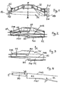
- the supporting body TK consists of a frustoconical Frame SR, which, via the, not shown, tubular holding body driven to the axis indicated by x-x rotates.
- radially outwardly upstanding guide walls FW arranged; These run (see Fig. 2 and 3) in the form of a screw thread.
- These guide walls FW opposite each other form a guide trough FR, with an entrance opening EO and an exit opening AO with 360 ° is guided around the outer peripheral surface AU of the supporting body TK.
- This guide trough FR is by far a dash-dotted lines indicated gutter-shaped Cover AD stationarily arranged.
- a guide wall FWR runs the Guide channel forming guide walls with a constant pitch ⁇ over 360 °, while the other of the guide walls FWV (see also Fig. 4), initially via an initial section AS of the guide channel FR without incline and thereafter via an end portion EA to the exit opening of the Guide groove FR runs with a slope ⁇ , which is greater than the slope ⁇ the opposite rear guide wall FWR.
- the in the direction of the arrow in the input opening EO of the guide trough FR entering wire rod WD is initially funnel-shaped tapered beginning section AS of the guide channel FR, via the subsequent, funnel-shaped widening end portion EA forwarded and guided and after leaving the guide channel FR through the exit opening AO in the form of successive wire rod loops in the direction of the arrow A on a, not shown, further conveying device dropped.
Landscapes
- Engineering & Computer Science (AREA)
- Mechanical Engineering (AREA)
- Winding, Rewinding, Material Storage Devices (AREA)
- Coiling Of Filamentary Materials In General (AREA)
- Guides For Winding Or Rewinding, Or Guides For Filamentary Materials (AREA)
- Manufacture Of Motors, Generators (AREA)
- Metal Extraction Processes (AREA)
- Metal Rolling (AREA)
Description
- Fig. 1
- einen Axialschnitt durch den Tragkörper mit den Führungswänden,
- Fig. 2 und 3
- Seitenansichten des Tragkörpers nach Fig. 1, und
- Fig. 4
- eine Einzelheit der Darstellung nach den Fig. 2 und 3 in vergrößertem Maßstab.
- TK
- Tragkörper
- SR
- (stumpfkegelförmiger) Rahmen
- AU
- Außenumfangsfläche
- FW
- Führungswände
- FR
- Führungsrinne
- FWR
- (rückwärtige) Führungswand
- FWV
- (vordere) Führungswand
- AS
- Anfangsabschnitt
- EA
- Endabschnitt
- EO
- Eingangsöffnung
- AO
- Ausgangsöffnung
- E
- Pfeil
- A
- Pfeil
- WD
- Walzdraht
- α
- (Winkel)
- β
- (Winkel)
Claims (3)
- Windungsleger für aus einer Drahtwalzstraße kommenden schnellbewegten Walzdraht, bestehend aus einem ortsfest horizontal oder vertikal rotierbar gelagerten Antriebskörper und einem, drehfest mit diesem verbundenen Rohrhaltekörper, der ein Legerohr trägt, dessen Rohreneingang, dem Antriebskörper zugewandt, mit dessen Drehachse fluchtet und dessen Rohrausgang mit axialem und radialem Abstand von dem Rohreingang angeordnet ist, wobei das Legerohr in Form einer zwischen Rohreingang und Rohrausgang axial auseinandergezogenen Spirale aufweist und den in der Achsmitte des Antriebskörpers in den Rohreingang eingebrachten Walzdraht bis zu seinem Austritt aus dem Rohrausgang führt, und wobei in Achsrichtung hinter dem Rohrhaltekörper ein, mit diesem rotationsverbundener Tragkörper (TK) mit zylindrischer Außenumfangsfläche (AU) vorgesehen ist, auf der eine gewindeförmig verlaufende Führungsrinne (FR) angeordnet ist, in deren Eingangsöffnung (EU) der Rohrausgang des Legerohres mündet, und aus deren Ausgangsöffnung (AO) der aus dem Legerohr kommende Walzdraht (WD) bei seinem Austritt zu kontinuierlich aufeinanderfolgenden, kreisförmigen Windungen geformt und auf eine Weiterfördereinrichtung abgelegt wird,
dadurch gekennzeichnet, dass der Abstand der einander gegenüberliegenden Führungswände (FW) der Führungsrinne (FR), ausgehend von der Eingangsöffnung (EO) zur Bildung einer trichterartigen Verengung (AS) stetig verkleinernd und anschließend vor Erreichen der Mitte der Gesamtlänge der Führungsrinne (FR) bis zur Ausgangsöffnung (AO) stetig erweiternd bemessen wird. - Windungsleger nach Anspruch 1,
dadurch gekennzeichnet, dass bei einem Verlauf der Gesamtlänge der Führungsrinne (FR) zwischen Eingangsöffnung (EO) und Ausgangsöffnung (AO) um 360° der Bereich (AS) der stetigen Verkleinerung des Abstandes der Führungswände (FWR; FWV) zwischen 0° und etwa 110° und der Bereich der stetigen Erweiterung in dem anschließenden Bereich von 250° liegen. - Windungsleger nach Anspruch 2,
dadurch gekennzeichnet, dass die in Richtung auf die Ausgangsöffnung (AO) gesehen, rückwärtige Führungswand (FWR) der Führungsrinne (FR) über 360° mit einem gleichbleibenden Gewindesteigungswinkel (α) auf der Außenumfangsfläche (AU) des Tragkörpers (TK) angeordnet ist, während die gegenüberliegende, vordere Führungswand (FWV) in dem Bereich AUS) von 110° ohne Gewindesteigungswinkel und in dem folgenden Bereich (EA) von 250° mit einem Gewindesteigungswinkel (β) verläuft, der größer ist als der Gewindesteigungswinkel (α) des Verlaufs der rückwärtigen Führungswand (FWR).
Applications Claiming Priority (2)
| Application Number | Priority Date | Filing Date | Title |
|---|---|---|---|
| DE10043572 | 2000-09-01 | ||
| DE10043572A DE10043572A1 (de) | 2000-09-01 | 2000-09-01 | Windungsleger für aus einer Drahtwalzstraße kommenden schnellbewegten Walzdraht |
Publications (3)
| Publication Number | Publication Date |
|---|---|
| EP1184097A2 EP1184097A2 (de) | 2002-03-06 |
| EP1184097A3 EP1184097A3 (de) | 2002-07-31 |
| EP1184097B1 true EP1184097B1 (de) | 2005-01-19 |
Family
ID=7654955
Family Applications (1)
| Application Number | Title | Priority Date | Filing Date |
|---|---|---|---|
| EP01119489A Expired - Lifetime EP1184097B1 (de) | 2000-09-01 | 2001-08-14 | Windungsleger für aus einer Drahtwalzstrasse kommenden schnellbewegten Walzdraht |
Country Status (4)
| Country | Link |
|---|---|
| US (1) | US6565031B2 (de) |
| EP (1) | EP1184097B1 (de) |
| AT (1) | ATE287301T1 (de) |
| DE (2) | DE10043572A1 (de) |
Families Citing this family (5)
| Publication number | Priority date | Publication date | Assignee | Title |
|---|---|---|---|---|
| RU2224609C1 (ru) * | 2002-07-29 | 2004-02-27 | Некипелов Владимир Станиславович | Способ формирования бунта высокопрочной катанки и устройство для его осуществления |
| JP4278965B2 (ja) * | 2002-11-26 | 2009-06-17 | 旭精機工業株式会社 | 線材成形機 |
| DE102004014264B3 (de) * | 2004-03-24 | 2005-10-27 | Sms Meer Gmbh | Windungsleger für aus einer Drahtwalzstraße kommenden schnell bewegten Walzdraht |
| RU2270730C1 (ru) * | 2004-08-02 | 2006-02-27 | Общество с ограниченной ответственностью "МТ груп" | Способ формирования бунта катанки и устройство для его осуществления |
| US9981297B2 (en) | 2015-01-19 | 2018-05-29 | Russula Corporation | Coil forming laying head system and method of using |
Family Cites Families (6)
| Publication number | Priority date | Publication date | Assignee | Title |
|---|---|---|---|---|
| DE1240025B (de) * | 1965-01-28 | 1967-05-11 | Schloemann Ag | Edenbornhaspel mit senkrechter oder waagerechter Drahtfuehrung |
| DE1285435C2 (de) * | 1966-02-17 | 1973-10-04 | Schloemann Ag | Drehrohrhaspel zum ablegen von draht auf eine foerdereinrichtung |
| FR1526997A (fr) * | 1966-02-17 | 1968-05-31 | Schloemann Ag | Procédé pour former des spires individuelles de fil |
| DD269329A1 (de) * | 1988-03-04 | 1989-06-28 | Thaelmann Schwermaschbau Veb | Walzdrahtleiteinrichtung am windungsleger |
| US5312065A (en) * | 1992-02-05 | 1994-05-17 | Morgan Construction Company | Rod laying head with front and tail end ring control |
| DE19653063A1 (de) * | 1996-12-19 | 1998-06-25 | Schloemann Siemag Ag | Verfahren und Vorrichtung zur Windungslegung von Draht |
-
2000
- 2000-09-01 DE DE10043572A patent/DE10043572A1/de not_active Withdrawn
-
2001
- 2001-08-14 AT AT01119489T patent/ATE287301T1/de active
- 2001-08-14 EP EP01119489A patent/EP1184097B1/de not_active Expired - Lifetime
- 2001-08-14 DE DE50105105T patent/DE50105105D1/de not_active Expired - Lifetime
- 2001-08-31 US US09/945,149 patent/US6565031B2/en not_active Expired - Lifetime
Also Published As
| Publication number | Publication date |
|---|---|
| DE10043572A1 (de) | 2002-03-14 |
| ATE287301T1 (de) | 2005-02-15 |
| US20020047064A1 (en) | 2002-04-25 |
| DE50105105D1 (de) | 2005-02-24 |
| US6565031B2 (en) | 2003-05-20 |
| EP1184097A2 (de) | 2002-03-06 |
| EP1184097A3 (de) | 2002-07-31 |
Similar Documents
| Publication | Publication Date | Title |
|---|---|---|
| DE1291716C2 (de) | Edenbornhaspel mit senkrechter oder waagerechter, vorzugsweise waagerechter drahtfuehrung | |
| DE1400942C3 (de) | Verfahren zum Herstellen einer Zugkabelhülle | |
| DE2727362A1 (de) | Kuehlstrecke zum abkuehlen von stabstahl | |
| DE2558671A1 (de) | Einrichtung zum reduzieren von rohren, insbesondere aus stahl | |
| EP1184097A2 (de) | Windungsleger für aus einer Drahtwalzstrasse kommenden schnellbewegten Walzdraht | |
| DE3403964A1 (de) | Vorrichtung zum oe-friktionsspinnen | |
| DE2822582C3 (de) | Kühlmittelleit- und Walzgutführungseinrichtung für die intermittierende Kühlung von Walzgut, insbesondere von Draht, Feineisen o.dgl. | |
| DE2705521C2 (de) | Vorrichtung zum Ablegen von aus Chemiefasern o.dgl. bestehenden Kabeln im Kannen | |
| DE102004014264B3 (de) | Windungsleger für aus einer Drahtwalzstraße kommenden schnell bewegten Walzdraht | |
| DE656008C (de) | Vorrichtung fuer Verseilmaschinen zum Vorformen der Draehte bzw. Litzen | |
| DE2912162C2 (de) | Vorrichtung zum Windungslegen von Drähten, insbesondere von stark abgekühlten dicken Drähten | |
| EP0655312A1 (de) | Vorrichtung zum Herstellen eines schlauch- oder rohrförmigen Hohlstranges aus thermoplastischem Kunststoff | |
| DE2036040A1 (de) | Vorrichtung zum Aufbringen einer Draht wendel auf ein dünnes Drahtseil | |
| DE19653063A1 (de) | Verfahren und Vorrichtung zur Windungslegung von Draht | |
| EP1048434B1 (de) | Kalibrierhülse mit variabler Durchmessereinstellung | |
| DE3028211A1 (de) | Walzwerk zum streckreduzieren von rohren | |
| DE2152581C3 (de) | Vorrichtung zum Bilden von Windungen aus strangförmigem Gut | |
| DE2344415C2 (de) | Vorrichtung zum Herstellen von mineralisolierten elektrischen Kabeln | |
| DE2513174C3 (de) | Vorrichtung zum Kühlen von Metalldraht | |
| DE1785358A1 (de) | Verfahren und Vorrichtung zur Drehfoerderung von Fasern | |
| DE1254092B (de) | Vorrichtung zum fortlaufenden Umhuellen eines Kunststoff-Draenrohres mit einem Filtermantel | |
| DE1814886C3 (de) | Einrichtung zum kontinuierlichen Aufbringen eines Isoliermantels auf ein biegsames Metallrohr | |
| DE84248C (de) | ||
| DE3230746C2 (de) | Abzugseinrichtung zum Abziehen von kontinuierlich extrudierten Rohren beim Beginn des Extrusionsvorganges | |
| DE2156069C3 (de) | Vorrichtung zum kontinuierlichen Herstellen von flexiblen und verstärkten Rohren aus Kunststoff |
Legal Events
| Date | Code | Title | Description |
|---|---|---|---|
| PUAI | Public reference made under article 153(3) epc to a published international application that has entered the european phase |
Free format text: ORIGINAL CODE: 0009012 |
|
| 17P | Request for examination filed |
Effective date: 20010814 |
|
| AK | Designated contracting states |
Kind code of ref document: A2 Designated state(s): AT BE CH CY DE DK ES FI FR GB GR IE IT LI LU MC NL PT SE TR |
|
| AX | Request for extension of the european patent |
Free format text: AL;LT;LV;MK;RO;SI |
|
| PUAL | Search report despatched |
Free format text: ORIGINAL CODE: 0009013 |
|
| AK | Designated contracting states |
Kind code of ref document: A3 Designated state(s): AT BE CH CY DE DK ES FI FR GB GR IE IT LI LU MC NL PT SE TR |
|
| AX | Request for extension of the european patent |
Free format text: AL;LT;LV;MK;RO;SI |
|
| AKX | Designation fees paid |
Designated state(s): AT BE CH CY DE DK ES FI FR GB GR IE IT LI LU MC NL PT SE TR |
|
| GRAP | Despatch of communication of intention to grant a patent |
Free format text: ORIGINAL CODE: EPIDOSNIGR1 |
|
| GRAS | Grant fee paid |
Free format text: ORIGINAL CODE: EPIDOSNIGR3 |
|
| GRAA | (expected) grant |
Free format text: ORIGINAL CODE: 0009210 |
|
| AK | Designated contracting states |
Kind code of ref document: B1 Designated state(s): AT BE CH CY DE DK ES FI FR GB GR IE IT LI LU MC NL PT SE TR |
|
| PG25 | Lapsed in a contracting state [announced via postgrant information from national office to epo] |
Ref country code: NL Free format text: LAPSE BECAUSE OF FAILURE TO SUBMIT A TRANSLATION OF THE DESCRIPTION OR TO PAY THE FEE WITHIN THE PRESCRIBED TIME-LIMIT Effective date: 20050119 Ref country code: FI Free format text: LAPSE BECAUSE OF FAILURE TO SUBMIT A TRANSLATION OF THE DESCRIPTION OR TO PAY THE FEE WITHIN THE PRESCRIBED TIME-LIMIT Effective date: 20050119 Ref country code: IE Free format text: LAPSE BECAUSE OF FAILURE TO SUBMIT A TRANSLATION OF THE DESCRIPTION OR TO PAY THE FEE WITHIN THE PRESCRIBED TIME-LIMIT Effective date: 20050119 Ref country code: FR Free format text: LAPSE BECAUSE OF NON-PAYMENT OF DUE FEES Effective date: 20050119 Ref country code: TR Free format text: LAPSE BECAUSE OF FAILURE TO SUBMIT A TRANSLATION OF THE DESCRIPTION OR TO PAY THE FEE WITHIN THE PRESCRIBED TIME-LIMIT Effective date: 20050119 |
|
| REG | Reference to a national code |
Ref country code: GB Ref legal event code: FG4D Free format text: NOT ENGLISH |
|
| REG | Reference to a national code |
Ref country code: CH Ref legal event code: EP |
|
| REG | Reference to a national code |
Ref country code: IE Ref legal event code: FG4D Free format text: GERMAN |
|
| REF | Corresponds to: |
Ref document number: 50105105 Country of ref document: DE Date of ref document: 20050224 Kind code of ref document: P |
|
| REG | Reference to a national code |
Ref country code: SE Ref legal event code: TRGR |
|
| PG25 | Lapsed in a contracting state [announced via postgrant information from national office to epo] |
Ref country code: DK Free format text: LAPSE BECAUSE OF FAILURE TO SUBMIT A TRANSLATION OF THE DESCRIPTION OR TO PAY THE FEE WITHIN THE PRESCRIBED TIME-LIMIT Effective date: 20050419 Ref country code: GR Free format text: LAPSE BECAUSE OF FAILURE TO SUBMIT A TRANSLATION OF THE DESCRIPTION OR TO PAY THE FEE WITHIN THE PRESCRIBED TIME-LIMIT Effective date: 20050419 |
|
| PG25 | Lapsed in a contracting state [announced via postgrant information from national office to epo] |
Ref country code: ES Free format text: LAPSE BECAUSE OF FAILURE TO SUBMIT A TRANSLATION OF THE DESCRIPTION OR TO PAY THE FEE WITHIN THE PRESCRIBED TIME-LIMIT Effective date: 20050430 |
|
| GBT | Gb: translation of ep patent filed (gb section 77(6)(a)/1977) |
Effective date: 20050420 |
|
| NLV1 | Nl: lapsed or annulled due to failure to fulfill the requirements of art. 29p and 29m of the patents act | ||
| PG25 | Lapsed in a contracting state [announced via postgrant information from national office to epo] |
Ref country code: LU Free format text: LAPSE BECAUSE OF NON-PAYMENT OF DUE FEES Effective date: 20050814 Ref country code: CY Free format text: LAPSE BECAUSE OF FAILURE TO SUBMIT A TRANSLATION OF THE DESCRIPTION OR TO PAY THE FEE WITHIN THE PRESCRIBED TIME-LIMIT Effective date: 20050814 |
|
| REG | Reference to a national code |
Ref country code: IE Ref legal event code: FD4D |
|
| PG25 | Lapsed in a contracting state [announced via postgrant information from national office to epo] |
Ref country code: CH Free format text: LAPSE BECAUSE OF NON-PAYMENT OF DUE FEES Effective date: 20050831 Ref country code: LI Free format text: LAPSE BECAUSE OF NON-PAYMENT OF DUE FEES Effective date: 20050831 Ref country code: BE Free format text: LAPSE BECAUSE OF NON-PAYMENT OF DUE FEES Effective date: 20050831 Ref country code: MC Free format text: LAPSE BECAUSE OF NON-PAYMENT OF DUE FEES Effective date: 20050831 |
|
| PLBE | No opposition filed within time limit |
Free format text: ORIGINAL CODE: 0009261 |
|
| STAA | Information on the status of an ep patent application or granted ep patent |
Free format text: STATUS: NO OPPOSITION FILED WITHIN TIME LIMIT |
|
| 26N | No opposition filed |
Effective date: 20051020 |
|
| EN | Fr: translation not filed | ||
| REG | Reference to a national code |
Ref country code: CH Ref legal event code: PL |
|
| BERE | Be: lapsed |
Owner name: SMS DEMAG AG Effective date: 20050831 |
|
| PG25 | Lapsed in a contracting state [announced via postgrant information from national office to epo] |
Ref country code: PT Free format text: LAPSE BECAUSE OF NON-PAYMENT OF DUE FEES Effective date: 20050619 |
|
| REG | Reference to a national code |
Ref country code: DE Ref legal event code: R082 Ref document number: 50105105 Country of ref document: DE Representative=s name: HEMMERICH & KOLLEGEN, DE Ref country code: DE Ref legal event code: R081 Ref document number: 50105105 Country of ref document: DE Owner name: SMS GROUP GMBH, DE Free format text: FORMER OWNER: SMS SIEMAG AKTIENGESELLSCHAFT, 40237 DUESSELDORF, DE |
|
| PGFP | Annual fee paid to national office [announced via postgrant information from national office to epo] |
Ref country code: SE Payment date: 20170821 Year of fee payment: 17 |
|
| REG | Reference to a national code |
Ref country code: SE Ref legal event code: EUG |
|
| PG25 | Lapsed in a contracting state [announced via postgrant information from national office to epo] |
Ref country code: SE Free format text: LAPSE BECAUSE OF NON-PAYMENT OF DUE FEES Effective date: 20180815 |
|
| PGFP | Annual fee paid to national office [announced via postgrant information from national office to epo] |
Ref country code: DE Payment date: 20200819 Year of fee payment: 20 Ref country code: GB Payment date: 20200826 Year of fee payment: 20 |
|
| PGFP | Annual fee paid to national office [announced via postgrant information from national office to epo] |
Ref country code: AT Payment date: 20200820 Year of fee payment: 20 Ref country code: IT Payment date: 20200826 Year of fee payment: 20 |
|
| REG | Reference to a national code |
Ref country code: DE Ref legal event code: R071 Ref document number: 50105105 Country of ref document: DE |
|
| REG | Reference to a national code |
Ref country code: GB Ref legal event code: PE20 Expiry date: 20210813 |
|
| REG | Reference to a national code |
Ref country code: AT Ref legal event code: MK07 Ref document number: 287301 Country of ref document: AT Kind code of ref document: T Effective date: 20210814 |
|
| PG25 | Lapsed in a contracting state [announced via postgrant information from national office to epo] |
Ref country code: GB Free format text: LAPSE BECAUSE OF EXPIRATION OF PROTECTION Effective date: 20210813 |