EP1183548B1 - Sonnenfolgevorrichtung - Google Patents
Sonnenfolgevorrichtung Download PDFInfo
- Publication number
- EP1183548B1 EP1183548B1 EP00943667A EP00943667A EP1183548B1 EP 1183548 B1 EP1183548 B1 EP 1183548B1 EP 00943667 A EP00943667 A EP 00943667A EP 00943667 A EP00943667 A EP 00943667A EP 1183548 B1 EP1183548 B1 EP 1183548B1
- Authority
- EP
- European Patent Office
- Prior art keywords
- film
- tracking
- solar
- optical body
- solar element
- Prior art date
- Legal status (The legal status is an assumption and is not a legal conclusion. Google has not performed a legal analysis and makes no representation as to the accuracy of the status listed.)
- Expired - Lifetime
Links
Images


Classifications
-
- F—MECHANICAL ENGINEERING; LIGHTING; HEATING; WEAPONS; BLASTING
- F21—LIGHTING
- F21S—NON-PORTABLE LIGHTING DEVICES; SYSTEMS THEREOF; VEHICLE LIGHTING DEVICES SPECIALLY ADAPTED FOR VEHICLE EXTERIORS
- F21S11/00—Non-electric lighting devices or systems using daylight
-
- F—MECHANICAL ENGINEERING; LIGHTING; HEATING; WEAPONS; BLASTING
- F24—HEATING; RANGES; VENTILATING
- F24S—SOLAR HEAT COLLECTORS; SOLAR HEAT SYSTEMS
- F24S23/00—Arrangements for concentrating solar-rays for solar heat collectors
-
- F—MECHANICAL ENGINEERING; LIGHTING; HEATING; WEAPONS; BLASTING
- F24—HEATING; RANGES; VENTILATING
- F24S—SOLAR HEAT COLLECTORS; SOLAR HEAT SYSTEMS
- F24S23/00—Arrangements for concentrating solar-rays for solar heat collectors
- F24S23/30—Arrangements for concentrating solar-rays for solar heat collectors with lenses
- F24S23/31—Arrangements for concentrating solar-rays for solar heat collectors with lenses having discontinuous faces, e.g. Fresnel lenses
-
- F—MECHANICAL ENGINEERING; LIGHTING; HEATING; WEAPONS; BLASTING
- F24—HEATING; RANGES; VENTILATING
- F24S—SOLAR HEAT COLLECTORS; SOLAR HEAT SYSTEMS
- F24S50/00—Arrangements for controlling solar heat collectors
- F24S50/20—Arrangements for controlling solar heat collectors for tracking
-
- G—PHYSICS
- G02—OPTICS
- G02B—OPTICAL ELEMENTS, SYSTEMS OR APPARATUS
- G02B5/00—Optical elements other than lenses
- G02B5/18—Diffraction gratings
- G02B5/1828—Diffraction gratings having means for producing variable diffraction
-
- G—PHYSICS
- G05—CONTROLLING; REGULATING
- G05D—SYSTEMS FOR CONTROLLING OR REGULATING NON-ELECTRIC VARIABLES
- G05D3/00—Control of position or direction
- G05D3/10—Control of position or direction without using feedback
- G05D3/105—Solar tracker
-
- Y—GENERAL TAGGING OF NEW TECHNOLOGICAL DEVELOPMENTS; GENERAL TAGGING OF CROSS-SECTIONAL TECHNOLOGIES SPANNING OVER SEVERAL SECTIONS OF THE IPC; TECHNICAL SUBJECTS COVERED BY FORMER USPC CROSS-REFERENCE ART COLLECTIONS [XRACs] AND DIGESTS
- Y02—TECHNOLOGIES OR APPLICATIONS FOR MITIGATION OR ADAPTATION AGAINST CLIMATE CHANGE
- Y02E—REDUCTION OF GREENHOUSE GAS [GHG] EMISSIONS, RELATED TO ENERGY GENERATION, TRANSMISSION OR DISTRIBUTION
- Y02E10/00—Energy generation through renewable energy sources
- Y02E10/40—Solar thermal energy, e.g. solar towers
- Y02E10/44—Heat exchange systems
-
- Y—GENERAL TAGGING OF NEW TECHNOLOGICAL DEVELOPMENTS; GENERAL TAGGING OF CROSS-SECTIONAL TECHNOLOGIES SPANNING OVER SEVERAL SECTIONS OF THE IPC; TECHNICAL SUBJECTS COVERED BY FORMER USPC CROSS-REFERENCE ART COLLECTIONS [XRACs] AND DIGESTS
- Y02—TECHNOLOGIES OR APPLICATIONS FOR MITIGATION OR ADAPTATION AGAINST CLIMATE CHANGE
- Y02E—REDUCTION OF GREENHOUSE GAS [GHG] EMISSIONS, RELATED TO ENERGY GENERATION, TRANSMISSION OR DISTRIBUTION
- Y02E10/00—Energy generation through renewable energy sources
- Y02E10/40—Solar thermal energy, e.g. solar towers
- Y02E10/47—Mountings or tracking
Definitions
- the invention relates to a diffractive and / or refractive optical Device with the features of the preamble of claim 1.
- optical body is designed as Fresnel cylindrical lenses, which in a Glass roofing of a glass roof construction are integrated.
- the glass covering with the Fresnel cylindrical lenses is installed stationary on the roof.
- Under the roof absorbers are arranged below this optical body.
- a sunbeam concentrator is known, the one has formed as a prism body on the entrance surface and on the Reflection surface each shows a material layer with a hologram structure.
- the parameters of the hologram structure are chosen so that the radiation with Help the hologram into the prism and so inside the prism is guided that it emerges in a focused manner on several end faces of the prism.
- There is a concentration of radiation and at the same time one Division into the different spectral ranges with concentration of the different spectral ranges on the different beam exit surfaces. In this way, photo transducers specific to the respective spectral range should can be loaded.
- This one consisting of prisms Sun beam concentrator has the disadvantages described above in one Tracking on. Furthermore, shadow effects occur due to the prisms reduce the turnover rate.
- a sun beam concentrator is known, which in Form of a hologram of a light point source is executed.
- the focus the hologram lens turns out to be so large that a Receiver for concentrated radiation at the focal point of the lens Receiver with the lens connecting auxiliary device is required.
- DE 30 12 500 A1 describes a retroreflector for use in Light barriers and light curtains known.
- the reflector used Diffraction gratings made by holographic processes in one photosensitive material are formed.
- the reflector When the reflector is illuminated, the radiation striking it becomes reflected and focused outside the reflector plate with the hologram.
- the invention has for its object an optical device with a Sun following film with a compensation of the over several days changing sun position, in particular with a compensation of to create seasonal sun position.
- the slide can do this for the individual days of a year or half-year have assignable areas, preferably 365 or 182 or 183 different areas.
- spectra-specific solar cells are used.
- There can be several spectrum-specific solar cells are arranged side by side and the individual light spectra are supplied to the respective solar cells.
- the tracking device can be used as Foil transport device with at least one receiving the foil and / or dispensing film storage device, preferably drum, be trained.
- a first drum is provided which Film wound up during rewinding, and a second drum that the Unwinds film during the tracking. It is between the first and second drum a film section preferably arranged tensioned the respectively effective section of the light guide and / or light concentrator device having.
- the first drum is over one for tracking motor drive rotatably driven.
- the second drum runs synchronously With.
- first one Transport device provided that the optical body along its Main extension moved.
- second transport device be provided that the optical body at an angle, preferably at right angles, moved to its main extension or by one to its main extension parallel axis rotated.
- the first or the second transport device is controlled depending on the time of day, i.e. depending on that time of day sun position.
- the other transport device depends on controlled according to the season, i.e. depending on the seasonal position of the sun.
- the diffractive and / or refractive and / or holographic areas having body of the optical device preferably has a flat Light entry surface and a likewise preferably flat light exit surface on.
- Sunlight strikes the light entrance surface at a certain angle of incidence depending on the current position of the light source relative to the receiver, i.e. in solar systems depending on the position of the sun.
- the incident light shines through the body and is redirected or concentrated so that the light at a certain angle or angle Concentration at the light exit surface emerges from the body and so the Receiver is fed.
- the optical parameters of the body are like this chosen that the required angle of failure or the desired concentration is obtained.
- the optical parameters of the body are designed so that the drop angle required for optimal use of sunlight the body and the corresponding angle of incidence on the solar element, possible angle of incidence 90 ° or that maximum concentration is obtained.
- the different sections of the optical parameters optical body can on or in the body in the tracking direction be arranged side by side, the sections being continuous merging sections or as separate discrete sections can be trained. With continuous transition of the sections there are advantages to continuous tracking. Special advantages in this regard, if the variation of the optical parameters in Tracking direction is also formed continuously with a constant course.
- the optical body or the film has at least one layer-shaped area with a redirecting light and / or concentrating structure.
- the optical body can with holographic elements, e.g. can the body preferably have a layered area, the hologram structure having.
- the different sections with regard to the optical parameters can be realized in that the sections are different Have hologram structure.
- the optical body can be a structure of a diffractive lens or a Diffractive mirror to essentially concentrate the light.
- the optical body or the film can face the light source Anti-reflective side.
- the body can be designed as a rigid or flexible body. Special There are advantages when using a holographic film.
- the Film can also be used as a concentrator film with a diffractive lens or structure a diffractive mirror.
- the film can be several in Areas of tracking arranged one behind the other Have lens structure or different mirror structure.
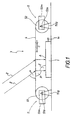
- the solar system in FIG. 1 has a solar element 1.
- the solar element 1 can be a single battery or a battery from side by side arranged solar elements act.
- the solar element 1 can as trained photovoltaic solar cell or heat-generating solar collector his.
- the sunlight 2 radiated onto the solar element 1 is replaced by the Solar element 1 converted into electrical or thermal energy. This is at the output 1a of the solar elements in a network or not shown fed an energy storage.
- the solar element 1 is assigned an optical device 3, which depending on the position of the sun at sunlight angle ⁇ 2 each as perpendicular as possible to the surface of the solar element 1 in order to Use sunlight as efficiently as possible.
- the optical device 3 has a diffractive and / or refractive effect optical body 4, which is irradiated by the sunlight and thereby deflects the sunlight.
- the optical body 4 formed as a transparent holographic film with Distance is stretched over the surface of the solar element 1.
- the hologram structure of the arranged above the solar element Radiated section of the film 4 is formed so that the angle ⁇ Sunlight falling on the surface of the film 4 when passing through the film is redirected and at an angle ⁇ on the underside of the film exit.
- the optical device 3 has a tracking device 5, with which the film 4 relative to the fixedly arranged solar element 1 Sun position is tracked.
- the tracking device 5 has two synchronously driven drums 51, 52.
- the drums 51, 52 are with mutual distance arranged parallel to each other. They are in each case stationary bearing blocks 51g, 52g rotatably mounted. Between Drums 51, 52, the film 4 is stretched, the two opposite ends of the film 4 wound on the drums 51, 52 are.
- the drums 51, 52 are driven by motor control so that they rotate synchronously about its drum axis 51a, 52a.
- the direction of rotation in Figure 1 is clockwise, so that the between the drums 51, 52nd stretched film 4 is transported in the direction C from left to right.
- the Transport speed depends on the course of the day Controlled sun position.
- the film 4 runs continuously in the direction of C.
- the film is wound onto the drum 52 and from the drum 51 settled. Only the one in the tensioned section above the solar element 1 currently present film section is from the incident sunlight shines through and only this section is currently effective.
- the film 4 has along its main extent, i.e. in the surface direction and thus a varying hologram structure in tracking direction C.
- the variation of the parameters of the hologram structure is chosen so that with a a certain predetermined transport or tracking speed continuous adjustment of the light deflection to that of the sun dependent angle of incidence ⁇ is obtained.
- the adjustment of the The hologram structure is designed in such a way that the angle of failure ⁇ at that of The angle of incidence depending on the position of the sun is almost constant over the day is. This means that the angles ⁇ and are approximately constant and therefore sunlight at every position of the sun is used equally efficiently.
- the film level is one direction C parallel to the surface of the solar element arranged pivot axis preferably pivoted together with the drums 51, 52.
- the drums 51, 52 over a not shown e.g. in the Area of the bearing blocks 51g, 52g arranged pivot mechanism be adjusted accordingly at an angle.
- the rotary drive of the drums 51, 52 to that described above daily adjustment of the film in direction C takes place via separate Drive motors 51m, 52m.
- the drive motor 51m drives the drum shaft 51a.
- the output shaft of the drive motor 51m not shown coupled to the drum shaft 51a via a gear, not shown.
- the drive motor 52m drives the drum shaft 52a.
- the two motors 51m, 52m are controlled synchronously.
- the control is like this designed that the transport speed, i.e. the tracking of the slide 4 in direction C depending on the course of the time of day sun he follows.
- the film is put back at night. This happens because the Drive motors run back in the opposite direction and the film from the drum 52 unwound and wound on the drum 51.
- the swiveling movement of the required for seasonal tracking Drums 51, 52 can also be motorized via a not shown Drive motor, which corresponds to the pivot mechanism explained above actuated in a controlled manner.
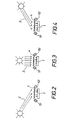
- FIGS. 5 and 6 The exemplary embodiment in FIGS. 5 and 6 is also concerned around a solar system with a diffractive guided over a solar element 1 Foil 4, which by winding and unwinding with a tracking device 5 only schematically indicated, actually much larger and in appropriate distance from each other drums 51, 52 the daytime sun position is tracked.
- film 4 is a film concentrating the incident sunlight. It is a film concentrator in the form of a diffractive lens 4a.
- the incident sunlight is passed through the lens 4a concentrated so that the image of the sun is in the focal point Solar element 1 appears.
- the distance from film 4 to surface A of Solar element is when using a film with a lens diameter of 1 up to 5 cm at 10 to 20 cm.
- the film 4 stretched over the solar element 1 is through during the day the tracking device 5 shifted from left to right in the figures, i.e. along east-west direction. This will make the image of the course of the During the day, depending on the time of day, the sun is more or less inclined following the sun, so that the whole day Image of the sun falls on the solar element 1 arranged in a constant position.
- Figure 5 shows the position with approximately perpendicular sunlight Noon.
- Figure 6 shows the position in the case of obliquely incident sunlight Afternoon. As can be seen in FIG. 6, the film 4 is in this position or track the lens 4a by shifting to the right.
- the transport speed of the film 4 for daily tracking is f x 0.25 per hour, where "f" is the focal length of the lens. So that will the one that occurs due to the time of day of the position of the sun Change in the angle of incidence, which is approximately 15 ° per hour, is taken into account and get an exact time of day tracking.
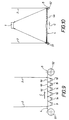
- FIG. 7 shows one such an arrangement of two solar elements 1a, 1b.
- the one about the solar elements 1a, 1b stretched film 4 has two in the direction of movement C of the film lenses 4a, 4b arranged one behind the other.
- lens 4a is solar element 1a
- lens 4b is solar element 1b assigned by the lens 4a the solar element 1a and the lens 4b Illuminated solar element 1b.
- the distance s of the solar elements 1a, 1b equal to the distance between the central axes of the lenses 4a, 4b.
- FIG. 8 shows a film section with a grid arrangement on the film arranged lenses 4a, 4b, 4c.
- the lenses are perpendicular to each other longitudinal and transverse rows arranged side by side. It is this grid arrangement by an angle of approx. 0.25 ° against the movement and direction of extension C of the film 4 rotated.
- the angle of 0.25 ° corresponds to the daily change in the inclination of the sun against that solar panel; this change in angle is 47 ° / 182 per day. That way the daily change in inclination of the sun only by shifting the Film in direction C, i.e. can be compensated without additional adjustment.
- FIG. 9 shows the use of this film 4 in a solar system.
- the Foil is over the solar elements 1a to 1f arranged in a grid arrangement stretched and is opened in the direction of C, along the east-west direction settled.
- the time of day is updated as with the previous embodiments by moving the film during of the day, from left to right in Figure 9. This remains over the entire
- a lens is always assigned to a specific solar element, see above that the solar element is illuminated by this lens.
- the film is moved every day by a lens distance shifted so that each solar element only one day from a lens is illuminated. The next day, the solar element is illuminated by the next lens.
- the tracking takes place when the film moves in Direction C forcibly due to the rotated by the angle of 0.25 ° Grid arrangement. Because the grid arrangement rotated in this way also the daily change in the seasonal height of the sun above Horizon a relative offset of the lenses perpendicular to the direction of propagation achieved and thus compensated for the seasonal change in sun position.
- the seasonal tracking also by swiveling the film level around the Movement axis of the sliding movement take place or by moving the Foil in an inclined towards the horizontal, facing the sun Level.
- the solar element is arranged on the one facing the sun
- Seasonal tracking is thus carried out on the sloping roof of a house Move the film up or down parallel to the sloping roof.
- the film 4 instead of the diffractive lens a diffractive mirror, concave mirror 4s, on.
- f focal length
- Die Mirror film can also have multiple mirrors 4s in longitudinal and transverse rows have arranged.
- the film can be constructed accordingly like that in connection with the exemplary embodiments of FIGS. 5 to 9 described films with a lens structure. With the mirror films are to the Figures 4 to 9 analog embodiments possible.
- the height profile of those used in the exemplary embodiments described diffractive lenses and mirrors consist of concentric zones with spherical and paraboloid cross sections.
- the foils 4 can also have transverse structures in these concentric structures exhibit.
- the foils can simultaneously concentrate and redirect light Act.
Landscapes
- Engineering & Computer Science (AREA)
- Physics & Mathematics (AREA)
- Life Sciences & Earth Sciences (AREA)
- Sustainable Development (AREA)
- General Engineering & Computer Science (AREA)
- Sustainable Energy (AREA)
- Thermal Sciences (AREA)
- Chemical & Material Sciences (AREA)
- Combustion & Propulsion (AREA)
- Mechanical Engineering (AREA)
- General Physics & Mathematics (AREA)
- Automation & Control Theory (AREA)
- Optics & Photonics (AREA)
- Photovoltaic Devices (AREA)
- Diffracting Gratings Or Hologram Optical Elements (AREA)
- Separation Of Suspended Particles By Flocculating Agents (AREA)
- Seal Device For Vehicle (AREA)
- Photometry And Measurement Of Optical Pulse Characteristics (AREA)
- Cookers (AREA)
- Mounting And Adjusting Of Optical Elements (AREA)
- Vibration Dampers (AREA)
- Lock And Its Accessories (AREA)
- Fluid-Damping Devices (AREA)
- Non-Portable Lighting Devices Or Systems Thereof (AREA)
- Diaphragms For Electromechanical Transducers (AREA)
- Traffic Control Systems (AREA)
Applications Claiming Priority (3)
| Application Number | Priority Date | Filing Date | Title |
|---|---|---|---|
| DE19924783A DE19924783C2 (de) | 1999-05-29 | 1999-05-29 | Optische Einrichtung |
| DE19924783 | 1999-05-29 | ||
| PCT/DE2000/001778 WO2000073810A1 (de) | 1999-05-29 | 2000-05-26 | Sonnenfolgevorrichtung |
Publications (2)
| Publication Number | Publication Date |
|---|---|
| EP1183548A1 EP1183548A1 (de) | 2002-03-06 |
| EP1183548B1 true EP1183548B1 (de) | 2003-05-07 |
Family
ID=7909682
Family Applications (1)
| Application Number | Title | Priority Date | Filing Date |
|---|---|---|---|
| EP00943667A Expired - Lifetime EP1183548B1 (de) | 1999-05-29 | 2000-05-26 | Sonnenfolgevorrichtung |
Country Status (12)
| Country | Link |
|---|---|
| US (1) | US6923174B1 (enExample) |
| EP (1) | EP1183548B1 (enExample) |
| JP (1) | JP4574917B2 (enExample) |
| CN (1) | CN1236324C (enExample) |
| AT (1) | ATE239922T1 (enExample) |
| AU (1) | AU767224B2 (enExample) |
| BR (1) | BR0011032A (enExample) |
| DE (3) | DE19924783C2 (enExample) |
| ES (1) | ES2199167T3 (enExample) |
| HK (1) | HK1040772B (enExample) |
| PT (1) | PT1183548E (enExample) |
| WO (1) | WO2000073810A1 (enExample) |
Families Citing this family (29)
| Publication number | Priority date | Publication date | Assignee | Title |
|---|---|---|---|---|
| US6396239B1 (en) * | 2001-04-06 | 2002-05-28 | William M. Benn | Portable solar generator |
| DE102004005050A1 (de) * | 2004-01-30 | 2005-08-25 | Detlef Schulz | Verfahren zur Energieumwandlung solarer Strahlung in elektrischen Strom und Wärme mit farbselektiven Interferenzfilterspiegeln und eine Vorrichtung eines Konzentrator-Solarkollektors mit farbselektiven Spiegeln zur Anwendung des Verfahrens |
| DE102004043556A1 (de) * | 2004-09-09 | 2006-03-30 | Fraunhofer-Gesellschaft zur Förderung der angewandten Forschung e.V. | Solarkollektor mit transluzenter Abdeckung |
| US20110094503A1 (en) * | 2005-03-25 | 2011-04-28 | Jones Dale G | Method and apparatus for solar panel tracking |
| DE202005005631U1 (de) * | 2005-04-08 | 2006-08-17 | ZAE Bayern Bayerisches Zentrum für angewandte Energieforschung e.V. | Sonnenkollektor |
| CN100368831C (zh) * | 2006-03-16 | 2008-02-13 | 曹国斌 | 一种采聚太阳能的掩模片及采用掩模片的太阳能装置 |
| US20080257400A1 (en) * | 2007-04-17 | 2008-10-23 | Mignon George V | Holographically enhanced photovoltaic (hepv) solar module |
| US20080295825A1 (en) * | 2007-06-01 | 2008-12-04 | Jurgen Kleinwachter | Focal width correcting lens system for concentrating sunlight |
| KR101455892B1 (ko) * | 2007-09-10 | 2014-11-04 | 반얀 에너지, 인크 | 광 에너지의 집광, 집결 및 조명을 위한 소형 광소자 |
| CN101918868B (zh) * | 2007-11-08 | 2014-09-24 | 太阳能技术公司 | 光集中器结构和方法 |
| DE102008049538A1 (de) * | 2008-09-30 | 2010-04-22 | Christian Gruba | Lichtbündelungphotovoltaikanlage mit Flüssigkeitskühlung und Nutzung der thermischen Solarenergie (LPS-Anlage) |
| DE102008057387A1 (de) * | 2008-11-14 | 2010-05-20 | Tobias Kiesewetter | Solaranlage mit optischer Einrichtung |
| US8162495B2 (en) * | 2009-02-03 | 2012-04-24 | Steven Russell Green | System and method of focusing electromagnetic radiation |
| US20110000478A1 (en) * | 2009-07-02 | 2011-01-06 | Dan Reznik | Camera-based heliostat tracking controller |
| CN101661292B (zh) * | 2009-09-18 | 2011-06-01 | 中国科学院安徽光学精密机械研究所 | 一种反射式太阳红外辐射动态光路跟踪系统 |
| US20110088684A1 (en) * | 2009-10-16 | 2011-04-21 | Raja Singh Tuli | Solar Energy Concentrator |
| GB2476657A (en) * | 2009-12-30 | 2011-07-06 | Luke Anthony William Robinson | Solar energy collection apparatus |
| FR2966917A1 (fr) * | 2010-10-29 | 2012-05-04 | Axiosun | Concentrateur de rayonnement solaire. |
| PL2674690T3 (pl) | 2011-02-11 | 2019-06-28 | Jaime CASELLES FORNÉS | Bezpośrednie zbieranie promieniowania słonecznego i element koncentrowania |
| AU2012229906B2 (en) * | 2011-03-14 | 2016-11-17 | Solarreserve Technology, Llc | Apparatus and method for pointing light sources |
| WO2012125748A2 (en) | 2011-03-14 | 2012-09-20 | Thermata, Inc. | Optical proxy for sensing and pointing of light sources |
| EP2724383A4 (en) * | 2011-06-25 | 2014-11-26 | Alfred Jost | SOLAR PANEL |
| JP5734803B2 (ja) * | 2011-10-05 | 2015-06-17 | 住友重機械工業株式会社 | 太陽集光システム及び太陽熱発電システム |
| EP2807462A4 (en) | 2012-01-24 | 2015-11-25 | Solarreserve Llc | OPTICAL PROXIMETER COMPOUND FOR DETECTING AND POINTING LIGHT SOURCES |
| WO2014004882A2 (en) | 2012-06-30 | 2014-01-03 | Solarreserve, Llc | Position-encoded optical proxy for sensing and pointing of light sources |
| JP2015180116A (ja) * | 2014-03-18 | 2015-10-08 | Necプラットフォームズ株式会社 | 太陽光発電を用いた電力自給自足型宅内電力管理システム |
| DE102015007770A1 (de) * | 2015-06-18 | 2016-12-22 | Technische Hochschule Köln | Volumenhologramm zur Lichtlenkung und Verfahren zu dessen Herstellung |
| CN113776477B (zh) * | 2021-09-24 | 2024-02-09 | 上海电力股份有限公司吴泾热电厂 | 垂直自动度可调的竖向壁面两自由度定位系统 |
| US20250105778A1 (en) * | 2023-09-27 | 2025-03-27 | Exowatt, Inc. | Single Axis Solar Collector Array |
Family Cites Families (12)
| Publication number | Priority date | Publication date | Assignee | Title |
|---|---|---|---|---|
| JPS5821265B2 (ja) | 1974-10-18 | 1983-04-28 | 富士写真フイルム株式会社 | ホログラムレンズノ キロクサクセイホウホウ |
| DE3012500C2 (de) | 1980-03-31 | 1982-11-18 | Erwin Sick Gmbh Optik-Elektronik, 7808 Waldkirch | Retroreflektor |
| FR2492541B1 (fr) | 1980-10-21 | 1985-12-20 | Afian Viktor | Concentrateur de rayonnement solaire et son procede de fabrication |
| US4456783A (en) * | 1982-11-23 | 1984-06-26 | Polaroid Corporation | Multielement optical panel |
| US4723826A (en) | 1984-08-29 | 1988-02-09 | Whitaker Ranald O | Lens type solar collector requiring no orientation system |
| US4848319A (en) * | 1985-09-09 | 1989-07-18 | Minnesota Mining And Manufacturing Company | Refracting solar energy concentrator and thin flexible Fresnel lens |
| US4765726A (en) * | 1986-05-28 | 1988-08-23 | Johnson Kenneth C | Fresnel scroll solar tracking device |
| US5491569A (en) * | 1994-06-17 | 1996-02-13 | Northeast Photosciences | High efficiency, broad bandwidth, volume holographic element for diffraction windows and method of manufacture |
| US6302100B1 (en) * | 1996-06-12 | 2001-10-16 | Leonard Vandenberg | System for collimating and concentrating direct and diffused radiation |
| DE29703890U1 (de) * | 1997-03-04 | 1997-04-30 | Köhler, Christian, 83620 Feldkirchen-Westerham | Einrichtung zur Nutzwärme- und Solarstromerzeugung für Glasdachkonstruktionen bei Erhalt der Transparenz- und Tageslichtbeleuchtung mittels integrierter konzentrierender Fresnel-Zylinderlinsen und zweiachsig nachgeführten Absorbern |
| US6025583A (en) | 1998-05-08 | 2000-02-15 | The University Of British Columbia | Concentrating heliostat for solar lighting applications |
| US5941239A (en) * | 1998-06-29 | 1999-08-24 | Rogers; Mark | Multiple lens solar heating unit |
-
1999
- 1999-05-29 DE DE19924783A patent/DE19924783C2/de not_active Expired - Fee Related
-
2000
- 2000-05-26 US US10/031,006 patent/US6923174B1/en not_active Expired - Lifetime
- 2000-05-26 HK HK02102285.8A patent/HK1040772B/zh not_active IP Right Cessation
- 2000-05-26 DE DE20022714U patent/DE20022714U1/de not_active Expired - Lifetime
- 2000-05-26 WO PCT/DE2000/001778 patent/WO2000073810A1/de not_active Ceased
- 2000-05-26 CN CNB008081921A patent/CN1236324C/zh not_active Expired - Fee Related
- 2000-05-26 EP EP00943667A patent/EP1183548B1/de not_active Expired - Lifetime
- 2000-05-26 ES ES00943667T patent/ES2199167T3/es not_active Expired - Lifetime
- 2000-05-26 BR BR0011032-9A patent/BR0011032A/pt not_active IP Right Cessation
- 2000-05-26 PT PT00943667T patent/PT1183548E/pt unknown
- 2000-05-26 JP JP2001500878A patent/JP4574917B2/ja not_active Expired - Fee Related
- 2000-05-26 AT AT00943667T patent/ATE239922T1/de active
- 2000-05-26 DE DE50002088T patent/DE50002088D1/de not_active Expired - Lifetime
- 2000-05-26 AU AU58048/00A patent/AU767224B2/en not_active Ceased
Also Published As
| Publication number | Publication date |
|---|---|
| ES2199167T3 (es) | 2004-02-16 |
| AU5804800A (en) | 2000-12-18 |
| BR0011032A (pt) | 2002-02-26 |
| US6923174B1 (en) | 2005-08-02 |
| JP4574917B2 (ja) | 2010-11-04 |
| DE19924783C2 (de) | 2003-04-03 |
| HK1040772B (zh) | 2003-10-31 |
| PT1183548E (pt) | 2003-09-30 |
| EP1183548A1 (de) | 2002-03-06 |
| ATE239922T1 (de) | 2003-05-15 |
| DE50002088D1 (de) | 2003-06-12 |
| CN1353819A (zh) | 2002-06-12 |
| AU767224B2 (en) | 2003-11-06 |
| CN1236324C (zh) | 2006-01-11 |
| DE20022714U1 (de) | 2002-02-28 |
| WO2000073810A1 (de) | 2000-12-07 |
| DE19924783A1 (de) | 2000-12-21 |
| HK1040772A1 (en) | 2002-06-21 |
| JP2003501606A (ja) | 2003-01-14 |
Similar Documents
| Publication | Publication Date | Title |
|---|---|---|
| EP1183548B1 (de) | Sonnenfolgevorrichtung | |
| EP0400367B1 (de) | Aussenwandelement für Gebäude | |
| DE2722992A1 (de) | Sonnenstrahlungskollektor | |
| EP1075629B1 (de) | Thermohydraulische sonnennachführeinrichtung | |
| WO1980002712A1 (en) | Plant for the automatic control of the incident solar flux | |
| DE112011101719T5 (de) | Fotovoltaisches Stromerzeugungsgerät mit einer zylinderförmigen Lichtauffangvorrichtung | |
| DE602006000828T2 (de) | Abdeckelement für ein Treibhaus | |
| WO2009040065A2 (de) | Photovoltaikanlage und verfahren zur nachführung | |
| WO1998029633A2 (de) | Sonnenschutzvorrichtung nach art einer jalousie | |
| EP3240976A2 (de) | Csp tracking | |
| DE102008008403A1 (de) | Solarkraftwerk mit einer Spiegelnachführung mit Lichtsensoren | |
| DE2631412A1 (de) | Sonnenlichtsammelvorrichtung | |
| DE10251326A1 (de) | Lichtlenkendes Element | |
| WO2002084183A1 (de) | Vorrichtung zur steuerung von sonnenkollektoren | |
| DE2935071A1 (de) | Halterung fuer sonnenkollektoren. | |
| EP0782659B1 (de) | Winkelselektive verschattungseinrichtung | |
| DE3927947A1 (de) | Einrichtung zur steuerung der transmission von licht einer strahlungsquelle | |
| DE3238797C2 (de) | Energieturm | |
| DE19823758A1 (de) | Sonnenschutzvorrichtung zur Beschattung von mit transparenten Fassadenanteilen versehenen Gebäudefassaden | |
| EP4631110A1 (de) | Nachführvorrichtung zum nachführen eines strahlengangs einer photovoltaik-linsen-einheit in abhängigkeit des sonnenstands | |
| DE102024111974A1 (de) | Lichtbündelungseinrichtung zum Konzentrieren von Licht für photoelektrische, photothermische und faseroptische Anwendungen, Einrichtung zum Ausrichten zumindest einer Lichtbündelungseinrichtung | |
| DE102009022155A1 (de) | Verfahren zum Kalibrieren eines Konzentrators einer solaren Energiegewinnungsanlage | |
| DE19840979A1 (de) | Spiegelanlage | |
| DE10062102A1 (de) | Strahlenlenkung | |
| AT396309B (de) | Steuerung eines reflektors |
Legal Events
| Date | Code | Title | Description |
|---|---|---|---|
| PUAI | Public reference made under article 153(3) epc to a published international application that has entered the european phase |
Free format text: ORIGINAL CODE: 0009012 |
|
| 17P | Request for examination filed |
Effective date: 20011027 |
|
| AK | Designated contracting states |
Kind code of ref document: A1 Designated state(s): AT BE CH CY DE DK ES FI FR GB GR IE IT LI LU MC NL PT SE |
|
| AX | Request for extension of the european patent |
Free format text: AL;LT;LV;MK;RO;SI |
|
| 17Q | First examination report despatched |
Effective date: 20020308 |
|
| GRAG | Despatch of communication of intention to grant |
Free format text: ORIGINAL CODE: EPIDOS AGRA |
|
| GRAG | Despatch of communication of intention to grant |
Free format text: ORIGINAL CODE: EPIDOS AGRA |
|
| GRAH | Despatch of communication of intention to grant a patent |
Free format text: ORIGINAL CODE: EPIDOS IGRA |
|
| GRAH | Despatch of communication of intention to grant a patent |
Free format text: ORIGINAL CODE: EPIDOS IGRA |
|
| GRAH | Despatch of communication of intention to grant a patent |
Free format text: ORIGINAL CODE: EPIDOS IGRA |
|
| GRAA | (expected) grant |
Free format text: ORIGINAL CODE: 0009210 |
|
| AK | Designated contracting states |
Designated state(s): AT BE CH CY DE DK ES FI FR GB GR IE IT LI LU MC NL PT SE |
|
| PG25 | Lapsed in a contracting state [announced via postgrant information from national office to epo] |
Ref country code: IT Free format text: LAPSE BECAUSE OF FAILURE TO SUBMIT A TRANSLATION OF THE DESCRIPTION OR TO PAY THE FEE WITHIN THE PRESCRIBED TIME-LIMIT;WARNING: LAPSES OF ITALIAN PATENTS WITH EFFECTIVE DATE BEFORE 2007 MAY HAVE OCCURRED AT ANY TIME BEFORE 2007. THE CORRECT EFFECTIVE DATE MAY BE DIFFERENT FROM THE ONE RECORDED. Effective date: 20030507 Ref country code: FI Free format text: LAPSE BECAUSE OF FAILURE TO SUBMIT A TRANSLATION OF THE DESCRIPTION OR TO PAY THE FEE WITHIN THE PRESCRIBED TIME-LIMIT Effective date: 20030507 Ref country code: NL Free format text: LAPSE BECAUSE OF FAILURE TO SUBMIT A TRANSLATION OF THE DESCRIPTION OR TO PAY THE FEE WITHIN THE PRESCRIBED TIME-LIMIT Effective date: 20030507 Ref country code: IE Free format text: LAPSE BECAUSE OF FAILURE TO SUBMIT A TRANSLATION OF THE DESCRIPTION OR TO PAY THE FEE WITHIN THE PRESCRIBED TIME-LIMIT Effective date: 20030507 |
|
| REG | Reference to a national code |
Ref country code: GB Ref legal event code: FG4D Free format text: NOT ENGLISH |
|
| REG | Reference to a national code |
Ref country code: CH Ref legal event code: EP |
|
| PG25 | Lapsed in a contracting state [announced via postgrant information from national office to epo] |
Ref country code: CY Free format text: LAPSE BECAUSE OF FAILURE TO SUBMIT A TRANSLATION OF THE DESCRIPTION OR TO PAY THE FEE WITHIN THE PRESCRIBED TIME-LIMIT Effective date: 20030526 Ref country code: LU Free format text: LAPSE BECAUSE OF NON-PAYMENT OF DUE FEES Effective date: 20030526 |
|
| PG25 | Lapsed in a contracting state [announced via postgrant information from national office to epo] |
Ref country code: BE Free format text: LAPSE BECAUSE OF NON-PAYMENT OF DUE FEES Effective date: 20030531 Ref country code: MC Free format text: LAPSE BECAUSE OF NON-PAYMENT OF DUE FEES Effective date: 20030531 |
|
| REG | Reference to a national code |
Ref country code: IE Ref legal event code: FG4D Free format text: GERMAN |
|
| REF | Corresponds to: |
Ref document number: 50002088 Country of ref document: DE Date of ref document: 20030612 Kind code of ref document: P |
|
| PG25 | Lapsed in a contracting state [announced via postgrant information from national office to epo] |
Ref country code: DK Free format text: LAPSE BECAUSE OF FAILURE TO SUBMIT A TRANSLATION OF THE DESCRIPTION OR TO PAY THE FEE WITHIN THE PRESCRIBED TIME-LIMIT Effective date: 20030807 Ref country code: GR Free format text: LAPSE BECAUSE OF FAILURE TO SUBMIT A TRANSLATION OF THE DESCRIPTION OR TO PAY THE FEE WITHIN THE PRESCRIBED TIME-LIMIT Effective date: 20030807 Ref country code: SE Free format text: LAPSE BECAUSE OF FAILURE TO SUBMIT A TRANSLATION OF THE DESCRIPTION OR TO PAY THE FEE WITHIN THE PRESCRIBED TIME-LIMIT Effective date: 20030807 |
|
| GBT | Gb: translation of ep patent filed (gb section 77(6)(a)/1977) | ||
| REG | Reference to a national code |
Ref country code: PT Ref legal event code: SC4A Free format text: AVAILABILITY OF NATIONAL TRANSLATION Effective date: 20030807 |
|
| NLV1 | Nl: lapsed or annulled due to failure to fulfill the requirements of art. 29p and 29m of the patents act | ||
| LTIE | Lt: invalidation of european patent or patent extension |
Effective date: 20030507 |
|
| BERE | Be: lapsed |
Owner name: LEONHARD *KURZ G.M.B.H. & CO. Effective date: 20030531 |
|
| REG | Reference to a national code |
Ref country code: IE Ref legal event code: FD4D Ref document number: 1183548E Country of ref document: IE |
|
| REG | Reference to a national code |
Ref country code: ES Ref legal event code: FG2A Ref document number: 2199167 Country of ref document: ES Kind code of ref document: T3 |
|
| ET | Fr: translation filed | ||
| PLBE | No opposition filed within time limit |
Free format text: ORIGINAL CODE: 0009261 |
|
| STAA | Information on the status of an ep patent application or granted ep patent |
Free format text: STATUS: NO OPPOSITION FILED WITHIN TIME LIMIT |
|
| 26N | No opposition filed |
Effective date: 20040210 |
|
| PG25 | Lapsed in a contracting state [announced via postgrant information from national office to epo] |
Ref country code: CH Free format text: LAPSE BECAUSE OF NON-PAYMENT OF DUE FEES Effective date: 20040531 Ref country code: LI Free format text: LAPSE BECAUSE OF NON-PAYMENT OF DUE FEES Effective date: 20040531 |
|
| REG | Reference to a national code |
Ref country code: CH Ref legal event code: PL |
|
| REG | Reference to a national code |
Ref country code: PT Ref legal event code: PD4A Owner name: LEONHARD KURZ GMBH & CO.KG, DE Effective date: 20080304 Ref country code: PT Ref legal event code: PD4A Owner name: LEONHARD KURZ STIFTUNG & CO. KG, DE Effective date: 20080304 |
|
| PGFP | Annual fee paid to national office [announced via postgrant information from national office to epo] |
Ref country code: ES Payment date: 20120525 Year of fee payment: 13 |
|
| PGFP | Annual fee paid to national office [announced via postgrant information from national office to epo] |
Ref country code: AT Payment date: 20120521 Year of fee payment: 13 |
|
| PGFP | Annual fee paid to national office [announced via postgrant information from national office to epo] |
Ref country code: GB Payment date: 20130522 Year of fee payment: 14 Ref country code: DE Payment date: 20130503 Year of fee payment: 14 |
|
| PGFP | Annual fee paid to national office [announced via postgrant information from national office to epo] |
Ref country code: FR Payment date: 20130604 Year of fee payment: 14 Ref country code: PT Payment date: 20130514 Year of fee payment: 14 |
|
| REG | Reference to a national code |
Ref country code: DE Ref legal event code: R119 Ref document number: 50002088 Country of ref document: DE |
|
| REG | Reference to a national code |
Ref country code: PT Ref legal event code: MM4A Free format text: LAPSE DUE TO NON-PAYMENT OF FEES Effective date: 20141126 |
|
| REG | Reference to a national code |
Ref country code: AT Ref legal event code: MM01 Ref document number: 239922 Country of ref document: AT Kind code of ref document: T Effective date: 20140526 |
|
| GBPC | Gb: european patent ceased through non-payment of renewal fee |
Effective date: 20140526 |
|
| PG25 | Lapsed in a contracting state [announced via postgrant information from national office to epo] |
Ref country code: PT Free format text: LAPSE BECAUSE OF NON-PAYMENT OF DUE FEES Effective date: 20141126 |
|
| REG | Reference to a national code |
Ref country code: DE Ref legal event code: R119 Ref document number: 50002088 Country of ref document: DE Effective date: 20141202 |
|
| PG25 | Lapsed in a contracting state [announced via postgrant information from national office to epo] |
Ref country code: AT Free format text: LAPSE BECAUSE OF NON-PAYMENT OF DUE FEES Effective date: 20140526 |
|
| REG | Reference to a national code |
Ref country code: FR Ref legal event code: ST Effective date: 20150130 |
|
| PG25 | Lapsed in a contracting state [announced via postgrant information from national office to epo] |
Ref country code: DE Free format text: LAPSE BECAUSE OF NON-PAYMENT OF DUE FEES Effective date: 20141202 |
|
| PG25 | Lapsed in a contracting state [announced via postgrant information from national office to epo] |
Ref country code: FR Free format text: LAPSE BECAUSE OF NON-PAYMENT OF DUE FEES Effective date: 20140602 Ref country code: GB Free format text: LAPSE BECAUSE OF NON-PAYMENT OF DUE FEES Effective date: 20140526 |
|
| REG | Reference to a national code |
Ref country code: ES Ref legal event code: FD2A Effective date: 20150701 |
|
| PG25 | Lapsed in a contracting state [announced via postgrant information from national office to epo] |
Ref country code: ES Free format text: LAPSE BECAUSE OF NON-PAYMENT OF DUE FEES Effective date: 20140527 |