EP1180643B1 - Anschlusseinrichtung für ein kombiniertes Luft-Abgasrohr - Google Patents
Anschlusseinrichtung für ein kombiniertes Luft-Abgasrohr Download PDFInfo
- Publication number
- EP1180643B1 EP1180643B1 EP01119395A EP01119395A EP1180643B1 EP 1180643 B1 EP1180643 B1 EP 1180643B1 EP 01119395 A EP01119395 A EP 01119395A EP 01119395 A EP01119395 A EP 01119395A EP 1180643 B1 EP1180643 B1 EP 1180643B1
- Authority
- EP
- European Patent Office
- Prior art keywords
- blower
- vacuum chamber
- sliding
- pipe
- exhaust
- Prior art date
- Legal status (The legal status is an assumption and is not a legal conclusion. Google has not performed a legal analysis and makes no representation as to the accuracy of the status listed.)
- Expired - Lifetime
Links
Images

Classifications
-
- F—MECHANICAL ENGINEERING; LIGHTING; HEATING; WEAPONS; BLASTING
- F23—COMBUSTION APPARATUS; COMBUSTION PROCESSES
- F23J—REMOVAL OR TREATMENT OF COMBUSTION PRODUCTS OR COMBUSTION RESIDUES; FLUES
- F23J13/00—Fittings for chimneys or flues
- F23J13/04—Joints; Connections
-
- F—MECHANICAL ENGINEERING; LIGHTING; HEATING; WEAPONS; BLASTING
- F23—COMBUSTION APPARATUS; COMBUSTION PROCESSES
- F23J—REMOVAL OR TREATMENT OF COMBUSTION PRODUCTS OR COMBUSTION RESIDUES; FLUES
- F23J2211/00—Flue gas duct systems
- F23J2211/10—Balanced flues (combining air supply and flue gas exhaust)
- F23J2211/101—Balanced flues (combining air supply and flue gas exhaust) with coaxial duct arrangement
-
- F—MECHANICAL ENGINEERING; LIGHTING; HEATING; WEAPONS; BLASTING
- F23—COMBUSTION APPARATUS; COMBUSTION PROCESSES
- F23J—REMOVAL OR TREATMENT OF COMBUSTION PRODUCTS OR COMBUSTION RESIDUES; FLUES
- F23J2213/00—Chimneys or flues
- F23J2213/20—Joints; Connections
- F23J2213/203—Joints; Connections between stack/duct and combustion apparatus
Definitions
- the invention relates to a connection device according to the preamble of the independent claim.
- a known such terminal device has two clamps, with which on the one hand the outer, air-carrying pipe is connected to a connecting piece of the vacuum chamber and the inner, exhaust pipe leading to the outlet of the blower are connected.
- both clamps must be solved. There is always the risk that a screw falls into the device and thus further work is required.
- the aim of the invention is to avoid these disadvantages and to propose a connection device which allows a simple separation of the exhaust system and in which the risk that a screw falls into the device, is safely avoided.
- connection device of the type mentioned by the characterizing features of the claim.
- the upper side of the nozzle is sealed to the exhaust pipe with a sliding seal.
- a blower 2 is arranged on an exhaust manifold 3.
- an exhaust pipe of a combined exhaust gas air line 15 is connected to the outlet port 14 via a sliding port 1.
- the sliding socket 1 can be fixed with a captive clamping screw 4 on the connecting piece 14.
- a circumferential groove 5 is arranged in the in the ready position, in the Fig. 2 is shown, the outlet port 14 of the blower 2 engages and forms a kind of labyrinth seal.
- This sliding socket 1 can, if necessary, as in the Fig. 3 represented, are pushed up along the exhaust pipe 9. This allows a very easy access to the blower 2 and the exhaust manifold 3 and it is thereby facilitated an expansion thereof.
Landscapes
- Engineering & Computer Science (AREA)
- Mechanical Engineering (AREA)
- General Engineering & Computer Science (AREA)
- Quick-Acting Or Multi-Walled Pipe Joints (AREA)
- Jet Pumps And Other Pumps (AREA)
- Exhaust Silencers (AREA)
- Gasket Seals (AREA)
- Exhaust Gas After Treatment (AREA)
- Compressor (AREA)
- Flanged Joints, Insulating Joints, And Other Joints (AREA)
Description
- Die Erfindung bezieht sich auf eine Anschlußeinrichtung gemäß dem Oberbegriff des unabhängigen Anspruches.
- Eine bekannte derartige Anschlußeinrichtung weist zwei Schellen auf, mit denen einerseits das äußere, Luft führende Rohr an einen Anschlußstutzen der Unterdruckkammer angeschlossen ist und das innere, Abgas führende Rohr an den Auslaßstutzen des Gebläses angeschlossen sind. Dabei ergibt sich jedoch der Nachteil, daß, wenn die Abgasführung zu Wartungsarbeiten getrennt werden muß, beide Schellen gelöst werden müssen. Dabei besteht auch stets die Gefahr, daß eine Schraube in das Gerät fällt und dadurch weitere Arbeiten erforderlich werden.
- Aus der
EP 278 270 A2 EP 278 270 A2 - Ziel der Erfindung ist es, diese Nachteile zu vermeiden und eine Anschlußeinrichtung vorzuschlagen, die ein einfaches Trennen der Abgasführung ermöglicht und bei der die Gefahr, daß eine Schraube in das Gerät fällt, sicher vermieden ist.
- Erfindungsgemäß wird dies bei einer Anschlußeinrichtung der eingangs erwähnten Art durch die kennzeichnenden Merkmale des Anspruches erreicht.
- Durch die vorgeschlagenen Maßnahmen ist es möglich, eine Trennung der Abgasleitung vom Gebläse durch einfaches Verschieben des Schiebestutzens vorzunehmen. Dabei braucht nur eine Schraube gelöst, jedoch nicht entfernt zu werden, so daß auch keine Gefahr besteht, daß eine solche in das Gerät fallen kann. Es ergibt sich eine in konstruktiver Hinsicht sehr einfache Lösung. Durch das Eingreifen des Anschlußstutzens in die stirnseitige Rille des Schiebestutzens entsteht eine Art Labyrinthdichtung, die für die Abgasführung durchaus ausreichend ist, da Abgas allenfalls in die von Frischluft erfüllte Unterdruckkammer, die gegenüber dem Aufstellungsraum abgedichtet ist, austreten kann und wieder einer Brennkammer bzw. einem Brenner zugeführt wird.
- Die obere Seite des Stutzens ist zum Abgasrohr mit einer Gleitdichtung abgedichtet.
- Die Erfindung wird nun anhand der Zeichnung näher erläutert. Dabei zeigen:
-
Fig. 1 schematisch den Anschlußbereich eines Gerätes mit der erfindungsgemäßen Anschlußeinrichtung, -
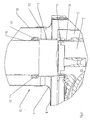
Fig. 2 eine Schnittdarstellung der Anschlußeinrichtung im betriebsbereiten Zustand und -
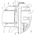
Fig. 3 eine Schnittdarstellung der Anschlußeinrichtung mit getrennter Abgasleitung. - Gleiche Bezugszeichen bedeuten in allen Figuren gleiche Einzelteile.
- In einer Unterdruckkammer 6 ist ein Gebläse 2 an einem Abgassammler 3 angeordnet. Dabei ist an dem Auslaßstutzen 14 über einen Schiebestutzen 1 ein Abgasrohr einer kombinierten Abgas-Luftleitung 15 angeschlossen.
- Der Schiebestutzen 1 ist mit einer unverlierbaren Klemmschraube 4 am Anschlußstutzen 14 fixierbar.
- Die Unterdruckkammer 6, die mit einem Deckel 8 versehen ist, ist mit einem Anschlußstutzen 7 versehen, an dem das äußere Luft führende Rohr 10 der Abgas-Luftleitung 15 mit einer Schelle 11 befestigt ist.
- Wie aus der
Fig. 2 zu ersehen ist, ist zur Verbindung eines inneren Abgas führenden Rohres 9 der kombinierten Abgas-Luftleitung 15 der Schiebestutzen 1 vorgesehen, der mit einer Schiebedichtung 12, die in einer umlaufenden Sicke 13 des Schiebestutzens 1 gehalten ist, die in einem Endbereich des Schiebestutzens 1 angeordnet ist. - An der Stirnseite des zweiten Endes des Schiebestutzens 1 ist eine umlaufende Nut 5 angeordnet, in die in der betriebsbereiten Stellung, die in der
Fig. 2 dargestellt ist, der Auslaßstutzen 14 des Gebläses 2 eingreift und eine Art Labyrinthdichtung bildet. - Dieser Schiebestutzen 1 kann im Bedarfsfall, wie in der
Fig. 3 dargestellt, entlang des Abgasrohres 9 hochgeschoben werden. Dies ermöglicht einen sehr einfachen Zugang zum Gebläse 2 und zum Abgassammler 3 und es wird dadurch ein Ausbau desselben erleichtert. - Um den Schiebestutzen 1 hochschieben zu können, genügt es, den Deckel 8 der Unterdruckkammer 6 zu öffnen, wodurch ein ausreichender Zugang zum Schiebestutzen 1 gegeben ist und die Schraube 4 zu lösen.
Claims (1)
- Anschlußeinrichtung für ein kombiniertes Luft- Abgasrohr (15) an eine Unterdruckkammer (6), bzw. ein Abgasgebläse (2), insbesondere eines Heizgerätes, bei welcher Anschlußeinrichtung das äußere, Luft führende Rohr (10) mit einer Schelle (11) an einem Anschlußstutzen (7) der Unterdruckkammer (6) angeschlossen ist, dadurch gekennzeichnet, dass das Abgasrohr (9) über einen mit einer Gleitdichtung (12) versehenen Schiebestutzen (1) mit einem Auslaßstutzen (14) des Gebläses (2) verbunden ist und der Schiebestutzen (1) an seinem einen Ende stirnseitig mit einer umlaufenden Rille (5) versehen ist, mit dem der Auslaßstutzen (14) des Gebläses (2) in Eingriff bringbar ist.
Applications Claiming Priority (2)
| Application Number | Priority Date | Filing Date | Title |
|---|---|---|---|
| AT14252000 | 2000-08-18 | ||
| AT0142500A AT503704B1 (de) | 2000-08-18 | 2000-08-18 | Anschlusseinrichtung |
Publications (3)
| Publication Number | Publication Date |
|---|---|
| EP1180643A2 EP1180643A2 (de) | 2002-02-20 |
| EP1180643A3 EP1180643A3 (de) | 2002-08-21 |
| EP1180643B1 true EP1180643B1 (de) | 2008-04-02 |
Family
ID=3688218
Family Applications (1)
| Application Number | Title | Priority Date | Filing Date |
|---|---|---|---|
| EP01119395A Expired - Lifetime EP1180643B1 (de) | 2000-08-18 | 2001-08-11 | Anschlusseinrichtung für ein kombiniertes Luft-Abgasrohr |
Country Status (4)
| Country | Link |
|---|---|
| EP (1) | EP1180643B1 (de) |
| AT (2) | AT503704B1 (de) |
| DE (2) | DE50113808D1 (de) |
| ES (1) | ES2303515T3 (de) |
Family Cites Families (7)
| Publication number | Priority date | Publication date | Assignee | Title |
|---|---|---|---|---|
| DE8604045U1 (de) * | 1986-02-12 | 1986-04-10 | Joh. Vaillant Gmbh U. Co, 5630 Remscheid | Verschließbare Sichtöffnung |
| DE3632890A1 (de) * | 1986-09-27 | 1988-04-07 | Bruno Lampka | Anschlussstutzen zum einbau in schamottewaende |
| DE3704130C2 (de) * | 1987-02-11 | 1995-06-22 | Bosch Gmbh Robert | Gasbeheizter Wassererhitzer mit einer geschlossenen Verbrennungskammer |
| DE3878344D1 (de) * | 1987-08-18 | 1993-03-25 | Vaillant Joh Gmbh & Co | Stossverbindung fuer aus zwei konzentrischen rohren bestehende rohrschuesse. |
| AT392530B (de) * | 1988-06-14 | 1991-04-25 | Rapido Waermetechnik Gmbh | Anschluss eines abgasfuehrungsrohres |
| AT399929B (de) * | 1992-10-02 | 1995-08-25 | Vaillant Gmbh | Verbindungseinrichtung |
| DE29810921U1 (de) * | 1998-06-18 | 1999-11-04 | Robert Bosch Gmbh, 70469 Stuttgart | Abgasanschluß für gasbeheizte Wandgeräte, insbesondere Wassererhitzer |
-
2000
- 2000-08-18 AT AT0142500A patent/AT503704B1/de not_active IP Right Cessation
-
2001
- 2001-08-11 EP EP01119395A patent/EP1180643B1/de not_active Expired - Lifetime
- 2001-08-11 AT AT01119395T patent/ATE391268T1/de active
- 2001-08-11 ES ES01119395T patent/ES2303515T3/es not_active Expired - Lifetime
- 2001-08-11 DE DE50113808T patent/DE50113808D1/de not_active Expired - Lifetime
- 2001-08-13 DE DE10139325A patent/DE10139325A1/de not_active Withdrawn
Also Published As
| Publication number | Publication date |
|---|---|
| AT503704B1 (de) | 2008-06-15 |
| ATE391268T1 (de) | 2008-04-15 |
| ES2303515T3 (es) | 2008-08-16 |
| EP1180643A3 (de) | 2002-08-21 |
| DE10139325A1 (de) | 2002-04-25 |
| EP1180643A2 (de) | 2002-02-20 |
| AT503704A1 (de) | 2007-12-15 |
| DE50113808D1 (de) | 2008-05-15 |
Similar Documents
| Publication | Publication Date | Title |
|---|---|---|
| EP0153991B1 (de) | Zuführungsstück für die Atemgase bei der Hochfrequenzbeatmung | |
| DE4425863A1 (de) | Saug- und Blasvorrichtung | |
| DE3529543C2 (de) | ||
| DE19717799C2 (de) | Baueinheit für eine Kompaktheizungsanlage | |
| EP0415049B1 (de) | Düsenanordnung für einen Gasbrenner | |
| AT503704B1 (de) | Anschlusseinrichtung | |
| AT411387B (de) | Heizeinrichtung | |
| EP0913634B1 (de) | Gasbrenner | |
| EP0445413B1 (de) | Brenner mit Abgasrückführung, insbesondere Gebläsebrenner | |
| DE4241622A1 (de) | Rohrkupplung | |
| EP0263333A2 (de) | Drall-Luftauslass | |
| DE10048499A1 (de) | Abgasrückführeinrichtung | |
| DE4441617C1 (de) | Filteranordnung | |
| AT400981B (de) | Luftleitung für ein mit einem brenner versehenes heizgerät | |
| DE2802112C3 (de) | Anordnung eines Auspuffrohres an Kraftfahrzeugen, insbesondere an landwirtschaftlich oder bauwirtschaftlich nutzbaren Motorfahrzeugen | |
| DE102013012021A1 (de) | Anschlussvorrichtung | |
| EP3798530B1 (de) | Gehäuse zum abführen von kondensat eines heizgeräts sowie heizgerät mit einem solchen gehäuse | |
| AT523245B1 (de) | Heizgerät, insbesondere Gasbrennwertgerät | |
| DE29810921U1 (de) | Abgasanschluß für gasbeheizte Wandgeräte, insbesondere Wassererhitzer | |
| DE10002943A1 (de) | Heizeinrichtung | |
| DE202005004954U1 (de) | Geflanschte Abgas- und Luftführungssysteme | |
| EP0445393A2 (de) | Brenner mit Abgasrückführung, insbesondere Gebläsebrenner | |
| DE8806847U1 (de) | Vorrichtung zum Anschluß eines brennstoffbeheizten Gerätes an einem Kamin | |
| DE3105074C2 (de) | Ansaugvorrichtung für Flüssigkeitsförderpumpen | |
| DE202016101125U1 (de) | Rohreinheit zur Luftversorgung sowie Abführung von Abgasen von Verbrennungseinrichtungen |
Legal Events
| Date | Code | Title | Description |
|---|---|---|---|
| PUAI | Public reference made under article 153(3) epc to a published international application that has entered the european phase |
Free format text: ORIGINAL CODE: 0009012 |
|
| AK | Designated contracting states |
Kind code of ref document: A2 Designated state(s): AT BE CH CY DE DK ES FI FR GB GR IE IT LI LU MC NL PT SE TR |
|
| AX | Request for extension of the european patent |
Free format text: AL;LT;LV;MK;RO;SI |
|
| PUAL | Search report despatched |
Free format text: ORIGINAL CODE: 0009013 |
|
| AK | Designated contracting states |
Kind code of ref document: A3 Designated state(s): AT BE CH CY DE DK ES FI FR GB GR IE IT LI LU MC NL PT SE TR |
|
| AX | Request for extension of the european patent |
Free format text: AL;LT;LV;MK;RO;SI |
|
| 17P | Request for examination filed |
Effective date: 20030116 |
|
| 17Q | First examination report despatched |
Effective date: 20030326 |
|
| AKX | Designation fees paid |
Designated state(s): AT BE CH CY DE DK ES FI FR GB GR IE IT LI LU MC NL PT SE TR |
|
| GRAP | Despatch of communication of intention to grant a patent |
Free format text: ORIGINAL CODE: EPIDOSNIGR1 |
|
| GRAS | Grant fee paid |
Free format text: ORIGINAL CODE: EPIDOSNIGR3 |
|
| GRAA | (expected) grant |
Free format text: ORIGINAL CODE: 0009210 |
|
| AK | Designated contracting states |
Kind code of ref document: B1 Designated state(s): AT BE CH CY DE DK ES FI FR GB GR IE IT LI LU MC NL PT SE TR |
|
| REG | Reference to a national code |
Ref country code: GB Ref legal event code: FG4D Free format text: NOT ENGLISH |
|
| REG | Reference to a national code |
Ref country code: CH Ref legal event code: EP Ref country code: IE Ref legal event code: FG4D Free format text: LANGUAGE OF EP DOCUMENT: GERMAN |
|
| REF | Corresponds to: |
Ref document number: 50113808 Country of ref document: DE Date of ref document: 20080515 Kind code of ref document: P |
|
| REG | Reference to a national code |
Ref country code: ES Ref legal event code: FG2A Ref document number: 2303515 Country of ref document: ES Kind code of ref document: T3 |
|
| NLV1 | Nl: lapsed or annulled due to failure to fulfill the requirements of art. 29p and 29m of the patents act | ||
| REG | Reference to a national code |
Ref country code: IE Ref legal event code: FD4D |
|
| PG25 | Lapsed in a contracting state [announced via postgrant information from national office to epo] |
Ref country code: PT Free format text: LAPSE BECAUSE OF FAILURE TO SUBMIT A TRANSLATION OF THE DESCRIPTION OR TO PAY THE FEE WITHIN THE PRESCRIBED TIME-LIMIT Effective date: 20080902 Ref country code: FI Free format text: LAPSE BECAUSE OF FAILURE TO SUBMIT A TRANSLATION OF THE DESCRIPTION OR TO PAY THE FEE WITHIN THE PRESCRIBED TIME-LIMIT Effective date: 20080402 Ref country code: NL Free format text: LAPSE BECAUSE OF FAILURE TO SUBMIT A TRANSLATION OF THE DESCRIPTION OR TO PAY THE FEE WITHIN THE PRESCRIBED TIME-LIMIT Effective date: 20080402 |
|
| PGFP | Annual fee paid to national office [announced via postgrant information from national office to epo] |
Ref country code: FR Payment date: 20080606 Year of fee payment: 8 |
|
| EN | Fr: translation not filed | ||
| PG25 | Lapsed in a contracting state [announced via postgrant information from national office to epo] |
Ref country code: DK Free format text: LAPSE BECAUSE OF FAILURE TO SUBMIT A TRANSLATION OF THE DESCRIPTION OR TO PAY THE FEE WITHIN THE PRESCRIBED TIME-LIMIT Effective date: 20080402 Ref country code: SE Free format text: LAPSE BECAUSE OF FAILURE TO SUBMIT A TRANSLATION OF THE DESCRIPTION OR TO PAY THE FEE WITHIN THE PRESCRIBED TIME-LIMIT Effective date: 20080702 Ref country code: IE Free format text: LAPSE BECAUSE OF FAILURE TO SUBMIT A TRANSLATION OF THE DESCRIPTION OR TO PAY THE FEE WITHIN THE PRESCRIBED TIME-LIMIT Effective date: 20080402 |
|
| PLBE | No opposition filed within time limit |
Free format text: ORIGINAL CODE: 0009261 |
|
| STAA | Information on the status of an ep patent application or granted ep patent |
Free format text: STATUS: NO OPPOSITION FILED WITHIN TIME LIMIT |
|
| 26N | No opposition filed |
Effective date: 20090106 |
|
| PG25 | Lapsed in a contracting state [announced via postgrant information from national office to epo] |
Ref country code: MC Free format text: LAPSE BECAUSE OF NON-PAYMENT OF DUE FEES Effective date: 20080831 |
|
| GBPC | Gb: european patent ceased through non-payment of renewal fee |
Effective date: 20080811 |
|
| PG25 | Lapsed in a contracting state [announced via postgrant information from national office to epo] |
Ref country code: BE Free format text: LAPSE BECAUSE OF NON-PAYMENT OF DUE FEES Effective date: 20080831 |
|
| PG25 | Lapsed in a contracting state [announced via postgrant information from national office to epo] |
Ref country code: CY Free format text: LAPSE BECAUSE OF FAILURE TO SUBMIT A TRANSLATION OF THE DESCRIPTION OR TO PAY THE FEE WITHIN THE PRESCRIBED TIME-LIMIT Effective date: 20080402 |
|
| PG25 | Lapsed in a contracting state [announced via postgrant information from national office to epo] |
Ref country code: GB Free format text: LAPSE BECAUSE OF NON-PAYMENT OF DUE FEES Effective date: 20080811 |
|
| PG25 | Lapsed in a contracting state [announced via postgrant information from national office to epo] |
Ref country code: LU Free format text: LAPSE BECAUSE OF NON-PAYMENT OF DUE FEES Effective date: 20080811 |
|
| PG25 | Lapsed in a contracting state [announced via postgrant information from national office to epo] |
Ref country code: TR Free format text: LAPSE BECAUSE OF FAILURE TO SUBMIT A TRANSLATION OF THE DESCRIPTION OR TO PAY THE FEE WITHIN THE PRESCRIBED TIME-LIMIT Effective date: 20080402 |
|
| PG25 | Lapsed in a contracting state [announced via postgrant information from national office to epo] |
Ref country code: GR Free format text: LAPSE BECAUSE OF FAILURE TO SUBMIT A TRANSLATION OF THE DESCRIPTION OR TO PAY THE FEE WITHIN THE PRESCRIBED TIME-LIMIT Effective date: 20080703 |
|
| PG25 | Lapsed in a contracting state [announced via postgrant information from national office to epo] |
Ref country code: FR Free format text: LAPSE BECAUSE OF FAILURE TO SUBMIT A TRANSLATION OF THE DESCRIPTION OR TO PAY THE FEE WITHIN THE PRESCRIBED TIME-LIMIT Effective date: 20090123 |
|
| PGFP | Annual fee paid to national office [announced via postgrant information from national office to epo] |
Ref country code: DE Payment date: 20150803 Year of fee payment: 15 Ref country code: ES Payment date: 20150701 Year of fee payment: 15 Ref country code: CH Payment date: 20150805 Year of fee payment: 15 |
|
| PGFP | Annual fee paid to national office [announced via postgrant information from national office to epo] |
Ref country code: AT Payment date: 20150803 Year of fee payment: 15 |
|
| PGFP | Annual fee paid to national office [announced via postgrant information from national office to epo] |
Ref country code: IT Payment date: 20150831 Year of fee payment: 15 |
|
| REG | Reference to a national code |
Ref country code: DE Ref legal event code: R119 Ref document number: 50113808 Country of ref document: DE |
|
| REG | Reference to a national code |
Ref country code: CH Ref legal event code: PL |
|
| REG | Reference to a national code |
Ref country code: AT Ref legal event code: MM01 Ref document number: 391268 Country of ref document: AT Kind code of ref document: T Effective date: 20160811 |
|
| PG25 | Lapsed in a contracting state [announced via postgrant information from national office to epo] |
Ref country code: LI Free format text: LAPSE BECAUSE OF NON-PAYMENT OF DUE FEES Effective date: 20160831 Ref country code: CH Free format text: LAPSE BECAUSE OF NON-PAYMENT OF DUE FEES Effective date: 20160831 |
|
| PG25 | Lapsed in a contracting state [announced via postgrant information from national office to epo] |
Ref country code: AT Free format text: LAPSE BECAUSE OF NON-PAYMENT OF DUE FEES Effective date: 20160811 |
|
| PG25 | Lapsed in a contracting state [announced via postgrant information from national office to epo] |
Ref country code: DE Free format text: LAPSE BECAUSE OF NON-PAYMENT OF DUE FEES Effective date: 20170301 |
|
| PG25 | Lapsed in a contracting state [announced via postgrant information from national office to epo] |
Ref country code: IT Free format text: LAPSE BECAUSE OF NON-PAYMENT OF DUE FEES Effective date: 20160811 |
|
| PG25 | Lapsed in a contracting state [announced via postgrant information from national office to epo] |
Ref country code: ES Free format text: LAPSE BECAUSE OF NON-PAYMENT OF DUE FEES Effective date: 20160812 |
|
| REG | Reference to a national code |
Ref country code: ES Ref legal event code: FD2A Effective date: 20180625 |