EP1175534B1 - Wassersparende toilettenanlage - Google Patents
Wassersparende toilettenanlage Download PDFInfo
- Publication number
- EP1175534B1 EP1175534B1 EP00908897A EP00908897A EP1175534B1 EP 1175534 B1 EP1175534 B1 EP 1175534B1 EP 00908897 A EP00908897 A EP 00908897A EP 00908897 A EP00908897 A EP 00908897A EP 1175534 B1 EP1175534 B1 EP 1175534B1
- Authority
- EP
- European Patent Office
- Prior art keywords
- outlet pipe
- section
- accordance
- fact
- pipe
- Prior art date
- Legal status (The legal status is an assumption and is not a legal conclusion. Google has not performed a legal analysis and makes no representation as to the accuracy of the status listed.)
- Expired - Lifetime
Links
- XLYOFNOQVPJJNP-UHFFFAOYSA-N water Substances O XLYOFNOQVPJJNP-UHFFFAOYSA-N 0.000 claims abstract description 33
- 238000011010 flushing procedure Methods 0.000 claims abstract description 16
- 230000015572 biosynthetic process Effects 0.000 claims description 3
- 238000000071 blow moulding Methods 0.000 claims description 3
- 239000002699 waste material Substances 0.000 claims 4
- 229920002994 synthetic fiber Polymers 0.000 claims 2
- 230000008602 contraction Effects 0.000 claims 1
- 238000000465 moulding Methods 0.000 claims 1
- 239000007788 liquid Substances 0.000 abstract description 2
- 238000000034 method Methods 0.000 description 8
- 230000000694 effects Effects 0.000 description 6
- 238000009434 installation Methods 0.000 description 6
- 238000004140 cleaning Methods 0.000 description 3
- 210000003608 fece Anatomy 0.000 description 2
- 239000012528 membrane Substances 0.000 description 2
- 238000010521 absorption reaction Methods 0.000 description 1
- 239000000919 ceramic Substances 0.000 description 1
- 230000001419 dependent effect Effects 0.000 description 1
- 238000002474 experimental method Methods 0.000 description 1
- 238000004519 manufacturing process Methods 0.000 description 1
- 239000000463 material Substances 0.000 description 1
- 239000002184 metal Substances 0.000 description 1
- 238000010926 purge Methods 0.000 description 1
- 239000008237 rinsing water Substances 0.000 description 1
- 230000000630 rising effect Effects 0.000 description 1
Images


Classifications
-
- E—FIXED CONSTRUCTIONS
- E03—WATER SUPPLY; SEWERAGE
- E03D—WATER-CLOSETS OR URINALS WITH FLUSHING DEVICES; FLUSHING VALVES THEREFOR
- E03D11/00—Other component parts of water-closets, e.g. noise-reducing means in the flushing system, flushing pipes mounted in the bowl, seals for the bowl outlet, devices preventing overflow of the bowl contents; devices forming a water seal in the bowl after flushing, devices eliminating obstructions in the bowl outlet or preventing backflow of water and excrements from the waterpipe
- E03D11/18—Siphons
Definitions
- the invention relates to a drain sheet for a water-saving toilet installation according to Preamble of claim 1.
- US-A-2,055,490 discloses a drainage arch with the mer- malenals of the preamble of claim 1, which is after a narrowed and vertical area below in a horizontally extending L-shaped outflow ends. So in the sequence sheet a closed Flow can be formed, however, is comparatively a lot of rinse water required.
- a water-saving flushing device for a toilet is through DE 298 07 813 U1 proposed.
- To a toilet with comparatively to be able to rinse a small amount of rinse water effectively is Bottom of the odor trap a nozzle arranged through which during a rinse, a portion of the rinse water at an angle into the outlet is injected.
- the nozzle is located at a front End of a discharge slope, leaving a negative pressure in the drain is generated when a curved discharge pipe is filled. Through the nozzle should a downward pulling force of the watercourse be strengthened.
- Vacuum toilets have the disadvantage that a vacuum source is installed must be, which is relatively expensive and additional Claimed space. In addition, there are noises in the vacuum actuation hard to avoid. For toilet facilities with a Nozzle in the odor trap are corresponding lines to this Nozzle required. This nozzle makes the production of the toilet bowl more expensive considerably. In addition, the nozzle can clog, resulting in Disruptions leads.
- FR-A-1,148,893 discloses a toilet installation with a drain, which is bent several times.
- the invention is based on the object of a water-saving To create toilet facility, which has the above-mentioned disadvantages avoids and still effective and reliable and cost-effective can be produced.
- the water-saving toilet system is neither a vacuum source another nozzle in the odor trap required.
- the Essential features of the invention relate to the process. This is essentially a flow sheet be formed, the said vertical Area with the comparatively small free cross-section owns and essentially to every common toilet bowl can be grown. A significant advantage The invention is thus seen in that such a flow sheet attached to existing toilet bowls and thus very cost-effective a reduction of water consumption possible is.
- the drain bend can be made of plastic as a fitting and allows very different installation situations. In particular, a floor drain or a wall connection possible. When draining the floor leads the drain line through the building floor and the wall connection through the building wall. Experiments have shown that efficient rinsing with about 4.5 liters of rinse water or even less possible is. According to a development of the invention, the Drain underneath said vertical area a deflection arc on, which has a free cross-section, the larger is as the free cross section of said vertical Range.
- the invention thus relates to a drain sheet for a water-saving toilet facility.
- This is preferably a Shaped for connection to a nozzle of a toilet bowl runs horizontally at the upper end. At this end The drain bend can be attached to the neck of the bowl become.
- At the lower end of the discharge bend is preferably also provided a horizontally extending area. in the horizontal area is a deflection arc in which Forms a flush after a so-called swamp. Of the free cross section of the deflection arc is greater than the free one Cross section of the vertical area.
- the drain bend is connected to the disposal line. This can, as mentioned, vertically through the building floor or pass horizontally through a building wall.
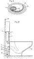
- the toilet unit 1 contains a toilet with a bowl 8, for example, made of ceramic or plastic is. Attached is the bowl 8, for example a support frame 6, which has two trusses 6b, where attached to the bowl 8, for example, is screwed.
- the frame 6 has at the bottom of feet 6 a, which on a Building floor 7 are and are attached to this.
- the support frame 6 is at a distance to a Building wall 33 arranged.
- a discharge bend 14 In the space between the building wall 33 and the support frame 6 is a discharge bend 14, at its lower end 19 via an intermediate piece 20 is connected to a disposal line 21.
- a wall connection not shown here, in which a correspondingly shaped intermediate piece 20, the lower end 19 with a disposal line in the building wall 33 connects.
- cistern 2 is provided to the Rinse operation has at least one key 3 and after the rinsing process via a supply line 4 again filled becomes.
- the cistern 2 can also by a pressure line or another flushing device to be replaced.
- a rinsing process includes basically the cleaning of the bowl 8, the removal the feces and refilling an odor trap 10. On the individual steps of the flushing process is detailed below.
- a cylindrical neck 12 integrally formed, which has a free cross-section A and seen in the flow direction after the odor trap. 8 is arranged.
- a preferably circular opening 12a of the Stutzens 12 leads into the flow sheet 14, with an upper, substantially horizontally extending end 15 to the Nozzle 12 is connected.
- a rubber-elastic gasket 13 seals the nozzle 12 against the drain bend 14 off.
- the end 15 leads via a bend 16 in a vertical region 17, which has a free cross-section C. and, as can be seen, arranged behind the support frame 6 is.
- the vertical area 17 is essential longer than wide and leads to a lower end Deflection arc 18, which after a rising portion 18 a on a horizontal outflow end 19 is connected.
- the deflector 18 is preferably formed by a bend 25, which at the vertical portion 17 and the outlet end 19 is formed.
- the drain sheet 14 thus forms with the deflection arc 18 and the expiry end 19 a unit.
- the flow sheet 14 is preferably made of plastic, in principle is however also another material, for example metal, conceivable.
- the drain end 19 has a circular opening 19a, through which the sheet 14 is connected to the intermediate piece 20 is.
- the free cross section C is much smaller than the free cross-section A of the neck 12.
- the free cross-section E of the discharge end 19 is smaller than the cross section D of the deflection arc 18.
- the free cross-section D is again larger as the cross section C.
- the ratio of the cross section C to Cross-section A is preferably less than 0.7.
- the free one Cross-section D is, as mentioned, larger than the free cross-section C. He is preferably larger by the measure, which is formed by the height d of the backwater 22 ( Figure 2b).
- the cross-section E of the discharge end 19 is preferably about same as the free section C of the vertical section 17.
- the stowage height H shown in Figure 3, which by the Overflow edge 28 is defined, is much larger than the diameter of the vertical pipe section 14.
- the water level H is 4 to 7 times bigger than the inner one Diameter of vertical area 14.
- the inside diameter of the flow sheet 14 in the vertical region 17 is, for example 50 mm.
- the inner diameter according to the cross section B for example 100 mm.
- the diameter in the region of the cross section A is for example, about 70 to 80 mm. Seen in the flow direction the free cross section after the nozzle 12 is thus essential close. In the region of the deflection 18 then takes place again an extension and then again a narrowing.
- FIG. 3 shows schematically the system 1 in the idle state.
- the odor trap 10 is filled with water 11.
- the level 24 of the water 11 is determined by the overflow edge 28.
- the water 11 seals the interior 34 of the bowl 8 from the drain sheet 14 from.
- FIG. 4 shows the beginning of a rinsing process in which through the nozzles 9a in the direction of the arrows 23 water in the Interior 34 flows.
- the level 24 rises accordingly and in flow sheet 14 forms a flow 27.
- By steering the flow through the Swamp the flow is distributed in the cross section E, that an air inlet at the cross section E is prevented.
- the Drain sheet 14 is formed comparatively quickly a closed Flow 27 ', as Figure 5 shows.
- the level 24 Now rises approximately to the top 30 of the deflection arc 37, as Figure 5 clearly shows.
- the rinsing effect can be further increased if according to Figure 9, the inlet nozzles 9a with respect to the bowl edge 8a run diagonally. This forms during refilling and Cleaning the bowl, a rinse roll 32 shown in Figure 9, which extends from the edge 8a to the drain opening 31 and the faster filling of the bowl 8 and a stronger rinsing and thus a more intensive cleaning of the Bowl 8 causes.
- the vortex 32 thus supports the above explained effect of the flow sheet 14.
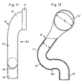
- FIGS. 10 to 12 show a drainage bend 14 ', which is a upper and substantially horizontally extending end 15 ', a region 17 ', a deflecting bend 18' and an outlet end 19 '.
- This drain sheet 14 ' is preferably for a near-wall and vertical ground connection provided, such as this is shown in FIG.
- This drain sheet 14 ' needed little space between a building wall 35 and the Back 36 of a toilet bowl 8. It is essential in this Drainage 14 'that is essential for a backwater Deflection arc 18 'with the vertical portion 17' in a plane which is substantially perpendicular to the longitudinal axis of the nozzle 12 runs. In this plane preferably also runs the drain end 19 ', which extends vertically down here.
- the area at the outlet bend 14 vertically extending 17 is an oblique region in this variant 17 '.
- the diameter C 'of this area 17' is also essential smaller than the diameter B 'of the connection bend 16 '. Since the drainage arch 14 'takes up little space in the depth, the toilet bowl 8 can be especially close to the building wall 35 are mounted, which is especially true for small spaces a significant advantage. It is also advantageous that the Drain sheet 14 'can be made in one piece and a Intermediate piece 20 is not required. The drain sheet 14 ' thus allows a particularly simple installation.
- the drainage bend 14 "shown in FIGS. 13 to 16 is preferably a blow molding of plastic and is at an upper edge 41 on the rear wall 8 a of the bowl eighth attached. At a lower, vertical end 19 " is the flow sheet 14 '' by means of a rubber seal 40 at the disposal line 21 connected.
- the deflecting bend 43 forms a receiving space 45 for the flowing through the nozzle 12 in the flow sheet 14 "flowing Water.
- a constriction 44 which the free inner cross-section B "on the smaller inner cross section C " The constriction 44 and the lower end 19 "is the discharge bend 14 '' S-shaped in a parallel to the back 8a Plane bent.
- An upper arch S 1 of this S-shaped area has a plurality of inwardly directed ribs 46 to 51 and forms an angle ⁇ , which is preferably greater than 90 °.
- An upper rib 46 forms the upper end of the sheet S 1 and a lower rib 51 forms the lower end of the sheet S 1 .
- Between the two completely circumferential ribs 46 to 51 are further completely circumferential ribs 47 and 49 and only partially circumferential ribs 48 and 50.
- Another rib 52 is disposed directly at the upper end of the discharge end 19 ''.
- the exact course of the S-shaped region as well as the arrangement of the ribs 46 to 52 can be seen in FIGS. 13 to 15. The operation of the sequence sheet 14 "will be explained below.
- ribs 46 to 52 are the flow of rinse water break and thus the formation of a closed flow support. It is also advantageous that such ribs 46 to 52 in the blow molding relatively easy to produce are. As explained the curves of the drain bend 14 "in a plane parallel to the rear side 8a, the space requirement is comparatively small. After all Also the assembly of the drain bend 14 "is very easy.
Landscapes
- Health & Medical Sciences (AREA)
- Life Sciences & Earth Sciences (AREA)
- Engineering & Computer Science (AREA)
- Hydrology & Water Resources (AREA)
- Public Health (AREA)
- Water Supply & Treatment (AREA)
- Sanitary Device For Flush Toilet (AREA)
- Sink And Installation For Waste Water (AREA)
- Bidet-Like Cleaning Device And Other Flush Toilet Accessories (AREA)
Description
Ein Ausführungsbeispiel der Erfindung wird nachfolgend anhand der Zeichnungen näher erläutert. Dabei zeigen die Figuren 1-12 nicht alle wesentliche Merhmale der Erfindung. Es zeigen:
- Figur 1
- schematisch einen vertikalen Schnitt durch eine Toilettenanlage,
- Figur 2a
- schematisch eine Ansicht der Rückseite der Toilettenanlage gemäss Figur 1,
- Figur 2b
- einen Schnitt durch den unteren Teil eines Ablaufbogens,
- Figuren 3 bis 9
- schematisch einzelne Schritte des Spülvorgangs,
- Figur 10
- schematisch im Teilschnitt eine Toilettenanlage mit einem Ablaufbogen,
- Figur 11
- eine Ansicht des Ablaufbogens gemäss Figur 10,
- Figur 12
- eine weitere, teilweise geschnittene Ansicht des Bogens gemäss Figur 11,
- Figur 13
- schematisch eine Ansicht der Rückseite einer Toilettenanlage gemäss einem Ausführungsbeispiel
- Figur 14
- eine Draufsicht auf die Anlage gemäss Figur 13,
- Figur 15
- ein Teilschnitt durch den Ablaufbogen der Anlage gemäss Figur 14 und
- Figur 16
- ein Schnitt durch das obere Ende des Ablaufbogens gemäss Figur 15.
Claims (21)
- Ablaufbogen für eine wassersparende Toilettenanlage, mit einem einen Geruchsverschluss (10) aufweisenden Becken (8) und einer Spülvorrichtung (2), mit welcher das Becken (8) spülbar ist , wobei der Ablaufbogen (14) in Strömungsrichtung gesehen nach dem Geruchsverschluss (10) an eine Entsorgungsleitung (21) anzuschliessen ist und durch den beim Spülen Spülwasser und mittransportierte Teile der Entsorgungsleitung (21) zuführbar sind, welcher Ablaufbogen (14) einen im Wesentlichen vertikalen Bereich (17) aufweist, der einen kleineren freien Querschnitt (C) besitzt als ein über diesem Bereich angeordneter weiterer Bereich (A) des Ablaufbogens (14), derart, dass bei einer Spülung dem genannten vertikalen Bereich (17) mehr Wasser zufliesst als von diesem weg und sich eine geschlossene Wasserströmung (27') bildet, welche den Geruchsverschluss (10) im Wesentlichen leer saugt, dadurch gekennzeichnet, dass der Ablaufbogen (14) nach dem im wesentlichen vertikalen Bereich (17) in S-förmiger Anordnung einen oberen und einen unteren Bogen (S1, S2) und , zur Bildung von weiteren Verengungen, nach innen vorspringende Rippen (46-52) aufweist.
- Ablaufbogen nach Anspruch 1, dadurch gekennzeichnet, dass der Ablaufbogen (14) unterhalb des genannten vertikalen Bereichs (17) einen freien Querschnitt (D) besitzt, der grösser ist als der freie Querschnitt (C) des genannten vertikalen Bereichs (17).
- Ablaufbogen nach Anspruch 1 oder 2, dadurch gekennzeichnet, dass das Verhältnis des freien Querschnitts (C) des vertikalen Bereichs (17) zum freien hydraulischen Querschnitt (A) eines Ablaufstutzens (12) im wesentlichen gleich oder kleiner ist als 0,8.
- Ablaufbogen nach Anspruch 2 oder 3, dadurch gekennzeichnet, dass der Ablaufbogen (14) so ausgebildet ist, dass sich nach einer Spülung in diesem ein sogenannter Sumpf (22) bildet und der freie Querschnitt (D) des Ablaufbogens nach diesem Sumpf (22) grösser ist als der freie Querschnitt (C) des genannten vertikalen Bereichs.
- Ablaufbogen nach einem der Ansprüche 2 bis 4, dadurch gekennzeichnet, dass am unteren Ende des Ablaufbogens (14) ein Ablaufende (19) angeordnet ist, das einen freien Querschnitt (E) aufweist, der im wesentlichen dem freien Querschnitt (C) des genannten vertikalen Bereichs (17) entspricht.
- Ablaufbogen nach einem der Ansprüche 1 bis 5, dadurch gekennzeichnet, dass der Ablaufbogen (14) eine die Stauhöhe (H) bildet, die um ein Mehrfaches grösser ist als der Durchmesser im vertikalen Bereich (17).
- Ablaufbogen nach Anspruch 6, dadurch gekennzeichnet, dass das Verhältnis im Bereich 4:1 bis 7:1 liegt.
- Ablaufbogen nach einem der Ansprüche 1 bis 7, dadurch gekennzeichnet, dass der Ablaufbogen (14) ein Kunststoffrohrteil ist.
- Toilettenanlage mit einem einen Geruchsverschluss (10) aufweisenden Becken (8) und einer Spülvorrichtung (2), mit welcher das Becken (8) Spülbar ist, und mit einem Ablaufbogen (14) gemäss Anspruch 1, wobei der Ablaufbogen (14) in Strömungsrichtung nach dem Geruchsverschluss (10) an eine Entsorgungsleitung (21) anzuschliessen ist und durch den beim Spülen Spülwasser und mit transportierte Teile der Entsorgungsleitung (21) zuführban sind, und wobei der Ablaufbogen separat hergestellt und auf den Ablaufstutzen (12) der Toilettenschüssel (8) aufsetzbar ist.
- Ablaufbogen nach Anspruch 7, dadurch gekennzeichnet, dass er ein Formstück ist.
- Toilettenanlage nach Anspruch 9 Ablaufbogen nach Anspruch 10, dadurch gekennzeichnet, dass der Ablaufbogen an seinem unteren Ende einen Sumpf (22) bildet und die Strömung so lenkt, dass sie sich im Querschnitt (E) so verteilt, dass ein Lufteintritt verhindert wird.
- Ablaufbogen nach einem der Ansprüche 8, 10 und 11 oder Toilettenanlage nach Anspruch 9, dadurch gekennzeichnet, dass die beiden Bogen (S1,S2) in einer Ebene verlaufen, die sich quer zur Längsrichtung des Stutzens (12) der Klosettschüssel (8) erstreckt.
- Ablaufbogen nach Anspruch 12, dadurch gekennzeichnet, dass er ein lotrecht verlaufendes Ablaufende (19') aufweist.
- Ablaufbogen nach Anspruch 12 oder 13, dadurch gekennzeichnet, dass der obere Bogen (S1) und ein Anschlussbogen (16') mit einem schräg verlaufenden Rohrbereich (17') verbunden sind.
- Toilettenanlage nach Anspruch 9, dadurch gekennzeichnet, dass der freie Querschnitt (B",C") unterhalb eines Umlenkbogens (43) verjüngt ist.
- Ablaufbogen nach Anspruch 1, dadurch gekennzeichnet, dass am unteren Bogen (S2) ein lotrecht verlaufendes Ablaufende (19') angeformt ist, das vertikal nach unten offen ist.
- Ablaufbogen nach Anspruch 16, dadurch gekennzeichnet, dass die beiden Bogen (S1,S2) unterschiedliche Öffnungswinkel (a,β) aufweisen.
- Ablaufbogen nach Anspruch 17, dadurch gekennzeichnet, dass der obere Bogen (S1) einen Öffnungswinkel (a) aufweist, der grösser als 90° ist.
- Ablaufbogen nach Anspruch 17 oder 18, dadurch gekennzeichnet, dass der untere Bogen (S2) einen Öffnungswinkel (β) aufweist, der kleiner als 90° ist.
- Ablaufbogen nach Anspruch 19, dadurch gekennzeichnet, dass die Rippen (46-52) im Bereich der beiden Bogen (S1,S2) angeordnet sind.
- Toilettenanlage nach Anspruch 9 oder Ablaufbogen nach einem der Ansprüche 10 bis 20, dadurch ge-kennzeichnet, dass der Ablaufbogen ein Blasformteil aus Kunststoff ist.
Applications Claiming Priority (5)
| Application Number | Priority Date | Filing Date | Title |
|---|---|---|---|
| CH82799 | 1999-05-04 | ||
| CH82799 | 1999-05-04 | ||
| CH137899 | 1999-07-27 | ||
| CH137899 | 1999-07-27 | ||
| PCT/CH2000/000160 WO2000066841A1 (de) | 1999-05-04 | 2000-03-20 | Wassersparende toilettenanlage |
Publications (2)
| Publication Number | Publication Date |
|---|---|
| EP1175534A1 EP1175534A1 (de) | 2002-01-30 |
| EP1175534B1 true EP1175534B1 (de) | 2005-04-27 |
Family
ID=25685820
Family Applications (1)
| Application Number | Title | Priority Date | Filing Date |
|---|---|---|---|
| EP00908897A Expired - Lifetime EP1175534B1 (de) | 1999-05-04 | 2000-03-20 | Wassersparende toilettenanlage |
Country Status (7)
| Country | Link |
|---|---|
| EP (1) | EP1175534B1 (de) |
| AT (1) | ATE294287T1 (de) |
| AU (1) | AU3141300A (de) |
| CA (1) | CA2370152A1 (de) |
| DE (1) | DE50010169D1 (de) |
| MX (1) | MXPA01010465A (de) |
| WO (1) | WO2000066841A1 (de) |
Cited By (1)
| Publication number | Priority date | Publication date | Assignee | Title |
|---|---|---|---|---|
| EP4183945A1 (de) * | 2021-11-23 | 2023-05-24 | Roger Vidale | Sanitäranschluss für hängetoilette |
Families Citing this family (2)
| Publication number | Priority date | Publication date | Assignee | Title |
|---|---|---|---|---|
| DE10314640A1 (de) * | 2003-04-01 | 2004-10-14 | Keramag Keramische Werke Ag | WC und zugehöriges Installationselement |
| US8321967B2 (en) * | 2008-08-01 | 2012-12-04 | Kohler Co. | Wall installed toilet |
Family Cites Families (7)
| Publication number | Priority date | Publication date | Assignee | Title |
|---|---|---|---|---|
| US380854A (en) | 1888-04-10 | boyle | ||
| US2055490A (en) * | 1935-02-02 | 1936-09-29 | Pierce John B Foundation | Evacuator |
| US2055489A (en) * | 1935-04-04 | 1936-09-29 | Pierce John B Foundation | Adjustable evacuator |
| FR1148893A (fr) * | 1955-03-18 | 1957-12-17 | Branche de siphon et son application aux water-closets | |
| JPS6475741A (en) * | 1987-09-16 | 1989-03-22 | Toto Ltd | Water closet |
| US5487193A (en) | 1992-04-17 | 1996-01-30 | Fluidmaster, Inc. | Enhanced operation toilet |
| DE29807813U1 (de) | 1998-04-30 | 1998-07-30 | Top Valve Co., Ltd., Taipeh/T'ai-pei | Wassersparende Spüleinrichtung für Toilette |
-
2000
- 2000-03-20 EP EP00908897A patent/EP1175534B1/de not_active Expired - Lifetime
- 2000-03-20 MX MXPA01010465A patent/MXPA01010465A/es unknown
- 2000-03-20 WO PCT/CH2000/000160 patent/WO2000066841A1/de not_active Ceased
- 2000-03-20 AT AT00908897T patent/ATE294287T1/de not_active IP Right Cessation
- 2000-03-20 DE DE50010169T patent/DE50010169D1/de not_active Expired - Fee Related
- 2000-03-20 AU AU31413/00A patent/AU3141300A/en not_active Abandoned
- 2000-03-20 CA CA002370152A patent/CA2370152A1/en not_active Abandoned
Cited By (2)
| Publication number | Priority date | Publication date | Assignee | Title |
|---|---|---|---|---|
| EP4183945A1 (de) * | 2021-11-23 | 2023-05-24 | Roger Vidale | Sanitäranschluss für hängetoilette |
| FR3129418A1 (fr) * | 2021-11-23 | 2023-05-26 | Roger VIDALE | Raccord de plomberie pour toilettes suspendues |
Also Published As
| Publication number | Publication date |
|---|---|
| CA2370152A1 (en) | 2000-11-09 |
| ATE294287T1 (de) | 2005-05-15 |
| DE50010169D1 (de) | 2005-06-02 |
| WO2000066841A1 (de) | 2000-11-09 |
| EP1175534A1 (de) | 2002-01-30 |
| AU3141300A (en) | 2000-11-17 |
| MXPA01010465A (es) | 2002-05-06 |
Similar Documents
| Publication | Publication Date | Title |
|---|---|---|
| EP1247910B1 (de) | Geruchsverschluss für ein wasserloses Urinal | |
| DE9416495U1 (de) | Dachwassereinlauf | |
| AT5032U1 (de) | Absaugesiphon für eine spüleinrichtung | |
| DE69023285T2 (de) | Toilettenschüssel. | |
| EP1175534B1 (de) | Wassersparende toilettenanlage | |
| EP3825480A1 (de) | Spülwasserverteiler | |
| EP1120500B1 (de) | Toilettenschüssel | |
| DE202021106357U1 (de) | Toilette mit Wasserspülung | |
| EP0185109B1 (de) | Geruchsverschluss | |
| DE102023123249A1 (de) | Anordnungssystem zur Anordnung eines Spülbehälters eines Sanitärausstattungsgegenstandes | |
| EP1600676A1 (de) | Tauwasserablaufventil | |
| EP1832689A1 (de) | Unterdruckabwassereinrichtung | |
| DE102013102379A1 (de) | Ablaufanordnung | |
| DE102005036464B3 (de) | Geruchsverschluss | |
| DE10204683B4 (de) | Becken | |
| EP0916775B1 (de) | Kastenkörper für einen Spülkasten | |
| EP3825479A1 (de) | Spülwasserverteiler | |
| EP1416098B1 (de) | Absaugesiphon für eine Abflussinstallation | |
| CH716366B1 (de) | Spülwasserverteiler für einen Sanitärartikel. | |
| EP3421676B1 (de) | Geruchsverschlusselement zum einbau in einen abfluss, insbesondere in den abfluss eines wasserlosen urinals | |
| DE29807813U1 (de) | Wassersparende Spüleinrichtung für Toilette | |
| WO2001053618A2 (de) | Sanitärsystem | |
| EP0757135A1 (de) | Spülkasten | |
| EP1138839B1 (de) | Zweiteiliges Urinal | |
| DE102023123248A1 (de) | Anordnungssystem zur Anordnung eines Spülbehälters eines Sanitärausstattungsgegenstandes |
Legal Events
| Date | Code | Title | Description |
|---|---|---|---|
| PUAI | Public reference made under article 153(3) epc to a published international application that has entered the european phase |
Free format text: ORIGINAL CODE: 0009012 |
|
| 17P | Request for examination filed |
Effective date: 20011025 |
|
| AK | Designated contracting states |
Kind code of ref document: A1 Designated state(s): AT BE CH CY DE DK ES FI FR GB GR IE IT LI LU MC NL PT SE |
|
| AX | Request for extension of the european patent |
Free format text: AL PAYMENT 20011025;LT PAYMENT 20011025;LV PAYMENT 20011025;MK PAYMENT 20011025;RO PAYMENT 20011025;SI PAYMENT 20011025 |
|
| 17Q | First examination report despatched |
Effective date: 20040224 |
|
| GRAP | Despatch of communication of intention to grant a patent |
Free format text: ORIGINAL CODE: EPIDOSNIGR1 |
|
| GRAS | Grant fee paid |
Free format text: ORIGINAL CODE: EPIDOSNIGR3 |
|
| GRAA | (expected) grant |
Free format text: ORIGINAL CODE: 0009210 |
|
| AK | Designated contracting states |
Kind code of ref document: B1 Designated state(s): AT BE CH CY DE DK ES FI FR GB GR IE IT LI LU MC NL PT SE |
|
| AX | Request for extension of the european patent |
Extension state: AL LT LV MK RO SI |
|
| PG25 | Lapsed in a contracting state [announced via postgrant information from national office to epo] |
Ref country code: IE Free format text: LAPSE BECAUSE OF FAILURE TO SUBMIT A TRANSLATION OF THE DESCRIPTION OR TO PAY THE FEE WITHIN THE PRESCRIBED TIME-LIMIT Effective date: 20050427 Ref country code: FI Free format text: LAPSE BECAUSE OF FAILURE TO SUBMIT A TRANSLATION OF THE DESCRIPTION OR TO PAY THE FEE WITHIN THE PRESCRIBED TIME-LIMIT Effective date: 20050427 |
|
| REG | Reference to a national code |
Ref country code: GB Ref legal event code: FG4D Free format text: NOT ENGLISH |
|
| REG | Reference to a national code |
Ref country code: CH Ref legal event code: NV Representative=s name: ISLER & PEDRAZZINI AG Ref country code: CH Ref legal event code: EP |
|
| REG | Reference to a national code |
Ref country code: IE Ref legal event code: FG4D Free format text: LANGUAGE OF EP DOCUMENT: GERMAN |
|
| REF | Corresponds to: |
Ref document number: 50010169 Country of ref document: DE Date of ref document: 20050602 Kind code of ref document: P |
|
| GBT | Gb: translation of ep patent filed (gb section 77(6)(a)/1977) |
Effective date: 20050518 |
|
| PG25 | Lapsed in a contracting state [announced via postgrant information from national office to epo] |
Ref country code: SE Free format text: LAPSE BECAUSE OF FAILURE TO SUBMIT A TRANSLATION OF THE DESCRIPTION OR TO PAY THE FEE WITHIN THE PRESCRIBED TIME-LIMIT Effective date: 20050727 Ref country code: GR Free format text: LAPSE BECAUSE OF FAILURE TO SUBMIT A TRANSLATION OF THE DESCRIPTION OR TO PAY THE FEE WITHIN THE PRESCRIBED TIME-LIMIT Effective date: 20050727 Ref country code: DK Free format text: LAPSE BECAUSE OF FAILURE TO SUBMIT A TRANSLATION OF THE DESCRIPTION OR TO PAY THE FEE WITHIN THE PRESCRIBED TIME-LIMIT Effective date: 20050727 |
|
| PG25 | Lapsed in a contracting state [announced via postgrant information from national office to epo] |
Ref country code: PT Free format text: LAPSE BECAUSE OF FAILURE TO SUBMIT A TRANSLATION OF THE DESCRIPTION OR TO PAY THE FEE WITHIN THE PRESCRIBED TIME-LIMIT Effective date: 20051010 |
|
| LTIE | Lt: invalidation of european patent or patent extension |
Effective date: 20050427 |
|
| REG | Reference to a national code |
Ref country code: IE Ref legal event code: FD4D |
|
| PGFP | Annual fee paid to national office [announced via postgrant information from national office to epo] |
Ref country code: CH Payment date: 20060117 Year of fee payment: 7 |
|
| PGFP | Annual fee paid to national office [announced via postgrant information from national office to epo] |
Ref country code: AT Payment date: 20060207 Year of fee payment: 7 |
|
| PGFP | Annual fee paid to national office [announced via postgrant information from national office to epo] |
Ref country code: FR Payment date: 20060209 Year of fee payment: 7 |
|
| PGFP | Annual fee paid to national office [announced via postgrant information from national office to epo] |
Ref country code: GB Payment date: 20060213 Year of fee payment: 7 |
|
| PGFP | Annual fee paid to national office [announced via postgrant information from national office to epo] |
Ref country code: NL Payment date: 20060215 Year of fee payment: 7 |
|
| PGFP | Annual fee paid to national office [announced via postgrant information from national office to epo] |
Ref country code: DE Payment date: 20060217 Year of fee payment: 7 |
|
| PGFP | Annual fee paid to national office [announced via postgrant information from national office to epo] |
Ref country code: BE Payment date: 20060303 Year of fee payment: 7 |
|
| PLBE | No opposition filed within time limit |
Free format text: ORIGINAL CODE: 0009261 |
|
| STAA | Information on the status of an ep patent application or granted ep patent |
Free format text: STATUS: NO OPPOSITION FILED WITHIN TIME LIMIT |
|
| ET | Fr: translation filed | ||
| PG25 | Lapsed in a contracting state [announced via postgrant information from national office to epo] |
Ref country code: LU Free format text: LAPSE BECAUSE OF NON-PAYMENT OF DUE FEES Effective date: 20060331 Ref country code: MC Free format text: LAPSE BECAUSE OF NON-PAYMENT OF DUE FEES Effective date: 20060331 |
|
| PGFP | Annual fee paid to national office [announced via postgrant information from national office to epo] |
Ref country code: IT Payment date: 20060331 Year of fee payment: 7 |
|
| 26N | No opposition filed |
Effective date: 20060130 |
|
| REG | Reference to a national code |
Ref country code: CH Ref legal event code: PCAR Free format text: ISLER & PEDRAZZINI AG;POSTFACH 1772;8027 ZUERICH (CH) |
|
| REG | Reference to a national code |
Ref country code: CH Ref legal event code: PL |
|
| PG25 | Lapsed in a contracting state [announced via postgrant information from national office to epo] |
Ref country code: AT Free format text: LAPSE BECAUSE OF NON-PAYMENT OF DUE FEES Effective date: 20070320 |
|
| GBPC | Gb: european patent ceased through non-payment of renewal fee |
Effective date: 20070320 |
|
| NLV4 | Nl: lapsed or anulled due to non-payment of the annual fee |
Effective date: 20071001 |
|
| BERE | Be: lapsed |
Owner name: *GEBERIT TECHNIK A.G. Effective date: 20070331 |
|
| PG25 | Lapsed in a contracting state [announced via postgrant information from national office to epo] |
Ref country code: BE Free format text: LAPSE BECAUSE OF NON-PAYMENT OF DUE FEES Effective date: 20070331 |
|
| REG | Reference to a national code |
Ref country code: FR Ref legal event code: ST Effective date: 20071130 |
|
| PG25 | Lapsed in a contracting state [announced via postgrant information from national office to epo] |
Ref country code: NL Free format text: LAPSE BECAUSE OF NON-PAYMENT OF DUE FEES Effective date: 20071001 Ref country code: DE Free format text: LAPSE BECAUSE OF NON-PAYMENT OF DUE FEES Effective date: 20071002 |
|
| PG25 | Lapsed in a contracting state [announced via postgrant information from national office to epo] |
Ref country code: LI Free format text: LAPSE BECAUSE OF NON-PAYMENT OF DUE FEES Effective date: 20070331 Ref country code: CH Free format text: LAPSE BECAUSE OF NON-PAYMENT OF DUE FEES Effective date: 20070331 |
|
| PG25 | Lapsed in a contracting state [announced via postgrant information from national office to epo] |
Ref country code: GB Free format text: LAPSE BECAUSE OF NON-PAYMENT OF DUE FEES Effective date: 20070320 |
|
| PG25 | Lapsed in a contracting state [announced via postgrant information from national office to epo] |
Ref country code: FR Free format text: LAPSE BECAUSE OF NON-PAYMENT OF DUE FEES Effective date: 20070402 |
|
| PG25 | Lapsed in a contracting state [announced via postgrant information from national office to epo] |
Ref country code: CY Free format text: LAPSE BECAUSE OF FAILURE TO SUBMIT A TRANSLATION OF THE DESCRIPTION OR TO PAY THE FEE WITHIN THE PRESCRIBED TIME-LIMIT Effective date: 20050427 |
|
| PG25 | Lapsed in a contracting state [announced via postgrant information from national office to epo] |
Ref country code: ES Free format text: LAPSE BECAUSE OF NON-PAYMENT OF DUE FEES Effective date: 20060331 |
|
| PG25 | Lapsed in a contracting state [announced via postgrant information from national office to epo] |
Ref country code: IT Free format text: LAPSE BECAUSE OF NON-PAYMENT OF DUE FEES Effective date: 20070320 |