EP4183945A1 - Sanitäranschluss für hängetoilette - Google Patents
Sanitäranschluss für hängetoilette Download PDFInfo
- Publication number
- EP4183945A1 EP4183945A1 EP22209012.8A EP22209012A EP4183945A1 EP 4183945 A1 EP4183945 A1 EP 4183945A1 EP 22209012 A EP22209012 A EP 22209012A EP 4183945 A1 EP4183945 A1 EP 4183945A1
- Authority
- EP
- European Patent Office
- Prior art keywords
- sleeves
- sheath
- plumbing
- wall
- plumbing fitting
- Prior art date
- Legal status (The legal status is an assumption and is not a legal conclusion. Google has not performed a legal analysis and makes no representation as to the accuracy of the status listed.)
- Pending
Links
- 238000009428 plumbing Methods 0.000 title claims abstract description 24
- 239000000463 material Substances 0.000 claims abstract description 25
- XLYOFNOQVPJJNP-UHFFFAOYSA-N water Substances O XLYOFNOQVPJJNP-UHFFFAOYSA-N 0.000 claims abstract description 19
- 229920002457 flexible plastic Polymers 0.000 claims abstract description 6
- 239000002351 wastewater Substances 0.000 claims abstract description 6
- 238000009434 installation Methods 0.000 claims description 15
- 229920003023 plastic Polymers 0.000 claims description 15
- 239000004033 plastic Substances 0.000 claims description 15
- 230000006835 compression Effects 0.000 claims description 11
- 238000007906 compression Methods 0.000 claims description 11
- 238000004519 manufacturing process Methods 0.000 claims description 10
- 238000011010 flushing procedure Methods 0.000 claims description 6
- -1 polyethylene Polymers 0.000 claims description 6
- 238000002347 injection Methods 0.000 claims description 4
- 239000007924 injection Substances 0.000 claims description 4
- 238000003780 insertion Methods 0.000 claims description 4
- 230000037431 insertion Effects 0.000 claims description 4
- 238000003466 welding Methods 0.000 claims description 4
- 239000004698 Polyethylene Substances 0.000 claims description 3
- 239000004743 Polypropylene Substances 0.000 claims description 3
- 239000003292 glue Substances 0.000 claims description 3
- 229920000573 polyethylene Polymers 0.000 claims description 3
- 229920001155 polypropylene Polymers 0.000 claims description 3
- 229920002635 polyurethane Polymers 0.000 claims description 3
- 239000004814 polyurethane Substances 0.000 claims description 3
- 239000004800 polyvinyl chloride Substances 0.000 claims description 3
- 229920000915 polyvinyl chloride Polymers 0.000 claims description 3
- 238000000034 method Methods 0.000 description 5
- 238000000465 moulding Methods 0.000 description 5
- 230000008878 coupling Effects 0.000 description 3
- 238000010168 coupling process Methods 0.000 description 3
- 238000005859 coupling reaction Methods 0.000 description 3
- VYPSYNLAJGMNEJ-UHFFFAOYSA-N Silicium dioxide Chemical compound O=[Si]=O VYPSYNLAJGMNEJ-UHFFFAOYSA-N 0.000 description 2
- 238000004026 adhesive bonding Methods 0.000 description 2
- 239000002184 metal Substances 0.000 description 2
- 229910052751 metal Inorganic materials 0.000 description 2
- 230000003647 oxidation Effects 0.000 description 2
- 238000007254 oxidation reaction Methods 0.000 description 2
- 230000010363 phase shift Effects 0.000 description 2
- 230000003014 reinforcing effect Effects 0.000 description 2
- 239000007787 solid Substances 0.000 description 2
- 210000002700 urine Anatomy 0.000 description 2
- 239000002699 waste material Substances 0.000 description 2
- VYZAMTAEIAYCRO-UHFFFAOYSA-N Chromium Chemical compound [Cr] VYZAMTAEIAYCRO-UHFFFAOYSA-N 0.000 description 1
- 229910000639 Spring steel Inorganic materials 0.000 description 1
- 229910000831 Steel Inorganic materials 0.000 description 1
- 230000001154 acute effect Effects 0.000 description 1
- 230000000712 assembly Effects 0.000 description 1
- 238000000429 assembly Methods 0.000 description 1
- 239000010866 blackwater Substances 0.000 description 1
- 229910052804 chromium Inorganic materials 0.000 description 1
- 239000011651 chromium Substances 0.000 description 1
- 238000010276 construction Methods 0.000 description 1
- 238000009826 distribution Methods 0.000 description 1
- 230000005489 elastic deformation Effects 0.000 description 1
- 235000021183 entrée Nutrition 0.000 description 1
- 238000001125 extrusion Methods 0.000 description 1
- 239000012530 fluid Substances 0.000 description 1
- 238000001746 injection moulding Methods 0.000 description 1
- 230000010354 integration Effects 0.000 description 1
- 239000007788 liquid Substances 0.000 description 1
- 239000012528 membrane Substances 0.000 description 1
- 235000019645 odor Nutrition 0.000 description 1
- 238000002161 passivation Methods 0.000 description 1
- 239000002861 polymer material Substances 0.000 description 1
- 239000000843 powder Substances 0.000 description 1
- 230000002787 reinforcement Effects 0.000 description 1
- 238000009418 renovation Methods 0.000 description 1
- 239000000377 silicon dioxide Substances 0.000 description 1
- 239000000243 solution Substances 0.000 description 1
- 235000014347 soups Nutrition 0.000 description 1
- 238000009003 standardized kity Methods 0.000 description 1
- 239000010959 steel Substances 0.000 description 1
- 239000002436 steel type Substances 0.000 description 1
- 239000000126 substance Substances 0.000 description 1
- 229920001169 thermoplastic Polymers 0.000 description 1
- 239000004416 thermosoftening plastic Substances 0.000 description 1
- 238000004804 winding Methods 0.000 description 1
Images


Classifications
-
- E—FIXED CONSTRUCTIONS
- E03—WATER SUPPLY; SEWERAGE
- E03D—WATER-CLOSETS OR URINALS WITH FLUSHING DEVICES; FLUSHING VALVES THEREFOR
- E03D11/00—Other component parts of water-closets, e.g. noise-reducing means in the flushing system, flushing pipes mounted in the bowl, seals for the bowl outlet, devices preventing overflow of the bowl contents; devices forming a water seal in the bowl after flushing, devices eliminating obstructions in the bowl outlet or preventing backflow of water and excrements from the waterpipe
- E03D11/13—Parts or details of bowls; Special adaptations of pipe joints or couplings for use with bowls, e.g. provisions in bowl construction preventing backflow of waste-water from the bowl in the flushing pipe or cistern, provisions for a secondary flushing, for noise-reducing
- E03D11/14—Means for connecting the bowl to the wall, e.g. to a wall outlet
- E03D11/143—Mounting frames for toilets and urinals
- E03D11/146—Mounting frames for toilets and urinals with incorporated cistern
-
- E—FIXED CONSTRUCTIONS
- E03—WATER SUPPLY; SEWERAGE
- E03D—WATER-CLOSETS OR URINALS WITH FLUSHING DEVICES; FLUSHING VALVES THEREFOR
- E03D11/00—Other component parts of water-closets, e.g. noise-reducing means in the flushing system, flushing pipes mounted in the bowl, seals for the bowl outlet, devices preventing overflow of the bowl contents; devices forming a water seal in the bowl after flushing, devices eliminating obstructions in the bowl outlet or preventing backflow of water and excrements from the waterpipe
- E03D11/13—Parts or details of bowls; Special adaptations of pipe joints or couplings for use with bowls, e.g. provisions in bowl construction preventing backflow of waste-water from the bowl in the flushing pipe or cistern, provisions for a secondary flushing, for noise-reducing
- E03D11/16—Means for connecting the bowl to the floor, e.g. to a floor outlet
-
- F—MECHANICAL ENGINEERING; LIGHTING; HEATING; WEAPONS; BLASTING
- F16—ENGINEERING ELEMENTS AND UNITS; GENERAL MEASURES FOR PRODUCING AND MAINTAINING EFFECTIVE FUNCTIONING OF MACHINES OR INSTALLATIONS; THERMAL INSULATION IN GENERAL
- F16L—PIPES; JOINTS OR FITTINGS FOR PIPES; SUPPORTS FOR PIPES, CABLES OR PROTECTIVE TUBING; MEANS FOR THERMAL INSULATION IN GENERAL
- F16L11/00—Hoses, i.e. flexible pipes
- F16L11/04—Hoses, i.e. flexible pipes made of rubber or flexible plastics
- F16L11/11—Hoses, i.e. flexible pipes made of rubber or flexible plastics with corrugated wall
- F16L11/112—Hoses, i.e. flexible pipes made of rubber or flexible plastics with corrugated wall having reinforcements embedded in the wall
-
- F—MECHANICAL ENGINEERING; LIGHTING; HEATING; WEAPONS; BLASTING
- F16—ENGINEERING ELEMENTS AND UNITS; GENERAL MEASURES FOR PRODUCING AND MAINTAINING EFFECTIVE FUNCTIONING OF MACHINES OR INSTALLATIONS; THERMAL INSULATION IN GENERAL
- F16L—PIPES; JOINTS OR FITTINGS FOR PIPES; SUPPORTS FOR PIPES, CABLES OR PROTECTIVE TUBING; MEANS FOR THERMAL INSULATION IN GENERAL
- F16L27/00—Adjustable joints; Joints allowing movement
- F16L27/10—Adjustable joints; Joints allowing movement comprising a flexible connection only
- F16L27/107—Adjustable joints; Joints allowing movement comprising a flexible connection only the ends of the pipe being interconnected by a flexible sleeve
- F16L27/11—Adjustable joints; Joints allowing movement comprising a flexible connection only the ends of the pipe being interconnected by a flexible sleeve the sleeve having the form of a bellows with multiple corrugations
- F16L27/111—Adjustable joints; Joints allowing movement comprising a flexible connection only the ends of the pipe being interconnected by a flexible sleeve the sleeve having the form of a bellows with multiple corrugations the bellows being reinforced
Definitions
- Suspended toilets require little or no masonry work for their installation, and are therefore often installed in a pre-existing building, for example during renovation work. Drain pipes sometimes lead to a horizontal surface (floor), sometimes to a vertical surface (wall). The outlet angle of the pipe can therefore vary (vertical, horizontal, inclined, etc.). The distance between the water outlet of the seat and the inlet of the evacuation pipe is also variable.
- the document EP 2 900 877 describes in particular a suspended toilet installation comprising such a crenellated flexible pipe.
- the coupling according to the invention has in particular sufficient strength and deformability for its use with suspended toilets. Its deformability allows it in particular to be variable in length, in connection angle and in particular during a non-coplanar configuration of the axes of the outlets of the pipe and of the bowl.
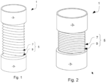
- Sheath 5 of connection 1 of the figure 1 is expanding.
- the turns of the coil spring 7 are spaced apart, and said coil spring 7 is deformed in extension.
- the length of fitting 1 in this state, its maximum extension, is about 25 to 35cm.
- the helical spring 7 By being placed at the top of the folds of the structure, the helical spring 7 also makes it possible to stiffen the helical folds, and therefore the durability of this fold structure, which ensures good flow through the gutters thus formed and high durability in the time.
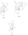
- THE figures 5 to 8 are side views of a connector 1 as previously described, subjected to various deformations in the plane of these figures.
- connection 1 is bent at right angles.
- the axis A1 of the sleeve at the top in figure 7 is at an angle of approximately 45° with respect to the axis A2 of the sleeve 3 at the bottom figure 7 .
- the axes A1, A2 of the sleeves 3 are mutually at right angles.
- fitting 1 is misaligned.
- the axes A1 and A2 of the two sleeves 3 are parallel but not coincident.
- the kit 113 further comprises at least one connector 1, as described above. Further, the kit 113 can include several connectors 1, with different lengths, diameters etc. for greater adaptability.
- the first step 201 is the insertion of a coil spring 7 into a mold 210.
- the mold 210 is shown empty in figure 14 . It comprises two end portions 211, 213, a central bellows portion 215, with spiral folds and thin enough for the molded material to remain flexible, and a spiral housing 217 located at the top of the spiral folds of the central bellows portion. 215.
- the second step 203 is the overmolding of the coil spring 7 by means of a plastic material, injected into the mold 210, in particular at its central bellows portion 215, in the spiral folds. This step generates the flexible and compressible sheath 5.
- the third step 205 is the attachment of the sheath 5 thus obtained to two rigid tubular sleeves 3.
- the injection of the plastic material into the mold 210 is shown in figure 16 .
- the plastic material injected in the fluid state, fills the end portions 211, 213 corresponding to the sleeves 3.
- the end portions 211, 213 are here tubular, with a sufficient thickness for the sleeves 3 obtained to be rigid.
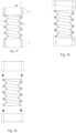
- FIG 18 shows an alternative embodiment of connector 1, obtained by molding in a mold 210 similar to that of figures 14 to 17 .
- the coil spring 7 extends into the sleeves 3, in which it is also molded.
- the step 205 of fixing the sheath 5 to the sleeves 3 then respectively comprises a sub-step of gluing or welding the sheath 5 to the sleeves 3.
Landscapes
- Engineering & Computer Science (AREA)
- General Engineering & Computer Science (AREA)
- Health & Medical Sciences (AREA)
- Life Sciences & Earth Sciences (AREA)
- Hydrology & Water Resources (AREA)
- Public Health (AREA)
- Water Supply & Treatment (AREA)
- Mechanical Engineering (AREA)
- Sanitary Device For Flush Toilet (AREA)
Applications Claiming Priority (1)
| Application Number | Priority Date | Filing Date | Title |
|---|---|---|---|
| FR2112371A FR3129418B1 (fr) | 2021-11-23 | 2021-11-23 | Raccord de plomberie pour toilettes suspendues |
Publications (1)
| Publication Number | Publication Date |
|---|---|
| EP4183945A1 true EP4183945A1 (de) | 2023-05-24 |
Family
ID=79831015
Family Applications (1)
| Application Number | Title | Priority Date | Filing Date |
|---|---|---|---|
| EP22209012.8A Pending EP4183945A1 (de) | 2021-11-23 | 2022-11-23 | Sanitäranschluss für hängetoilette |
Country Status (2)
| Country | Link |
|---|---|
| EP (1) | EP4183945A1 (de) |
| FR (1) | FR3129418B1 (de) |
Citations (4)
| Publication number | Priority date | Publication date | Assignee | Title |
|---|---|---|---|---|
| EP1035260A2 (de) | 1999-03-09 | 2000-09-13 | Geberit Technik Ag | Profilschiene für eine Montagevorrichtung |
| EP1175534A1 (de) | 1999-05-04 | 2002-01-30 | Geberit Technik Ag | Wassersparende toilettenanlage |
| EP2900877A1 (de) | 2012-09-17 | 2015-08-05 | Viega GmbH & Co. KG | Tragvorrichtung für einen sanitärkörper |
| US9371944B2 (en) | 2001-11-24 | 2016-06-21 | Ragner Technology Corporation | Multi-layer pressure actuated extendable hose |
-
2021
- 2021-11-23 FR FR2112371A patent/FR3129418B1/fr active Active
-
2022
- 2022-11-23 EP EP22209012.8A patent/EP4183945A1/de active Pending
Patent Citations (7)
| Publication number | Priority date | Publication date | Assignee | Title |
|---|---|---|---|---|
| EP1035260A2 (de) | 1999-03-09 | 2000-09-13 | Geberit Technik Ag | Profilschiene für eine Montagevorrichtung |
| EP1035260B1 (de) * | 1999-03-09 | 2007-01-31 | Geberit Technik Ag | Profilschiene für eine Montagevorrichtung |
| EP1175534A1 (de) | 1999-05-04 | 2002-01-30 | Geberit Technik Ag | Wassersparende toilettenanlage |
| EP1175534B1 (de) * | 1999-05-04 | 2005-04-27 | Geberit Technik Ag | Wassersparende toilettenanlage |
| US9371944B2 (en) | 2001-11-24 | 2016-06-21 | Ragner Technology Corporation | Multi-layer pressure actuated extendable hose |
| EP2900877A1 (de) | 2012-09-17 | 2015-08-05 | Viega GmbH & Co. KG | Tragvorrichtung für einen sanitärkörper |
| EP2900877B1 (de) * | 2012-09-17 | 2017-11-01 | Viega Technology GmbH & Co. KG | Tragvorrichtung für einen sanitärkörper |
Also Published As
| Publication number | Publication date |
|---|---|
| FR3129418B1 (fr) | 2025-03-21 |
| FR3129418A1 (fr) | 2023-05-26 |
Similar Documents
| Publication | Publication Date | Title |
|---|---|---|
| AU2019203870B2 (en) | Toilet pan body and its method of manufacturing | |
| CN103628546B (zh) | 用于连接导管的挠性法兰装置以及连接所述导管的方法 | |
| EP1328749B1 (de) | Flexible flüssigkeitskupplung | |
| EP1174549A2 (de) | Rückflussverhinderer | |
| EP4183945A1 (de) | Sanitäranschluss für hängetoilette | |
| US20070257218A1 (en) | Backflow-Preventer | |
| EP0310488B1 (de) | Reinigungsöffnung für Anlagen zum Transportieren von Flüssigkeiten | |
| FR2910953A1 (fr) | Pipe de wc extensible | |
| EP1222418B1 (de) | Verbindungsstück | |
| FR2967428A1 (fr) | Element de drainage pour balcon, loggia ou terrasse | |
| FR2719062A3 (fr) | Ensemble modulaire pour avaloirs de caniveaux d'écoulement des eaux. | |
| JP5052276B2 (ja) | 閉塞具およびその取付方法 | |
| JP3756911B2 (ja) | 既設排水桝の点検口蓋装置 | |
| FR2942291A1 (fr) | Coude semi-rigide | |
| US343069A (en) | Andbew eosewatee | |
| FR2674268A1 (fr) | Procede d'obtention d'une colonne d'eau minimale dans un dispositif siphouide et bonde siphouide pour la mise en óoeuvre du procede. | |
| FR3133204A1 (fr) | Siphon de sol a hauteur reglable a isolation accoustique | |
| FR3091917A1 (fr) | Dispositif d’évacuation comprenant une liaison continue élastiquement déformable | |
| FR2649145A1 (fr) | Fond de regard a cunette pour canalisations enterrees, son procede de fabrication et regards comportant un tel fond | |
| FR2764915A1 (fr) | Regard prefabrique pour le raccordement et/ou la visite de canalisations d'assainissement, et procede de mise en place d'un tel regard | |
| FR2544763A1 (fr) | Chambre de captage ou de reunion prefabriquee en beton arme | |
| FR2657371A1 (fr) | Bac ou boitier a empreintes de casse a etancheite amelioree de jonction avec des canalisations et joints d'etancheite adaptes. | |
| BE1012107A6 (fr) | Procede de raccordement d'une cuve. | |
| FR3135292A3 (fr) | Ensemble de tube fourreau | |
| WO2013057454A1 (fr) | Procédé, dispositif et système d'étanchéisation d'un orifice de passage de fluide d'une façade extérieure de bâtiment |
Legal Events
| Date | Code | Title | Description |
|---|---|---|---|
| PUAI | Public reference made under article 153(3) epc to a published international application that has entered the european phase |
Free format text: ORIGINAL CODE: 0009012 |
|
| STAA | Information on the status of an ep patent application or granted ep patent |
Free format text: STATUS: THE APPLICATION HAS BEEN PUBLISHED |
|
| AK | Designated contracting states |
Kind code of ref document: A1 Designated state(s): AL AT BE BG CH CY CZ DE DK EE ES FI FR GB GR HR HU IE IS IT LI LT LU LV MC ME MK MT NL NO PL PT RO RS SE SI SK SM TR |
|
| STAA | Information on the status of an ep patent application or granted ep patent |
Free format text: STATUS: REQUEST FOR EXAMINATION WAS MADE |
|
| 17P | Request for examination filed |
Effective date: 20231115 |
|
| RBV | Designated contracting states (corrected) |
Designated state(s): AL AT BE BG CH CY CZ DE DK EE ES FI FR GB GR HR HU IE IS IT LI LT LU LV MC ME MK MT NL NO PL PT RO RS SE SI SK SM TR |
|
| STAA | Information on the status of an ep patent application or granted ep patent |
Free format text: STATUS: EXAMINATION IS IN PROGRESS |
|
| 17Q | First examination report despatched |
Effective date: 20250219 |