EP1174286A2 - Lagervorrichtung - Google Patents
Lagervorrichtung Download PDFInfo
- Publication number
- EP1174286A2 EP1174286A2 EP01117122A EP01117122A EP1174286A2 EP 1174286 A2 EP1174286 A2 EP 1174286A2 EP 01117122 A EP01117122 A EP 01117122A EP 01117122 A EP01117122 A EP 01117122A EP 1174286 A2 EP1174286 A2 EP 1174286A2
- Authority
- EP
- European Patent Office
- Prior art keywords
- area
- shaft body
- shaft
- face
- bending
- Prior art date
- Legal status (The legal status is an assumption and is not a legal conclusion. Google has not performed a legal analysis and makes no representation as to the accuracy of the status listed.)
- Withdrawn
Links
Images


Classifications
-
- F—MECHANICAL ENGINEERING; LIGHTING; HEATING; WEAPONS; BLASTING
- F16—ENGINEERING ELEMENTS AND UNITS; GENERAL MEASURES FOR PRODUCING AND MAINTAINING EFFECTIVE FUNCTIONING OF MACHINES OR INSTALLATIONS; THERMAL INSULATION IN GENERAL
- F16C—SHAFTS; FLEXIBLE SHAFTS; ELEMENTS OR CRANKSHAFT MECHANISMS; ROTARY BODIES OTHER THAN GEARING ELEMENTS; BEARINGS
- F16C19/00—Bearings with rolling contact, for exclusively rotary movement
- F16C19/02—Bearings with rolling contact, for exclusively rotary movement with bearing balls essentially of the same size in one or more circular rows
- F16C19/14—Bearings with rolling contact, for exclusively rotary movement with bearing balls essentially of the same size in one or more circular rows for both radial and axial load
- F16C19/18—Bearings with rolling contact, for exclusively rotary movement with bearing balls essentially of the same size in one or more circular rows for both radial and axial load with two or more rows of balls
- F16C19/181—Bearings with rolling contact, for exclusively rotary movement with bearing balls essentially of the same size in one or more circular rows for both radial and axial load with two or more rows of balls with angular contact
- F16C19/183—Bearings with rolling contact, for exclusively rotary movement with bearing balls essentially of the same size in one or more circular rows for both radial and axial load with two or more rows of balls with angular contact with two rows at opposite angles
- F16C19/184—Bearings with rolling contact, for exclusively rotary movement with bearing balls essentially of the same size in one or more circular rows for both radial and axial load with two or more rows of balls with angular contact with two rows at opposite angles in O-arrangement
- F16C19/186—Bearings with rolling contact, for exclusively rotary movement with bearing balls essentially of the same size in one or more circular rows for both radial and axial load with two or more rows of balls with angular contact with two rows at opposite angles in O-arrangement with three raceways provided integrally on parts other than race rings, e.g. third generation hubs
-
- B—PERFORMING OPERATIONS; TRANSPORTING
- B60—VEHICLES IN GENERAL
- B60B—VEHICLE WHEELS; CASTORS; AXLES FOR WHEELS OR CASTORS; INCREASING WHEEL ADHESION
- B60B27/00—Hubs
-
- B—PERFORMING OPERATIONS; TRANSPORTING
- B60—VEHICLES IN GENERAL
- B60B—VEHICLE WHEELS; CASTORS; AXLES FOR WHEELS OR CASTORS; INCREASING WHEEL ADHESION
- B60B27/00—Hubs
- B60B27/0005—Hubs with ball bearings
-
- B—PERFORMING OPERATIONS; TRANSPORTING
- B60—VEHICLES IN GENERAL
- B60B—VEHICLE WHEELS; CASTORS; AXLES FOR WHEELS OR CASTORS; INCREASING WHEEL ADHESION
- B60B27/00—Hubs
- B60B27/0015—Hubs for driven wheels
- B60B27/0021—Hubs for driven wheels characterised by torque transmission means from drive axle
- B60B27/0026—Hubs for driven wheels characterised by torque transmission means from drive axle of the radial type, e.g. splined key
-
- B—PERFORMING OPERATIONS; TRANSPORTING
- B60—VEHICLES IN GENERAL
- B60B—VEHICLE WHEELS; CASTORS; AXLES FOR WHEELS OR CASTORS; INCREASING WHEEL ADHESION
- B60B27/00—Hubs
- B60B27/0078—Hubs characterised by the fixation of bearings
- B60B27/0084—Hubs characterised by the fixation of bearings caulking to fix inner race
-
- B—PERFORMING OPERATIONS; TRANSPORTING
- B60—VEHICLES IN GENERAL
- B60B—VEHICLE WHEELS; CASTORS; AXLES FOR WHEELS OR CASTORS; INCREASING WHEEL ADHESION
- B60B27/00—Hubs
- B60B27/0094—Hubs one or more of the bearing races are formed by the hub
-
- F—MECHANICAL ENGINEERING; LIGHTING; HEATING; WEAPONS; BLASTING
- F16—ENGINEERING ELEMENTS AND UNITS; GENERAL MEASURES FOR PRODUCING AND MAINTAINING EFFECTIVE FUNCTIONING OF MACHINES OR INSTALLATIONS; THERMAL INSULATION IN GENERAL
- F16C—SHAFTS; FLEXIBLE SHAFTS; ELEMENTS OR CRANKSHAFT MECHANISMS; ROTARY BODIES OTHER THAN GEARING ELEMENTS; BEARINGS
- F16C43/00—Assembling bearings
- F16C43/04—Assembling rolling-contact bearings
-
- F—MECHANICAL ENGINEERING; LIGHTING; HEATING; WEAPONS; BLASTING
- F16—ENGINEERING ELEMENTS AND UNITS; GENERAL MEASURES FOR PRODUCING AND MAINTAINING EFFECTIVE FUNCTIONING OF MACHINES OR INSTALLATIONS; THERMAL INSULATION IN GENERAL
- F16D—COUPLINGS FOR TRANSMITTING ROTATION; CLUTCHES; BRAKES
- F16D1/00—Couplings for rigidly connecting two coaxial shafts or other movable machine elements
- F16D1/10—Quick-acting couplings in which the parts are connected by simply bringing them together axially
- F16D1/108—Quick-acting couplings in which the parts are connected by simply bringing them together axially having retaining means rotating with the coupling and acting by interengaging parts, i.e. positive coupling
-
- F—MECHANICAL ENGINEERING; LIGHTING; HEATING; WEAPONS; BLASTING
- F16—ENGINEERING ELEMENTS AND UNITS; GENERAL MEASURES FOR PRODUCING AND MAINTAINING EFFECTIVE FUNCTIONING OF MACHINES OR INSTALLATIONS; THERMAL INSULATION IN GENERAL
- F16C—SHAFTS; FLEXIBLE SHAFTS; ELEMENTS OR CRANKSHAFT MECHANISMS; ROTARY BODIES OTHER THAN GEARING ELEMENTS; BEARINGS
- F16C2326/00—Articles relating to transporting
- F16C2326/01—Parts of vehicles in general
- F16C2326/02—Wheel hubs or castors
-
- F—MECHANICAL ENGINEERING; LIGHTING; HEATING; WEAPONS; BLASTING
- F16—ENGINEERING ELEMENTS AND UNITS; GENERAL MEASURES FOR PRODUCING AND MAINTAINING EFFECTIVE FUNCTIONING OF MACHINES OR INSTALLATIONS; THERMAL INSULATION IN GENERAL
- F16C—SHAFTS; FLEXIBLE SHAFTS; ELEMENTS OR CRANKSHAFT MECHANISMS; ROTARY BODIES OTHER THAN GEARING ELEMENTS; BEARINGS
- F16C35/00—Rigid support of bearing units; Housings, e.g. caps, covers
- F16C35/04—Rigid support of bearing units; Housings, e.g. caps, covers in the case of ball or roller bearings
- F16C35/06—Mounting or dismounting of ball or roller bearings; Fixing them onto shaft or in housing
- F16C35/063—Fixing them on the shaft
- F16C35/0635—Fixing them on the shaft the bore of the inner ring being of special non-cylindrical shape which co-operates with a complementary shape on the shaft, e.g. teeth, polygonal sections
-
- F—MECHANICAL ENGINEERING; LIGHTING; HEATING; WEAPONS; BLASTING
- F16—ENGINEERING ELEMENTS AND UNITS; GENERAL MEASURES FOR PRODUCING AND MAINTAINING EFFECTIVE FUNCTIONING OF MACHINES OR INSTALLATIONS; THERMAL INSULATION IN GENERAL
- F16D—COUPLINGS FOR TRANSMITTING ROTATION; CLUTCHES; BRAKES
- F16D1/00—Couplings for rigidly connecting two coaxial shafts or other movable machine elements
- F16D1/10—Quick-acting couplings in which the parts are connected by simply bringing them together axially
- F16D2001/103—Quick-acting couplings in which the parts are connected by simply bringing them together axially the torque is transmitted via splined connections
-
- Y—GENERAL TAGGING OF NEW TECHNOLOGICAL DEVELOPMENTS; GENERAL TAGGING OF CROSS-SECTIONAL TECHNOLOGIES SPANNING OVER SEVERAL SECTIONS OF THE IPC; TECHNICAL SUBJECTS COVERED BY FORMER USPC CROSS-REFERENCE ART COLLECTIONS [XRACs] AND DIGESTS
- Y10—TECHNICAL SUBJECTS COVERED BY FORMER USPC
- Y10T—TECHNICAL SUBJECTS COVERED BY FORMER US CLASSIFICATION
- Y10T29/00—Metal working
- Y10T29/49—Method of mechanical manufacture
- Y10T29/49481—Wheel making
- Y10T29/49492—Land wheel
- Y10T29/49533—Hub making
- Y10T29/49535—Hub making with assembling
-
- Y—GENERAL TAGGING OF NEW TECHNOLOGICAL DEVELOPMENTS; GENERAL TAGGING OF CROSS-SECTIONAL TECHNOLOGIES SPANNING OVER SEVERAL SECTIONS OF THE IPC; TECHNICAL SUBJECTS COVERED BY FORMER USPC CROSS-REFERENCE ART COLLECTIONS [XRACs] AND DIGESTS
- Y10—TECHNICAL SUBJECTS COVERED BY FORMER USPC
- Y10T—TECHNICAL SUBJECTS COVERED BY FORMER US CLASSIFICATION
- Y10T29/00—Metal working
- Y10T29/49—Method of mechanical manufacture
- Y10T29/49481—Wheel making
- Y10T29/49492—Land wheel
- Y10T29/49533—Hub making
- Y10T29/49536—Hub shaping
-
- Y—GENERAL TAGGING OF NEW TECHNOLOGICAL DEVELOPMENTS; GENERAL TAGGING OF CROSS-SECTIONAL TECHNOLOGIES SPANNING OVER SEVERAL SECTIONS OF THE IPC; TECHNICAL SUBJECTS COVERED BY FORMER USPC CROSS-REFERENCE ART COLLECTIONS [XRACs] AND DIGESTS
- Y10—TECHNICAL SUBJECTS COVERED BY FORMER USPC
- Y10T—TECHNICAL SUBJECTS COVERED BY FORMER US CLASSIFICATION
- Y10T29/00—Metal working
- Y10T29/49—Method of mechanical manufacture
- Y10T29/49636—Process for making bearing or component thereof
- Y10T29/49643—Rotary bearing
- Y10T29/49679—Anti-friction bearing or component thereof
- Y10T29/49682—Assembling of race and rolling anti-friction members
-
- Y—GENERAL TAGGING OF NEW TECHNOLOGICAL DEVELOPMENTS; GENERAL TAGGING OF CROSS-SECTIONAL TECHNOLOGIES SPANNING OVER SEVERAL SECTIONS OF THE IPC; TECHNICAL SUBJECTS COVERED BY FORMER USPC CROSS-REFERENCE ART COLLECTIONS [XRACs] AND DIGESTS
- Y10—TECHNICAL SUBJECTS COVERED BY FORMER USPC
- Y10T—TECHNICAL SUBJECTS COVERED BY FORMER US CLASSIFICATION
- Y10T29/00—Metal working
- Y10T29/49—Method of mechanical manufacture
- Y10T29/49636—Process for making bearing or component thereof
- Y10T29/49696—Mounting
Definitions
- the present invention relates to a bearing apparatus such as a vehicle hub unit in which a rolling bearing is mounted to a shaft body.
- a vehicle hub unit will be described.
- a rolling bearing is mounted to an outer periphery of a shaft body of a hub wheel.
- a shaft end of the shaft body is bulged and deformed radially outward by rolling caulking to be a caulked portion.
- This caulked portion is caulked to an outer end face of an inner ring of the bearing to thereby apply a pre-load to the bearing and to prevent coming off of the bearing.
- the shaft body of the hub wheel has a hollow structure such that a drive shaft can be inserted into the shaft body.
- an inner periphery of the shaft body has spline portions.
- the spline portions are formed to be substantially adjacent to the caulked portion of the shaft end and to be formed long in an axial direction so as to mechanically connect the inner periphery of the shaft body and the drive shaft with necessary strength.
- the spline portions are liable to be deformed radially inward to such a degree as to obstruct insertion of the drive shaft into the shaft body by force applied radially outward to the shaft end in caulking for forming the caulked portion.
- the bearing apparatus of the invention includes a hollow shaft body and a rolling bearing mounted to an outer peripheral face of the shaft body; wherein a shaft end of the shaft body is deformed radially outward and caulked to an outer end face of an inner ring provided to the rolling bearing and the shaft body has on an inner peripheral face thereof a first area in which a spline portion in an axial direction is formed, a second area between a bending starting point for bending the shaft end of the shaft body radially outward and an end face of the shaft body, and a third area between the first area and the second area for suppressing deformation of the inner peripheral face of the shaft body caused by the caulking.
- the spline portion is formed to be axially long on the inner periphery of the hollow shaft body so as to be mechanically connected to a spline portion on an outer periphery of a drive shaft, because the third area is provided between the first area and the second area, the first area does not directly receive an influence of radially outward deformation of the shaft end by caulking for forming the caulked portion. As a result, it is possible to maintain high accuracy of the spline portion and the first area is not deformed to such a degree as to obstruct insertion of the drive shaft.
- the third area is preferably set according to the following expression (1): (X1/X2) > (y1/y2) where X1 is an axial distance from a position of a caulking side end portion of the first area to the bending starting point for bending the shaft end of the shaft body radially outward, X2 is an axial distance from the bending starting point to a caulking side outer end face of the inner ring, y1 is a difference between an outside diameter and a pitch diameter of the first area, and y2 is a difference between an outside diameter and an inside diameter of the shaft end of the shaft body.
- FIGs. 1 to 5 A preferred embodiment of the present invention will be described with reference to FIGs. 1 to 5.
- a vehicle hub unit is taken as an example of a bearing apparatus.
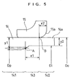
- balls and the like are not shown in FIG. 5 for ease of illustration.
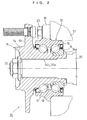
- the hub unit 10 includes a hub wheel 11 and a bearing 12.
- the bearing 12 is a double row angular contact ball bearing with vertex of contact angles outside of bearing as an example of a rolling bearing of a diagonal contact type.
- the hub wheel 11 includes a flange 13 which is in a radially outward orientation and to which a wheel (not shown) is mounted and a hollow shaft 14.
- the bearing 12 includes one inner ring 15 fitted over a small-diameter outer peripheral face of the hollow shaft 14 and having a single race, a single outer ring 16 having two rows of races, a plurality of balls 17 disposed in two rows, and two snap cages 18.
- an inner ring of a general single row angular contact ball bearing is used as it is.
- a large-diameter outer peripheral face of the hollow shaft 14 is used as the other inner ring.
- the flange 19 is provided to an outer periphery of the outer ring 16 in the radially outward orientation.
- a shaft end 14a of the hollow shaft 14 is caulked to a caulking side outer end face of the inner ring 15 from the state in FIG. 1 to the state in FIG. 2. As a result of this caulking, the shaft end 14a becomes a caulked portion.
- the hub unit 10 is mounted between a drive shaft 20 and a shaft case 21 of a vehicle.
- the hollow shaft 14 of the hub wheel 11 is spline-fitted over the drive shaft 20 and connected to the drive shaft 20 through a nut 22.
- the flange 19 of the outer ring 16 of the bearing 12 is connected to the shaft case 21 through a bolt 23 so as not to rotate.
- a reference numeral 14b designates a spline portion formed on an inner periphery of the hollow shaft 14 and a reference numeral 20a designates a spline portion formed on an outer periphery of the drive shaft 20.
- a fitted state of the spline portions 14b of the hollow shaft 14 and the spline portions 20a of the drive shaft 20 is as shown in FIGs. 3 and 4 .
- the respective spline portions 14b and 20a are spaced uniformly in circumferential directions and are in involute shapes.
- shapes of both the spline portions 14b and 20a are not limited to the involute shapes but may be other shapes.
- the spline portions 14b of the hollow shaft 14 are inclined in the circumferential direction. One sides of the spline portions 14b in the circumferential direction are in contact with one sides of the spline portions 20a of the drive shaft 14 in the circumferential direction while the other sides of the spline portions 14b in the circumferential direction are in contact with the other sides of the spline portions 20a in the circumferential direction.
- a spline portion forming area (first area) 141 in which the spline portions 14b are formed and a caulked portion forming area (second area) 142 in which the caulked portion 14a is formed are formed.
- a cushioning area (third area) 143 for suppressing deformation of the inner peripheral face of the hollow shaft 14 caused by caulking of the shaft end 14a of the hollow shaft 14 is provided.
- the first area 141 is an area between axially opposite end faces of the spline portions 14b formed on the inner periphery of the hollow shaft 14 and a caulking side end face on a pitch circle line of the spline portion 14b is defined as a caulking side end portion A of the first area 141.
- the second area 142 is an area from a bending starting point B of the shaft end 14a of the hollow shaft 14 to an end face of the shaft end 14a.
- an inner peripheral edge portion 15a of a caulking side outer end face of the inner ring 15 is chamfered round, e.g., with a quarter of a circumference of a radius of curvature X2 from a center O.
- a point of intersection of a radial line from the center O and the inner peripheral edge portion 15a is defined as the bending starting point B.
- the third area 143 is an area between the caulking side end portion A and the bending starting point B.
- a position of the third area 143 is set according to the following expression (1). (X1/X2) > (y1/y2)
- X2 is the axial distance from the bending starting point B to the caulking side outer end face of the inner ring 15. This is based on setting the axial length X1 of the third area 143 at a large value because the influence of deformation in caulking the shaft end 14a of the hollow shaft 14 on the first area 141 becomes large when the radius of curvature of chamfering of the inner peripheral edge portion 15a of the inner ring 15 becomes large or when a ratio between y2 and y1, i.e., a ratio between wall thicknesses of the first and second areas 141 and 142 becomes large.
- the invention can be similarly applied to a vehicle hub unit having a hollow shaft with a bottom in an axial direction.
- the invention can be similarly applied to a vehicle hub unit for a vehicle follower wheel.
Landscapes
- Engineering & Computer Science (AREA)
- Mechanical Engineering (AREA)
- General Engineering & Computer Science (AREA)
- Rolling Contact Bearings (AREA)
- Support Of The Bearing (AREA)
- Mounting Of Bearings Or Others (AREA)
Priority Applications (1)
| Application Number | Priority Date | Filing Date | Title |
|---|---|---|---|
| EP09016087A EP2168785B1 (de) | 2000-07-17 | 2001-07-13 | Radlager |
Applications Claiming Priority (2)
| Application Number | Priority Date | Filing Date | Title |
|---|---|---|---|
| JP2000215658 | 2000-07-17 | ||
| JP2000215658A JP4299957B2 (ja) | 2000-07-17 | 2000-07-17 | 軸受装置の製造方法 |
Publications (2)
| Publication Number | Publication Date |
|---|---|
| EP1174286A2 true EP1174286A2 (de) | 2002-01-23 |
| EP1174286A3 EP1174286A3 (de) | 2005-06-01 |
Family
ID=18711046
Family Applications (2)
| Application Number | Title | Priority Date | Filing Date |
|---|---|---|---|
| EP09016087A Expired - Lifetime EP2168785B1 (de) | 2000-07-17 | 2001-07-13 | Radlager |
| EP01117122A Withdrawn EP1174286A3 (de) | 2000-07-17 | 2001-07-13 | Lagervorrichtung |
Family Applications Before (1)
| Application Number | Title | Priority Date | Filing Date |
|---|---|---|---|
| EP09016087A Expired - Lifetime EP2168785B1 (de) | 2000-07-17 | 2001-07-13 | Radlager |
Country Status (3)
| Country | Link |
|---|---|
| US (2) | US20020006239A1 (de) |
| EP (2) | EP2168785B1 (de) |
| JP (1) | JP4299957B2 (de) |
Cited By (2)
| Publication number | Priority date | Publication date | Assignee | Title |
|---|---|---|---|---|
| US7069656B2 (en) | 2002-10-12 | 2006-07-04 | Samsung Electronics Co., Ltd. | Methods for manufacturing monolithic ink-jet printheads |
| FR3071887A1 (fr) * | 2017-10-03 | 2019-04-05 | Renault S.A.S. | Portion d'arbre de transmission d'un vehicule automobile, arbre de transmission comprenant une telle portion et dispositif de transmission de couple comprenant un tel arbre de transmission |
Families Citing this family (14)
| Publication number | Priority date | Publication date | Assignee | Title |
|---|---|---|---|---|
| JP4562025B2 (ja) * | 2004-08-16 | 2010-10-13 | Ntn株式会社 | 車輪用軸受装置 |
| JP2006273117A (ja) * | 2005-03-29 | 2006-10-12 | Ntn Corp | 車輪軸受装置 |
| DE102005018127A1 (de) * | 2005-04-20 | 2006-10-26 | Schaeffler Kg | Stirnverzahnung an einem Kupplungselement zum Übertragen von Drehmomenten |
| DE502005008542D1 (de) * | 2005-06-30 | 2009-12-31 | Ford Global Tech Llc | Spielfreie Schraubenverbindung zwischen einer Radnabeneinheit und einem Gelenkwellenstummel (aussen) kurzer Bauweise |
| CN101675259B (zh) * | 2007-04-04 | 2011-12-28 | Ntn株式会社 | 车轮用轴承及具有该车轮用轴承的车轮用轴承装置 |
| JP2007211990A (ja) * | 2007-05-14 | 2007-08-23 | Jtekt Corp | 軸受装置の製造方法 |
| EP2940330B1 (de) * | 2007-09-18 | 2019-02-13 | NTN Corporation | Lagervorrichtung für ein rad |
| CN101852161A (zh) * | 2010-06-07 | 2010-10-06 | 无锡赛可电气有限公司 | 具改进螺旋花键结构的汽车起动机驱动轴 |
| US8616779B2 (en) | 2010-11-29 | 2013-12-31 | Honda Motor Co., Ltd. | Shortened driveshaft stem |
| DE102011057010A1 (de) * | 2011-12-23 | 2013-06-27 | Dr. Ing. H.C. F. Porsche Aktiengesellschaft | Welle-Nabe-Verbindung |
| DE102011057012A1 (de) * | 2011-12-23 | 2013-06-27 | Dr. Ing. H.C. F. Porsche Aktiengesellschaft | Welle-Nabe-Verbindung |
| JP2014043201A (ja) * | 2012-08-28 | 2014-03-13 | Jtekt Corp | 軸受ユニット |
| CA2838652C (en) * | 2013-01-11 | 2018-02-27 | Webb Wheel Products, Inc. | Drum piloting hub |
| JP6449689B2 (ja) * | 2015-03-11 | 2019-01-09 | Ntn株式会社 | 車輪用軸受装置 |
Citations (4)
| Publication number | Priority date | Publication date | Assignee | Title |
|---|---|---|---|---|
| US2015430A (en) * | 1935-03-02 | 1935-09-24 | Int Motor Co | Involute spline shaft |
| US3836272A (en) * | 1973-07-02 | 1974-09-17 | Gen Motors Corp | Connecting device with expanding splines |
| EP0318266A1 (de) * | 1987-11-23 | 1989-05-31 | Eaton Corporation | Presssitz-Keilnutkupplung |
| GB2323823A (en) * | 1997-03-31 | 1998-10-07 | Nsk Ltd | Hub unit for supporting a vehicle wheel |
Family Cites Families (13)
| Publication number | Priority date | Publication date | Assignee | Title |
|---|---|---|---|---|
| FR2666389B1 (fr) * | 1990-09-04 | 1992-10-23 | Roulements Soc Nouvelle | Procede pour realiser une collerette de roulement et ensemble de roulement equipe d'une telle collerette. |
| DE4339847C2 (de) * | 1993-11-23 | 2000-09-14 | Kugelfischer G Schaefer & Co | Lagereinheit |
| DE69831434T2 (de) * | 1997-01-17 | 2006-06-29 | Nsk Ltd. | Lagereinheit für eine Fahrzeugradaufhängung |
| JP3674735B2 (ja) * | 1997-04-23 | 2005-07-20 | 光洋精工株式会社 | ホイール用軸受装置 |
| JP3982093B2 (ja) * | 1998-02-16 | 2007-09-26 | 日本精工株式会社 | 車輪駆動用車軸ユニット |
| JP4016499B2 (ja) * | 1998-09-11 | 2007-12-05 | 株式会社ジェイテクト | ハブユニットの製造方法 |
| DE69932782T2 (de) * | 1998-09-11 | 2007-12-27 | Jtekt Corp., Osaka | Lagervorrichtung |
| JP4123643B2 (ja) * | 1999-06-21 | 2008-07-23 | 株式会社ジェイテクト | 軸力管理方法 |
| DE60131043T2 (de) * | 2000-03-03 | 2008-10-30 | Jtekt Corp. | Lagervorrichtung |
| JP2002089572A (ja) * | 2000-07-10 | 2002-03-27 | Koyo Seiko Co Ltd | 軸受装置 |
| JP2002225503A (ja) * | 2000-11-29 | 2002-08-14 | Nsk Ltd | 車輪支持用ハブユニットの製造方法とその製造用押型 |
| JP4244548B2 (ja) * | 2001-06-20 | 2009-03-25 | 日本精工株式会社 | 駆動輪用転がり軸受ユニットの設計方法 |
| US6772615B2 (en) * | 2001-09-20 | 2004-08-10 | Nsk Ltd. | Method of manufacturing hub unit for supporting wheel and die for manufacturing the same |
-
2000
- 2000-07-17 JP JP2000215658A patent/JP4299957B2/ja not_active Expired - Fee Related
-
2001
- 2001-07-10 US US09/902,230 patent/US20020006239A1/en not_active Abandoned
- 2001-07-13 EP EP09016087A patent/EP2168785B1/de not_active Expired - Lifetime
- 2001-07-13 EP EP01117122A patent/EP1174286A3/de not_active Withdrawn
-
2003
- 2003-10-23 US US10/691,786 patent/US6880247B2/en not_active Expired - Lifetime
Patent Citations (4)
| Publication number | Priority date | Publication date | Assignee | Title |
|---|---|---|---|---|
| US2015430A (en) * | 1935-03-02 | 1935-09-24 | Int Motor Co | Involute spline shaft |
| US3836272A (en) * | 1973-07-02 | 1974-09-17 | Gen Motors Corp | Connecting device with expanding splines |
| EP0318266A1 (de) * | 1987-11-23 | 1989-05-31 | Eaton Corporation | Presssitz-Keilnutkupplung |
| GB2323823A (en) * | 1997-03-31 | 1998-10-07 | Nsk Ltd | Hub unit for supporting a vehicle wheel |
Cited By (2)
| Publication number | Priority date | Publication date | Assignee | Title |
|---|---|---|---|---|
| US7069656B2 (en) | 2002-10-12 | 2006-07-04 | Samsung Electronics Co., Ltd. | Methods for manufacturing monolithic ink-jet printheads |
| FR3071887A1 (fr) * | 2017-10-03 | 2019-04-05 | Renault S.A.S. | Portion d'arbre de transmission d'un vehicule automobile, arbre de transmission comprenant une telle portion et dispositif de transmission de couple comprenant un tel arbre de transmission |
Also Published As
| Publication number | Publication date |
|---|---|
| US6880247B2 (en) | 2005-04-19 |
| EP1174286A3 (de) | 2005-06-01 |
| US20020006239A1 (en) | 2002-01-17 |
| EP2168785A1 (de) | 2010-03-31 |
| JP2002029210A (ja) | 2002-01-29 |
| EP2168785B1 (de) | 2012-01-18 |
| JP4299957B2 (ja) | 2009-07-22 |
| US20040083612A1 (en) | 2004-05-06 |
Similar Documents
| Publication | Publication Date | Title |
|---|---|---|
| EP1174286A2 (de) | Lagervorrichtung | |
| US6672769B2 (en) | Bearing apparatus and producing method thereof | |
| JP2007126087A (ja) | 車輪用軸受装置 | |
| JP2003074571A (ja) | 駆動輪用転がり軸受ユニット及び車輪用駆動ユニット | |
| US20090080825A1 (en) | Angular contact ball bearing | |
| US6832854B2 (en) | Vehicle-use rolling bearing device | |
| KR101414546B1 (ko) | 샤프트를 위한 구름 베어링 | |
| US20130229046A1 (en) | Wheel support device | |
| JP2005233402A (ja) | 転がり軸受装置 | |
| JP5187877B2 (ja) | 車輪用軸受装置 | |
| JP2006153171A (ja) | 転がり軸受装置の製造方法 | |
| US20070204461A1 (en) | Method of manufacturing bearing device for a wheel | |
| JP4239249B2 (ja) | 軸受装置の製造方法 | |
| EP2587078A1 (de) | Radlagervorrichtung | |
| JP2007211990A (ja) | 軸受装置の製造方法 | |
| JP3736571B2 (ja) | 駆動輪用転がり軸受ユニット及び車輪用駆動ユニットの製造方法 | |
| JP4760856B2 (ja) | 車軸用軸受装置 | |
| JP4193353B2 (ja) | 車軸用軸受装置およびその製造方法 | |
| US9162526B2 (en) | Wheel support device | |
| JP2006144990A (ja) | 転がり軸受装置 | |
| JP2004150485A (ja) | 転がり軸受装置 | |
| JP4244114B2 (ja) | 転がり軸受ユニット | |
| JP2001246440A (ja) | 車両用ハブユニットのかしめ方法 | |
| JP2009001273A (ja) | 車両用軸受装置およびその製造方法 | |
| JP2007113719A (ja) | 車輪用軸受装置 |
Legal Events
| Date | Code | Title | Description |
|---|---|---|---|
| PUAI | Public reference made under article 153(3) epc to a published international application that has entered the european phase |
Free format text: ORIGINAL CODE: 0009012 |
|
| AK | Designated contracting states |
Kind code of ref document: A2 Designated state(s): AT BE CH CY DE DK ES FI FR GB GR IE IT LI LU MC NL PT SE TR |
|
| AX | Request for extension of the european patent |
Free format text: AL;LT;LV;MK;RO;SI |
|
| PUAL | Search report despatched |
Free format text: ORIGINAL CODE: 0009013 |
|
| AK | Designated contracting states |
Kind code of ref document: A3 Designated state(s): AT BE CH CY DE DK ES FI FR GB GR IE IT LI LU MC NL PT SE TR |
|
| AX | Request for extension of the european patent |
Extension state: AL LT LV MK RO SI |
|
| 17P | Request for examination filed |
Effective date: 20050809 |
|
| AKX | Designation fees paid |
Designated state(s): DE FR GB IT |
|
| RAP1 | Party data changed (applicant data changed or rights of an application transferred) |
Owner name: JTEKT CORPORATION |
|
| 17Q | First examination report despatched |
Effective date: 20051104 |
|
| 17Q | First examination report despatched |
Effective date: 20051104 |
|
| STAA | Information on the status of an ep patent application or granted ep patent |
Free format text: STATUS: THE APPLICATION IS DEEMED TO BE WITHDRAWN |
|
| 18D | Application deemed to be withdrawn |
Effective date: 20100112 |