EP1167168B1 - Führung für eine Endloskette eines Raupenfahrwerkes - Google Patents
Führung für eine Endloskette eines Raupenfahrwerkes Download PDFInfo
- Publication number
- EP1167168B1 EP1167168B1 EP01250231A EP01250231A EP1167168B1 EP 1167168 B1 EP1167168 B1 EP 1167168B1 EP 01250231 A EP01250231 A EP 01250231A EP 01250231 A EP01250231 A EP 01250231A EP 1167168 B1 EP1167168 B1 EP 1167168B1
- Authority
- EP
- European Patent Office
- Prior art keywords
- guide
- chain
- rails
- webs
- undercarriage
- Prior art date
- Legal status (The legal status is an assumption and is not a legal conclusion. Google has not performed a legal analysis and makes no representation as to the accuracy of the status listed.)
- Expired - Lifetime
Links
- 230000000284 resting effect Effects 0.000 claims 1
- 238000007689 inspection Methods 0.000 description 2
- 238000010276 construction Methods 0.000 description 1
Images


Classifications
-
- B—PERFORMING OPERATIONS; TRANSPORTING
- B62—LAND VEHICLES FOR TRAVELLING OTHERWISE THAN ON RAILS
- B62D—MOTOR VEHICLES; TRAILERS
- B62D55/00—Endless track vehicles
- B62D55/08—Endless track units; Parts thereof
- B62D55/084—Endless-track units or carriages mounted separably, adjustably or extensibly on vehicles, e.g. portable track units
- B62D55/0847—Track blocking devices mounted on the frame; Track guides
Definitions
- the invention relates to a guide for a chain link having several Endless chain of a crawler chassis, especially for cranes according to the generic term of claim 1.
- a generic guide is known from DE 29 05 991 A1.
- the Crawler undercarriage consists of a chassis support, one with chain teeth provided drive turas, a stator, one having several chain links Endless chain, several rollers and a guide for the endless chain.
- each Chain link has two symmetrical to the center of the chain link and at a distance from each other arranged, in the direction of the guide webs on and between the two Guide bars are a lower-lying element connecting the two bars arranged, which meshes with the chain teeth of the drive tura.
- the leadership points a U-shaped support extending over the lower run, on the individual elongated rails are releasably attached to the lower end area via bolts are held in mounting blocks. In the leadership case that comes Inside of the rails on the outside of the guide webs to plant.
- the object of the invention is a guide for a plurality of chain links having endless chain of a crawler track to specify the compact is trained and means less weight.
- the assembly and Dismantling of the rollers is not made difficult by the guide.
- this is directly in front of or behind the drive tura arranged guide designed as a compact pivoting part and in one Frame part of the chassis beam attached. It has two elongated rails Bridges that at least in the working position of the swivel part the upper area of the guide webs of the individual chain links.
- This arrangement has the advantage that it is small and in the space can be easily accommodated between the last roller and the drive tura.
- the lateral forces are absorbed by pedestals, while that in one Recording arranged rubber spring element on a rattling of the pivoting part the endless chain prevented.
- the pivotability has the advantage that when Hinging a chain link up the pivoting part of this movement can yield. Special attention was paid to the recognizability of the Condition of the wear plates.
- the mounting screws are through the Inserted webs and screwed into the wear plates. Are the Wear plates processed, then the end areas of the Grinding screws ground. The mounting screws then have none Stop more and gradually fall through the movement of the crawler track the bore of the webs out. This is immediate with a normal daily inspection recognizable, whereby as a remedy new wear plates with new fastening screws can be assembled.
- Figures 1 and 2 is a partial longitudinal section and in Figure 3 in a cross section a crawler chassis with a guide designed according to the invention once in Working position and once shown in the swiveled position.
- a guide 8 is provided for guiding the endless chain.
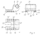
- This consists of a pivoting part 9, the support body 20 (Fig. 4) shoe-like is formed with two parallel web plates 10, 10 '(FIG. 3).
- This Web plates 10, 10 ' are on the right and left on the respective outside 11, 11' of the Guide webs 5.5 'of the respective chain link 3 arranged.
- On the inside 12, 12 'of the web plates 10, 10' are wear plates 13, 13 'by means of screws 14, 14' attached.
- FIGS. 4a-4c show a side view, a front view and a top view the pivot part 9 is shown as a single element. It consists of a shoe-like curved, two-arm support body 20, on the underside of the Are spaced web plates 10, 10 'attached. How nice mentioned can be detachable in the straight section of the web plates 10, 10 ' by means of screws 14, 14 'wear plates 13, 13' are attached. In the right A receptacle 21 is fastened in the upper end region of the two web plates 10, 10 ′ which the rubber spring element 18 can be arranged. Alternatively, it is also possible that Rubber spring element 18 to be attached directly to the pivoting part 9.
Landscapes
- Engineering & Computer Science (AREA)
- Chemical & Material Sciences (AREA)
- Combustion & Propulsion (AREA)
- Transportation (AREA)
- Mechanical Engineering (AREA)
- Devices For Conveying Motion By Means Of Endless Flexible Members (AREA)
- Forklifts And Lifting Vehicles (AREA)
- Chain Conveyers (AREA)
- Machines For Laying And Maintaining Railways (AREA)
Description
- Figur 1
- in einem Teillängsschnitt einen Teilaspekt eines Raupenfahrwerkes mit einer erfindungsgemäß ausgebildeten Führung in Arbeitsstellung.
- Figur 2
- wie Figur 1, aber die Führung in geschwenkter Stellung
- Figur 3
- einen Querschnitt entlang der Linie A-A in Figur 2
- Figur 4a-c
- im Detail das Verschwenkteil
| 1 | Antriebsturas |
| 2 | Kettenzahn |
| 3 | Kettenglied |
| 4 | Bodenplatte |
| 5,5' | Führungssteg |
| 6 | Nockenartiges Element |
| 7 | Laufrolle |
| 8 | Führung |
| 9 | Verschwenkteil |
| 10,10' | Stegblech |
| 11,11' | Außenseite der Führungsstege |
| 12,12' | Innenseite der Stege |
| 13,13' | Verschleißblech |
| 14,14' | Schraube |
| 15,15' | Lagerbock |
| 16,16' | Gestellteil |
| 17 | Achse Verschwenkteil |
| 18 | Gummifederelement |
| 19,19' | Bohrung Steg |
| 20 | Tragkörper |
| 21 | Aufnahme |
Claims (5)
- Führung (8) für eine mehrere Kettenglieder (3) aufweisende Endloskette eines Raupenfahrwerkes, insbesondere für Krane, das einen Fahrwerksträger, mindestens einen mit Kettenzähnen (2) versehenen Antriebsturas (1), ggf. ein Leitrad und mehrere Laufrollen (7) aufweist und jedes Kettenglied der Endloskette zwei symmetrisch zur Mitte des Kettengliedes und im Abstand zueinander angeordnete in Laufrichtung liegende Führungsstege (5, 5') aufweist und zwischen beiden Führungsstegen (5, 5') ein die beiden Stege verbindendes tiefer liegendes Element angeordnet ist, das mit den Kettenzähnen (2) des Antriebsturas (1) kämmt, wobei die Führung (8) zwei parallel zur Laufrichtung der Endloskette liegende Schienen aufweist, deren jeweilige Innenseite im Führungsfall an der Außenseite des jeweiligen Führungssteges (5, 5') zu Anlage kommt,
dadurch gekennzeichnet, dass die unmittelbar vor oder hinter dem Antriebsturas (1) angeordnete Führung (8) als kompaktes Verschwenkteil (9) ausgebildet und in einem Gestellteil (16,16') des Fahrwerksträgers befestigt ist und als Schienen zwei langgestreckte Stegbleche (10,10') aufweist, die bei Arbeitsstellung des Verschwenkteils (9) mindestens in Höhe des oberen Bereichs der Führungsstege (5,5') der einzelnen Kettenglieder (3) liegen. - Führung nach Anspruch 1,
dadurch gekennzeichnet, dass das Verschwenkteil (9) zwischen zwei im Gestellteil (16,16') befestigten Lagerböcken (15,15') gelagert ist. - Führung nach Anspruch 1 und 2,
dadurch gekennzeichnet, dass in der Achse (17) des Verschwenkteiles (9) eine Aufnahme (21) befestigt ist, in der ein Gummifederelement (18) anordenbar ist. - Führung nach einem der Ansprüche 1 bis 3,
dadurch gekennzeichnet, dass auf der Innenseite (12,12') des jeweiligen Stegbleches (10,10') des Verschwenkteiles (9) lösbar Verschleißbleche (13,13') angeordnet sind. - Führung nach Anspruch 4,
dadurch gekennzeichnet, dass die Befestigung der Verschleißbleche (13,13') über durch die Stegbleche (10,10') hindurchsteckbare und in die Verschleißbleche (13,13') einschraubbare Schrauben (14,14') erfolgt.
Applications Claiming Priority (2)
| Application Number | Priority Date | Filing Date | Title |
|---|---|---|---|
| DE10031021 | 2000-06-26 | ||
| DE10031021A DE10031021C1 (de) | 2000-06-26 | 2000-06-26 | Führung für eine Endloskette eines Raupenfahrwerkes |
Publications (3)
| Publication Number | Publication Date |
|---|---|
| EP1167168A2 EP1167168A2 (de) | 2002-01-02 |
| EP1167168A3 EP1167168A3 (de) | 2002-06-26 |
| EP1167168B1 true EP1167168B1 (de) | 2003-11-12 |
Family
ID=7646800
Family Applications (1)
| Application Number | Title | Priority Date | Filing Date |
|---|---|---|---|
| EP01250231A Expired - Lifetime EP1167168B1 (de) | 2000-06-26 | 2001-06-22 | Führung für eine Endloskette eines Raupenfahrwerkes |
Country Status (5)
| Country | Link |
|---|---|
| US (1) | US6520602B2 (de) |
| EP (1) | EP1167168B1 (de) |
| JP (1) | JP2002037149A (de) |
| AT (1) | ATE254060T1 (de) |
| DE (2) | DE10031021C1 (de) |
Families Citing this family (13)
| Publication number | Priority date | Publication date | Assignee | Title |
|---|---|---|---|---|
| US20080284245A1 (en) * | 2007-05-18 | 2008-11-20 | Caterpillar Inc. | Machine track system and machine track segment |
| AT508498B1 (de) * | 2009-07-09 | 2011-09-15 | Sandvik Mining & Constr Oy | Raupenfahrwerk für bergbaumaschinen, sowie kettenglied für ein raupenfahrwerk und verfahren zur herstellung desselben |
| US9352793B2 (en) * | 2013-03-12 | 2016-05-31 | Caterpillar Global Mining Llc | Slide shoe for undercarriage frame assembly |
| AU2014202781B2 (en) | 2013-05-24 | 2017-07-20 | Joy Global Surface Mining Inc | Crawler track |
| CA2871244C (en) * | 2013-11-12 | 2023-05-09 | Harnischfeger Technologies, Inc. | Guide rail for crawler track |
| USD748153S1 (en) | 2014-05-22 | 2016-01-26 | Harnischfeger Technologies, Inc. | Crawler track shoe |
| US10843749B2 (en) | 2018-04-20 | 2020-11-24 | L&H Industrial, Inc. | Straddle mount idler assembly |
| CN110525527B (zh) * | 2019-08-01 | 2024-03-01 | 江苏徐工工程机械研究院有限公司 | 一种三角履带轮及轮齿导向限位装置 |
| FR3101896A1 (fr) * | 2019-10-15 | 2021-04-16 | Watertracks | Robot, système et procédé de curage |
| EP3808906B1 (de) * | 2019-10-15 | 2023-10-04 | Watertracks | Roboter, system und verfahren zum ausbaggern |
| US11834113B2 (en) | 2020-03-06 | 2023-12-05 | L&H Industrial, Inc. | Track slide assembly and crawler shoe system |
| CN116374027B (zh) * | 2023-04-10 | 2025-10-10 | 江苏徐工工程机械研究院有限公司 | 履带式底盘和履带式车辆 |
| US12600420B2 (en) | 2023-07-06 | 2026-04-14 | Caterpillar Inc. | Slider wheel having a plurality of slider surfaces |
Family Cites Families (11)
| Publication number | Priority date | Publication date | Assignee | Title |
|---|---|---|---|---|
| DE315604C (de) * | ||||
| US4082371A (en) * | 1976-08-02 | 1978-04-04 | Deere & Company | Support and guide for a track of a track-laying vehicle |
| US4229053A (en) * | 1978-02-27 | 1980-10-21 | Caterpillar Tractor Co. | Track guide assembly |
| US4583791A (en) * | 1984-03-13 | 1986-04-22 | Kabushiki Kaisha Komatsu Seisakusho | Crawler vehicle undercarriage |
| CA2143383C (en) * | 1994-09-22 | 2000-10-03 | Takao Kouchi | Snow vehicle |
| JPH09188278A (ja) * | 1996-01-12 | 1997-07-22 | Iseki & Co Ltd | 移動農機のクローラ |
| US6074023A (en) * | 1996-07-24 | 2000-06-13 | Hitachi Construction Machinery Co., Ltd. | Guide roller assembly for crawler type vehicles and method for forming guide roller |
| US5738361A (en) * | 1997-05-13 | 1998-04-14 | Landucci; Angelo | Snow bicycle |
| FR2794095B1 (fr) * | 1999-05-28 | 2001-08-31 | Otico | Dispositif d'entrainement a chenille souple pour vehicule tout terrain |
| US6206492B1 (en) * | 1999-07-20 | 2001-03-27 | Caterpillar Inc. | Mid-roller for endless track laying work machine |
| US6267459B1 (en) * | 1999-12-13 | 2001-07-31 | Caterpillar Inc. | Automatic belt alignment system for an endless track laying work machine |
-
2000
- 2000-06-26 DE DE10031021A patent/DE10031021C1/de not_active Expired - Fee Related
-
2001
- 2001-05-25 US US09/866,126 patent/US6520602B2/en not_active Expired - Lifetime
- 2001-06-22 DE DE50100941T patent/DE50100941D1/de not_active Expired - Lifetime
- 2001-06-22 EP EP01250231A patent/EP1167168B1/de not_active Expired - Lifetime
- 2001-06-22 AT AT01250231T patent/ATE254060T1/de not_active IP Right Cessation
- 2001-06-26 JP JP2001192972A patent/JP2002037149A/ja active Pending
Also Published As
| Publication number | Publication date |
|---|---|
| US6520602B2 (en) | 2003-02-18 |
| US20010054844A1 (en) | 2001-12-27 |
| ATE254060T1 (de) | 2003-11-15 |
| DE50100941D1 (de) | 2003-12-18 |
| JP2002037149A (ja) | 2002-02-06 |
| DE10031021C1 (de) | 2001-10-31 |
| EP1167168A3 (de) | 2002-06-26 |
| EP1167168A2 (de) | 2002-01-02 |
Similar Documents
| Publication | Publication Date | Title |
|---|---|---|
| DE112012004735B4 (de) | Fahrgestellrahmen für Baumaschine | |
| DE10031021C1 (de) | Führung für eine Endloskette eines Raupenfahrwerkes | |
| DE4193446C2 (de) | Riemenausrichtungsmechanismus für ein riemengetriebenes Fahrzeug | |
| EP1908673B1 (de) | Raupenfahrzeug | |
| DE102014012211A1 (de) | Fördervorrichtung für Transportstrukturen | |
| DE2064454C3 (de) | Gleiskette für Gleiskettenfahrzeuge | |
| DE2518605A1 (de) | Kettenfahrgestell mit rueckstossvorrichtung | |
| DE69313250T3 (de) | Achse für Fahrzeuge | |
| DE3710346C2 (de) | ||
| AT501288A4 (de) | Antriebseinrichtung eines selbstfahrenden seilbahnwagens | |
| DE60012362T3 (de) | Befestigungsvorrichtung einer sattelkupplung | |
| EP3416876B1 (de) | Verschleisspolster für eine gleiskette eines kettenfahrzeugs, gleiskette und baumaschine | |
| DE102013107914B4 (de) | Trageinrichtung und Fahrgestell | |
| DE3037585C2 (de) | ||
| DE102014001006A1 (de) | Traktionskette für eine Raupenkette eines Kettenfahrzeugs sowie Bausatz für eine Raupenkette | |
| DE102013204627B4 (de) | Kettensteganordnung, Laufwerkskette und Kettenlaufwerk für eine Pistenraupe | |
| DE3016151C2 (de) | Befestigung von Mitnehmern an einer oder mehreren Rundstahlketten | |
| DE102010061462A1 (de) | Hebezeug mit verstellbarem Fahrwerk | |
| EP1846310A1 (de) | Kurvenbandf\rderer | |
| DE969100C (de) | Spaltabdeckung fuer Gliederzuege mit zwischen den Gliedern geteilten Radgehaeusen | |
| DE2752945A1 (de) | Stahlplattenband | |
| EP2300115A2 (de) | Schienensystem mit einem fahrbrett | |
| EP0952071B1 (de) | Fahrschiff für Raupenfahrzeuge | |
| DE1042461B (de) | Stahlgliederband | |
| DE202010013182U1 (de) | Hebezeug mit verstellbarem Fahrwerk |
Legal Events
| Date | Code | Title | Description |
|---|---|---|---|
| PUAI | Public reference made under article 153(3) epc to a published international application that has entered the european phase |
Free format text: ORIGINAL CODE: 0009012 |
|
| AK | Designated contracting states |
Kind code of ref document: A2 Designated state(s): AT BE CH CY DE DK ES FI FR GB GR IE IT LI LU MC NL PT SE TR |
|
| AX | Request for extension of the european patent |
Free format text: AL;LT;LV;MK;RO;SI |
|
| PUAL | Search report despatched |
Free format text: ORIGINAL CODE: 0009013 |
|
| AK | Designated contracting states |
Kind code of ref document: A3 Designated state(s): AT BE CH CY DE DK ES FI FR GB GR IE IT LI LU MC NL PT SE TR |
|
| AX | Request for extension of the european patent |
Free format text: AL;LT;LV;MK;RO;SI |
|
| RAP1 | Party data changed (applicant data changed or rights of an application transferred) |
Owner name: DEMAG MOBILE CRANES GMBH & CO. KG |
|
| 17P | Request for examination filed |
Effective date: 20020821 |
|
| AKX | Designation fees paid |
Designated state(s): AT BE CH CY DE DK ES FI FR GB GR IE IT LI LU MC NL PT SE TR |
|
| GRAH | Despatch of communication of intention to grant a patent |
Free format text: ORIGINAL CODE: EPIDOS IGRA |
|
| GRAS | Grant fee paid |
Free format text: ORIGINAL CODE: EPIDOSNIGR3 |
|
| GRAA | (expected) grant |
Free format text: ORIGINAL CODE: 0009210 |
|
| RAP1 | Party data changed (applicant data changed or rights of an application transferred) |
Owner name: TEREX-DEMAG GMBH & CO. KG |
|
| AK | Designated contracting states |
Kind code of ref document: B1 Designated state(s): AT BE CH CY DE DK ES FI FR GB GR IE IT LI LU MC NL PT SE TR |
|
| PG25 | Lapsed in a contracting state [announced via postgrant information from national office to epo] |
Ref country code: CY Free format text: LAPSE BECAUSE OF FAILURE TO SUBMIT A TRANSLATION OF THE DESCRIPTION OR TO PAY THE FEE WITHIN THE PRESCRIBED TIME-LIMIT Effective date: 20031112 Ref country code: TR Free format text: LAPSE BECAUSE OF FAILURE TO SUBMIT A TRANSLATION OF THE DESCRIPTION OR TO PAY THE FEE WITHIN THE PRESCRIBED TIME-LIMIT Effective date: 20031112 Ref country code: IE Free format text: LAPSE BECAUSE OF FAILURE TO SUBMIT A TRANSLATION OF THE DESCRIPTION OR TO PAY THE FEE WITHIN THE PRESCRIBED TIME-LIMIT Effective date: 20031112 Ref country code: FI Free format text: LAPSE BECAUSE OF FAILURE TO SUBMIT A TRANSLATION OF THE DESCRIPTION OR TO PAY THE FEE WITHIN THE PRESCRIBED TIME-LIMIT Effective date: 20031112 |
|
| REG | Reference to a national code |
Ref country code: GB Ref legal event code: FG4D Free format text: NOT ENGLISH |
|
| REG | Reference to a national code |
Ref country code: CH Ref legal event code: EP |
|
| REG | Reference to a national code |
Ref country code: CH Ref legal event code: NV Representative=s name: E. BLUM & CO. PATENTANWAELTE |
|
| REF | Corresponds to: |
Ref document number: 50100941 Country of ref document: DE Date of ref document: 20031218 Kind code of ref document: P |
|
| REG | Reference to a national code |
Ref country code: IE Ref legal event code: FG4D Free format text: GERMAN |
|
| PG25 | Lapsed in a contracting state [announced via postgrant information from national office to epo] |
Ref country code: DK Free format text: LAPSE BECAUSE OF FAILURE TO SUBMIT A TRANSLATION OF THE DESCRIPTION OR TO PAY THE FEE WITHIN THE PRESCRIBED TIME-LIMIT Effective date: 20040212 Ref country code: GR Free format text: LAPSE BECAUSE OF FAILURE TO SUBMIT A TRANSLATION OF THE DESCRIPTION OR TO PAY THE FEE WITHIN THE PRESCRIBED TIME-LIMIT Effective date: 20040212 Ref country code: SE Free format text: LAPSE BECAUSE OF FAILURE TO SUBMIT A TRANSLATION OF THE DESCRIPTION OR TO PAY THE FEE WITHIN THE PRESCRIBED TIME-LIMIT Effective date: 20040212 |
|
| GBT | Gb: translation of ep patent filed (gb section 77(6)(a)/1977) |
Effective date: 20040128 |
|
| PG25 | Lapsed in a contracting state [announced via postgrant information from national office to epo] |
Ref country code: ES Free format text: LAPSE BECAUSE OF FAILURE TO SUBMIT A TRANSLATION OF THE DESCRIPTION OR TO PAY THE FEE WITHIN THE PRESCRIBED TIME-LIMIT Effective date: 20040223 |
|
| ET | Fr: translation filed | ||
| PG25 | Lapsed in a contracting state [announced via postgrant information from national office to epo] |
Ref country code: LU Free format text: LAPSE BECAUSE OF NON-PAYMENT OF DUE FEES Effective date: 20040622 |
|
| PG25 | Lapsed in a contracting state [announced via postgrant information from national office to epo] |
Ref country code: MC Free format text: LAPSE BECAUSE OF NON-PAYMENT OF DUE FEES Effective date: 20040630 Ref country code: BE Free format text: LAPSE BECAUSE OF NON-PAYMENT OF DUE FEES Effective date: 20040630 |
|
| REG | Reference to a national code |
Ref country code: IE Ref legal event code: FD4D |
|
| PLBE | No opposition filed within time limit |
Free format text: ORIGINAL CODE: 0009261 |
|
| STAA | Information on the status of an ep patent application or granted ep patent |
Free format text: STATUS: NO OPPOSITION FILED WITHIN TIME LIMIT |
|
| 26N | No opposition filed |
Effective date: 20040813 |
|
| BERE | Be: lapsed |
Owner name: *TEREX-DEMAG G.M.B.H. & CO. K.G. Effective date: 20040630 |
|
| PGFP | Annual fee paid to national office [announced via postgrant information from national office to epo] |
Ref country code: FR Payment date: 20050610 Year of fee payment: 5 |
|
| PG25 | Lapsed in a contracting state [announced via postgrant information from national office to epo] |
Ref country code: GB Free format text: LAPSE BECAUSE OF NON-PAYMENT OF DUE FEES Effective date: 20050622 |
|
| PG25 | Lapsed in a contracting state [announced via postgrant information from national office to epo] |
Ref country code: CH Free format text: LAPSE BECAUSE OF NON-PAYMENT OF DUE FEES Effective date: 20050630 Ref country code: LI Free format text: LAPSE BECAUSE OF NON-PAYMENT OF DUE FEES Effective date: 20050630 |
|
| REG | Reference to a national code |
Ref country code: CH Ref legal event code: PL |
|
| GBPC | Gb: european patent ceased through non-payment of renewal fee |
Effective date: 20050622 |
|
| PGFP | Annual fee paid to national office [announced via postgrant information from national office to epo] |
Ref country code: IT Payment date: 20060630 Year of fee payment: 6 |
|
| REG | Reference to a national code |
Ref country code: FR Ref legal event code: ST Effective date: 20070228 |
|
| PGFP | Annual fee paid to national office [announced via postgrant information from national office to epo] |
Ref country code: NL Payment date: 20070615 Year of fee payment: 7 |
|
| PG25 | Lapsed in a contracting state [announced via postgrant information from national office to epo] |
Ref country code: PT Free format text: LAPSE BECAUSE OF NON-PAYMENT OF DUE FEES Effective date: 20040412 |
|
| PG25 | Lapsed in a contracting state [announced via postgrant information from national office to epo] |
Ref country code: FR Free format text: LAPSE BECAUSE OF NON-PAYMENT OF DUE FEES Effective date: 20060630 |
|
| NLV4 | Nl: lapsed or anulled due to non-payment of the annual fee |
Effective date: 20090101 |
|
| PG25 | Lapsed in a contracting state [announced via postgrant information from national office to epo] |
Ref country code: NL Free format text: LAPSE BECAUSE OF NON-PAYMENT OF DUE FEES Effective date: 20090101 |
|
| PGFP | Annual fee paid to national office [announced via postgrant information from national office to epo] |
Ref country code: AT Payment date: 20090615 Year of fee payment: 9 |
|
| PG25 | Lapsed in a contracting state [announced via postgrant information from national office to epo] |
Ref country code: IT Free format text: LAPSE BECAUSE OF NON-PAYMENT OF DUE FEES Effective date: 20070622 |
|
| PG25 | Lapsed in a contracting state [announced via postgrant information from national office to epo] |
Ref country code: AT Free format text: LAPSE BECAUSE OF NON-PAYMENT OF DUE FEES Effective date: 20100622 |
|
| REG | Reference to a national code |
Ref country code: DE Ref legal event code: R082 Ref document number: 50100941 Country of ref document: DE Representative=s name: MOSER GOETZE & PARTNER PATENTANWAELTE MBB, DE Ref country code: DE Ref legal event code: R082 Ref document number: 50100941 Country of ref document: DE Representative=s name: RAU, SCHNECK & HUEBNER PATENTANWAELTE RECHTSAN, DE Ref country code: DE Ref legal event code: R081 Ref document number: 50100941 Country of ref document: DE Owner name: TEREX GLOBAL GMBH, CH Free format text: FORMER OWNER: TEREX DEMAG GMBH, 66482 ZWEIBRUECKEN, DE |
|
| REG | Reference to a national code |
Ref country code: DE Ref legal event code: R082 Ref document number: 50100941 Country of ref document: DE Representative=s name: MOSER GOETZE & PARTNER PATENTANWAELTE MBB, DE |
|
| PGFP | Annual fee paid to national office [announced via postgrant information from national office to epo] |
Ref country code: DE Payment date: 20170621 Year of fee payment: 17 |
|
| REG | Reference to a national code |
Ref country code: DE Ref legal event code: R119 Ref document number: 50100941 Country of ref document: DE |
|
| PG25 | Lapsed in a contracting state [announced via postgrant information from national office to epo] |
Ref country code: DE Free format text: LAPSE BECAUSE OF NON-PAYMENT OF DUE FEES Effective date: 20190101 |