EP1166942A2 - Torche plasma - Google Patents
Torche plasma Download PDFInfo
- Publication number
- EP1166942A2 EP1166942A2 EP01890189A EP01890189A EP1166942A2 EP 1166942 A2 EP1166942 A2 EP 1166942A2 EP 01890189 A EP01890189 A EP 01890189A EP 01890189 A EP01890189 A EP 01890189A EP 1166942 A2 EP1166942 A2 EP 1166942A2
- Authority
- EP
- European Patent Office
- Prior art keywords
- electrode
- nozzle
- pole
- voltage source
- rod
- Prior art date
- Legal status (The legal status is an assumption and is not a legal conclusion. Google has not performed a legal analysis and makes no representation as to the accuracy of the status listed.)
- Granted
Links
Images


Classifications
-
- H—ELECTRICITY
- H05—ELECTRIC TECHNIQUES NOT OTHERWISE PROVIDED FOR
- H05H—PLASMA TECHNIQUE; PRODUCTION OF ACCELERATED ELECTRICALLY-CHARGED PARTICLES OR OF NEUTRONS; PRODUCTION OR ACCELERATION OF NEUTRAL MOLECULAR OR ATOMIC BEAMS
- H05H1/00—Generating plasma; Handling plasma
- H05H1/24—Generating plasma
- H05H1/26—Plasma torches
- H05H1/32—Plasma torches using an arc
- H05H1/44—Plasma torches using an arc using more than one torch
Definitions
- the invention relates to a device according to the preamble of claim 1.
- the aim of the invention is to overcome these disadvantages avoid and a facility of the type mentioned propose a high welding speed even when allows difficult alloys and with that too it can be ensured that oxide layers formed be removed.
- the proposed measures make it possible the two rod-shaped electrodes with different poles to connect the voltage sources. This allows you to Plasma pulses with one with the plus pole one Electrode connected to the voltage source are generated Oxide layers ripped open and with the following Plasma pulses with the one with the negative pole Voltage source connected and therefore connected as a cathode Electrode are generated, the base material clean and with large penetration depth are welded, whereby very result in narrow and smooth seams. It can be done with a very high welding speed. Through the Locking the switching devices, each only Allow voltage pulses of approximately 1 to 5 milliseconds ensured that only one electrode was applied at a time can be.
- Each plasma arc can be ignited by means of a high frequency pulse occur when the level of voltage the individual voltage pulses Breakdown voltage of the distance between the electrode and their respective counterelectrode.
- the ignition but can also by correspondingly high, the respective Breakdown voltage exceeding voltage pulses themselves to be triggered.
- claims 9 and 11 effect one Constriction of the plasma, or avoid expanding it due to the friction of the plasma in the air with escapes at high speed, so that a very high concentration the energy is achieved.
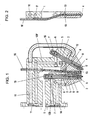
- a receptacle 1 which consists of an electrical insulating material is made.
- this shot 1 are two holders 2, at the lower ends of electrodes 3, 4 a temperature-resistant material such as Tungsten, used.
- the holder 2 are made of an electrically highly conductive Material made and are with a central bore 5th provided that in the upper and lower area via radial Bores 6 are connected to chambers 7, 8, of which the Chambers 7, each with a gas channel 109, 109 ', via the plasma gas is fed separately, are connected, and the chambers 8 with one outflow nozzle 9 9 'are connected.
- nozzles 9, 9 have conical inner walls, the inner wall of the nozzle 9 being substantially parallel to the tapered end portion of the electrode 3, the free End of the electrode 3 can be flattened.
- the electrode 4 is in contrast to the electrode 3 essentially blunt educated.
- cooling channel 10 in the receptacle 1 provided that of an inlet 11 to one of the holder 2 of the Electrode 4 penetrates and divided by annular space 12 in two branch channels (Fig. 2) to another from the holder 2 of the Electrode 3 passes through annular space 13 and from this to one Spout 14 leads.
- connection of the two electrodes 3, 4, or their holder 2 can screw caps 15, or if the Gas channels 109, 109 'have electrically conductive walls, about these are done. In the latter case, the connection can be made via Connection nipples via which gas is supplied are made.
- a tubular guide 16 between the nozzles 9, 9 ' provided that to serve as an additional material Wire is provided.
- the guide 16 is cranked out.
- the recording 1 be made very narrow.
- the electrode 3 runs in the position of use of the receptacle 1 in essentially vertical and the electrode 4 closes with this an acute angle which is usually 20 ° to 70 ° can.
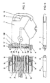
- connection head 18 In this connection head 18 are spring-loaded Nipple 20 held axially displaceable, one of which Water supply line 21 and a water discharge line 22 for supply and Removal of cooling water are connected, this spring-loaded connecting nipple 20 when the receptacle is connected 1 engage in the inlet or outlet 11, 14 of the same. Furthermore, 18 are fixed connection nipples 23 in this connection head provided on which plasma gas, e.g. Helium, leading Gas lines 24 are connected. The fixed Connection nipples 23 engage with the receptacle 1 connected Inlets 25 of the gas channels 109, 109 'of the receptacle 1. there are, as with the inlet and outlet 11, 14 in the inlets 25 O-rings used for sealing.
- plasma gas e.g. Helium
- connection head 18 arranged pin 26 held in a corresponding Bore 27 engages a receptacle 1. This is ensured that a connection of a recording 1 to the Connection head only in a certain position, in which one correct flow through the gas and cooling channels is given, is possible.
- connection head 18 can with different Electrodes 3, 4 equipped receptacles 1 are connected, such a change can be carried out very easily can.
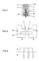
- FIG. 7 shows a detail of the nozzle body 9 for an electrode 3, which is a conical, or substantially has a frustoconical end.
- the plasma gas flowing through these cold gas channels causes cooling of the nozzle body 9 and causes a further constriction of the exiting from the nozzle 9 Plasma and thus a reduction in the focal spot and thus an increase in energy concentration in this.
- the Chamber 8 is supplied with plasma gas via a Gas channel 109, 109 ', the upper radial bores 6 of the holder 2, its central bore 5 and the lower radial bores 6th
- Fig. 8 shows schematically the connection of the device according to the invention.
- the electrodes 3, 4 with one pole each, one voltage source 31, 32 connected, the respective second pole of each of which has a switching device 33, 34 is connected to a workpiece 30.
- the two switching devices 33, 34 locked against each other so that only one Switching device 33 or 34 can be switched through. There are only short for the two switching devices 33, 34 Switching times are provided so that the electrodes 3, 4 only impulsed.
- Typical values are e.g. a Current application of approx. 170 A for a time of approx. 15ms and a pause of approx. 3ms. During this time switches the switching device 33 through and with the plus pole Electrode 4 connecting current source 31 is approx. 250 A for about 3ms applied.
- Insert 1 insert two electrodes 3 and both with the Minus pole each to connect a DC voltage source 32 and to apply these essentially alternately, whereby however, overlap times can also be provided. There on this way the load of each electrode 3 accordingly is small, electrodes 3 with a small diameter can be used be made, which makes the recording very narrow can.
- the embodiment according to FIG. 10 differs from that according to FIGS. 1 and 2 in that in the over the gas channels 109, 109 'in connection with the gas connections standing chambers 8 helical ribs 35 are arranged between which are helical channels remain, via which the plasma gas flows to the nozzles 9, 9 '.
Landscapes
- Physics & Mathematics (AREA)
- Engineering & Computer Science (AREA)
- Plasma & Fusion (AREA)
- Spectroscopy & Molecular Physics (AREA)
- Plasma Technology (AREA)
- Arc Welding In General (AREA)
Priority Applications (1)
| Application Number | Priority Date | Filing Date | Title |
|---|---|---|---|
| AT01890189T ATE335565T1 (de) | 2000-06-21 | 2001-06-19 | Plasmabrenner |
Applications Claiming Priority (2)
| Application Number | Priority Date | Filing Date | Title |
|---|---|---|---|
| AT0045300U AT4667U1 (de) | 2000-06-21 | 2000-06-21 | Plasmabrenner |
| AT4532000 | 2000-06-21 |
Publications (3)
| Publication Number | Publication Date |
|---|---|
| EP1166942A2 true EP1166942A2 (fr) | 2002-01-02 |
| EP1166942A3 EP1166942A3 (fr) | 2004-01-02 |
| EP1166942B1 EP1166942B1 (fr) | 2006-08-09 |
Family
ID=3491008
Family Applications (1)
| Application Number | Title | Priority Date | Filing Date |
|---|---|---|---|
| EP01890189A Expired - Lifetime EP1166942B1 (fr) | 2000-06-21 | 2001-06-19 | Torche plasma |
Country Status (4)
| Country | Link |
|---|---|
| US (1) | US6410879B1 (fr) |
| EP (1) | EP1166942B1 (fr) |
| AT (1) | AT4667U1 (fr) |
| CA (1) | CA2350977C (fr) |
Cited By (1)
| Publication number | Priority date | Publication date | Assignee | Title |
|---|---|---|---|---|
| CN101434000B (zh) * | 2008-12-13 | 2011-03-23 | 东方电气集团东方汽轮机有限公司 | 小内径深孔等离子喷焊枪 |
Families Citing this family (2)
| Publication number | Priority date | Publication date | Assignee | Title |
|---|---|---|---|---|
| US9233432B2 (en) * | 2007-02-12 | 2016-01-12 | Yu Ming Zhang | Arc welder and related system |
| US9831070B1 (en) | 2017-06-15 | 2017-11-28 | Enercon Industries Corporation | Surface treater with expansion electrode arrangement |
Citations (8)
| Publication number | Priority date | Publication date | Assignee | Title |
|---|---|---|---|---|
| GB691373A (en) * | 1950-04-28 | 1953-05-13 | Gen Electric Co Ltd | Improvements in and relating to processes for electric arc welding and to apparatus for carrying out such processes |
| FR2062768A5 (en) * | 1969-10-01 | 1971-06-25 | British Railways Board | Plasma torch |
| FR2229493A1 (en) * | 1973-05-16 | 1974-12-13 | Pk Tekhno | Strip welding twin nozzle plasma gun - with opposed alternately pulsed current in either nozzle |
| GB1384730A (fr) * | 1971-11-19 | 1975-02-19 | Rikagaku Kenkyusho Plasma Jet | |
| US3931489A (en) * | 1973-11-05 | 1976-01-06 | Kabel-Und Metallwerke Gutehoffnungshuette Aktiengesellschaft | Multiarc seam welding apparatus for thin metal sheet |
| US4107507A (en) * | 1973-06-06 | 1978-08-15 | L'air Liquide Societe Anonyme Pour L'etude Et L'exploitation Des Procedes Georges Claude | Arc welding process and apparatus |
| US4119828A (en) * | 1977-02-08 | 1978-10-10 | Vsesojuzny Nauchno-Issledovatelsky Proektno-Konstruktorsky I Tekhnologichesky Institut Elektrosvarochnogo Oborudovania | Method of plasma multiarc welding by permanently burning direct-current arcs |
| US5332885A (en) * | 1991-02-21 | 1994-07-26 | Plasma Technik Ag | Plasma spray apparatus for spraying powdery or gaseous material |
Family Cites Families (5)
| Publication number | Priority date | Publication date | Assignee | Title |
|---|---|---|---|---|
| DE2926210A1 (de) | 1979-06-29 | 1981-02-12 | Maschf Augsburg Nuernberg Ag | Verfahren und vorrichtung zum elektrischen lichtbogenschweissen |
| US5798497A (en) * | 1995-02-02 | 1998-08-25 | Battelle Memorial Institute | Tunable, self-powered integrated arc plasma-melter vitrification system for waste treatment and resource recovery |
| WO1996039794A1 (fr) * | 1995-06-05 | 1996-12-12 | Tohoku Unicom Co., Ltd. | Alimentation servant a une decharge par electrodes multiples |
| JPH11117845A (ja) | 1997-10-11 | 1999-04-27 | Masahide Ichikawa | 内燃機関に於ける複数点火パルス発生回路 |
| US6121571A (en) * | 1999-12-16 | 2000-09-19 | Trusi Technologies Llc | Plasma generator ignition circuit |
-
2000
- 2000-06-21 AT AT0045300U patent/AT4667U1/de not_active IP Right Cessation
-
2001
- 2001-06-18 US US09/883,412 patent/US6410879B1/en not_active Expired - Fee Related
- 2001-06-19 EP EP01890189A patent/EP1166942B1/fr not_active Expired - Lifetime
- 2001-06-20 CA CA002350977A patent/CA2350977C/fr not_active Expired - Fee Related
Patent Citations (8)
| Publication number | Priority date | Publication date | Assignee | Title |
|---|---|---|---|---|
| GB691373A (en) * | 1950-04-28 | 1953-05-13 | Gen Electric Co Ltd | Improvements in and relating to processes for electric arc welding and to apparatus for carrying out such processes |
| FR2062768A5 (en) * | 1969-10-01 | 1971-06-25 | British Railways Board | Plasma torch |
| GB1384730A (fr) * | 1971-11-19 | 1975-02-19 | Rikagaku Kenkyusho Plasma Jet | |
| FR2229493A1 (en) * | 1973-05-16 | 1974-12-13 | Pk Tekhno | Strip welding twin nozzle plasma gun - with opposed alternately pulsed current in either nozzle |
| US4107507A (en) * | 1973-06-06 | 1978-08-15 | L'air Liquide Societe Anonyme Pour L'etude Et L'exploitation Des Procedes Georges Claude | Arc welding process and apparatus |
| US3931489A (en) * | 1973-11-05 | 1976-01-06 | Kabel-Und Metallwerke Gutehoffnungshuette Aktiengesellschaft | Multiarc seam welding apparatus for thin metal sheet |
| US4119828A (en) * | 1977-02-08 | 1978-10-10 | Vsesojuzny Nauchno-Issledovatelsky Proektno-Konstruktorsky I Tekhnologichesky Institut Elektrosvarochnogo Oborudovania | Method of plasma multiarc welding by permanently burning direct-current arcs |
| US5332885A (en) * | 1991-02-21 | 1994-07-26 | Plasma Technik Ag | Plasma spray apparatus for spraying powdery or gaseous material |
Cited By (1)
| Publication number | Priority date | Publication date | Assignee | Title |
|---|---|---|---|---|
| CN101434000B (zh) * | 2008-12-13 | 2011-03-23 | 东方电气集团东方汽轮机有限公司 | 小内径深孔等离子喷焊枪 |
Also Published As
| Publication number | Publication date |
|---|---|
| US6410879B1 (en) | 2002-06-25 |
| AT4667U1 (de) | 2001-10-25 |
| CA2350977C (fr) | 2009-05-12 |
| EP1166942B1 (fr) | 2006-08-09 |
| CA2350977A1 (fr) | 2001-12-21 |
| US20020033386A1 (en) | 2002-03-21 |
| EP1166942A3 (fr) | 2004-01-02 |
Similar Documents
| Publication | Publication Date | Title |
|---|---|---|
| EP0955120B1 (fr) | Méthode et appareillage pour la fusion partielle d'objets | |
| DE69020885T2 (de) | Plasmabogenbrenner mit langer Düse. | |
| DE1244627B (de) | Plasma-Spritzvorrichtung | |
| EP2483031B1 (fr) | Procédé de découpage au plasma d'une pièce au moyen d'une installation de découpage au plasma et d'un courant pulsé | |
| DE102016010341A1 (de) | Plasmabrenner und komponenten des plasmabrenners | |
| DE4407913A1 (de) | Plasmabrenner und Verfahren zur Durchführung, insbesondere für das Aushöhlen von Werkstücken | |
| EP0134961B1 (fr) | Torche à plasma et méthode de fonctionnement | |
| DE2654144A1 (de) | Verfahren und brenner zum aufrechterhalten von koaxialen mehrfachlichtboegen | |
| DE2511204A1 (de) | Verfahren und vorrichtung zum lichtbogenschweissen | |
| DE69901731T2 (de) | Aus kupfer-legierung hergestelltes verschleissteil für lichtbogenbrenner | |
| EP1166942A2 (fr) | Torche plasma | |
| DE112015005021B4 (de) | Lichtbogenschweißgerät | |
| DE3542984A1 (de) | Verfahren und einrichtung zum teil- oder vollmechanisierten schutzgas-verbindungsschweissen | |
| DE1440423B1 (de) | Vorrichtung und verfahren zum kontinuierlichen reinigen der oberflaeche eines in langgestreckter form vorliegenden elektrisch leitenden werkstuecks | |
| DE2545495C2 (de) | Plasma-Brenner | |
| DE102007017224A1 (de) | Verfahren zum Plasma-Stichlochschweißen | |
| DE10129965A1 (de) | Verfahren und Einrichtung zum Schweißen | |
| DE1440623B1 (de) | Schutzgas-Lichtbogenbrenner | |
| DE2813804A1 (de) | Plasmabogen schweiss- und schneidgeraet | |
| AT406243B (de) | Gerät mit einem plasmaerzeuger | |
| DE1515246A1 (de) | Verfahren und Vorrichtung zur Herstellung von Schweissnaehten bei hoher Schweissgeschwindigkeit unter Verwendung mehrerer Lichtboegen | |
| DE2513090C2 (de) | Verfahren zum Plasma- MIG-Schweißen | |
| DE4120791A1 (de) | Anordnung zum oberflaechenbehandeln metallischer werkstuecke | |
| WO2019053055A1 (fr) | Chalumeau tig de soudage, brasage ou revêtement | |
| DE102014013047A1 (de) | Schweißbrenner und Schweißverfahren mit ringförmiger Elektrodenanordnung |
Legal Events
| Date | Code | Title | Description |
|---|---|---|---|
| PUAI | Public reference made under article 153(3) epc to a published international application that has entered the european phase |
Free format text: ORIGINAL CODE: 0009012 |
|
| AK | Designated contracting states |
Kind code of ref document: A2 Designated state(s): AT BE CH CY DE DK ES FI FR GB GR IE IT LI LU MC NL PT SE TR |
|
| AX | Request for extension of the european patent |
Free format text: AL;LT;LV;MK;RO;SI |
|
| PUAL | Search report despatched |
Free format text: ORIGINAL CODE: 0009013 |
|
| AK | Designated contracting states |
Kind code of ref document: A3 Designated state(s): AT BE CH CY DE DK ES FI FR GB GR IE IT LI LU MC NL PT SE TR |
|
| AX | Request for extension of the european patent |
Extension state: AL LT LV MK RO SI |
|
| RIC1 | Information provided on ipc code assigned before grant |
Ipc: 7B 23K 10/00 A Ipc: 7B 23K 10/02 B Ipc: 7H 05H 1/44 B |
|
| 17P | Request for examination filed |
Effective date: 20040618 |
|
| AKX | Designation fees paid |
Designated state(s): AT BE CH CY DE DK ES FI FR GB GR IE IT LI LU MC NL PT SE TR |
|
| 17Q | First examination report despatched |
Effective date: 20050309 |
|
| GRAP | Despatch of communication of intention to grant a patent |
Free format text: ORIGINAL CODE: EPIDOSNIGR1 |
|
| GRAS | Grant fee paid |
Free format text: ORIGINAL CODE: EPIDOSNIGR3 |
|
| GRAA | (expected) grant |
Free format text: ORIGINAL CODE: 0009210 |
|
| AK | Designated contracting states |
Kind code of ref document: B1 Designated state(s): AT BE CH CY DE DK ES FI FR GB GR IE IT LI LU MC NL PT SE TR |
|
| PG25 | Lapsed in a contracting state [announced via postgrant information from national office to epo] |
Ref country code: IT Free format text: LAPSE BECAUSE OF FAILURE TO SUBMIT A TRANSLATION OF THE DESCRIPTION OR TO PAY THE FEE WITHIN THE PRESCRIBED TIME-LIMIT;WARNING: LAPSES OF ITALIAN PATENTS WITH EFFECTIVE DATE BEFORE 2007 MAY HAVE OCCURRED AT ANY TIME BEFORE 2007. THE CORRECT EFFECTIVE DATE MAY BE DIFFERENT FROM THE ONE RECORDED. Effective date: 20060809 Ref country code: FI Free format text: LAPSE BECAUSE OF FAILURE TO SUBMIT A TRANSLATION OF THE DESCRIPTION OR TO PAY THE FEE WITHIN THE PRESCRIBED TIME-LIMIT Effective date: 20060809 Ref country code: GB Free format text: LAPSE BECAUSE OF FAILURE TO SUBMIT A TRANSLATION OF THE DESCRIPTION OR TO PAY THE FEE WITHIN THE PRESCRIBED TIME-LIMIT Effective date: 20060809 Ref country code: IE Free format text: LAPSE BECAUSE OF FAILURE TO SUBMIT A TRANSLATION OF THE DESCRIPTION OR TO PAY THE FEE WITHIN THE PRESCRIBED TIME-LIMIT Effective date: 20060809 Ref country code: NL Free format text: LAPSE BECAUSE OF FAILURE TO SUBMIT A TRANSLATION OF THE DESCRIPTION OR TO PAY THE FEE WITHIN THE PRESCRIBED TIME-LIMIT Effective date: 20060809 |
|
| REG | Reference to a national code |
Ref country code: GB Ref legal event code: FG4D Free format text: NOT ENGLISH |
|
| REG | Reference to a national code |
Ref country code: CH Ref legal event code: EP |
|
| REG | Reference to a national code |
Ref country code: IE Ref legal event code: FG4D Free format text: LANGUAGE OF EP DOCUMENT: GERMAN |
|
| REF | Corresponds to: |
Ref document number: 50110663 Country of ref document: DE Date of ref document: 20060921 Kind code of ref document: P |
|
| PG25 | Lapsed in a contracting state [announced via postgrant information from national office to epo] |
Ref country code: SE Free format text: LAPSE BECAUSE OF FAILURE TO SUBMIT A TRANSLATION OF THE DESCRIPTION OR TO PAY THE FEE WITHIN THE PRESCRIBED TIME-LIMIT Effective date: 20061109 Ref country code: DK Free format text: LAPSE BECAUSE OF FAILURE TO SUBMIT A TRANSLATION OF THE DESCRIPTION OR TO PAY THE FEE WITHIN THE PRESCRIBED TIME-LIMIT Effective date: 20061109 |
|
| PG25 | Lapsed in a contracting state [announced via postgrant information from national office to epo] |
Ref country code: ES Free format text: LAPSE BECAUSE OF FAILURE TO SUBMIT A TRANSLATION OF THE DESCRIPTION OR TO PAY THE FEE WITHIN THE PRESCRIBED TIME-LIMIT Effective date: 20061120 |
|
| PG25 | Lapsed in a contracting state [announced via postgrant information from national office to epo] |
Ref country code: PT Free format text: LAPSE BECAUSE OF FAILURE TO SUBMIT A TRANSLATION OF THE DESCRIPTION OR TO PAY THE FEE WITHIN THE PRESCRIBED TIME-LIMIT Effective date: 20070109 |
|
| NLV1 | Nl: lapsed or annulled due to failure to fulfill the requirements of art. 29p and 29m of the patents act | ||
| GBV | Gb: ep patent (uk) treated as always having been void in accordance with gb section 77(7)/1977 [no translation filed] |
Effective date: 20060809 |
|
| ET | Fr: translation filed | ||
| REG | Reference to a national code |
Ref country code: IE Ref legal event code: FD4D |
|
| PLBE | No opposition filed within time limit |
Free format text: ORIGINAL CODE: 0009261 |
|
| STAA | Information on the status of an ep patent application or granted ep patent |
Free format text: STATUS: NO OPPOSITION FILED WITHIN TIME LIMIT |
|
| 26N | No opposition filed |
Effective date: 20070510 |
|
| BERE | Be: lapsed |
Owner name: INOCON TECHNOLOGIE -G. M.B.H Effective date: 20070630 |
|
| PG25 | Lapsed in a contracting state [announced via postgrant information from national office to epo] |
Ref country code: MC Free format text: LAPSE BECAUSE OF NON-PAYMENT OF DUE FEES Effective date: 20070630 |
|
| REG | Reference to a national code |
Ref country code: CH Ref legal event code: PL |
|
| PG25 | Lapsed in a contracting state [announced via postgrant information from national office to epo] |
Ref country code: BE Free format text: LAPSE BECAUSE OF NON-PAYMENT OF DUE FEES Effective date: 20070630 |
|
| PG25 | Lapsed in a contracting state [announced via postgrant information from national office to epo] |
Ref country code: LI Free format text: LAPSE BECAUSE OF NON-PAYMENT OF DUE FEES Effective date: 20070630 Ref country code: CH Free format text: LAPSE BECAUSE OF NON-PAYMENT OF DUE FEES Effective date: 20070630 Ref country code: GR Free format text: LAPSE BECAUSE OF FAILURE TO SUBMIT A TRANSLATION OF THE DESCRIPTION OR TO PAY THE FEE WITHIN THE PRESCRIBED TIME-LIMIT Effective date: 20061110 |
|
| PG25 | Lapsed in a contracting state [announced via postgrant information from national office to epo] |
Ref country code: CY Free format text: LAPSE BECAUSE OF FAILURE TO SUBMIT A TRANSLATION OF THE DESCRIPTION OR TO PAY THE FEE WITHIN THE PRESCRIBED TIME-LIMIT Effective date: 20060809 Ref country code: LU Free format text: LAPSE BECAUSE OF NON-PAYMENT OF DUE FEES Effective date: 20070619 |
|
| PGFP | Annual fee paid to national office [announced via postgrant information from national office to epo] |
Ref country code: FR Payment date: 20090520 Year of fee payment: 9 |
|
| PG25 | Lapsed in a contracting state [announced via postgrant information from national office to epo] |
Ref country code: TR Free format text: LAPSE BECAUSE OF FAILURE TO SUBMIT A TRANSLATION OF THE DESCRIPTION OR TO PAY THE FEE WITHIN THE PRESCRIBED TIME-LIMIT Effective date: 20060809 |
|
| PGFP | Annual fee paid to national office [announced via postgrant information from national office to epo] |
Ref country code: DE Payment date: 20090730 Year of fee payment: 9 |
|
| REG | Reference to a national code |
Ref country code: FR Ref legal event code: ST Effective date: 20110228 |
|
| PG25 | Lapsed in a contracting state [announced via postgrant information from national office to epo] |
Ref country code: DE Free format text: LAPSE BECAUSE OF NON-PAYMENT OF DUE FEES Effective date: 20110101 |
|
| PG25 | Lapsed in a contracting state [announced via postgrant information from national office to epo] |
Ref country code: FR Free format text: LAPSE BECAUSE OF NON-PAYMENT OF DUE FEES Effective date: 20100630 |
|
| PGFP | Annual fee paid to national office [announced via postgrant information from national office to epo] |
Ref country code: AT Payment date: 20151223 Year of fee payment: 15 |
|
| REG | Reference to a national code |
Ref country code: AT Ref legal event code: MM01 Ref document number: 335565 Country of ref document: AT Kind code of ref document: T Effective date: 20160619 |
|
| PG25 | Lapsed in a contracting state [announced via postgrant information from national office to epo] |
Ref country code: AT Free format text: LAPSE BECAUSE OF NON-PAYMENT OF DUE FEES Effective date: 20160619 |