EP1166942A2 - Plasma gun - Google Patents
Plasma gun Download PDFInfo
- Publication number
- EP1166942A2 EP1166942A2 EP01890189A EP01890189A EP1166942A2 EP 1166942 A2 EP1166942 A2 EP 1166942A2 EP 01890189 A EP01890189 A EP 01890189A EP 01890189 A EP01890189 A EP 01890189A EP 1166942 A2 EP1166942 A2 EP 1166942A2
- Authority
- EP
- European Patent Office
- Prior art keywords
- electrode
- nozzle
- pole
- voltage source
- rod
- Prior art date
- Legal status (The legal status is an assumption and is not a legal conclusion. Google has not performed a legal analysis and makes no representation as to the accuracy of the status listed.)
- Granted
Links
Images


Classifications
-
- H—ELECTRICITY
- H05—ELECTRIC TECHNIQUES NOT OTHERWISE PROVIDED FOR
- H05H—PLASMA TECHNIQUE; PRODUCTION OF ACCELERATED ELECTRICALLY-CHARGED PARTICLES OR OF NEUTRONS; PRODUCTION OR ACCELERATION OF NEUTRAL MOLECULAR OR ATOMIC BEAMS
- H05H1/00—Generating plasma; Handling plasma
- H05H1/24—Generating plasma
- H05H1/26—Plasma torches
- H05H1/32—Plasma torches using an arc
- H05H1/44—Plasma torches using an arc using more than one torch
Definitions
- the invention relates to a device according to the preamble of claim 1.
- the aim of the invention is to overcome these disadvantages avoid and a facility of the type mentioned propose a high welding speed even when allows difficult alloys and with that too it can be ensured that oxide layers formed be removed.
- the proposed measures make it possible the two rod-shaped electrodes with different poles to connect the voltage sources. This allows you to Plasma pulses with one with the plus pole one Electrode connected to the voltage source are generated Oxide layers ripped open and with the following Plasma pulses with the one with the negative pole Voltage source connected and therefore connected as a cathode Electrode are generated, the base material clean and with large penetration depth are welded, whereby very result in narrow and smooth seams. It can be done with a very high welding speed. Through the Locking the switching devices, each only Allow voltage pulses of approximately 1 to 5 milliseconds ensured that only one electrode was applied at a time can be.
- Each plasma arc can be ignited by means of a high frequency pulse occur when the level of voltage the individual voltage pulses Breakdown voltage of the distance between the electrode and their respective counterelectrode.
- the ignition but can also by correspondingly high, the respective Breakdown voltage exceeding voltage pulses themselves to be triggered.
- claims 9 and 11 effect one Constriction of the plasma, or avoid expanding it due to the friction of the plasma in the air with escapes at high speed, so that a very high concentration the energy is achieved.
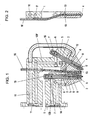
- a receptacle 1 which consists of an electrical insulating material is made.
- this shot 1 are two holders 2, at the lower ends of electrodes 3, 4 a temperature-resistant material such as Tungsten, used.
- the holder 2 are made of an electrically highly conductive Material made and are with a central bore 5th provided that in the upper and lower area via radial Bores 6 are connected to chambers 7, 8, of which the Chambers 7, each with a gas channel 109, 109 ', via the plasma gas is fed separately, are connected, and the chambers 8 with one outflow nozzle 9 9 'are connected.
- nozzles 9, 9 have conical inner walls, the inner wall of the nozzle 9 being substantially parallel to the tapered end portion of the electrode 3, the free End of the electrode 3 can be flattened.
- the electrode 4 is in contrast to the electrode 3 essentially blunt educated.
- cooling channel 10 in the receptacle 1 provided that of an inlet 11 to one of the holder 2 of the Electrode 4 penetrates and divided by annular space 12 in two branch channels (Fig. 2) to another from the holder 2 of the Electrode 3 passes through annular space 13 and from this to one Spout 14 leads.
- connection of the two electrodes 3, 4, or their holder 2 can screw caps 15, or if the Gas channels 109, 109 'have electrically conductive walls, about these are done. In the latter case, the connection can be made via Connection nipples via which gas is supplied are made.
- a tubular guide 16 between the nozzles 9, 9 ' provided that to serve as an additional material Wire is provided.
- the guide 16 is cranked out.
- the recording 1 be made very narrow.
- the electrode 3 runs in the position of use of the receptacle 1 in essentially vertical and the electrode 4 closes with this an acute angle which is usually 20 ° to 70 ° can.
- connection head 18 In this connection head 18 are spring-loaded Nipple 20 held axially displaceable, one of which Water supply line 21 and a water discharge line 22 for supply and Removal of cooling water are connected, this spring-loaded connecting nipple 20 when the receptacle is connected 1 engage in the inlet or outlet 11, 14 of the same. Furthermore, 18 are fixed connection nipples 23 in this connection head provided on which plasma gas, e.g. Helium, leading Gas lines 24 are connected. The fixed Connection nipples 23 engage with the receptacle 1 connected Inlets 25 of the gas channels 109, 109 'of the receptacle 1. there are, as with the inlet and outlet 11, 14 in the inlets 25 O-rings used for sealing.
- plasma gas e.g. Helium
- connection head 18 arranged pin 26 held in a corresponding Bore 27 engages a receptacle 1. This is ensured that a connection of a recording 1 to the Connection head only in a certain position, in which one correct flow through the gas and cooling channels is given, is possible.
- connection head 18 can with different Electrodes 3, 4 equipped receptacles 1 are connected, such a change can be carried out very easily can.
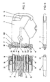
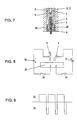
- FIG. 7 shows a detail of the nozzle body 9 for an electrode 3, which is a conical, or substantially has a frustoconical end.
- the plasma gas flowing through these cold gas channels causes cooling of the nozzle body 9 and causes a further constriction of the exiting from the nozzle 9 Plasma and thus a reduction in the focal spot and thus an increase in energy concentration in this.
- the Chamber 8 is supplied with plasma gas via a Gas channel 109, 109 ', the upper radial bores 6 of the holder 2, its central bore 5 and the lower radial bores 6th
- Fig. 8 shows schematically the connection of the device according to the invention.
- the electrodes 3, 4 with one pole each, one voltage source 31, 32 connected, the respective second pole of each of which has a switching device 33, 34 is connected to a workpiece 30.
- the two switching devices 33, 34 locked against each other so that only one Switching device 33 or 34 can be switched through. There are only short for the two switching devices 33, 34 Switching times are provided so that the electrodes 3, 4 only impulsed.
- Typical values are e.g. a Current application of approx. 170 A for a time of approx. 15ms and a pause of approx. 3ms. During this time switches the switching device 33 through and with the plus pole Electrode 4 connecting current source 31 is approx. 250 A for about 3ms applied.
- Insert 1 insert two electrodes 3 and both with the Minus pole each to connect a DC voltage source 32 and to apply these essentially alternately, whereby however, overlap times can also be provided. There on this way the load of each electrode 3 accordingly is small, electrodes 3 with a small diameter can be used be made, which makes the recording very narrow can.
- the embodiment according to FIG. 10 differs from that according to FIGS. 1 and 2 in that in the over the gas channels 109, 109 'in connection with the gas connections standing chambers 8 helical ribs 35 are arranged between which are helical channels remain, via which the plasma gas flows to the nozzles 9, 9 '.
Landscapes
- Physics & Mathematics (AREA)
- Engineering & Computer Science (AREA)
- Plasma & Fusion (AREA)
- Spectroscopy & Molecular Physics (AREA)
- Plasma Technology (AREA)
- Arc Welding In General (AREA)
Abstract
Description
Die Erfindung bezieht sich auf eine Einrichtung gemäß
dem Oberbegriff des Anspruches 1.The invention relates to a device according to
the preamble of
Bei der Schweißung von Leichtmetall und Leichtmetall-Legierungen wird eine Einrichtung der eingangs erwähnten Art mit lediglich einer stabfömigen Elektrode verwendet. Um eine hohe Schweißgeschwindigkeit bei tiefem Einbrand und schmalen Nähten zu erzielen, wird die stabförmige Elektrode als Kathode geschaltet und als Plasmagas Helium verwendet. Dabei entsteht ein sehr heißes Plasma, das dünne Oxidschichten verdampft. Allerdings ist die nicht bei allen Leichtmetall-Legierungen der Fall.When welding light metal and light metal alloys a device of the type mentioned used with only one rod-shaped electrode. To one high welding speed with deep penetration and narrow To achieve seams, the rod-shaped electrode is used as the cathode switched and used as plasma gas helium. This creates a very hot plasma that evaporates thin layers of oxide. Indeed is not the case with all light metal alloys Case.
Um auch solche Legierungen schweißen zu können, wird meist statt mit Gleichstrom mit Wechselstrom geschweißt, oder es wird die Elektrode an den Plus-Pol der Spannungsquelle gelegt. Damit wird zwar eine ständige Beseitigung der Oxidschichten sichergestellt und eine lunkerfreie Schweißverbindung ermöglicht, da die Oxidhaut ständig aufgerissen wird, doch steht diesem Vorteil der Nachteil einer um ca. 2/3 verminderten Schweißgeschwindigleit, verglichen mit einer Gleichstrom/Helium-Schweißung und eine deutliche Zunahme der Breite der Schweißnähte mit vergrößerter Wärmeeinflußzone gegenüber.In order to be able to weld such alloys, too usually welded with alternating current instead of direct current, or it becomes the electrode at the plus pole of the voltage source placed. This will mean that the Oxide layers ensured and a void-free Welded connection allows because the oxide skin is constantly is torn open, but this advantage is the disadvantage of one welding speed reduced by approx. 2/3 compared to a DC / helium weld and a significant increase the width of the welds with an enlarged heat affected zone across from.
Ziel der Erfindung ist es, diese Nachteile zu vermeiden und eine Einrichtung der eingangs erwähnten Art vorzuschlagen, die eine hohe Schweißgeschwindigkeit auch bei schwierigen Legierungen ermöglicht und mit der auch sichergestellt werden kann, daß entstehende Oxidschichten entfernt werden.The aim of the invention is to overcome these disadvantages avoid and a facility of the type mentioned propose a high welding speed even when allows difficult alloys and with that too it can be ensured that oxide layers formed be removed.
Erfindungsgemäß wird dies bei einer Einrichtung der
eingangs erwähnten Art durch die kennzeichnenden Merkmale des
Anspruches 1 erreicht.According to the invention, this is achieved with a device
type mentioned above by the characteristic features of the
Durch die vorgeschlagenen Maßnahmen ist es möglich die beiden stabförmigen Elektroden mit unterschiedlichen Polen der Spannungsquellen zu verbinden. Dadurch können mit Plasmaimpulsen, die mit einer mit dem Plus-Pol einer Spannungsquelle verbundenen Elektrode erzeugt werden, die Oxidschichten aufgerissen und mit den nachfolgenden Plasmaimpulsen, die mit der mit dem Minuspol einer Spannungsquelle verbundenen und daher als Kathode geschalteten Elektrode erzeugt werden, das Grundmaterial sauber und mit großer Einbrandtiefe verschweißt werden, wobei sich sehr schmale und glatte Nähte ergeben. Dabei kann mit einer sehr hohen Schweißgeschwindigleit gearbeitet werden. Durch die Verriegelung der Schalteinrichtungen, die jeweils nur Spannungsimpulse von ca. 1 bis 5 Millisekunden zulassen, ist sichergestellt, daß nur jeweils eine Elektrode beaufschlagt werden kann.The proposed measures make it possible the two rod-shaped electrodes with different poles to connect the voltage sources. This allows you to Plasma pulses with one with the plus pole one Electrode connected to the voltage source are generated Oxide layers ripped open and with the following Plasma pulses with the one with the negative pole Voltage source connected and therefore connected as a cathode Electrode are generated, the base material clean and with large penetration depth are welded, whereby very result in narrow and smooth seams. It can be done with a very high welding speed. Through the Locking the switching devices, each only Allow voltage pulses of approximately 1 to 5 milliseconds ensured that only one electrode was applied at a time can be.
Als Gegenelektrode kann zweckmäßigerweise das zu bearbeitende Werkstück geschaltet werden, doch ist es auch möglich, die Düse, bzw. den jeweiligen Düsenkörper aus einem elektrisch leitenden Material herzustellen und als Gegenelektrode zu schalten.This can expediently serve as the counter electrode machining workpiece can be switched, but it is also possible, the nozzle, or the respective nozzle body from one produce electrically conductive material and as To switch counter electrode.
Bei leichter schweißbaren Legierungen können auch beide Elektroden als Kathoden geschaltet werden. In diesem Fall ergibt sich der Vorteil, daß die erforderliche Schweißenergie auf beide Elektroden aufgeteilt werden kann und diese daher dünner ausgebildet werden können. Dies ermöglicht die Herstellung sehr schmaler Aufnahmen von z.B. nur 9mm Breite. Mit solchen Einrichtungen kann daher auch in nur schwer zugänglichen Eckbereichen von Werkstücken geschweißt werden, was die konstruktive Auslegung solcher Teile wesentlich erleichtert.With more easily weldable alloys, too both electrodes are switched as cathodes. In this case there is the advantage that the required welding energy can be divided between both electrodes and therefore these can be made thinner. This enables production very narrow recordings of e.g. only 9mm wide. With Such facilities can therefore also be difficult to access Corner areas of workpieces are welded to what the constructive design of such parts much easier.
Aufgrund der beiden getrennten Spannungsquellen, können diese auch im Hinblick auf die Impulslänge und Impulsleistung getrennt gesteuert werden, wodurch eine sehr weitgehende Anpassung an die jeweiligen Erfordernisse möglich ist.Because of the two separate voltage sources, can this also with regard to the pulse length and Pulse power can be controlled separately, creating a very extensive adaptation to the respective requirements possible is.
Die Zündung eines jeden Plasmabogens kann mittels eines Hochfrequenzimpulses erfolgen, wenn die Höhe der Spannung der einzelnen Spannungsimpulse die jeweilige Durchschlagsspannung der Strecke zwischen der Elektrode und ihrer jeweiligen Gegenelektrode nicht übersteigt. Die Zündung kann aber auch durch entsprechend hohe, die jeweilige Durchschlagsspannung übersteigende Spannungsimpulse selbst ausgelöst werden.Each plasma arc can be ignited by means of a high frequency pulse occur when the level of voltage the individual voltage pulses Breakdown voltage of the distance between the electrode and their respective counterelectrode. The ignition but can also by correspondingly high, the respective Breakdown voltage exceeding voltage pulses themselves to be triggered.
Sehr günstige Verhältnisse für das Schweißen sehr
schwieriger Legierungen ergeben sich durch die Merkmale des Anspruches
3, wobei es sich als vorteilhaft erwiesen hat auch die
Merkmale des Anspruches 2 vorzusehen, wobei die als Kathode
geschaltete Elektrode vorzugsweise im wesentlichen senkrecht
zum Werkstück steht. Very favorable conditions for welding very
Difficult alloys result from the features of the
Durch die Merkmale des Anspruches 4 kann der
Verschleiß der mit dem Plus-Pol verbundenen Elektrode, die
höher beansprucht wird, relativ gering gehalten werden.Due to the features of
Die Merkmale des Anspruches 5 ermöglichen einen
einfachen Aufbau der Aufnahme, wobei aber sichergestellt ist,
daß die höher belastete Elektrode entsprechend gut gekühlt
wird.The features of
Durch Maßnahmen gemäß dem Anspruch 6 kann eine
Ionisierung des aus der Düse ausströmenden Plasmagases im
Bereich zwischen der Elektrode und der Düse aufgrund eines HF-Überschlages
erreicht und damit die Zündung eines Lichtbogens
zwischen der Elektrode und dem Werkstück aufgrund der
angelegten Gleichspannung erreicht werden. Dabei ergibt sich
auch eine sehr weitgehende Schonung des Plasmabrenners, da
dieser nicht von dem sonst üblichen Pilotlichtbogen belastet
ist.By measures according to
Durch die Ionisierung aufgrund des HF-Überschlages, der die Düse thermisch nur sehr wenig beansprucht, ist es auch bei Verwendung von Helium als Plasmagas möglich, selbst über größere Abstände zwischen der Elektrode und dem Werkstück von z.B. 10mm problemlos zu zünden.By ionization due to the HF rollover, it does not put a great deal of thermal stress on the nozzle possible when using helium as plasma gas, even over larger distances between the electrode and the workpiece from e.g. Easy to ignite 10mm.
Die Verwendung einer aus einem elektrisch gut leitenden Material hergestellten Düse und deren Verbindung über einen hochohmigen elektrischen Widerstand mit dem mit dem Werkstück verbundenen Pol der Spannungsquelle ist auch bei erfindungsgemäßen Einrichtungen von Vorteil, bei denen der Pluspol der Spannungsquelle mit der die Düse durchsetzenden Elektrode verbunden ist.The use of an electrical good conductive material produced nozzle and their connection over a high-impedance electrical resistance with that with the Workpiece-connected pole of the voltage source is also at Devices according to the invention are advantageous in which the Positive pole of the voltage source with the one passing through the nozzle Electrode is connected.
Durch die Merkmale des Anspruches 8 kann eine solche
Einrichtung sehr universell eingesetzt werden.Due to the features of
Die Merkmale des Anspruches 9 und 11 bewirken eine
Einschnürung des Plasmas, bzw. vermeiden eine Aufweitung desselben
aufgrund der Reibung des Plasmas an der Luft, das mit
hoher Geschwindigkeit austritt, sodaß eine sehr hohe Konzentration
der Energie erreicht wird.The features of
Die Erfindung wird nun anhand der Zeichnung näher
erläutert. Dabei zeigen:
Bei der Ausführungsform nach den Fig. 1 und 2 ist
eine Aufnahme 1 vorgesehen, die aus einem elektrisch
isolierenden Material hergestellt ist. In dieser Aufnahme 1
sind zwei Halter 2, an deren unteren Enden Elektroden 3, 4 aus
einem temperaturbeständigen Material, wie z.B. Wolfram,
eingesetzt.In the embodiment according to FIGS. 1 and 2
a
Die Halter 2 sind aus einem elektrisch gut leitenden
Material hergestellt und sind mit einer zentralen Bohrung 5
versehen, die im oberen und unteren Bereich über radiale
Bohrungen 6 mit Kammern 7, 8 verbunden sind, von denen die
Kammern 7 mit je einem Gaskanal 109, 109', über die Plasmagas
getrennt zugeführt wird, verbunden sind, und die Kammern 8 mit
je einer Ausströmdüse 9 9' verbunden sind.The
Diese Düsen 9, 9' weisen kegelige Innenwände auf,
wobei die Innenwand der Düse 9 im wesentlichen parallel zum
kegeligen Endbereich der Elektrode 3 verläuft, wobei das freie
Ende der Elektrode 3 abgeflacht sein kann. Die Elektrode 4 ist
im Gegensatz zur Elektrode 3 im wesentlichen stumpf
ausgebildet.These
Weiters ist in der Aufnahme 1 ein Kühlkanal 10
vorgesehen, der von einem Zulauf 11 zu einem vom Halter 2 der
Elektrode 4 durchsetzten Ringraum 12 und von diesem, aufgeteilt
in zwei Zweigkanäle (Fig. 2) zu einem weiteren vom Halter 2 der
Elektrode 3 durchsetzten Ringraum 13 und von diesem zu einem
Auslauf 14 führt.Furthermore, there is a
Der elektrische Anschluß der beiden Elektroden 3, 4,
bzw. deren Halter 2 kann über Schraubkappen 15, oder falls die
Gaskanäle 109, 109' elektrisch leitende Wände aufweisen, über
diese erfolgen. Im letzteren Fall kann der Anschluß über
Anschlußnippel, über die Gas zugeführt wird, erfolgen.The electrical connection of the two
Bei der Ausführungsform nach den Fig. 1 und 2 ist
zwischen den Düsen 9, 9' eine rohrförmige Führung 16
vorgesehen, die zur Führung eines als Zusatzmaterial dienenden
Drahtes vorgesehen ist. Dabei ist die Führung 16 ausgekröpft.In the embodiment according to FIGS. 1 and 2
a
Wie aus der Fig. 2 zu ersehen ist, kann die Aufnahme
1 sehr schmal ausgebildet werden.As can be seen from Fig. 2, the
Bei der Ausführungsform nach der Fig. 1 und 2
verläuft die Elektrode 3 in der Gebrauchslage der Aufnahme 1 im
wesentlichen vertikal und die Elektrode 4 schließt mit dieser
einen spitzen Winkel ein der in der Regel 20° bis 70° betragen
kann.In the embodiment according to FIGS. 1 and 2
the
Bei der Ausführungsform nach den Fig. 3 und 4, sind
zwei gleiche Elektroden 3 vorgesehen, die beide einen Winkel
mit der Vertikalen einschließen.3 and 4, are
two
Wie aus der Fig. 5 zu ersehen ist, weist die Aufnahme
1 flanschartige Fortsätze 16 auf, die von Schrauben 17 durchsetzt
sind, mit denen die Aufnahme 1 an einem Anschlußkopf 18
befestigt werden kann, wobei die Schrauben 17 in Gewindebohrungen
19 des Anschlußkopfes 18 eingreifen.As can be seen from FIG. 5, the
In diesem Anschlußkopf 18 sind federbelastete
Anschlußnippel 20 axial verschiebbar gehalten, an denen eine
Wasserzuleitung 21 und eine Wasserableitung 22 zur Zu- und
Abfuhr von Kühlwasser angeschlossen sind, wobei diese
federbelasteten Anschlußnippel 20 bei angeschlossener Aufnahme
1 in den Zu- bzw. Auslauf 11, 14 derselben eingreifen. Weiters
sind in diesem Anschlußkopf 18 feststehende Anschlußnippel 23
vorgesehen, an denen Plasmagas, z.B. Helium, führende
Gasleitungen 24 angeschlossen sind. Die feststehenden
Anschlußnippel 23 greifen bei angeschlossener Aufnahme 1 in die
Einlässe 25 der Gaskanäle 109, 109' der Aufnahme 1 ein. Dabei
sind, wie auch beim Zu- und Auslauf 11, 14 in den Einlässen 25
O-Ringe zur Abdichtung eingesetzt.In this
Weiters ist in dem Anschlußkopf 18 ein außermittig
angeordneter Stift 26 gehalten, der in eine entsprechende
Bohrung 27 einer Aufnahme 1 eingreift. Dadurch ist
sichergestellt, daß ein Anschluß einer Aufnahme 1 an den
Anschlußkopf nur in einer bestimmten Lage, in der eben eine
richtige Durchströmung der Gas- und Kühlkanäle gegebenen ist,
möglich ist.Furthermore, an eccentric is in the
An den Anschlußkopf 18 können mit verschiedenen
Elektroden 3, 4 bestückte Aufnahmen 1 angeschlossen werden,
wobei ein solcher Wechsel sehr einfach durchgeführt werden
kann.At the
Die Fig. 7 zeigt ein Detail des Düsenkörpers 9 für
eine Elektrode 3, die ein kegeliges, bzw. im wesentlichen
kegelstumpfförmiges Ende aufweist. Dabei verläuft die Innenwand
27 des Düsenkörpers 9 im wesentlichen parallel zum kegeligen
Ende der Elektrode 3. Durch diese Maßnahme ist sichergestellt,
daß das Plasmagas schräg gegen die Achse der Düse 9 gerichtet
austritt und daher der Tendenz des austretenden Plasmas sich
mit größer werdender Entfernung von der Mündung der Düse 9 aufgrund
der Reibung an der Umgebungsluft aufzuweiten entgegengewirkt
wird und sich daher auf einem zu bearbeitenden Werkstück
in erwünschter Weise ein nur kleiner Brennfleck ergibt.7 shows a detail of the
Dabei sind in dem Düsenkörper 9 dessen kegelige
Düsenbohrung 28 umgebende Kaltgaskanäle 29 vorgesehen, die
gleichmäßig verteilt um die Düsenbohrung 28 konzentrisch
angeordnet sind. Dabei bilden die Achsen dieser Kaltgaskanäle
29, von denen meist eine ungerade Zahl, z.B. 3, 5 oder 7
vorgesehen sind, Erzeugende einer Kegelfläche, deren Achse
konzentrisch zur Achse der Düsenbohrung 28 liegt. Diese
Kaltgaskanäle sind zur Kammer 8 hin offen und münden an der
Stirnfläche des Düsenkörpers 9.Here are in the
Das diese Kaltgaskanäle durchströmende Plasmagas
bewirkt einerseits eine Kühlung des Düsenkörpers 9 und bewirkt
eine weitere Einschnürung des aus der Düse 9 austretenden
Plasmas und damit eine Verkleinerung des Brennflecks und somit
eine Erhöhung der Energiekonzentration in diesem. Die
Versorgung der Kammer 8 mit Plasmagas erfolgt über einen
Gaskanal 109, 109', die oberen radialen Bohrungen 6 des Halters
2, dessen zentrale Bohrung 5 und die unteren radialen Bohrungen
6.The plasma gas flowing through these cold gas channels
causes cooling of the
Die Fig. 8 zeigt schematisch den Anschluß der
erfindungsgemäßen Einrichtung. Dabei sind die Elektroden 3, 4
mit je einem Pol je einer Spannungsquelle 31, 32 angeschlossen,
deren jeweils zweiter Pol über je eine Schalteinrichtung 33, 34
mit einem Werkstück 30 verbunden ist.Fig. 8 shows schematically the connection of the
device according to the invention. The
Dabei sind die beiden Schalteinrichtungen 33, 34
gegeneinander verriegelt, sodaß jeweils nur eine
Schalteinrichtung 33 oder 34 durchgeschaltet sein kann. Dabei
sind für die beiden Schalteinrichtungen 33, 34 nur kurze
Durchschaltzeiten vorgesehen, sodaß die Elektroden 3, 4 nur
impulsweise beaufschlagt werden.The two
Für viele Anwendungen ist die in Schweißrichtung
hinten liegende Elektrode 3 als Kathode geschaltet und mit dem
Minus-Pol der Spannungsquelle 32 verbunden.For many applications this is in the welding direction
Typische Werte sind dabei z.B. eine
Strombeaufschlagung von ca. 170A für eine Zeit von jeweils ca.
15ms und eine Pause von ca. 3ms. Während dieser Zeit schaltet
die Schalteinrichtung 33 durch und die mit dem Plus-Pol der
Stromquelle 31 verbindende Elektrode 4 wird mit ca: 250A für
ca. 3ms beaufschlagt.Typical values are e.g. a
Current application of approx. 170 A for a time of approx.
15ms and a pause of approx. 3ms. During this time switches
the
Bei einer solchen Betriebsweise können auch schwierig
zu schweißende Legierungen sehr gut und rasch geschweißt
werden, da durch die Beaufschlagung der Elektrode 4 die dadurch
entstehenden Plasmaimpulse allfällige Oxidhäute sicher
aufreißen und mit den nachfolgenden, durch die Beaufschlagung
der Elektrode 3 bewirkten Plasmaimpulse das Grundmaterial sehr
gut verschweißt werden kann.Such an operation can also be difficult
Alloys to be welded welded very well and quickly
be because of the action on the
Für bestimmte Anwendungen ist es auch möglich in die
Aufnahme 1 zwei Elektroden 3 einzusetzen und beide mit dem
Minus-Pol je einer Gleichspannungsquelle 32 zu verbinden und
diese im wesentlichen abwechselnd zu beaufschlagen, wobei
jedoch auch Überlappungszeiten vorgesehen sein können. Da auf
diese Weise die Belastung einer jeden Elektrode 3 entsprechend
gering ist, können Elektroden 3 mit kleinem Durchmesser verwendet
werden, wodurch die Aufnahme sehr schmal gebaut werden
kann.For certain applications it is also possible in the
Die Ausführungsform nach der Fig. 10 unterscheidet
sich von jener nach der Fig. 1 und 2 dadurch, dass in den über
die Gaskanäle 109, 109' mit den Gasanschlüssen in Verbindung
stehenden Kammern 8 schraubenlinienförmige Rippen 35 angeordnet
sind, zwischen denen schraubenlinienförmig verlaufende Kanäle
verbleiben, über die das Plasmagas zu den Düsen 9, 9' strömt.The embodiment according to FIG. 10 differs
differs from that according to FIGS. 1 and 2 in that in the over
the
Dadurch wird diesem ein Drall aufgezwungen, der zu
einer Stabilisierung des aus den Düsen 9, 9' mit hoher
Geschwindigkeit austretenden Plasmas führt, wodurch eine
Aufweitung des Plasmas aufgrund der Reibung an der im
wesentlichen stehenden Luft weitgehend vermieden wird und sich
auf dem zu bearbeitenden Werkstück 30 ein sehr kleiner
Brennfleck mit hoher energiedichte ergibt.This forces a twist on it
a stabilization of the from the
Claims (12)
Priority Applications (1)
| Application Number | Priority Date | Filing Date | Title |
|---|---|---|---|
| AT01890189T ATE335565T1 (en) | 2000-06-21 | 2001-06-19 | PLASMA BURNER |
Applications Claiming Priority (2)
| Application Number | Priority Date | Filing Date | Title |
|---|---|---|---|
| AT4532000 | 2000-06-21 | ||
| AT0045300U AT4667U1 (en) | 2000-06-21 | 2000-06-21 | PLASMA TORCH |
Publications (3)
| Publication Number | Publication Date |
|---|---|
| EP1166942A2 true EP1166942A2 (en) | 2002-01-02 |
| EP1166942A3 EP1166942A3 (en) | 2004-01-02 |
| EP1166942B1 EP1166942B1 (en) | 2006-08-09 |
Family
ID=3491008
Family Applications (1)
| Application Number | Title | Priority Date | Filing Date |
|---|---|---|---|
| EP01890189A Expired - Lifetime EP1166942B1 (en) | 2000-06-21 | 2001-06-19 | Plasma gun |
Country Status (4)
| Country | Link |
|---|---|
| US (1) | US6410879B1 (en) |
| EP (1) | EP1166942B1 (en) |
| AT (1) | AT4667U1 (en) |
| CA (1) | CA2350977C (en) |
Cited By (1)
| Publication number | Priority date | Publication date | Assignee | Title |
|---|---|---|---|---|
| CN101434000B (en) * | 2008-12-13 | 2011-03-23 | 东方电气集团东方汽轮机有限公司 | Small-interior diameter deep hole plasma spray welding gun |
Families Citing this family (2)
| Publication number | Priority date | Publication date | Assignee | Title |
|---|---|---|---|---|
| US9233432B2 (en) * | 2007-02-12 | 2016-01-12 | Yu Ming Zhang | Arc welder and related system |
| US9831070B1 (en) | 2017-06-15 | 2017-11-28 | Enercon Industries Corporation | Surface treater with expansion electrode arrangement |
Citations (8)
| Publication number | Priority date | Publication date | Assignee | Title |
|---|---|---|---|---|
| GB691373A (en) * | 1950-04-28 | 1953-05-13 | Gen Electric Co Ltd | Improvements in and relating to processes for electric arc welding and to apparatus for carrying out such processes |
| FR2062768A5 (en) * | 1969-10-01 | 1971-06-25 | British Railways Board | Plasma torch |
| FR2229493A1 (en) * | 1973-05-16 | 1974-12-13 | Pk Tekhno | Strip welding twin nozzle plasma gun - with opposed alternately pulsed current in either nozzle |
| GB1384730A (en) * | 1971-11-19 | 1975-02-19 | Rikagaku Kenkyusho Plasma Jet | |
| US3931489A (en) * | 1973-11-05 | 1976-01-06 | Kabel-Und Metallwerke Gutehoffnungshuette Aktiengesellschaft | Multiarc seam welding apparatus for thin metal sheet |
| US4107507A (en) * | 1973-06-06 | 1978-08-15 | L'air Liquide Societe Anonyme Pour L'etude Et L'exploitation Des Procedes Georges Claude | Arc welding process and apparatus |
| US4119828A (en) * | 1977-02-08 | 1978-10-10 | Vsesojuzny Nauchno-Issledovatelsky Proektno-Konstruktorsky I Tekhnologichesky Institut Elektrosvarochnogo Oborudovania | Method of plasma multiarc welding by permanently burning direct-current arcs |
| US5332885A (en) * | 1991-02-21 | 1994-07-26 | Plasma Technik Ag | Plasma spray apparatus for spraying powdery or gaseous material |
Family Cites Families (5)
| Publication number | Priority date | Publication date | Assignee | Title |
|---|---|---|---|---|
| DE2926210A1 (en) | 1979-06-29 | 1981-02-12 | Maschf Augsburg Nuernberg Ag | Combined arc welding - with plasma arc from tungsten needle partly overlapping consumable electrode arc |
| US5798497A (en) * | 1995-02-02 | 1998-08-25 | Battelle Memorial Institute | Tunable, self-powered integrated arc plasma-melter vitrification system for waste treatment and resource recovery |
| EP0831679B1 (en) * | 1995-06-05 | 2008-10-01 | Musashino Kikai Co., Ltd. | Power supply for multielectrode discharge |
| JPH11117845A (en) | 1997-10-11 | 1999-04-27 | Masahide Ichikawa | Multiple ignition pulse generating circuit in internal combustion engine |
| US6121571A (en) * | 1999-12-16 | 2000-09-19 | Trusi Technologies Llc | Plasma generator ignition circuit |
-
2000
- 2000-06-21 AT AT0045300U patent/AT4667U1/en not_active IP Right Cessation
-
2001
- 2001-06-18 US US09/883,412 patent/US6410879B1/en not_active Expired - Fee Related
- 2001-06-19 EP EP01890189A patent/EP1166942B1/en not_active Expired - Lifetime
- 2001-06-20 CA CA002350977A patent/CA2350977C/en not_active Expired - Fee Related
Patent Citations (8)
| Publication number | Priority date | Publication date | Assignee | Title |
|---|---|---|---|---|
| GB691373A (en) * | 1950-04-28 | 1953-05-13 | Gen Electric Co Ltd | Improvements in and relating to processes for electric arc welding and to apparatus for carrying out such processes |
| FR2062768A5 (en) * | 1969-10-01 | 1971-06-25 | British Railways Board | Plasma torch |
| GB1384730A (en) * | 1971-11-19 | 1975-02-19 | Rikagaku Kenkyusho Plasma Jet | |
| FR2229493A1 (en) * | 1973-05-16 | 1974-12-13 | Pk Tekhno | Strip welding twin nozzle plasma gun - with opposed alternately pulsed current in either nozzle |
| US4107507A (en) * | 1973-06-06 | 1978-08-15 | L'air Liquide Societe Anonyme Pour L'etude Et L'exploitation Des Procedes Georges Claude | Arc welding process and apparatus |
| US3931489A (en) * | 1973-11-05 | 1976-01-06 | Kabel-Und Metallwerke Gutehoffnungshuette Aktiengesellschaft | Multiarc seam welding apparatus for thin metal sheet |
| US4119828A (en) * | 1977-02-08 | 1978-10-10 | Vsesojuzny Nauchno-Issledovatelsky Proektno-Konstruktorsky I Tekhnologichesky Institut Elektrosvarochnogo Oborudovania | Method of plasma multiarc welding by permanently burning direct-current arcs |
| US5332885A (en) * | 1991-02-21 | 1994-07-26 | Plasma Technik Ag | Plasma spray apparatus for spraying powdery or gaseous material |
Cited By (1)
| Publication number | Priority date | Publication date | Assignee | Title |
|---|---|---|---|---|
| CN101434000B (en) * | 2008-12-13 | 2011-03-23 | 东方电气集团东方汽轮机有限公司 | Small-interior diameter deep hole plasma spray welding gun |
Also Published As
| Publication number | Publication date |
|---|---|
| CA2350977C (en) | 2009-05-12 |
| EP1166942B1 (en) | 2006-08-09 |
| US20020033386A1 (en) | 2002-03-21 |
| EP1166942A3 (en) | 2004-01-02 |
| AT4667U1 (en) | 2001-10-25 |
| US6410879B1 (en) | 2002-06-25 |
| CA2350977A1 (en) | 2001-12-21 |
Similar Documents
| Publication | Publication Date | Title |
|---|---|---|
| EP0955120B1 (en) | Method and apparatus for partially melting objects | |
| DE1244627B (en) | Plasma spray device | |
| EP2483031B1 (en) | Method of plasma-cutting a workpiece by means of a plasma-cutting system and pulsating current | |
| DE102016010341A1 (en) | PLASMABRENNER AND COMPONENTS OF PLASMABENENNER | |
| DE4407913A1 (en) | Plasma burner and a method for carrying out plasma burning, especially for hollowing-out workpieces | |
| EP0134961B1 (en) | Plasma torch and operating method | |
| DE2654144A1 (en) | METHOD AND BURNER FOR MAINTAINING COAXIAL MULTI-LIGHT ARCHES | |
| DE2511204A1 (en) | METHOD AND DEVICE FOR ARC WELDING | |
| DE69901731T2 (en) | WEARING PART FOR ARC BURNERS MADE FROM COPPER ALLOY | |
| EP1166942A2 (en) | Plasma gun | |
| DE112015005021B4 (en) | arc welder | |
| DE3542984A1 (en) | Process and apparatus for partially or fully mechanised inert gas (protective gas) joint welding | |
| DE1440423B1 (en) | DEVICE AND PROCESS FOR CONTINUOUS CLEANING OF THE SURFACE OF AN ELECTRICALLY CONDUCTIVE WORKPIECE | |
| DE2545495C2 (en) | Plasma burner | |
| DE102007017224A1 (en) | Process for plasma taphole welding | |
| DE10129965A1 (en) | Method and device for welding | |
| DE1440623B1 (en) | Inert gas arc torch | |
| DE2813804A1 (en) | PLASMA ARC WELDING AND CUTTING DEVICE | |
| DE2609178A1 (en) | PLASMA BURNER | |
| AT406243B (en) | DEVICE WITH A PLASMA MACHINE | |
| DE1515246A1 (en) | Method and device for producing weld seams at high welding speed using several arcs | |
| DE2513090C2 (en) | Process for plasma MIG welding | |
| DE4120791A1 (en) | Equipment for plasma powder spraying of metallic components - by conversion of plasma cutting unit with modified powder spray nozzle with plasma gas nozzle, nozzle cap, powder guide cap and inert gas cap | |
| WO2019053055A1 (en) | Tig torch for welding, soldering or coating | |
| DE102014013047A1 (en) | Welding torch and welding process with annular electrode arrangement |
Legal Events
| Date | Code | Title | Description |
|---|---|---|---|
| PUAI | Public reference made under article 153(3) epc to a published international application that has entered the european phase |
Free format text: ORIGINAL CODE: 0009012 |
|
| AK | Designated contracting states |
Kind code of ref document: A2 Designated state(s): AT BE CH CY DE DK ES FI FR GB GR IE IT LI LU MC NL PT SE TR |
|
| AX | Request for extension of the european patent |
Free format text: AL;LT;LV;MK;RO;SI |
|
| PUAL | Search report despatched |
Free format text: ORIGINAL CODE: 0009013 |
|
| AK | Designated contracting states |
Kind code of ref document: A3 Designated state(s): AT BE CH CY DE DK ES FI FR GB GR IE IT LI LU MC NL PT SE TR |
|
| AX | Request for extension of the european patent |
Extension state: AL LT LV MK RO SI |
|
| RIC1 | Information provided on ipc code assigned before grant |
Ipc: 7B 23K 10/00 A Ipc: 7B 23K 10/02 B Ipc: 7H 05H 1/44 B |
|
| 17P | Request for examination filed |
Effective date: 20040618 |
|
| AKX | Designation fees paid |
Designated state(s): AT BE CH CY DE DK ES FI FR GB GR IE IT LI LU MC NL PT SE TR |
|
| 17Q | First examination report despatched |
Effective date: 20050309 |
|
| GRAP | Despatch of communication of intention to grant a patent |
Free format text: ORIGINAL CODE: EPIDOSNIGR1 |
|
| GRAS | Grant fee paid |
Free format text: ORIGINAL CODE: EPIDOSNIGR3 |
|
| GRAA | (expected) grant |
Free format text: ORIGINAL CODE: 0009210 |
|
| AK | Designated contracting states |
Kind code of ref document: B1 Designated state(s): AT BE CH CY DE DK ES FI FR GB GR IE IT LI LU MC NL PT SE TR |
|
| PG25 | Lapsed in a contracting state [announced via postgrant information from national office to epo] |
Ref country code: IT Free format text: LAPSE BECAUSE OF FAILURE TO SUBMIT A TRANSLATION OF THE DESCRIPTION OR TO PAY THE FEE WITHIN THE PRESCRIBED TIME-LIMIT;WARNING: LAPSES OF ITALIAN PATENTS WITH EFFECTIVE DATE BEFORE 2007 MAY HAVE OCCURRED AT ANY TIME BEFORE 2007. THE CORRECT EFFECTIVE DATE MAY BE DIFFERENT FROM THE ONE RECORDED. Effective date: 20060809 Ref country code: FI Free format text: LAPSE BECAUSE OF FAILURE TO SUBMIT A TRANSLATION OF THE DESCRIPTION OR TO PAY THE FEE WITHIN THE PRESCRIBED TIME-LIMIT Effective date: 20060809 Ref country code: GB Free format text: LAPSE BECAUSE OF FAILURE TO SUBMIT A TRANSLATION OF THE DESCRIPTION OR TO PAY THE FEE WITHIN THE PRESCRIBED TIME-LIMIT Effective date: 20060809 Ref country code: IE Free format text: LAPSE BECAUSE OF FAILURE TO SUBMIT A TRANSLATION OF THE DESCRIPTION OR TO PAY THE FEE WITHIN THE PRESCRIBED TIME-LIMIT Effective date: 20060809 Ref country code: NL Free format text: LAPSE BECAUSE OF FAILURE TO SUBMIT A TRANSLATION OF THE DESCRIPTION OR TO PAY THE FEE WITHIN THE PRESCRIBED TIME-LIMIT Effective date: 20060809 |
|
| REG | Reference to a national code |
Ref country code: GB Ref legal event code: FG4D Free format text: NOT ENGLISH |
|
| REG | Reference to a national code |
Ref country code: CH Ref legal event code: EP |
|
| REG | Reference to a national code |
Ref country code: IE Ref legal event code: FG4D Free format text: LANGUAGE OF EP DOCUMENT: GERMAN |
|
| REF | Corresponds to: |
Ref document number: 50110663 Country of ref document: DE Date of ref document: 20060921 Kind code of ref document: P |
|
| PG25 | Lapsed in a contracting state [announced via postgrant information from national office to epo] |
Ref country code: SE Free format text: LAPSE BECAUSE OF FAILURE TO SUBMIT A TRANSLATION OF THE DESCRIPTION OR TO PAY THE FEE WITHIN THE PRESCRIBED TIME-LIMIT Effective date: 20061109 Ref country code: DK Free format text: LAPSE BECAUSE OF FAILURE TO SUBMIT A TRANSLATION OF THE DESCRIPTION OR TO PAY THE FEE WITHIN THE PRESCRIBED TIME-LIMIT Effective date: 20061109 |
|
| PG25 | Lapsed in a contracting state [announced via postgrant information from national office to epo] |
Ref country code: ES Free format text: LAPSE BECAUSE OF FAILURE TO SUBMIT A TRANSLATION OF THE DESCRIPTION OR TO PAY THE FEE WITHIN THE PRESCRIBED TIME-LIMIT Effective date: 20061120 |
|
| PG25 | Lapsed in a contracting state [announced via postgrant information from national office to epo] |
Ref country code: PT Free format text: LAPSE BECAUSE OF FAILURE TO SUBMIT A TRANSLATION OF THE DESCRIPTION OR TO PAY THE FEE WITHIN THE PRESCRIBED TIME-LIMIT Effective date: 20070109 |
|
| NLV1 | Nl: lapsed or annulled due to failure to fulfill the requirements of art. 29p and 29m of the patents act | ||
| GBV | Gb: ep patent (uk) treated as always having been void in accordance with gb section 77(7)/1977 [no translation filed] |
Effective date: 20060809 |
|
| ET | Fr: translation filed | ||
| REG | Reference to a national code |
Ref country code: IE Ref legal event code: FD4D |
|
| PLBE | No opposition filed within time limit |
Free format text: ORIGINAL CODE: 0009261 |
|
| STAA | Information on the status of an ep patent application or granted ep patent |
Free format text: STATUS: NO OPPOSITION FILED WITHIN TIME LIMIT |
|
| 26N | No opposition filed |
Effective date: 20070510 |
|
| BERE | Be: lapsed |
Owner name: INOCON TECHNOLOGIE -G. M.B.H Effective date: 20070630 |
|
| PG25 | Lapsed in a contracting state [announced via postgrant information from national office to epo] |
Ref country code: MC Free format text: LAPSE BECAUSE OF NON-PAYMENT OF DUE FEES Effective date: 20070630 |
|
| REG | Reference to a national code |
Ref country code: CH Ref legal event code: PL |
|
| PG25 | Lapsed in a contracting state [announced via postgrant information from national office to epo] |
Ref country code: BE Free format text: LAPSE BECAUSE OF NON-PAYMENT OF DUE FEES Effective date: 20070630 |
|
| PG25 | Lapsed in a contracting state [announced via postgrant information from national office to epo] |
Ref country code: LI Free format text: LAPSE BECAUSE OF NON-PAYMENT OF DUE FEES Effective date: 20070630 Ref country code: CH Free format text: LAPSE BECAUSE OF NON-PAYMENT OF DUE FEES Effective date: 20070630 Ref country code: GR Free format text: LAPSE BECAUSE OF FAILURE TO SUBMIT A TRANSLATION OF THE DESCRIPTION OR TO PAY THE FEE WITHIN THE PRESCRIBED TIME-LIMIT Effective date: 20061110 |
|
| PG25 | Lapsed in a contracting state [announced via postgrant information from national office to epo] |
Ref country code: CY Free format text: LAPSE BECAUSE OF FAILURE TO SUBMIT A TRANSLATION OF THE DESCRIPTION OR TO PAY THE FEE WITHIN THE PRESCRIBED TIME-LIMIT Effective date: 20060809 Ref country code: LU Free format text: LAPSE BECAUSE OF NON-PAYMENT OF DUE FEES Effective date: 20070619 |
|
| PGFP | Annual fee paid to national office [announced via postgrant information from national office to epo] |
Ref country code: FR Payment date: 20090520 Year of fee payment: 9 |
|
| PG25 | Lapsed in a contracting state [announced via postgrant information from national office to epo] |
Ref country code: TR Free format text: LAPSE BECAUSE OF FAILURE TO SUBMIT A TRANSLATION OF THE DESCRIPTION OR TO PAY THE FEE WITHIN THE PRESCRIBED TIME-LIMIT Effective date: 20060809 |
|
| PGFP | Annual fee paid to national office [announced via postgrant information from national office to epo] |
Ref country code: DE Payment date: 20090730 Year of fee payment: 9 |
|
| REG | Reference to a national code |
Ref country code: FR Ref legal event code: ST Effective date: 20110228 |
|
| PG25 | Lapsed in a contracting state [announced via postgrant information from national office to epo] |
Ref country code: DE Free format text: LAPSE BECAUSE OF NON-PAYMENT OF DUE FEES Effective date: 20110101 |
|
| PG25 | Lapsed in a contracting state [announced via postgrant information from national office to epo] |
Ref country code: FR Free format text: LAPSE BECAUSE OF NON-PAYMENT OF DUE FEES Effective date: 20100630 |
|
| PGFP | Annual fee paid to national office [announced via postgrant information from national office to epo] |
Ref country code: AT Payment date: 20151223 Year of fee payment: 15 |
|
| REG | Reference to a national code |
Ref country code: AT Ref legal event code: MM01 Ref document number: 335565 Country of ref document: AT Kind code of ref document: T Effective date: 20160619 |
|
| PG25 | Lapsed in a contracting state [announced via postgrant information from national office to epo] |
Ref country code: AT Free format text: LAPSE BECAUSE OF NON-PAYMENT OF DUE FEES Effective date: 20160619 |