EP1165387B1 - Poignee de recipient et procedes associes - Google Patents
Poignee de recipient et procedes associes Download PDFInfo
- Publication number
- EP1165387B1 EP1165387B1 EP00918521A EP00918521A EP1165387B1 EP 1165387 B1 EP1165387 B1 EP 1165387B1 EP 00918521 A EP00918521 A EP 00918521A EP 00918521 A EP00918521 A EP 00918521A EP 1165387 B1 EP1165387 B1 EP 1165387B1
- Authority
- EP
- European Patent Office
- Prior art keywords
- handle
- strap
- container
- sleeve
- bail
- Prior art date
- Legal status (The legal status is an assumption and is not a legal conclusion. Google has not performed a legal analysis and makes no representation as to the accuracy of the status listed.)
- Expired - Lifetime
Links
Images
Classifications
-
- B—PERFORMING OPERATIONS; TRANSPORTING
- B65—CONVEYING; PACKING; STORING; HANDLING THIN OR FILAMENTARY MATERIAL
- B65D—CONTAINERS FOR STORAGE OR TRANSPORT OF ARTICLES OR MATERIALS, e.g. BAGS, BARRELS, BOTTLES, BOXES, CANS, CARTONS, CRATES, DRUMS, JARS, TANKS, HOPPERS, FORWARDING CONTAINERS; ACCESSORIES, CLOSURES, OR FITTINGS THEREFOR; PACKAGING ELEMENTS; PACKAGES
- B65D25/00—Details of other kinds or types of rigid or semi-rigid containers
- B65D25/28—Handles
- B65D25/32—Bail handles, i.e. pivoted rigid handles of generally semi-circular shape with pivot points on two opposed sides or wall parts of the conainter
-
- A—HUMAN NECESSITIES
- A45—HAND OR TRAVELLING ARTICLES
- A45C—PURSES; LUGGAGE; HAND CARRIED BAGS
- A45C13/00—Details; Accessories
- A45C13/26—Special adaptations of handles
-
- A—HUMAN NECESSITIES
- A45—HAND OR TRAVELLING ARTICLES
- A45C—PURSES; LUGGAGE; HAND CARRIED BAGS
- A45C13/00—Details; Accessories
- A45C13/30—Straps; Bands
-
- B—PERFORMING OPERATIONS; TRANSPORTING
- B65—CONVEYING; PACKING; STORING; HANDLING THIN OR FILAMENTARY MATERIAL
- B65D—CONTAINERS FOR STORAGE OR TRANSPORT OF ARTICLES OR MATERIALS, e.g. BAGS, BARRELS, BOTTLES, BOXES, CANS, CARTONS, CRATES, DRUMS, JARS, TANKS, HOPPERS, FORWARDING CONTAINERS; ACCESSORIES, CLOSURES, OR FITTINGS THEREFOR; PACKAGING ELEMENTS; PACKAGES
- B65D2525/00—Details of other kinds or types of rigid or semi-rigid containers
- B65D2525/28—Handles
- B65D2525/281—Details relating to handles
- B65D2525/285—Details relating to handles removable or detachable
-
- B—PERFORMING OPERATIONS; TRANSPORTING
- B65—CONVEYING; PACKING; STORING; HANDLING THIN OR FILAMENTARY MATERIAL
- B65D—CONTAINERS FOR STORAGE OR TRANSPORT OF ARTICLES OR MATERIALS, e.g. BAGS, BARRELS, BOTTLES, BOXES, CANS, CARTONS, CRATES, DRUMS, JARS, TANKS, HOPPERS, FORWARDING CONTAINERS; ACCESSORIES, CLOSURES, OR FITTINGS THEREFOR; PACKAGING ELEMENTS; PACKAGES
- B65D2525/00—Details of other kinds or types of rigid or semi-rigid containers
- B65D2525/28—Handles
- B65D2525/281—Details relating to handles
- B65D2525/289—Handgrip-element made separately from the handle
Definitions
- This invention generally relates to handles for containers, and specifically to an improved methods of connecting such devices, which provide comfort, security, economy, and ease of operation to the user.
- handles are commonly provided, typically pivotably attached to the upper portion of opposed sidewalls of the container. These handles provide a relatively easy means for carrying the container as well as an easy method for pivoting the handle away from the opening of the container, to permit (for example) stacking of the container or access to the interior of the container. Such handles typically can pivot through a wide arc, from “upright” (e.g., above the container) to "down” against either side of the container. These handles also permit users to more readily hold and pivot the container to empty the contents from the container, or to scoop water, sand, or similar materials into the container.
- US-A-5 344 041 discloses a handle for transporting a container, wherein the handle is formed of an integral plastic bail which includes a clip means to engage the handle with the container.
- US-A-3 656 594 discloses a composite luggage handle formed of a bail shaped core surrounded by a tube-like sleeve.
- GB-A-2 145 393 discloses a plastic handle for a container including clip means to engage the handle with the container, wherein interengageable ribs at the handle and corresponding pivot pins at the container are provided to prevent rotation of the handle.
- Plastic bails overcome some of the shortcomings of metal bails, but typically include their own limitations. Among other things, they typically consist only of the bail element; the inventors are not aware of rotatable handgrips ever being provided on plastic handles. This limits their usefulness or at least their comfort during use, especially where repeated lifting and transporting of containers is required (e.g. without a rotatable handgrip, the handle can pinch and bind the user's hand when attempting to carry, fill, or empty a container). Moreover, these plastic bails are typically extremely flexible and thus they may not be useful for carrying heavy loads or large containers (that flexibility focuses the heavy loads too greatly on the center portion of the user's hand). Furthermore, even plastic bails that might be reinforced with stiffening elements (so as to not be too "flimsy”) still do not provide a separate or rotatable handgrip.
- the preferred embodiment of the invention constitutes an improved handle for a container in which the handle includes a plastic bail and a plastic sleeve to provide a comfortable gripping surface for manipulating the container.
- the preferred clip member is configured with positioning means thereon for locating and engaging the handle in a selected position with respect to the container.
- the wide portion is configured to permit a rotatable sleeve to slide thereover for assembly on the container handle at a position spaced from the clip element.
- one or the other may need to be shaped or configured to prevent interference between the two as the sleeve is slid over the clip.
- It is still another object of the invention to provide a method for assembling a plastic handle for use on a container including the steps of: a) sliding a plastic sleeve member over an elongated plastic strip member; and b) engaging one or more positioning beads on the inner surface of the sleeve member with corresponding engagement sites on the strap member.
- It is yet a further object of the invention to provide a method of connecting a handle to a container including the steps of: a) providing an elongated strap having a clip member with a stem portion thereof having an elliptically-shaped cross-section; b) positioning the stem portion adjacent a slot formed on the container so that a shorter axis of the elliptically-shaped cross-section is generally perpendicular to a longitudinal axis of the slot; c) sliding the stem portion through a narrow portion of the slot along that longitudinal axis of the slot while the axes are generally perpendicular to each other, into a wider portion of the slot; and d) rotating the stem portion so that the shorter axis of the elliptically-shaped cross-section is out of the generally perpendicular alignment with respect to the longitudinal axis of the slot.
- It is yet another object of the invention to provide a bucket and handle combination including: a) a bail ear on the bucket; b) a clip element formed on the handle for engagement with the bail ear; and c) cooperating engagement means acting between the bail ear and the clip element whereby the handle can rotate through a range of movements with respect to the bucket and can be temporarily positioned into at least one selected position with respect to the bucket.
- the handle of the invention comprises the features of claim 1 and the method of the invention comprises the features of claim 32.
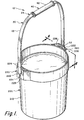
- the handle and container combination 10 preferably includes handle 20 and container 200.
- Handle 20 preferably includes a strap or bail 22 and a gripping means 40, such as sleeve member 42, positioned thereon.
- Container 200 preferably constitutes a bucket 210, but as will be apparent to one of ordinary skill in the art, container 200 can embody a wide variety of objects to which the handle might beneficially be attached. Examples include, without limitation, pails, boxes, etc., whether round, square, rectangular, oval. cubic or other configuration.
- Handle 20 is preferably configured to have bail or strap member 22 pivotably mounted on bucket 210, with a portion of strap member 22 configured to cooperatively engage handgrip 40.
- handgrip 40 preferably provides a convenient gripping surface for lifting or manipulating the assembly.
- Strap 22 and sleeve member 42 are preferably injection molded from plastic, but one of ordinary skill in the art will appreciate that either or both members may be manufactured with other suitable materials or methods. Desirable characteristics in these components include providing a flexible strap that can retain its shape, and a handgrip that provides increased comfort to the user.
- both strap 22 and sleeve 42 are preferably bi-directional (e.g. they can be assembled with respect to each other and with respect to the bucket in either direction), although unidirectional or other non-bi-directional embodiments can be provided and used.
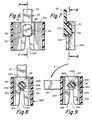
- the assembly of handle 20 and bucket 210 is preferably accomplished by engaging a clip member 50 (see FIG. 2) located near one of the ends of bail 22 with an opening such as a "bail ear" 228 (see FIGS. 8 and 9) on bucket 210.
- opening 228 includes a channel portion 224 that tapers from a mouth area 225 to a preferably generally semicircular seating portion 229.
- clip element 50 engages with opening 228 by sliding a relatively narrow stem portion 54 (see FIGS. 2 and 5) of clip means 50 through the mouth 225 of slot 224 to the seating portion 229 in hole 228.
- bucket or container 210 includes two openings (one each on opposing sidewalls of the bucket) to permit the attachment of the handle 20 to both sides of the bucket.
- two openings one each on opposing sidewalls of the bucket
- the preferred engagement could be provided on one end of the strap 22 and some other engagement mechanism on the other end.
- opening 228 is formed in a bail ear or other clip-receiving element 220 that includes a wall member 222 generally parallel to the sidewall of container 200 and spaced radially outwardly therefrom. Wall member 222 is preferably secured to container 200 by supporting structures 226.
- preferred clip member 50 can readily engage with bucket 210 without having to provide an opening within the actual sidewall of the bucket itself, thereby retaining sealing and structural integrity within the bucket itself.
- the bail or strap could be attached to the bucket or other object in a variety of other configurations, such as by providing an opening similar to opening 228 directly in the wall of the bucket or object (not shown). Persons of ordinary skill in the art will understand that certain aspects of the invention can be practiced with any pivotable connection between the handle and container.
- clip element 50 includes a relatively more narrow “stem” portion 54 and a wider head portion 52. It is sometimes convenient to refer to the narrow portion 54 of clip element 50 as a “stem” or a “neck”, and the wide portion 52 of clip 50 as a "clip head”.
- stem portion 54 acts as an axle rotatable within seating portion 229 of hole 228 in the side of bucket 210.
- Clip head portion 52 helps maintain the preferred rotatable engagement between handle 20 and bucket 210, by interferingly engaging with the parallel wall member 222 upon application of lifting force on handle 20.
- the side edges of clip head 52 can be “trimmed” (such as to form the relatively straight edges 62 and 63, FIGS. 2 and 6) or otherwise formed or configured in "non-round" shapes.
- such non-round configurations may be necessary to facilitate the passage of the preferred sleeve 42 onto the strap 22, for embodiments in which such a sleeve is used, as discussed elsewhere herein.
- an "untrimmed" clip head 52 could prevent assembly of the sleeve onto the strap.
- Trimming or otherwise altering the sides of the clip head 52 can address the problem, while still maintaining good engagement between the strap and the bucket (see FIG. 6).
- the "untrimmed" portions 60 of the clip head 52 extend further from the handle 20's axis of rotation and are normally aligned to effectively engage the wall member 222 and prevent the clip head 52 from being pulled out of engagement from the container 200 upon the application of lifting or similar force on the handle 20.
- FIGS. 6 and 7 illustrate the placement of clip element 50 in hole 228 after being slid through slot 224.
- FIG. 7 shows the placement of clip head 52 of clip element 50 against the inner side of the wall member 222.
- the engagement of clip 50 with hole 228 secures clip 50 to bucket 210 by the positioning of clip head 52 around hole 228.
- the entire underside or interior side of clip head 52 is preferably positioned to engage with wall member 222 (excepting at any gap, such as slot 224 in wall 222). The wider clip head thus prevents disengagement of the clip, and the handle, from the bucket.
- the "stem" or neck portion 54 is preferably generally elliptical in cross section. Among other things, this enables the strap to be inserted through mouth portion 225 of slot 224 (by aligning the narrow axis of the ellipse shape to make the stem “thin” so it can pass through the tapering slot) and thereafter pivotably retained in seating portion 229 of bail ear 228 on the side of the bucket (such as by, among other things, rotating the strap sideways to "misalign" the narrow ellipse axis and effectively “widen” the neck so it does not readily fall back down the slot 224).
- the "narrow" axis of the stem normally will only be “aligned” with slot 224 when bucket 210 is being carried. That very act of carrying will in most circumstances prevent the downward disengagement of the neck 54 out of slot 224 because the "carrying" will involve a lifting force on the handle 20 in the opposite direction. In effect, during those "carrying" periods, the lifting force exerted on the handle 20 will tend to keep the stem 54 from falling downwardly out of the slot 224. In other words, when bucket 210 is being carried, strap 22 will not normally "fall” out of engagement because, by definition, the user will be lifting the strap “up”, and thereby pulling stems 54 of clip elements 50 of strap 22 away from slot 224. Furthermore, the narrow portion 54 of clip element 50 is shaped to provide greater strength to the clip element in the direction of load, whether the container is being carried, poured from, or otherwise experiencing a load on the handle.
- the preferred slot 224 tapers to a slightly narrower width at its narrowest location 227, FIGS. 7-9, so that sliding the neck 54 through location 227 is an interference fit.
- the edges of slot 224 forming that narrowest location 227 preferably elastically deform slightly to permit the passage of the neck 54 therethrough, and preferably spring back to their approximately original position to help retain neck 54 from falling out of seating portion 229.
- the materials and dimensions of the member defining the slot 224 affect the amount of force required to insert the neck 54, the memory (or "return") the edges have after the neck 54 is inserted, and the difficulty of disengaging the neck once engaged.
- strap 22 will normally be rotated sideways in some degree (see FIG. 9, illustrating a 90 degree rotation) so that the "wider" stem axis of the elliptical neck 54 helps keep the strap 22 from disengaging from bucket 210.
- pouring from bucket 210 is more "secure” than with prior art circular necks because the widened elliptical neck is less likely to pull out of engagement.
- typical pouring may involve holding the bottom of bucket 210 with one hand while holding handle 20 with the other.
- Such pouring (or scooping material into the bucket, as discussed elsewhere herein) may be facilitated by rotating the handle 22 about an axis of clip element 50 (in FIG. 9, the axis may be viewed as an imaginary line perpendicular to the page through the center of element 54), as indicated by arrow A in FIG. 9.
- the handle 22 preferably can be moved through a "normal" full range of movement (from upright to "down” against the side of the container 200).
- the handle can be temporarily ''retained'' or otherwise positioned at any number of degrees through arc A, by engaging positioning means such as mateable elements 56 and 230 positioned around stem 54 and around the perimeter of opening 228, respectively.
- positioning means such as mateable elements 56 and 230 positioned around stem 54 and around the perimeter of opening 228, respectively.
- mateable elements 56 and 230 may be affected by a range of factors. including the nature of the materials from which handle 22 and bucket 210 are molded, the application for which the assembly is intended, and others.
- the various dimensions and materials from which the apparatus is fabricated can affect the strength of the "engagement" between the handle and the container, and correspondingly the amount of effort required for a user to move the handle from one such position to another.
- the elliptical stem in this "rotated" position preferably positions the widest elliptical dimension of neck 54 against slot 224, thereby reducing the risk of stem 54 pulling back through (out of) slot 224.
- the maximum benefit in this regard occurs when the handle 22 is positioned as shown in FIG. 9.
- prior art "circular neck” clips typically present a constant cross-section against the slot, regardless of the handle orientation. This cross-section is typically equal to the narrower of the two diameters of the elliptical stem as illustrated in the present application.
- the prior art effective neck stem dimension that is small enough to permit the circular stem to be engaged with the container does not "increase" as the handle is rotated from the vertical.
- positioning means such as one or more rib elements 56 are preferably provided on the sides of neck 54, and are sized, located, and shaped to permit selectable, frictional engagement with mating grooves 230 provided in hole 228 of bucket 210.
- Ribs 56, of neck 54 can retainingly engage with grooves 230 to temporarily position handle 20 at a desired rotated position with respect to bucket 210.
- rib or ribs 56 and grooves 230 are formed from a sufficiently deformable, resilient material to permit the movement of ribs 56 into and out of engagement from groove or grooves 230 with the application of some reasonable amount of force by a user.
- the preferred elliptical shape of neck 54 permits, among other things, the insertion of clip element 50 into hole 228 and the subsequent engagement of ribs 56 with grooves 230.
- rib or ribs 56 are positioned on neck 54 at locations off of the "narrow" elliptical axis so as to, among other things, not interfere with snapping neck 54 through the narrowest location 227 of slot 224.
- ribs 56 on stem 54 are preferably located on opposite sides of the longitudinal axis of the elliptical stem 54 (as best shown in FIG. 8).
- any number of ribs or grooves can be provided at any convenient position (such as out of alignment with each other or with the axis of the stem 54) to provide a desired range of movement and securement.
- stem 54 can still provide increased strength across the longitudinal axis of the elliptical cross-section of the stem and resistance to disengagement at various handle positions, as compared to prior art stems having a circular cross-section.
- ribs 56 and grooves 230 constitute mateable elements to permit, among other things, a user to position and temporarily "retain” the strap in various selected positions with respect to bucket 210.
- this aspect of the invention is the ability to position the strap out of the way when filling, or printing on, the bucket, without the use of external machinery or equipment.
- the preferred bucket and strap assembly incorporates within its own structure the ability to desirably position and temporarily retain the strap at a selected location (rather than simply hanging down against the side of the bucket, in the way of imprinting or other actions).
- the frictional engagement of ribs 56 and grooves 230 preferably permits, among other things, an end user to position and keep the handle in a vertical or nearly vertical position when the container is not being carried or used.
- this provides an additional ergonomic benefit to the end user by eliminating or reducing the amount of bend the user must employ in order to grasp the handle. For example, if the container and handle assembly is left with the handle so engaged vertically, a person can pick up or otherwise manipulate the container via the handle, without having to stoop as far down to reach the bail as would be required with conventional handle arrangements.
- prior art containers and handles typically require the use of additional machinery to temporarily move and retain handles away from the container to permit printing thereon.
- the preferred embodiment of the instant invention eliminates the need for manufacturers, suppliers, or other users to invest in the additional cost and space for such machinery, by providing means within the handle and bucket assembly itself to temporarily retain the strap at a selected position (such as during imprinting on the outside of the bucket).
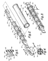
- FIGS. 2-4 provide further details regarding a preferred embodiment of the central portion 23 of strap member 22.
- preferred central portion 23 includes one or more engagement sites 30 for positioning sleeve 42 along the length of strap 22.
- sleeve 42 it will be desirable to have sleeve 42 at least generally centered between the ends of strap 22.
- Persons of ordinary skill in the art will understand, however, that various aspects of the invention can be practiced with the sleeve 42 positioned other than at the center of strap 22.
- various aspects of the invention can be practiced without any "positioning" at all of sleeve 42 along the length of strap 22. Such positioning can, however, retain the sleeve 42 at a generally optimal location for lifting or other manipulation of the container assembly, as discussed herein.
- the desired positioning of sleeve 42 in that regard is preferably accomplished by providing an engagement site 30 along the length of the strap, including one or more recessed channels 36, which can be conveniently bounded by two circular discs 34 formed on strap 22.
- engagement structures (such as elements 36 and 44) acting between the sleeve and the strap can be located at any number of engagement sites (or at multiple sites) along the length of sleeve 42 or strap 22 (respectively), depending on the particular application and the user's needs.
- a channel 36 is provided at the center of engagement site 30 acting to engagingly receive internal annular bead 44 on the interior of sleeve 42 (as best illustrated in FIG. 3).
- the internal annular bead 44 can be provided in many alternative embodiments (not shown), including, for example, one or more detents formed on the interior of sleeve 42.
- channel 36 and bead 44 on sleeve 42 permits generally free rotation of sleeve 42 around strap 22. Among other things, this enhances comfort during use because there is no sliding friction or related pull on a user's hand. Instead, the gripping surface provided by sleeve 42 preferably rotates upon the application of transverse force, eliminating sliding between the user's hand and sleeve 42.
- the central portion 23 of strap 22 further includes load-distributing structures 33 such as generally longitudinal elements 32 along the longitudinal axis of strap member 22 and one or more spaced circular discs 34 (preferably formed orthogonally to the longitudinal strap axis.
- the supporting structures 33 provide a number of benefits, including helping to distribute the bucket's weight across the sleeve 42 when lifting the bucket 210.
- the preferred embodiment includes four longitudinal elements 32 and six circular discs 34, but in alternative embodiments, any number of longitudinal elements or circular discs (or other supporting structures providing load-bearing contact between the sleeve 42 and strap 22) could be provided.
- FIG. 2 also illustrates a preferred embodiment of rotatable sleeve member 42 prior to its assembly onto strap 22.
- sleeve member 42 is cylindrical in shape, but as one of ordinary skill in the art can appreciate, the exterior gripping surface can embody a variety of shapes such as ovular, ribbed, or even more complex shapes to fit the contours of the users hand or fingers.
- FIG. 3 shows further details regarding the preferred rotatable sleeve 42 and its preferred assembly onto strap 22.
- FIG. 3 is a partial-sectional view of the sleeve member 42 operatively engaged with strap 22.
- Sleeve 42 is preferably configured with detent means 44 centrally located on an interior surface of sleeve 42, with detent 44 defining a continuous annulus that circumscribes that interior (as indicated above, detent 44 can be provided in a wide variety of alternative embodiments, including without limitation a plurality of such interior annular rings 44 spaced from each other inside sleeve 42).
- the preferred sleeve's interior ring 44 engages the strap's complementary recessed channel or locator ring portion 36 described above. In alternative embodiments (not shown), multiple interior annular rings 44 might engage multiple corresponding recessed channels or locator ring portions 36.
- detent 44 preferably is a continuous ring-like structure, it can be sectioned (e.g. quarters or eighths or otherwise, even randomly) and still permit the engagement of the sleeve with recessed ring 36 of the engagement site.
- the engagement structures can be located at any number of sites (or at multiple sites) along the length of sleeve 42 or strap 22 (respectively), depending on the particular application and the user's needs.
- both the strap and sleeve are made of plastic, but they can be made of any suitable material.
- FIGS. 2 and 5 illustrate the preferred embodiment of protruding clip element 50 at each end of strap 22.
- the particular size and shape of clip 50 will normally be selected and determined based on a number of factors. To provide a secure engagement with the bucket, clip 50 should be relatively large (e.g. the greater the anticipated load on the strap, the larger the clip probably needs to be).
- sleeve 42 preferably slides over the end of strap 22 to be assembled onto the center of the strap, however, the relative size of clip 50, sleeve 42, and other elements of the strap (e.g. circular discs 34 and longitudinal ribs 32) must be coordinated to provide both adequate load capacity (to provide sufficient strength and engagement of the handle 20 with the container 200 so that the anticipated load on the strap does not pull the strap out of engagement from the bucket) and permit ready assembly of the sleeve 42 onto the strap 22.
- One of the many approaches that can be taken (and may be necessary) in that regard is the aforementioned "trimming" of the clip head 52. As indicated above, this can be readily accomplished by, among other things, forming flat surfaces 62 and 63 on opposing sides of the head 52.
Landscapes
- Engineering & Computer Science (AREA)
- Mechanical Engineering (AREA)
- Details Of Rigid Or Semi-Rigid Containers (AREA)
- Table Devices Or Equipment (AREA)
- Thermally Insulated Containers For Foods (AREA)
- Auxiliary Devices For And Details Of Packaging Control (AREA)
- Passenger Equipment (AREA)
- Medical Preparation Storing Or Oral Administration Devices (AREA)
Claims (38)
- Poignée (20) pour transporter un récipient (200), ladite poignée (20) englobant un moyen d'attache (50) à des fins d'engrènement de la poignée (20) avec le récipient (200), ledit moyen d'attache (50) englobant une portion étroite (54) et une portion large (52), ladite portion étroite (54) possédant une section transversale non circulaire pour conférer une résistance supérieure audit moyen d'attache (50) dans la direction de la charge s'exerçant perpendiculairement à la poignée (20).
- Poignée selon la revendication 1, dans laquelle ladite portion étroite (54) dudit moyen d'attache (50) possède une section transversale de forme elliptique.
- Poignée selon la revendication 1, dans laquelle la poignée (20) englobe un élément en forme de sangle (22) sur lequel est disposée au moins une structure (33) de distribution de la charge afin de distribuer les forces de charge entre ledit élément (22) en forme de sangle et un élément périphérique en forme de manchon généralement cylindrique (42), ledit moyen d'attache (50) possédant une tige (54) de forme elliptique sur laquelle est disposé au moins un élément en forme de nervure (56) pour procurer un positionnement sélectionnable dudit élément (22) en forme de sangle lorsque ledit élément (22) en forme de sangle vient s'engrener avec un récipient (200).
- Poignée selon la revendication 3, dans laquelle au moins une desdites structures (33) de distribution de la charge vient s'engrener avec un ou plusieurs bourrelets (44) disposés sur la surface interne (40) dudit élément en forme de manchon généralement cylindrique (42).
- Poignée selon la revendication 3 ou 4, dans laquelle ledit moyen d'attache (50) est formé sur l'élément (22) en forme de sangle.
- Poignée selon la revendication 4, dans laquelle ledit élément (42) en forme de manchon est retenu sur la longueur de l'élément (22) en forme de sangle par des moyens d'encliquetage (44) disposés sur la surface interne dudit élément (42) en forme de manchon.
- Poignée selon la revendication 6, dans laquelle ledit élément (42) en forme de manchon à l'état retenu est à même d'effectuer des rotations autour dudit élément (22) en forme de sangle.
- Poignée selon la revendication 1, dans laquelle ledit moyen d'attache (50) est formé en permanence sur et en une seule pièce avec un élément allongé (20) en forme de sangle de poignée de récipient, et ladite portion étroite (54) du moyen d'attache est située entre ladite portion large (52) et ledit élément (20) en forme de sangle, au moins un élément (56) en forme de nervure étant disposé sur ladite portion étroite (54) pour procurer un positionnement sélectionnable de l'élément (20) en forme de sangle, lorsque ledit élément (20) en forme de sangle vient s'engrener avec un récipient (200).
- Poignée selon la revendication 8, dans laquelle ladite portion large est configurée pour permettre à un manchon rotatif (42) de coulisser par-dessus ladite portion à des fins d'assemblage sur la poignée de récipient (20) à un endroit espacé dudit moyen d'attache (50).
- Poignée selon la revendication 8 ou 9, dans laquelle ladite portion étroite (54) possède une section transversale de forme elliptique.
- Poignée selon la revendication 1, dans laquelle ladite poignée (20) englobe un étrier (22) en matière plastique et un élément (42) en forme de manchon en matière plastique qui englobe au moins une portion tubulaire monolithique (40) autour d'au moins une portion dudit étrier (22), ledit élément (42) en forme de manchon procurant une surface d'adhérence pour manipuler le récipient (200), dans lequel ledit étrier (22) possède une première extrémité et une deuxième extrémité, et ledit étrier (22) englobe ledit élément d'attache (50) en position adjacente à au moins une desdites extrémités à des fins d'engrènement avec le récipient (200).
- Poignée selon la revendication 11, dans laquelle ledit élément d'attache (50) possède une section transversale de forme elliptique.
- Poignée selon la revendication 11, dans laquelle ledit élément (42) en forme de manchon est monté en rotation sur ledit étrier (22), et englobe en outre des structures correspondantes d'engrènement (30, 44) sur ledit étrier (22) et sur ledit élément (42) en forme de manchon dans le but de retenir ledit élément (42) en forme de manchon à une position sélectionnée sur l'axe longitudinal dudit étrier (22).
- Poignée selon la revendication 11, dans laquelle ledit étrier (22) englobe plusieurs structures (32, 34) pour transmettre des forces de charge entre ledit étrier (22) et ledit élément (42) en forme de manchon.
- Poignée selon la revendication 11 ou 12, dans laquelle un moyen de positionnement (56) est disposé par-dessus ledit élément d'attache (50) pour positionner et engrener ladite poignée (20) dans une position sélectionnée par rapport au récipient (200).
- Poignée selon la revendication 15, dans laquelle ledit moyen de positionnement (56) permet de positionner ladite poignée (20) et de la maintenir dans une position essentiellement verticale lorsque le récipient (200) se trouve dans sa position de dressée normale et n'est pas porté ou utilisé.
- Poignée selon la revendication 11, dans laquelle ledit élément (42) en forme de manchon est réalisé sous la forme d'une structure unitaire.
- Poignée selon la revendication 11, dans laquelle lesdites structures d'engrènement correspondantes (34, 44) englobent une structure de bourrelet (44) et une rainure annulaire (36), ladite structure de bourrelet (44) étant configurée pour venir se disposer à l'intérieur de ladite rainure annulaire (36).
- Poignée selon la revendication 11, dans laquelle ledit étrier (22) englobe un élément (22) allongé en forme de sangle possédant des portions relativement flexibles à ses extrémités et une portion (23) relativement rigide entre ses extrémités, ledit élément de manchon (42) de forme généralement cylindrique étant configuré pour recouvrir au moins une partie de ladite portion (23) relativement rigide dudit élément (22) en forme de sangle, ledit élément (42) en forme de manchon étant également apte à effectuer des rotations autour de l'axe longitudinal de ladite portion relativement rigide (23) dudit élément (22) en forme de sangle.
- Poignée selon la revendication 19, englobant en outre des éléments coopérants (32, 34, 44) sur ledit élément (22) en forme de sangle et sur ledit élément (42) en forme de manchon pour empêcher un mouvement axial par inadvertance dudit élément (42) en forme de manchon le long dudit axe longitudinal dudit élément (22) en forme de sangle.
- Poignée selon la revendication 19, dans laquelle lesdites portions relativement flexibles dudit élément (22) en forme de sangle possèdent une section transversale généralement rectangulaire, ledit élément (42) en forme de manchon englobe une surface intérieure (40) qui est généralement de forme arrondie, et ladite portion (23) relativement rigide dudit élément (22) en forme de sangle englobe au moins une surface d'appui (34) s'étendant au-delà de la configuration de ladite section transversale généralement rectangulaire, ladite surface d'appui (34) étant configurée pour épouser en rotation au moins une portion de ladite surface intérieure (40) dudit élément (42) en forme de manchon.
- Poignée selon la revendication 21, dans laquelle dans laquelle ladite portion rigide (23) englobe plusieurs disques généralement circulaires (34) qui sont généralement perpendiculaires audit axe longitudinal dudit élément (22) en forme de sangle, lesdits disques (34) étant dimensionnés et configurés pour venir s'insérer à l'intérieur dudit élément (42) en forme de manchon lorsque ledit élément (42) en forme de manchon est positionné autour de ladite portion, ladite au moins une surface d'appui englobant au moins un desdits disques (34).
- Poignée selon la revendication 22, dans laquelle ladite portion rigide (23) englobe des nervures de rigidification (32) entre lesdits plusieurs disques (34), lesdites nervures de rigidification (32) étant généralement parallèles audit axe longitudinal dudit élément (22) en forme de sangle.
- Poignée selon la revendication 11, dans laquelle ledit étrier (22) représente une sangle (22) généralement flexible coopérant avec ledit manchon (42), ladite sangle (22) englobant des structures d'engrènement (52, 54) à ses extrémités à des fins d'engrènement de ladite sangle (22) avec le récipient (200), ladite sangle (22) étant configurée de telle sorte qu'au moins approximativement la moitié de ladite sangle (22), sur laquelle sont disposées lesdites structures d'engrènement (52, 54), est à même de traverser ledit manchon (42), ledit manchon (42) pouvant de cette manière venir se positionner approximativement à mi-distance le long de ladite sangle (22), ledit manchon (42) étant à même d'effectuer des rotations sur ladite sangle (22) lorsqu'il est positionné de cette manière le long de ladite sangle (22).
- Poignée selon la revendication 24, englobant en outre des éléments coopérants (34, 44) sur ladite sangle (22) et sur ledit manchon (42) afin de maintenir ledit manchon (42) dans ladite position approximativement à mi-distance le long de ladite sangle (22).
- Combinaison d'une poignée (20) selon la revendication 11 et d'un récipient (200), dans laquelle ledit élément d'attache (50) en position adjacente à au moins une des extrémités dudit étrier vient s'engrener avec ledit récipient (200), ledit élément d'attache (50) possédant une section transversale de forme elliptique.
- Combinaison d'une poignée (20) selon la revendication 11 et d'un récipient (200), dans laquelle ladite poignée (20) englobe un élément (22) en forme de sangle comprenant une section allongée sur laquelle est disposée au moins une structure (33) de distribution de la charge pour distribuer les forces de charge entre ledit élément (22) en forme de sangle et l'élément périphérique (42) en forme de manchon généralement cylindrique, ledit moyen d'attache (50) formé sur ledit élément (22) en forme de sangle comportant une tige (54) de forme elliptique sur laquelle est disposé au moins un élément en forme de nervure (56) pour procurer un positionnement sélectionnable dudit élément (22) en forme de sangle lorsque ledit élément en forme de sangle vient s'engrener avec ledit récipient (200).
- Combinaison d'une poignée (20) selon la revendication 1 et d'un récipient, dans laquelle ledit moyen d'attache (50) est disposé sur un élément allongé (22) en forme de sangle de poignée de récipient et ladite portion étroite (54) est située entre ladite portion large (52) et ledit élément (22) en forme de sangle, au moins un élément (56) en forme de nervure étant disposé sur ladite portion étroite (54) dans le but de procurer un positionnement sélectionnable de la poignée (20) par rapport audit récipient (200) avec lequel elle vient s'engrener.
- Combinaison d'une poignée (20) selon la revendication 1 et d'un récipient (200), dans laquelle ladite poignée (20) vient s'engrener avec ledit récipient (200) , ladite portion étroite (54) de l'attache possède une section transversale de forme elliptique pour conférer une résistance supérieure audit élément d'attache (50) dans la direction de la charge s'exerçant perpendiculairement à la poignée (20).
- Combinaison d'une poignée (20) selon la revendication 1 et d'un récipient (200), dans laquelle la poignée (20) englobe un élément en forme de sangle (22) sur lequel est disposée au moins une structure (33) de distribution de la charge afin de distribuer les forces de charge entre ledit élément (22) en forme de sangle et un élément périphérique en forme de manchon généralement cylindrique (42), ledit moyen d'attache (50) possédant une tige (54) de forme elliptique sur laquelle est disposé au moins un élément en forme de nervure (56) pour procurer un positionnement sélectionnable dudit élément (22) en forme de sangle lorsque ledit élément (22) en forme de sangle vient s'engrener avec ledit récipient (200).
- Combinaison d'une poignée selon la revendication 11 et d'un récipient (200), dans laquelle ledit élément (42) en matière plastique en forme de manchon est disposé en rotation autour de la portion centrale (23) dudit étrier (22), ledit étrier (22) en matière plastique possédant au moins une portion terminale généralement flexible pour permettre un montage sélectif dudit élément (42) en forme de manchon sur ledit étrier (22) et un retrait dudit élément (42) en forme de manchon par rapport audit étrier (22), pour ainsi obtenir un assemblage opérationnel avec ledit récipient (200) .
- Procédé de connexion d'une poignée (20) à un récipient (200), englobant les étapes consistant à :a) procurer une sangle allongée (22) possédant un élément d'attache (50), une portion (54) de ce dernier en forme de tige possédant une section transversale de forme elliptique ;b) disposer ladite portion (54) en forme de tige en position adjacente à une fente (224) formée sur ledit récipient (200) de telle sorte que le petit axe de ladite section transversale de configuration elliptique est généralement perpendiculaire à l'axe longitudinal de ladite fente (224) ;c) faire glisser ladite portion (54) en forme de tige à travers une portion étroite de ladite fente (224) tandis que lesdits axes sont généralement perpendiculaires l'un à l'autre, pour la faire passer dans une portion large de ladite fente (224) ; etd) faire tourner ladite portion (54) en forme de tige de telle sorte que ledit petit axe de ladite section transversale de configuration elliptique ne se trouve plus en alignement généralement perpendiculaire avec ledit axe longitudinal de ladite fente (224).
- Procédé selon la revendication 32, englobant en outre les étapes consistant à procurer au moins une paire d'éléments d'engrènement coopérants (56, 230) sur ladite portion (54) en forme de tige et sur ladite portion plus large de ladite fente (224) et fixer de manière temporaire ladite poignée (20) en antirotation autour de la portion (54) en forme de tige par engrènement desdits éléments d'engrènement coopérants (56, 230).
- Procédé selon la revendication 32 ou 33, englobant les étapes consistant à :monter un élément (42) en forme de manchon cylindrique sur ladite sangle allongée (22) ;faire en sorte que ledit élément (42) en forme de manchon cylindrique vienne s'engrener avec ladite sangle (22) sur la longueur de cette dernière via l'engrènement d'un bourrelet de positionnement (44) sur la surface interne (40) dudit élément (42) en forme de manchon avec un site d'engrènement (34, 36) sur ladite sangle (22).
- Procédé selon la revendication 33, englobant en outre l'étape consistant à imprimer des informations sur ledit récipient (200) tandis que ladite poignée (20) est fixée temporairement de cette manière.
- Procédé selon la revendication 32 ou 33, dans lequel lesdites étapes sont automatisées.
- Procédé selon la revendication 32, englobant en outre les étapes consistant àa) faire glisser un élément (42) en matière plastique en forme de manchon par-dessus l'élément (22) allongé en matière plastique en forme de sangle ; etb) faire en sorte qu'un bourrelet de positionnement (44) sur la surface interne dudit élément (42) en forme de manchon vienne s'engrener avec un site d'engrènement (34, 36) dudit élément (22) en forme de sangle.
- Procédé selon la revendication 32, dans lequel ladite poignée (20) englobe un élément allongé (22) en forme de sangle possédant des portions relativement flexibles à ses extrémités et une portion relativement rigide (23) entre ses extrémités, ainsi qu'un élément (42) en forme de manchon généralement cylindrique configuré pour recouvrir au moins une partie de ladite portion relativement rigide (23) dudit élément (22) en forme de sangle, ledit procédé englobant les étapes consistant à insérer une desdites portions relativement flexibles dudit élément (22) en forme de sangle à travers ledit élément (42) en forme de manchon, à faire glisser ledit élément (22) en forme de manchon en position par-dessus ladite portion relativement rigide (23) dudit élément (22) en forme de sangle, à fléchir au moins une desdites portions relativement flexibles dudit élément (22) en forme de sangle afin de disposer l'extrémité dudit élément en position adjacente audit récipient (200), et à faire en sorte que ladite extrémité vienne s'engrener avec la structure coopérante (220) sur ledit récipient (200).
Priority Applications (2)
| Application Number | Priority Date | Filing Date | Title |
|---|---|---|---|
| EP03075493A EP1323638A3 (fr) | 1999-04-08 | 2000-03-31 | Poignée de récipient et procédés associés |
| EP10181787.2A EP2263946A3 (fr) | 1999-04-08 | 2000-03-31 | Poignée de récipient et procédés associés |
Applications Claiming Priority (3)
| Application Number | Priority Date | Filing Date | Title |
|---|---|---|---|
| US288590 | 1999-04-08 | ||
| US09/288,590 US6257440B1 (en) | 1999-04-08 | 1999-04-08 | Container handle and related methods |
| PCT/US2000/008632 WO2000061446A1 (fr) | 1999-04-08 | 2000-03-31 | Poignee de recipient et procedes associes |
Related Child Applications (1)
| Application Number | Title | Priority Date | Filing Date |
|---|---|---|---|
| EP03075493A Division EP1323638A3 (fr) | 1999-04-08 | 2000-03-31 | Poignée de récipient et procédés associés |
Publications (2)
| Publication Number | Publication Date |
|---|---|
| EP1165387A1 EP1165387A1 (fr) | 2002-01-02 |
| EP1165387B1 true EP1165387B1 (fr) | 2004-06-09 |
Family
ID=23107774
Family Applications (3)
| Application Number | Title | Priority Date | Filing Date |
|---|---|---|---|
| EP03075493A Withdrawn EP1323638A3 (fr) | 1999-04-08 | 2000-03-31 | Poignée de récipient et procédés associés |
| EP00918521A Expired - Lifetime EP1165387B1 (fr) | 1999-04-08 | 2000-03-31 | Poignee de recipient et procedes associes |
| EP10181787.2A Withdrawn EP2263946A3 (fr) | 1999-04-08 | 2000-03-31 | Poignée de récipient et procédés associés |
Family Applications Before (1)
| Application Number | Title | Priority Date | Filing Date |
|---|---|---|---|
| EP03075493A Withdrawn EP1323638A3 (fr) | 1999-04-08 | 2000-03-31 | Poignée de récipient et procédés associés |
Family Applications After (1)
| Application Number | Title | Priority Date | Filing Date |
|---|---|---|---|
| EP10181787.2A Withdrawn EP2263946A3 (fr) | 1999-04-08 | 2000-03-31 | Poignée de récipient et procédés associés |
Country Status (15)
| Country | Link |
|---|---|
| US (2) | US6257440B1 (fr) |
| EP (3) | EP1323638A3 (fr) |
| JP (1) | JP4427193B2 (fr) |
| AT (1) | ATE268721T1 (fr) |
| AU (1) | AU778912B2 (fr) |
| BR (1) | BR0009600B1 (fr) |
| CA (1) | CA2369686C (fr) |
| DE (1) | DE60011410T2 (fr) |
| DK (1) | DK1165387T3 (fr) |
| MX (1) | MXPA01010219A (fr) |
| MY (1) | MY141311A (fr) |
| NZ (2) | NZ515151A (fr) |
| TW (1) | TW570889B (fr) |
| WO (1) | WO2000061446A1 (fr) |
| ZA (1) | ZA200108225B (fr) |
Families Citing this family (67)
| Publication number | Priority date | Publication date | Assignee | Title |
|---|---|---|---|---|
| US6257440B1 (en) * | 1999-04-08 | 2001-07-10 | Ropak Corporation | Container handle and related methods |
| CN1646046A (zh) * | 2002-04-19 | 2005-07-27 | 里克公司 | 用于容纳产品的改进型容器 |
| US6997354B2 (en) * | 2002-07-19 | 2006-02-14 | Rieke Corporation | Sealing mechanisms for use in liquid-storage containers |
| US7347343B2 (en) * | 2002-07-19 | 2008-03-25 | Rieke Corporation | Container for liquids, including sealing mechanisms |
| US7040509B2 (en) * | 2002-07-19 | 2006-05-09 | Rieke Corporation | Container for liquids, including sealing mechanisms |
| US6843389B2 (en) * | 2002-07-19 | 2005-01-18 | Rieke Corporation | Sealing mechanisms for use in liquid-storage containers |
| US20060144841A1 (en) * | 2003-01-06 | 2006-07-06 | James Sener | Multi-purpose cooler |
| US6854617B2 (en) * | 2003-03-21 | 2005-02-15 | Rieke Corporation | Blow-molded paint container |
| DE10324826A1 (de) * | 2003-05-30 | 2004-12-16 | Hako-Werke Gmbh | Bodenreinigungsmaschine |
| CA2531841A1 (fr) * | 2003-07-09 | 2005-01-27 | Masterchem Industries, Llc | Poignee de receptacle de peinture |
| US6779680B1 (en) * | 2003-11-25 | 2004-08-24 | Letica Corporation | Molded plastic container with opposite exterior lifting elements with finger protection |
| ITFI20040069A1 (it) * | 2004-03-23 | 2004-06-23 | Tecnorama Srl | Cestello,macchina ed impianto per la tintura di materiali tessili |
| US20050241114A1 (en) * | 2004-04-30 | 2005-11-03 | North America Packaging Corporation | Pail handle |
| US7367476B2 (en) * | 2004-08-30 | 2008-05-06 | Rieke Corporation | Airless dispensing pump with tamper evidence features |
| US7654418B2 (en) * | 2004-08-30 | 2010-02-02 | Rieke Corporation | Airless dispensing pump |
| US8556115B2 (en) * | 2004-12-02 | 2013-10-15 | Symmetry Medical Manufacturing, Inc. | Surgical instrument container assembly with elliptical softgrip handle assembly |
| US7578411B1 (en) * | 2006-06-22 | 2009-08-25 | Miller Manufacturing Company, Inc. | Bucket bail grip |
| US8662015B2 (en) * | 2006-08-15 | 2014-03-04 | Droll Yankees, Inc. | Bird feeder |
| US20080099424A1 (en) * | 2006-10-30 | 2008-05-01 | Adam Chalekian | Apparatus and methods for carrying a bottle |
| US8047387B2 (en) * | 2006-10-30 | 2011-11-01 | Tote One, Llc | Apparatus and methods for carrying a bottle |
| US20080105584A1 (en) * | 2006-11-02 | 2008-05-08 | Garnett Jay Cecil | System, method and article of manufacture for separating stacked storage containers |
| US7938286B2 (en) | 2007-02-13 | 2011-05-10 | Gateway Plastics, Inc. | Container system |
| US20100004629A1 (en) * | 2008-07-03 | 2010-01-07 | Drip Drop Solutions, Inc. | Apparatus and methods to implement a versatile liquid storage and delivery mechanism |
| JP4623164B2 (ja) * | 2008-08-21 | 2011-02-02 | セイコーエプソン株式会社 | プロジェクタ |
| DE102009007730B4 (de) | 2009-02-05 | 2017-12-14 | Mbda Deutschland Gmbh | Strukturbauteil |
| US8459486B2 (en) | 2010-04-19 | 2013-06-11 | Ropak Corporation | Container and lid |
| JP2011018061A (ja) * | 2010-08-19 | 2011-01-27 | Seiko Epson Corp | プロジェクタ |
| US9555930B2 (en) * | 2011-08-30 | 2017-01-31 | Kw Container | Handle assembly for plastic container |
| US20120055583A1 (en) * | 2010-09-08 | 2012-03-08 | Schnatter John H | Sauce Leveler Device |
| US20120085774A1 (en) * | 2010-10-07 | 2012-04-12 | Ropak Corporation | One-piece container handle |
| CN103958216A (zh) * | 2011-08-30 | 2014-07-30 | Kw容器公司 | 用于塑料容器的手柄系统 |
| GB2495783B (en) * | 2011-10-21 | 2015-04-01 | Alison Bateman | Handle and Collar for Beverage Cups |
| CA2805214A1 (fr) * | 2012-02-10 | 2013-08-10 | Philip R. Short | Recipients avec cavites pour poignees encastrees |
| US8870007B2 (en) * | 2012-08-27 | 2014-10-28 | Edward S. Robbins, Iii | Cup holder with recessed movable handle |
| KR101463687B1 (ko) * | 2013-05-16 | 2014-11-19 | 김충구 | 캔용기 스트랩 |
| US9303353B2 (en) * | 2013-06-12 | 2016-04-05 | United Comb + Novelty Corporation | Basket |
| US9119491B2 (en) | 2013-09-12 | 2015-09-01 | Edward S. Robbins, III | Cup holder with more and less flexible portions and recessed movable handle |
| DE102014011898B4 (de) * | 2014-08-11 | 2017-01-05 | Tesfaye Asegu | Adaptive Eimerhenkel-Verlängerung für gesundes und mobiles Arbeiten mit Eimern; Adaptive Eimerhenkel-Verlängerung für gesundes und mobiles Arbeiten mit Eimern mit zwei weiteren Hakengiffen zum Aufhängen und Tragen |
| AU2015246064B2 (en) * | 2014-10-21 | 2020-07-02 | Arrow Plastics Pty Ltd | A container |
| USD759927S1 (en) | 2015-04-27 | 2016-06-21 | Ipl Inc. | Container handle |
| EP3088320B1 (fr) * | 2015-04-28 | 2018-02-28 | Siropack Italia S.r.l. | Récipient pour produits alimentaires et procédé pour sa fabrication |
| KR101642792B1 (ko) * | 2015-06-15 | 2016-08-17 | 주식회사 쓰리스타 | 휴대형 야외 취사팩 |
| USD782664S1 (en) * | 2015-09-14 | 2017-03-28 | Fresenius Medical Care Holdings, Inc. | Reusable carrying handle |
| US10472130B2 (en) * | 2015-12-03 | 2019-11-12 | Norman Foster | Bucket handle assembly |
| CN106927170B (zh) * | 2015-12-31 | 2022-07-08 | 珠海格力电器股份有限公司 | 垃圾桶 |
| US20170253415A1 (en) * | 2016-03-07 | 2017-09-07 | Joseph Scott Schneider | Insulating container |
| USD815786S1 (en) | 2017-02-27 | 2018-04-17 | Yeti Coolers, Llc | Bucket |
| USD816285S1 (en) | 2017-02-27 | 2018-04-24 | Yeti Coolers, Llc | Lid |
| USD815788S1 (en) | 2017-02-27 | 2018-04-17 | Yeti Coolers, Llc | Bucket |
| USD824674S1 (en) | 2017-02-27 | 2018-08-07 | Yeti Coolers, Llc | Tray |
| USD815787S1 (en) | 2017-02-27 | 2018-04-17 | Yeti Coolers, Llc | Bucket |
| US10597191B2 (en) | 2017-02-28 | 2020-03-24 | Yeti Coolers, Llc | Portable container and container assembly |
| USD819910S1 (en) | 2017-03-23 | 2018-06-05 | Yeti Coolers, Llc | Utility wrap |
| USD820542S1 (en) | 2017-03-23 | 2018-06-12 | Yeti Coolers, Llc | Utility wrap |
| USD818660S1 (en) | 2017-03-23 | 2018-05-22 | Yeti Coolers, Llc | Utility wrap |
| USD819288S1 (en) | 2017-03-23 | 2018-05-29 | Yeti Coolers, Llc | Utility wrap |
| USD817575S1 (en) | 2017-03-23 | 2018-05-08 | Yeti Coolers, Llc | Utility wrap |
| USD818661S1 (en) | 2017-03-23 | 2018-05-22 | Yeti Coolers, Llc | Utility wrap |
| JP6956374B2 (ja) * | 2017-05-30 | 2021-11-02 | パナソニックIpマネジメント株式会社 | バケツ |
| US10266307B1 (en) | 2018-04-12 | 2019-04-23 | Andax Industries Llc | Equipment bag with closure sleeve |
| CA3098319A1 (fr) * | 2018-05-10 | 2019-11-14 | Construction Research & Technology Gmbh | Seau |
| USD881495S1 (en) * | 2018-09-27 | 2020-04-14 | Ipl Inc. | Container |
| US20200353118A1 (en) * | 2019-05-10 | 2020-11-12 | Ecolab Usa Inc. | pH SENSITIVE COLOR INDICATOR FOR SANITIZING APPLICATIONS |
| US11358753B2 (en) | 2019-07-26 | 2022-06-14 | Andax Industries Llc | Equipment transfer bag |
| US11584566B2 (en) | 2020-08-07 | 2023-02-21 | Yeti Coolers, Llc | Portable container, container assembly, and accessories |
| US20230415960A1 (en) * | 2021-03-10 | 2023-12-28 | Chaitanya Matthew Falcher | Attachable handle system |
| US11981480B2 (en) * | 2022-10-06 | 2024-05-14 | Dart Industries Inc. | Serving dish cover |
Family Cites Families (40)
| Publication number | Priority date | Publication date | Assignee | Title |
|---|---|---|---|---|
| US308343A (en) | 1884-11-25 | Pail handle | ||
| US3128905A (en) | 1964-04-14 | Wire handle for a molded container | ||
| US472130A (en) | 1892-04-05 | Detachable bail and ear therefor | ||
| US1678005A (en) | 1925-06-12 | 1928-07-24 | Frank W A Hallerman | Bail handle |
| US2101869A (en) | 1934-11-27 | 1937-12-14 | Sullivan Machinery Co | Vibration reducing means |
| US2176711A (en) | 1937-02-18 | 1939-10-17 | Jr Thomas J Gorman | Means for attaching bails to cans |
| US2255633A (en) | 1939-08-28 | 1941-09-09 | Morris Lavine | Can carrier |
| US2654115A (en) * | 1951-04-10 | 1953-10-06 | Revce Inc | Snap-on basket handle |
| GB722573A (en) | 1952-10-24 | 1955-01-26 | British Xylonite Co Ltd | Improvements in or relating to buckets or like receptacles having hoop-like handles |
| GB1031092A (en) * | 1962-02-13 | 1966-05-25 | Harold Albert Hadleigh Crowthe | Improvements in or relating to baskets or the like |
| US3189069A (en) | 1963-12-06 | 1965-06-15 | Stanley Works | Tool handle with resilient gripping means |
| US3275366A (en) * | 1965-02-23 | 1966-09-27 | Walter E Hidding | Plastic carrier for bottles |
| US3586200A (en) * | 1968-11-01 | 1971-06-22 | Life Like Products Inc | Carrying handle |
| US3656594A (en) | 1970-08-27 | 1972-04-18 | Bruce Plastics Inc | Luggage handles |
| US3813004A (en) * | 1972-09-13 | 1974-05-28 | Weston Instruments Inc | Portable instrument |
| US4071939A (en) | 1972-12-11 | 1978-02-07 | Superfos Emgallage A/S | Method of mounting a handle on a pail |
| US4071063A (en) * | 1976-06-17 | 1978-01-31 | Swift & Company | Non-releasable hand grip for package or loop handle of a bag |
| AU526813B2 (en) * | 1978-02-24 | 1983-02-03 | Innovative Design Co. Pty. Ltd. | Method of connecting a bail to a container |
| US4177542A (en) | 1978-06-08 | 1979-12-11 | Vector Engineering Corporation | Handhold insert for a twisted rope |
| DK144239C (da) | 1978-08-24 | 1982-06-21 | Superfos Emballage As | Emballageboette |
| GB2095214B (en) * | 1981-03-20 | 1984-11-28 | Mothercare Ltd | A portable body with carrying handle |
| US4351449A (en) * | 1981-05-22 | 1982-09-28 | Zobel Dwight D | Self-locking, unlocking detachable hand lever cam sealed container |
| US4365725A (en) * | 1981-07-28 | 1982-12-28 | Dravo Corporation | Basket with swing away double locking handle |
| DE3138782A1 (de) * | 1981-09-30 | 1983-04-14 | Dieter H. 7928 Giengen Kaiser | Transportables gepaeckstueck, insbesondere koffer |
| NL174819B (nl) * | 1982-01-15 | 1984-03-16 | Curver Verpakkingen | Houder met in diverse standen te fixeren draagbeugel. |
| GB8323845D0 (en) | 1983-09-06 | 1983-10-05 | Superfos Packaging Uk Ltd | Handle for container |
| US4632357A (en) | 1984-12-12 | 1986-12-30 | Holdt J W Von | Mold for making a bucket with bail |
| US4841596A (en) | 1988-06-03 | 1989-06-27 | Nellie M. Fink | Handle with shaped recesses to support flimsy bag straps |
| US4890355A (en) * | 1988-10-26 | 1990-01-02 | Schulten Elizabeth W | Releasably mountable hand grip for handles |
| US5060998A (en) | 1989-08-21 | 1991-10-29 | Phillips Pamela S | Shopping aid |
| GB2244972A (en) | 1990-06-12 | 1991-12-18 | Lin Pac Mouldings | Container with pivotally mounted handle |
| US5199571A (en) * | 1991-03-22 | 1993-04-06 | Rubbermaid Incorporated | Nestable buckets having lockable bails |
| US5251781A (en) * | 1991-06-21 | 1993-10-12 | Skelton Christopher R | Method for steadily holding a container |
| US5145082A (en) | 1991-09-10 | 1992-09-08 | Craft Jr Charles W | Handle reinforcement mechanism for laundry basket |
| US5287990A (en) * | 1992-07-10 | 1994-02-22 | Cardinal Packaging, Inc. | Plastic bail handle |
| US5402910A (en) | 1993-02-12 | 1995-04-04 | Pilney; Craig | Container having ladder attachable handle |
| US5344041A (en) | 1993-09-14 | 1994-09-06 | Ropak Corporation | Bail for container and attachment means therefor |
| US5437369A (en) | 1993-12-01 | 1995-08-01 | Spitere; Thomas C. | Tool bucket with tool-locking handle |
| GB9503145D0 (en) * | 1995-02-17 | 1995-04-05 | Ind Containers Ltd | Container with handle |
| US6257440B1 (en) * | 1999-04-08 | 2001-07-10 | Ropak Corporation | Container handle and related methods |
-
1999
- 1999-04-08 US US09/288,590 patent/US6257440B1/en not_active Expired - Lifetime
- 1999-09-17 TW TW088116058A patent/TW570889B/zh not_active IP Right Cessation
-
2000
- 2000-03-31 MX MXPA01010219A patent/MXPA01010219A/es active IP Right Grant
- 2000-03-31 NZ NZ515151A patent/NZ515151A/en not_active IP Right Cessation
- 2000-03-31 JP JP2000610736A patent/JP4427193B2/ja not_active Expired - Fee Related
- 2000-03-31 BR BRPI0009600-8A patent/BR0009600B1/pt not_active IP Right Cessation
- 2000-03-31 AT AT00918521T patent/ATE268721T1/de active
- 2000-03-31 DE DE60011410T patent/DE60011410T2/de not_active Expired - Lifetime
- 2000-03-31 DK DK00918521T patent/DK1165387T3/da active
- 2000-03-31 EP EP03075493A patent/EP1323638A3/fr not_active Withdrawn
- 2000-03-31 EP EP00918521A patent/EP1165387B1/fr not_active Expired - Lifetime
- 2000-03-31 WO PCT/US2000/008632 patent/WO2000061446A1/fr active IP Right Grant
- 2000-03-31 NZ NZ528842A patent/NZ528842A/en not_active IP Right Cessation
- 2000-03-31 CA CA002369686A patent/CA2369686C/fr not_active Expired - Lifetime
- 2000-03-31 AU AU39319/00A patent/AU778912B2/en not_active Ceased
- 2000-03-31 EP EP10181787.2A patent/EP2263946A3/fr not_active Withdrawn
- 2000-04-05 MY MYPI20001412A patent/MY141311A/en unknown
-
2001
- 2001-06-05 US US09/875,709 patent/US6494341B2/en not_active Expired - Lifetime
- 2001-10-05 ZA ZA200108225A patent/ZA200108225B/xx unknown
Also Published As
| Publication number | Publication date |
|---|---|
| ATE268721T1 (de) | 2004-06-15 |
| MY141311A (en) | 2010-04-16 |
| JP4427193B2 (ja) | 2010-03-03 |
| DE60011410D1 (de) | 2004-07-15 |
| TW570889B (en) | 2004-01-11 |
| BR0009600A (pt) | 2002-01-08 |
| EP1323638A2 (fr) | 2003-07-02 |
| EP2263946A2 (fr) | 2010-12-22 |
| DK1165387T3 (da) | 2004-08-30 |
| JP2002541032A (ja) | 2002-12-03 |
| NZ515151A (en) | 2004-04-30 |
| AU3931900A (en) | 2000-11-14 |
| US6494341B2 (en) | 2002-12-17 |
| CA2369686C (fr) | 2009-06-09 |
| BR0009600B1 (pt) | 2011-01-25 |
| EP2263946A3 (fr) | 2013-06-05 |
| WO2000061446B1 (fr) | 2001-01-25 |
| EP1165387A1 (fr) | 2002-01-02 |
| EP1323638A3 (fr) | 2011-08-03 |
| MXPA01010219A (es) | 2003-07-21 |
| DE60011410T2 (de) | 2005-06-16 |
| ZA200108225B (en) | 2003-10-29 |
| CA2369686A1 (fr) | 2000-10-19 |
| WO2000061446A1 (fr) | 2000-10-19 |
| NZ528842A (en) | 2005-07-29 |
| AU778912B2 (en) | 2004-12-23 |
| WO2000061446A8 (fr) | 2001-05-03 |
| US6257440B1 (en) | 2001-07-10 |
| US20010027980A1 (en) | 2001-10-11 |
Similar Documents
| Publication | Publication Date | Title |
|---|---|---|
| EP1165387B1 (fr) | Poignee de recipient et procedes associes | |
| US20120085774A1 (en) | One-piece container handle | |
| US5183169A (en) | Reusable bottle handle | |
| US7805813B1 (en) | Grip for use on a bail | |
| US9914560B2 (en) | Bucket handle | |
| US8448812B2 (en) | Waste container with base member | |
| US5658044A (en) | Infant carrier handle | |
| JP2002541032A5 (fr) | ||
| US6405409B1 (en) | Handle cover | |
| US5014925A (en) | Reel assembly and method for loading a reel | |
| US6431392B1 (en) | Adjustable paint tray carrier apparatus and method | |
| US6230925B1 (en) | Lightweight handle | |
| US5884955A (en) | Handle grip and grip assembly | |
| AU2004200126A1 (en) | Container Handle and related Methods | |
| AU2008202191A1 (en) | Container Handle and Related Methods | |
| CA2717284C (fr) | Poignee de contenant monopiece | |
| GB2262220A (en) | A handle device | |
| US9517860B2 (en) | Paint container handling system | |
| KR200453669Y1 (ko) | 용기 손잡이 | |
| GB2383259A (en) | A hand guard for carrying a container with a handle | |
| JP3379689B2 (ja) | 手提げ容器及び容器用把手 | |
| US20230202717A1 (en) | Multi-Purpose Bucket Handle Tool | |
| KR101059050B1 (ko) | 낚시용 용기 | |
| JPS5943242Y2 (ja) | 缶類の携帯具 | |
| GB2343108A (en) | A carrying handle |
Legal Events
| Date | Code | Title | Description |
|---|---|---|---|
| PUAI | Public reference made under article 153(3) epc to a published international application that has entered the european phase |
Free format text: ORIGINAL CODE: 0009012 |
|
| 17P | Request for examination filed |
Effective date: 20011009 |
|
| AK | Designated contracting states |
Kind code of ref document: A1 Designated state(s): AT BE CH CY DE DK ES FI FR GB GR IE IT LI LU MC NL PT SE |
|
| 17Q | First examination report despatched |
Effective date: 20020107 |
|
| GRAP | Despatch of communication of intention to grant a patent |
Free format text: ORIGINAL CODE: EPIDOSNIGR1 |
|
| GRAS | Grant fee paid |
Free format text: ORIGINAL CODE: EPIDOSNIGR3 |
|
| GRAA | (expected) grant |
Free format text: ORIGINAL CODE: 0009210 |
|
| AK | Designated contracting states |
Kind code of ref document: B1 Designated state(s): AT BE CH CY DE DK ES FI FR GB GR IE IT LI LU MC NL PT SE |
|
| PG25 | Lapsed in a contracting state [announced via postgrant information from national office to epo] |
Ref country code: IT Free format text: LAPSE BECAUSE OF FAILURE TO SUBMIT A TRANSLATION OF THE DESCRIPTION OR TO PAY THE FEE WITHIN THE PRESCRIBED TIME-LIMIT;WARNING: LAPSES OF ITALIAN PATENTS WITH EFFECTIVE DATE BEFORE 2007 MAY HAVE OCCURRED AT ANY TIME BEFORE 2007. THE CORRECT EFFECTIVE DATE MAY BE DIFFERENT FROM THE ONE RECORDED. Effective date: 20040609 Ref country code: LI Free format text: LAPSE BECAUSE OF FAILURE TO SUBMIT A TRANSLATION OF THE DESCRIPTION OR TO PAY THE FEE WITHIN THE PRESCRIBED TIME-LIMIT Effective date: 20040609 Ref country code: FI Free format text: LAPSE BECAUSE OF FAILURE TO SUBMIT A TRANSLATION OF THE DESCRIPTION OR TO PAY THE FEE WITHIN THE PRESCRIBED TIME-LIMIT Effective date: 20040609 Ref country code: CH Free format text: LAPSE BECAUSE OF FAILURE TO SUBMIT A TRANSLATION OF THE DESCRIPTION OR TO PAY THE FEE WITHIN THE PRESCRIBED TIME-LIMIT Effective date: 20040609 Ref country code: BE Free format text: LAPSE BECAUSE OF FAILURE TO SUBMIT A TRANSLATION OF THE DESCRIPTION OR TO PAY THE FEE WITHIN THE PRESCRIBED TIME-LIMIT Effective date: 20040609 |
|
| REG | Reference to a national code |
Ref country code: GB Ref legal event code: FG4D |
|
| REG | Reference to a national code |
Ref country code: CH Ref legal event code: EP |
|
| REF | Corresponds to: |
Ref document number: 60011410 Country of ref document: DE Date of ref document: 20040715 Kind code of ref document: P |
|
| REG | Reference to a national code |
Ref country code: IE Ref legal event code: FG4D |
|
| REG | Reference to a national code |
Ref country code: DK Ref legal event code: T3 |
|
| PG25 | Lapsed in a contracting state [announced via postgrant information from national office to epo] |
Ref country code: GR Free format text: LAPSE BECAUSE OF FAILURE TO SUBMIT A TRANSLATION OF THE DESCRIPTION OR TO PAY THE FEE WITHIN THE PRESCRIBED TIME-LIMIT Effective date: 20040909 Ref country code: SE Free format text: LAPSE BECAUSE OF FAILURE TO SUBMIT A TRANSLATION OF THE DESCRIPTION OR TO PAY THE FEE WITHIN THE PRESCRIBED TIME-LIMIT Effective date: 20040909 |
|
| PG25 | Lapsed in a contracting state [announced via postgrant information from national office to epo] |
Ref country code: ES Free format text: LAPSE BECAUSE OF FAILURE TO SUBMIT A TRANSLATION OF THE DESCRIPTION OR TO PAY THE FEE WITHIN THE PRESCRIBED TIME-LIMIT Effective date: 20040920 |
|
| REG | Reference to a national code |
Ref country code: CH Ref legal event code: PL |
|
| ET | Fr: translation filed | ||
| PG25 | Lapsed in a contracting state [announced via postgrant information from national office to epo] |
Ref country code: MC Free format text: LAPSE BECAUSE OF NON-PAYMENT OF DUE FEES Effective date: 20050331 Ref country code: LU Free format text: LAPSE BECAUSE OF NON-PAYMENT OF DUE FEES Effective date: 20050331 Ref country code: CY Free format text: LAPSE BECAUSE OF FAILURE TO SUBMIT A TRANSLATION OF THE DESCRIPTION OR TO PAY THE FEE WITHIN THE PRESCRIBED TIME-LIMIT Effective date: 20050331 |
|
| PLBE | No opposition filed within time limit |
Free format text: ORIGINAL CODE: 0009261 |
|
| STAA | Information on the status of an ep patent application or granted ep patent |
Free format text: STATUS: NO OPPOSITION FILED WITHIN TIME LIMIT |
|
| 26N | No opposition filed |
Effective date: 20050310 |
|
| REG | Reference to a national code |
Ref country code: DK Ref legal event code: EBP |
|
| PG25 | Lapsed in a contracting state [announced via postgrant information from national office to epo] |
Ref country code: PT Free format text: LAPSE BECAUSE OF NON-PAYMENT OF DUE FEES Effective date: 20041109 |
|
| PGFP | Annual fee paid to national office [announced via postgrant information from national office to epo] |
Ref country code: NL Payment date: 20140308 Year of fee payment: 15 Ref country code: IE Payment date: 20140311 Year of fee payment: 15 Ref country code: DK Payment date: 20140311 Year of fee payment: 15 |
|
| PGFP | Annual fee paid to national office [announced via postgrant information from national office to epo] |
Ref country code: FR Payment date: 20140311 Year of fee payment: 15 Ref country code: AT Payment date: 20140226 Year of fee payment: 15 |
|
| PGFP | Annual fee paid to national office [announced via postgrant information from national office to epo] |
Ref country code: GB Payment date: 20140326 Year of fee payment: 15 |
|
| PGFP | Annual fee paid to national office [announced via postgrant information from national office to epo] |
Ref country code: DE Payment date: 20140417 Year of fee payment: 15 |
|
| REG | Reference to a national code |
Ref country code: DE Ref legal event code: R119 Ref document number: 60011410 Country of ref document: DE |
|
| REG | Reference to a national code |
Ref country code: DK Ref legal event code: EBP Effective date: 20150331 Ref country code: DK Ref legal event code: EBP Effective date: 20060331 |
|
| REG | Reference to a national code |
Ref country code: AT Ref legal event code: MM01 Ref document number: 268721 Country of ref document: AT Kind code of ref document: T Effective date: 20150331 |
|
| GBPC | Gb: european patent ceased through non-payment of renewal fee |
Effective date: 20150331 |
|
| REG | Reference to a national code |
Ref country code: NL Ref legal event code: MM Effective date: 20150401 |
|
| REG | Reference to a national code |
Ref country code: FR Ref legal event code: ST Effective date: 20151130 |
|
| REG | Reference to a national code |
Ref country code: IE Ref legal event code: MM4A |
|
| PG25 | Lapsed in a contracting state [announced via postgrant information from national office to epo] |
Ref country code: GB Free format text: LAPSE BECAUSE OF NON-PAYMENT OF DUE FEES Effective date: 20150331 Ref country code: IE Free format text: LAPSE BECAUSE OF NON-PAYMENT OF DUE FEES Effective date: 20150331 Ref country code: DE Free format text: LAPSE BECAUSE OF NON-PAYMENT OF DUE FEES Effective date: 20151001 |
|
| PG25 | Lapsed in a contracting state [announced via postgrant information from national office to epo] |
Ref country code: FR Free format text: LAPSE BECAUSE OF NON-PAYMENT OF DUE FEES Effective date: 20150331 Ref country code: AT Free format text: LAPSE BECAUSE OF NON-PAYMENT OF DUE FEES Effective date: 20150331 |
|
| PG25 | Lapsed in a contracting state [announced via postgrant information from national office to epo] |
Ref country code: DK Free format text: LAPSE BECAUSE OF NON-PAYMENT OF DUE FEES Effective date: 20150331 |
|
| PG25 | Lapsed in a contracting state [announced via postgrant information from national office to epo] |
Ref country code: NL Free format text: LAPSE BECAUSE OF NON-PAYMENT OF DUE FEES Effective date: 20150401 |