EP1164412A1 - Ligne a transmission optique, procede de fabrication de ligne a transmission optique et systeme de transmission optique - Google Patents
Ligne a transmission optique, procede de fabrication de ligne a transmission optique et systeme de transmission optique Download PDFInfo
- Publication number
- EP1164412A1 EP1164412A1 EP00951920A EP00951920A EP1164412A1 EP 1164412 A1 EP1164412 A1 EP 1164412A1 EP 00951920 A EP00951920 A EP 00951920A EP 00951920 A EP00951920 A EP 00951920A EP 1164412 A1 EP1164412 A1 EP 1164412A1
- Authority
- EP
- European Patent Office
- Prior art keywords
- optical
- transmission line
- optical transmission
- pumping light
- optical fiber
- Prior art date
- Legal status (The legal status is an assumption and is not a legal conclusion. Google has not performed a legal analysis and makes no representation as to the accuracy of the status listed.)
- Granted
Links
Images


Classifications
-
- H—ELECTRICITY
- H01—ELECTRIC ELEMENTS
- H01S—DEVICES USING THE PROCESS OF LIGHT AMPLIFICATION BY STIMULATED EMISSION OF RADIATION [LASER] TO AMPLIFY OR GENERATE LIGHT; DEVICES USING STIMULATED EMISSION OF ELECTROMAGNETIC RADIATION IN WAVE RANGES OTHER THAN OPTICAL
- H01S3/00—Lasers, i.e. devices using stimulated emission of electromagnetic radiation in the infrared, visible or ultraviolet wave range
- H01S3/14—Lasers, i.e. devices using stimulated emission of electromagnetic radiation in the infrared, visible or ultraviolet wave range characterised by the material used as the active medium
- H01S3/22—Gases
-
- H—ELECTRICITY
- H01—ELECTRIC ELEMENTS
- H01S—DEVICES USING THE PROCESS OF LIGHT AMPLIFICATION BY STIMULATED EMISSION OF RADIATION [LASER] TO AMPLIFY OR GENERATE LIGHT; DEVICES USING STIMULATED EMISSION OF ELECTROMAGNETIC RADIATION IN WAVE RANGES OTHER THAN OPTICAL
- H01S3/00—Lasers, i.e. devices using stimulated emission of electromagnetic radiation in the infrared, visible or ultraviolet wave range
- H01S3/30—Lasers, i.e. devices using stimulated emission of electromagnetic radiation in the infrared, visible or ultraviolet wave range using scattering effects, e.g. stimulated Brillouin or Raman effects
- H01S3/302—Lasers, i.e. devices using stimulated emission of electromagnetic radiation in the infrared, visible or ultraviolet wave range using scattering effects, e.g. stimulated Brillouin or Raman effects in an optical fibre
-
- H—ELECTRICITY
- H01—ELECTRIC ELEMENTS
- H01S—DEVICES USING THE PROCESS OF LIGHT AMPLIFICATION BY STIMULATED EMISSION OF RADIATION [LASER] TO AMPLIFY OR GENERATE LIGHT; DEVICES USING STIMULATED EMISSION OF ELECTROMAGNETIC RADIATION IN WAVE RANGES OTHER THAN OPTICAL
- H01S3/00—Lasers, i.e. devices using stimulated emission of electromagnetic radiation in the infrared, visible or ultraviolet wave range
- H01S3/05—Construction or shape of optical resonators; Accommodation of active medium therein; Shape of active medium
- H01S3/06—Construction or shape of active medium
- H01S3/063—Waveguide lasers, i.e. whereby the dimensions of the waveguide are of the order of the light wavelength
- H01S3/067—Fibre lasers
- H01S3/06754—Fibre amplifiers
-
- H—ELECTRICITY
- H01—ELECTRIC ELEMENTS
- H01S—DEVICES USING THE PROCESS OF LIGHT AMPLIFICATION BY STIMULATED EMISSION OF RADIATION [LASER] TO AMPLIFY OR GENERATE LIGHT; DEVICES USING STIMULATED EMISSION OF ELECTROMAGNETIC RADIATION IN WAVE RANGES OTHER THAN OPTICAL
- H01S3/00—Lasers, i.e. devices using stimulated emission of electromagnetic radiation in the infrared, visible or ultraviolet wave range
- H01S3/09—Processes or apparatus for excitation, e.g. pumping
- H01S3/091—Processes or apparatus for excitation, e.g. pumping using optical pumping
- H01S3/094—Processes or apparatus for excitation, e.g. pumping using optical pumping by coherent light
- H01S3/094003—Processes or apparatus for excitation, e.g. pumping using optical pumping by coherent light the pumped medium being a fibre
- H01S3/094011—Processes or apparatus for excitation, e.g. pumping using optical pumping by coherent light the pumped medium being a fibre with bidirectional pumping, i.e. with injection of the pump light from both two ends of the fibre
-
- H—ELECTRICITY
- H01—ELECTRIC ELEMENTS
- H01S—DEVICES USING THE PROCESS OF LIGHT AMPLIFICATION BY STIMULATED EMISSION OF RADIATION [LASER] TO AMPLIFY OR GENERATE LIGHT; DEVICES USING STIMULATED EMISSION OF ELECTROMAGNETIC RADIATION IN WAVE RANGES OTHER THAN OPTICAL
- H01S3/00—Lasers, i.e. devices using stimulated emission of electromagnetic radiation in the infrared, visible or ultraviolet wave range
- H01S3/10—Controlling the intensity, frequency, phase, polarisation or direction of the emitted radiation, e.g. switching, gating, modulating or demodulating
- H01S3/106—Controlling the intensity, frequency, phase, polarisation or direction of the emitted radiation, e.g. switching, gating, modulating or demodulating by controlling devices placed within the cavity
- H01S3/107—Controlling the intensity, frequency, phase, polarisation or direction of the emitted radiation, e.g. switching, gating, modulating or demodulating by controlling devices placed within the cavity using electro-optic devices, e.g. exhibiting Pockels or Kerr effect
Definitions
- the present invention relates to an optical transmission line enabling Raman amplification of an optical signal when pumping light is supplied thereto, a method of making this optical transmission line, and an optical transmission system using this optical transmission line.
- An optical fiber amplifier amplifies optical signals so as to compensate for their loss when they propagate through an optical transmission line in an optical communication system.
- This optical fiber amplifier comprises a light-amplifying optical fiber and pumping light supply means. Namely, when pumping light of a predetermined wavelength is supplied from the pumping light supply means to the light-amplifying optical fiber, and an optical signal is inputted to the light-amplifying optical fiber, thus inputted optical signal is amplified by the light-amplifying optical fiber, and the amplified signal is outputted therefrom.
- optical fiber amplifiers are one in which an optical fiber whose optical waveguide region is doped with a rare-earth element (e.g., Er element) is used as the light-amplifying optical fiber (hereinafter referred to as “rare-earth element doped optical fiber amplifier”) and one in which Raman amplification is utilized (hereinafter referred to as "Raman amplifier”). While the rare-earth element doped optical fiber amplifier is disposed in a repeater or the like as being formed into a module, which is only used as a discrete amplifier, the Raman amplifier can not only be used as a repeater but also amplify optical signals in an optical transmission line (optical fiber) through which the optical signals propagate, which is so-called distributed amplifier. Therefore, if Raman amplification is utilized, then not only the effective loss in the optical transmission line can be reduced, but also optical Kerr effects can be restrained from occurring due to the fact that the power of optical signals at each location in the optical transmission line becomes too high.
- a rare-earth element
- Japanese Patent Publication No. 2617612 discloses a technique using an Er element doped optical fiber together with Raman amplification, so as to attain a uniform power distribution of optical signals in the longitudinal direction of the optical fiber.
- reference 1 L.F. Mollenauer, et al., IEEE J. of Quantum Electron., Vol. QE-22, No. 1, pp. 157-173 (1986) -- describes Raman amplification caused by bidirectional pumping, thus disclosing a technique for lowering the effective loss in optical transmission lines .
- reference 2 H. Masuda, et al., EOC'99, II-146 (1999), reference 3 -- H.
- the Raman amplification technique disclosed in Japanese Patent Publication No. 2617612 also employs an optical amplification technique using an Er element doped optical fiber, so as to attain a uniform power distribution of optical signals in the longitudinal direction of the optical fiber, the optical transmission line is not optimally designed for the case where Raman amplification is used alone.
- this Raman amplification technique necessitates an pumping light source for supplying pumping light for pumping Er element. If the supply of pumping light is stopped due to a failure of the pumping light source and the like, then the effective loss in the optical transmission line becomes so large that optical signals cannot propagate therethrough.
- the respective Raman amplification technique disclosed in references 1 to 4 enough measures are not shown against the increase of nonlinearity and deterioration of SN ratio due to fluctuations of the power of the optical signals in the optical fiber.
- an object of the present invention to provide an optical transmission line for Raman amplification which is designed more appropriately, a method of making this optical transmission line, and an optical transmission system using this optical transmission line.
- the optical transmission line in accordance with the present invention is an optical transmission line enabling Raman amplification of an optical signal when pumping light is supplied thereto, wherein a region yielding a maximum value of a Raman gain coefficient is separated from an end portion where the pumping light is supplied by a predetermined distance along a direction in which the pumping light advances.
- the optical transmission line in accordance with the present invention is an optical transmission line enabling Raman amplification of an optical signal when pumping light is supplied thereto, wherein a region yielding a minimum value of transmission loss at a wavelength of the pumping light is separated from an end portion where the pumping light is supplied by a predetermined distance along a direction in which the pumping light advances.
- the optical transmission line in accordance with the present invention is an optical transmission line enabling Raman amplification of an optical signal when pumping light is supplied thereto, wherein a region yielding a maximum value of a Raman efficiency coefficient which is a ratio of a Raman gain coefficient to an effective area is separated from an end portion where the pumping light is supplied by a predetermined distance along a direction in which the pumping light advances.
- the optical transmission line in accordance with the present invention is an optical transmission line enabling Raman amplification of an optical signal when pumping light is supplied thereto, wherein a region yielding a minimum value of effective area is separated from an end portion where the pumping light is supplied by a predetermined distance along a direction in which the pumping light advances.
- the Raman amplification effect is smaller in the region where the pumping light has a higher power including an end portion to which the pumping light is supplied, and is greater in the region, separated by a predetermined distance from the end portion, where the pumping light has a lower power.
- the power of optical signal can be restrained from increasing to such an extent that optical Kerr effects occur remarkably and from decreasing to such an extent that the SN ratio deteriorates greatly, and the power of optical signal can fully be secured at the end point of optical transmission line. Further, the effective loss in the optical transmission line can be reduced.
- the maximum value of Raman gain coefficient is greater by at least 20% than the Raman gain coefficient at the end portion where the pumping light is supplied
- the minimum value of transmission loss is smaller by at least 20% than the transmission loss at the end portion where the pumping light is supplied
- the maximum value of Raman efficiency coefficient is greater by at least 20% than the Raman efficiency coefficient at the end portion where the pumping light is supplied
- the minimum value of effective area is smaller by at least 20% than the effective area at the end portion where the pumping light is supplied.
- the maximum value of gradient of Raman efficiency coefficient is preferably at least 0.2 exp( ⁇ p z), more preferably at least 0.4 exp( ⁇ p z).
- a core region contains Ge
- the region yielding the maximum value of Raman gain coefficient has a Ge content greater than that in the region including the end portion where the pumping light is supplied
- the region yielding the minimum value of transmission loss has a Ge content less than that in the region including the end portion where the pumping light is supplied
- the region yielding the maximum value of Raman efficiency coefficient has a Ge content greater than that in the region including the end portion where the pumping light is supplied
- the region yielding the minimum value of effective area has a Ge content greater than that in the region including the end portion where the pumping light is supplied.
- the optical transmission line in accordance with the present invention may comprise a plurality of optically coupled optical fibers.
- the plurality of optical fibers preferably comprise an optical fiber having a predetermined characteristic and an optical fiber having a characteristic different from the predetermined characteristic.
- an optical transmission line appropriate for Raman amplification of optical signals can be constructed.
- the optical transmission line in accordance with the present invention may comprise a unitary optical fiber.
- the method of making the optical transmission line comprises the steps of preparing an optical fiber preform having a region to become a core part and a region to become cladding parts; and making an optical fiber while changing a drawing speed, a drawing tension or a fiber outer diameter at which the optical fiber preform is drawn.
- Another method comprises the steps of preparing an optical fiber preform having a region to become a core part and a region to become cladding parts, in which the region to become the core part or the region to become the cladding parts has an outside diameter changing in a longitudinal direction thereof; and drawing the optical fiber preform so as to make the optical fiber.
- Each of these methods is suitable for making an optical fiber in which the Raman gain coefficient, transmission loss, Raman efficiency coefficient, or effective area changes in the longitudinal direction.
- the optical transmission system in accordance with the present invention comprises a transmitter for sending out an optical signal, the optical transmission line in accordance with the present invention for transmitting the optical signal sent out from the transmitter, pumping light supply means for supplying pumping light to the optical transmission line, and a receiver for receiving the optical signal propagated through the optical transmission line.
- the pumping light supply means supplies the pumping light to the optical transmission line, whereas the optical signal sent out from the transmitter is subjected to Raman amplification while propagating through the optical transmission line and then is received by the receiver.
- this optical transmission system can restrain the optical signal, at any point of the optical transmission line, from increasing its power to such an extent that the optical Kerr effects occur remarkably and from decreasing its power to such an extent that the SN ratio greatly deteriorates, and can fully secure the power of optical signal at the end point of optical transmission line. Also, the effective loss in the optical transmission line can be reduced. As a consequence, this optical transmission system is excellent in the transmission characteristic for optical signals.
- the optical transmission line has a zero-dispersion wavelength at in a wavelength band of pumping light at a given point. While a band in the vicinity of the zero-dispersion wavelength is often unused for transmitting optical signals in wavelength division multiplexing transmission in order to prevent the optical signals from deteriorating their waveform, wavelength utilization can be made more efficient if the pumping light wavelength is arranged to reside in this band.
- the optical transmission line has a zero-dispersion wavelength in a wavelength band of the optical signal at a given point. In this case, the amount of accumulated dispersion at the time when the optical signal propagates through optical fibers can be kept low, whereby the waveform deterioration can be suppressed.
- Figs. 1A to 1D are explanatory views of the optical transmission system 100 and optical fiber 110 in accordance with the first embodiment of the present invention.
- Fig. 1A shows a schematic configuration of the optical transmission system 100;
- Fig. 1B shows the distribution of Raman efficiency coefficient g(z)/A eff (z) which is the ratio of Raman gain coefficient g (z) to effective area A eff (z) in the optical fiber 110;
- Fig. 1C shows the distribution of pumping light power in the optical fiber 110;
- Fig. 1D shows the distribution of optical signal power in the optical fiber 110.
- Raman gain coefficient g(z) is a function of position z in the optical fiber 110
- effective area A eff (z) is a function with respect to an pumping light wavelength at position z in the optical fiber 110.
- the optical transmission system 100 comprises the optical fiber 110, which is an optical transmission line enabling Raman amplification of an optical signal when pumping light is supplied thereto; pumping light sources 121, 122 for outputting the pumping light; and multiplexers 131, 132 for introducing the pumping light to the optical fiber 110.
- the pumping light outputted from the pumping light source 121 is supplied forward to the optical fiber 110 by way of an optical fiber 193 and the multiplexer 131.
- the pumping light outputted from the pumping light source 122 is supplied backward to the optical fiber 110 by way of an optical fiber 194 and the multiplexer 132. Namely, in the optical transmission system 100, the pumping light is bidirectionally supplied to the optical fiber 110.
- the optical signal having reached the multiplexer 131 by propagating through an optical fiber 191 is fed into the optical fiber 110 by way of the multiplexer 131 and is subjected to Raman amplification while propagating through the optical fiber 110. Then, the optical signal subjected to Raman amplification further propagates through an optical fiber 192 by way of the multiplexer 132.
- the broken curve in Fig. 1D indicates the distribution of optical signal power P s (z) when Raman efficiency coefficient g (z) /A eff (z) is assumed to be constant regardless of position z.
- the optical signal power becomes so high at a certain point in the optical fiber 110 that optical Kerr effects are likely to occur remarkably.
- the optical signal power becomes so low at another point in the optical fiber 110 that the SN ratio may deteriorate.
- the maximum value of Raman efficiency coefficient g(z)/A eff (z) be greater by at least 20% than the Raman efficiency coefficient at the end portions 133, 134 where the pumping light is supplied.
- the maximum value of Raman gain coefficient g(z) be greater by at least 20% than the Raman gain coefficient at the end portions 133, 134 where the pumping light is supplied.
- the minimum value of effective area A eff (z) be smaller by at least 20% than the effective area at the end portions 133, 134 where the pumping light is supplied.
- the minimum value of transmission loss ⁇ p be smaller by at least 20% than the transmission loss at the end portions 133, 134 where the pumping light is supplied.
- a greater gain is generated upstream of a point separated by a predetermined distance (about 5 km) from an end portion where pumping light is incident, i.e., before the pumping light power lowers by 1 dB (about 20%) or so.
- the amplification effect caused by Raman amplification becomes at least about twice as much if the Raman efficiency coefficient or Raman gain coefficient is made greater by at least 20% than that at the end portions 133, 134 where the pumping light is supplied, whereby the amplification effect of optical signal power appears greatly.
- the amplification effect caused by Raman amplification becomes at least about twice as much if the effective area or transmission loss is made smaller by at least 20% than that at the end portions 133, 134 where the pumping light is supplied, whereby the amplification effect of optical signal power appears greatly.
- the maximum value of gradient of Raman efficiency coefficient g(z)/A eff (z) is preferably at least 0.2 exp ( ⁇ p z), more preferably at least 0.4 exp( ⁇ p z).
- the Raman efficiency coefficient increases by at least 20%, more preferably by at least 40%, whereby the decrease in gain can be suppressed by at least 20%, more preferably by at least 40%, as compared with the case where the Raman efficiency coefficient is constant.
- the optical fiber 110 comprises an optical fiber containing Ge in a core region thereof, while the region yielding the maximum value of Raman efficiency coefficient g(z)/A eff (z) has a Ge content greater than that in regions including the end portions 133, 134 where the pumping light is supplied.
- the region yielding the maximum value of Raman gain coefficient g(z) have a Ge content greater than that in the regions including the end portions 133, 134 where the pumping light is supplied.
- the region yielding the minimum value of effective area A eff (Z) have a Ge content greater than that in the regions including the end portions 133, 134 where the pumping light is supplied.
- the region yielding the minimum value of transmission loss ⁇ p have a Ge content less than that in the regions including the end portions 133, 134 where the pumping light is supplied.
- the Raman gain ⁇ g (z) can be made greater in the region where the power of pumping light is lower, separated by a predetermined distance from the end portions 133, 134 in the longitudinal direction.
- the optical waveguide region of the optical fiber 110 is doped with an impurity (e.g., not only Ge but also Al, P, or a rare-earth element) which can amplify the optical signal.
- an impurity e.g., not only Ge but also Al, P, or a rare-earth element
- the impurity preferably includes Er element.
- the amplification caused by Er element and the Raman amplification are used together, whereby the amplification efficiency for optical signals can further be enhanced.
- the optical fiber is a polarization-preserving optical fiber which propagates light while keeping the state of polarization of light.
- the respective polarization states of optical signal and pumping light can be made to coincide with each other, which is preferable for enhancing the amplification efficiency.
- the optical fiber 110 has a polarization mode dispersion of 0.25 ps/km 1/2 or less at the signal wavelength. This configuration is preferable for carrying out high-speed optical communications with a bit rate of 10 Gb/s or higher, since the propagation time difference at a length of 10,000 km is suppressed to 25 ps or less.
- the dispersion value at the signal wavelength in the regions including the end portions 133, 134 where the pumping light is supplied and the dispersion value at the signal wavelength in the region yielding the minimum value of effective area have opposite sign to each other.
- the accumulated dispersion per span of the amplification region constituted by the optical fiber 110 can be made smaller.
- the dispersion value at the signal wavelength in the regions including the end portions 133, 134 where the pumping light is supplied is positive, whereas the dispersion value at the signal wavelength in the region yielding the minimum value of effective area is negative.
- Optical fibers having a large effective area and a positive dispersion are easy to make, whereby the cost can be cut down.
- optical fibers having a negative dispersion generally have a smaller effective area and a greater Raman gain. Therefore, a favorable optical transmission line can be constituted if a plurality of such optical fibers are coupled together by fusion or the like.
- the absolute value of dispersion at the signal wavelength in the region yielding the minimum value of effective area is greater than the absolute value of dispersion at the signal wavelength in the regions including the end portions 133, 134 where the pumping light is supplied.
- signal degradation can be supressed at the region of high Raman gain and accumulated dispersion can be made smaller.
- the minimum value of effective area is preferably not greater than 0.8 times, more preferably not greater than 0.45 times the effective area at the end portions 133, 134 where the pumping light is supplied.
- the dispersion value at the signal wavelength in the region yielding the minimum value of effective area is -8 ps/nm/km or less in the optical fiber 110 in accordance with this embodiment.
- Optical fibers having a smaller effective area and a negative dispersion are easy to make.
- the dispersion is provided with a certain extent of magnitude, the positive accumulated dispersion generated near both end portions 133, 134 of the optical fiber 110 can effectively be compensated for, and four-wave mixing can be suppressed.
- the absolute value of average dispersion at the signal wavelength is 5 ps/nm/km or less in the optical fiber 110 in accordance with this embodiment.
- the absolute value of average dispersion at the signal wavelength is 5 ps/nm/km or less in the optical fiber 110 in accordance with this embodiment.
- the absolute value of average dispersion slope at the signal wavelength in the optical fiber 110 in accordance with this embodiment is 0.03 ps/nm 2 /km or less.
- the difference in dispersion value becomes 0.9 ps/nm/km between the respective channels of both ends in the signal band of 30 nm, for example.
- the difference in accumulated dispersion becomes greater even in the transmission on the order of 100 km, whereby the channel dependence of transmission characteristics is assumed to enhance. Therefore, in order for the system to operate stably and secure favorable transmission characteristics, 0.03 ps/nm 2 /km is appropriate for the upper limit of absolute value of average dispersion slope.
- the optical fiber 110 in accordance with this embodiment has a length of at least 40 km.
- the optical fiber 110 in accordance with this embodiment is particularly effective for transmitting the optical signal over a distance of 40 km or longer, and the optical transmission system 100 can cut down its cost in this manner.
- the power of optical signal incident on the optical fiber 110 acting as the optical transmission line is 0 dBm or less per channel in the optical transmission system 100 in accordance with this embodiment.
- the power of pumping light becomes so high that it is maximized at a point slightly downstream of the end portion 133 where the optical signal is incident in copropagating pumping, whereby local nonlinear deterioration may occur to such an extent that it cannot be neglected. If the power of optical signal is set to 0 dBm or less per channel, then the nonlinear deterioration can be suppressed, so that the optical transmission system 100 can operate stably.
- the power of optical signal is set to -5 dBm or less per channel in particular, then long-distance transmission over several hundreds of kilometers or more can stably be carried out with repeater amplifiers inserted therein. Further, if the power of optical signal is set to -10 dBm or less per channel, then long-distance transmission over several thousands of kilometers and high-density WDM (Wavelength Division Multiplexing) transmission at intervals of several tens of gigahertz can stably be carried out with repeater amplifiers inserted therein.
- WDM Widelength Division Multiplexing
- the minimum of absolute values of dispersion at any position of the fiber 110, that called "local dispersion", in the signal wavelength band is at least 2 ps/nm/km, whereas the accumulated nonlinear phase shift is 1.71 or less.
- the minimum of absolute values of local dispersion in the signal wavelength band is at least 2 ps/nm/km, whereas the local nonlinear phase shift is 5.4 ⁇ 10 -5 /m or less.
- the minimum of absolute values of local dispersion in the signal wavelength band is 2 ps/nm/km or less, whereas the accumulated nonlinear phase shift is 0.171 or less.
- the minimum of absolute values of local dispersion in the signal wavelength band is 2 ps/nm/km or less, whereas the local nonlinear phase shift is 5.4 ⁇ 10 -6 /m or less.
- ⁇ is the wavelength of optical signal
- n 2 is the nonlinear refractive index of the optical fiber 110 acting as the optical transmission line.
- a eff is the effective area of the optical fiber 110 acting as the optical transmission line, and P(z) is the power of optical signal at position z.
- ⁇ 2 ⁇ ⁇ ⁇ n 2 A eff ( P ⁇ L eff + P ' ⁇ L ' eff + P '' ⁇ L '' eff ) as the influence of adjacent two wavelengths for both sides of the optical signal.
- the fluctuation of optical signal power in the optical fiber 110 acting as the amplification region is as shown in Fig. 2.
- the incident power of optical signal is small enough to satisfy expression (6), nonlinear deterioration may occur in the region indicated byA in Fig. 2 if the power increases in the optical transmission line.
- the local nonlinear phase shift ⁇ is effectively defined, so as to restrict the transmission condition.
- the allowable maximum input peak power was 0 dBm per channel when the parameters other than dispersion were set identical to the above-mentioned conditions (though the wavelength intervals were made as narrow as possible with respect to the bit rate).
- the SN ratio at an exit end 135 of the optical signal propagating through the optical transmission line is at least 18 dB in the optical transmission system 100 in accordance with this embodiment. Since receiving characteristics deteriorate in conventional optical receivers when the SN ratio becomes 18 dB or less for more than 1Gb/s transmission, favorable transmission characteristics can be secured if the SN ratio is 18 dB or higher.
- the optical transmission system 100 in accordance with this embodiment yields an SN ratio of at least 12 dB at the exit end 135 of the optical signal propagating through the optical transmission line, and has a forward error correction function. If the forward error correction function is provided, then the lower limit of SN ratio can further be lowered, whereby favorable transmission characteristic can be secured even when the SN ratio is 12 dB or higher.
- the optical fiber 110 may comprise a plurality of optically coupled optical fibers, or a single unitary optical fiber. In the case where the optical fiber 110 is unitary, it is manufactured, for example, as follows.
- an optical fiber preform 10 to be drawn is initially prepared in the making of a unitary optical fiber.
- the optical fiber preform 10 has a region 12 to become a core part and a region 14 to become cladding parts, whereas the outside diameter of the region 12 to become the core part and the outside diameter of the region 14 to become the cladding parts are substantially constant in the longitudinal direction.
- the optical fiber preform 10 is mainly composed of silica glass, and can be prepared by vapor-phase axial deposition method (VAD method), outside vapor deposition method (OVD method), inside vapor phase oxidation method (MCVD method), rod-in-tube method, or the like.
- the optical fiber preform 10 is attached to a dummy rod 20, and a preform leader 22 moves the dummy rod 20 toward a heater 24, whereby the optical fiber preform 10 attached to the dummy rod 20 is introduced into the heater 24.
- a bare fiber 30 is obtained.
- the bare fiber 30 obtained by drawing passes through a reaction tube 32 for forming a carbon coat.
- a mixed gas of carbon halide (CHCl 3 , CCl 4 , or the like) and hydrocarbon (C 2 H 4 , C 3 H 8 , C 6 H 6 , or the like) is supplied into the reaction tube 32.
- the carbon halide and hydrocarbon in the mixed gas react with each other on the surface of bare fiber 30, the surface of bare fiber 30 is covered with a hermetic coat (carbon coat) mainly composed of carbon. Almost all fibers don't need to be carbon-coated and just only cooling equipments are usually arranged at the place of the reaction tube 32 in Fig. 3.
- the outside diameter of the optical fiber 34 is measured by a laser outside diameter meter 40.
- a control system 42 controls the heating temperature and drawing speed according to the result of measurement obtained by the laser outside diameter meter 40, such that the outside diameter of the optical fiber 34 becomes a predetermined value (usually 125 ⁇ m).
- the optical fiber 34 having passed through the laser outside diameter meter 40 further passes through a liquid resin 46 stored in a resin coating die 44, whereby the resin 46 adheres to the surface of the optical fiber 34.
- a resin-attached fiber 36 is produced.
- the resin-attached fiber 36 passes a UV lamp 48.
- the resin attached to the surface of the optical fiber 34 cures due to UV irradiation from the UV lamp 48.
- an optical fiber 38 in which the surface of the optical fiber 34 is covered with a resin film is obtained, and thus obtained optical fiber 38 is taken up by a drum 52 by way of guide rollers 50.
- the drawing speed or the drawing tension for drawing the optical fiber preform 10 or the fiber outer diameter is changed every time when the length of bare fiber 30 attains a predetermined value, whereby the unitary optical fiber 110 in which Raman gain coefficient g(z), effective area A eff (Z), Raman efficiency coefficient g(z)/A eff (z), or transmission loss ⁇ p changes in the longitudinal direction can be manufactured.
- the unitary optical fiber 110 in which Raman gain coefficient g(z), effective area A eff (z), Raman efficiency coefficient g(z)/A eff (z), or transmission loss ⁇ p changes in the longitudinal direction can be manufactured when the drawing speed or the drawing tension at the time of drawing the optical fiber preform 10 or the fiber outer diameter is changed as mentioned above.
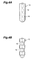
- the unitary optical fiber 110 in which Raman gain coefficient g(z), effective area A eff (z), Raman efficiency coefficient g(z)/A eff (z), or transmission loss ⁇ p changes in the longitudinal direction can be manufactured if the optical fiber preform 10 to be prepared beforehand is processed as shown in Figs.
- the optical fiber preform 10 shown in Fig. 4A has a structure in which, while the outside diameter of the region 14 to become the cladding parts is held constant, the outside diameter of the region 12 to become the core part is changed along the longitudinal direction thereof.
- the optical fiber preform 10 shown in Fig. 4B has a structure in which; while the outside diameter of the region 12 to become the core part is held constant, the outside diameter of the region 14 to become the cladding parts is changed along the longitudinal direction thereof.
- the wavelength band of optical signal is 1.3 ⁇ m or 1.55 ⁇ m, for example. If the signal wavelength band is a 1.3- ⁇ m band, then the pumping light wavelength band is from 1.15 ⁇ m to 1.3 ⁇ m. If the signal wavelength band is a 1.55- ⁇ m band, then the pumping light wavelength band is from 1.4 ⁇ m to 1.5 ⁇ m.
- the optical fiber 110 has a zero-dispersion wavelength in the wavelength band of pumping light at a given point. In this case, the efficiency in use of the wavelength band of optical signal can be enhanced.
- the optical fiber 110 has a zero-dispersion wavelength in the wavelength band of optical signal at a given point. In this case, the amount of accumulated dispersion can be kept low when the optical signal propagates through the optical fiber 110, whereby the waveform deterioration can be suppressed.
- the group velocity of optical signals at a given point of the optical fiber 110 is substantially identical to the group velocity of pumping light supplied forward. In this case, the optical signal can be subjected to Raman amplification most effectively.
- the pumping light supplied to the optical fiber 110 includes at least two polarized waves orthogonal to each other. In this case, Raman amplification independent of the state of polarization of optical signal is achieved.
- FIGs. 5A to 5D are explanatory views of the optical transmission system 200 and optical fiber 210 in accordance with the second embodiment.
- Fig. 5A shows the schematic configuration of the optical transmission system 200;
- Fig. 5B shows the distribution of effective area A eff (z) in the optical fiber 110;
- Fig. 5C shows the distribution of pumping light power in the optical fiber 210;
- Fig. 5D shows the distribution of optical signal power in the optical fiber 210.
- the optical transmission system 200 comprises the optical fiber 210, which is an optical transmission line enabling Raman amplification of an optical signal when pumping light is supplied thereto; an pumping light source 222 for outputting the pumping light; and a multiplexer 232 for introducing the pumping light to the optical fiber 210.
- the pumping light outputted from the pumping light source 222 is supplied backward to the optical fiber 210 by way of an optical fiber 294 and the multiplexer 232.
- the optical signal inputted to the optical fiber 210 is subjected to Raman amplification while propagating through the optical fiber 210. Then, the optical signal subjected to Raman amplification further propagates through an optical fiber 292 by way of the multiplexer 232.
- Raman gain coefficient g(z) is substantially constant with respect to z
- the optical transmission system 200 can lower the effective loss in the optical fiber 210. Also, at any point of the optical fiber 210, it can restrain the optical signal power from increasing to such an extent that optical Kerr effects occur remarkably and from decreasing to such an extent that the SN ratio deteriorates greatly. Further, it can fully secure the optical signal power P s (L) at the end point of the optical fiber 210.
- the broken curve in Fig. 5D indicates the distribution of optical signal power P s (z) when the effective area A eff (z) is assumed to be constant regardless of position z. In this case, the optical signal power P s (L) becomes so low at the end point of the optical fiber 210 that a receiving error is likely to occur.
- it is designed such that, while keeping the Raman gain coefficient g (z) substantially constant, the region attaining the minimum value of effective area A eff (z) resides in a region, yielding a lower pumping light power, separated by a predetermined distance in the advancing direction of pumping light from the end portion 212 (z L) where the pumping light is supplied.
- FIGs. 6A to 6D are explanatory views of the optical transmission system 300 and optical fibers 311 to 313 in accordance with the third embodiment.
- Fig. 6A shows the schematic configuration of the optical transmission system 300;
- Fig. 6B shows the distribution of Raman efficiency coefficient g(z)/A eff (z) in the optical fibers 311 to 313;
- Fig. 6C shows the distribution of pumping light power in the optical fibers 311 to 313;
- Fig. 6D shows the distribution of optical signal power in the optical fibers 311 to 313.
- the optical transmission system 300 comprises the optical fibers 311 to 313, which constitute an optical transmission line enabling Raman amplification of an optical signal when pumping light is supplied thereto; pumping light sources 321, 322 for outputting the pumping light; and multiplexers 331, 332 for introducing the pumping light to the optical fibers 311 to 313.
- the pumping light outputted from the pumping light source 321 is supplied forward to the optical fibers 311 to 313 by way of an optical fiber 393 and the multiplexer 331.
- the pumping light outputted from the pumping light source 322 is supplied backward to the optical fibers 311 to 313 by way of an optical fiber 394 and the multiplexer 332.
- the pumping light is bidirectionally supplied to the optical fibers 311 to 313.
- the optical signal having reached the multiplexer 331 by propagating through an optical fiber 391 is fed into the optical fiber 311 by way of the multiplexer 331 and is subjected to Raman amplification while propagating through the optical fibers 311 to 313. Then, the optical signal subjected to Raman amplification further propagates through an optical fiber 392 by way of the multiplexer 332.
- the Raman efficiency coefficient g(z)/A eff (z) is the lowest in the optical fibers 311 and 313 at both ends including end portions 316, 317 where the pumping light is supplied, and is the highest in the center optical fiber 312 separated by a predetermined distance from the end portions 316, 317.
- the effective loss in the optical fibers 311 to 313 can be made smaller in the optical transmission system 300.
- the broken curve in Fig. 6D indicates the distribution of optical signal power P s (z) in the case where the optical fiber 311 or optical fiber 313 is disposed in place of the optical fiber 312.
- the optical transmission system 300 is designed such that the Raman gain ⁇ g is the lowest in the optical fiber 311 or 313 including the region with the highest pumping light power among the optical fibers 311 to 313.
- the optical fiber 312 including the region with the maximum value of Raman efficiency coefficient g(z)/A eff (z) be coupled to the optical fibers 311, 313 so as to be held therebetween as shown in Fig. 6B.
- the optical fiber 312 including the region with the maximum value of Raman gain coefficient g(z) be coupled to the optical fibers 311, 313 so as to be held therebetween.
- the optical fiber 312 including the region with the minimum value of effective area A eff (z) be coupled to the optical fibers 311, 313 so as to be held therebetween.
- the optical fiber 312 including the region with the minimum value of transmission loss ⁇ p at an pumping light wavelength be coupled to the optical fibers 311, 313 so as to be held therebetween.
- the optical fiber 311 or 313 is an optical fiber whose core region is not intentionally doped with impurities, i.e., so-called pure silica core optical fiber. Since the pure silica core optical fiber yields lower transmission loss ⁇ p and Raman efficiency coefficient g(z)/A eff (z) than conventional optical fibers whose core region is doped with Ge do, it can favorably be used in a region with a higher pumping light power including the end portions 316, 317 where the pumping light is supplied.
- R1 be the length of the optical fiber 312 including the region with the minimum value of effective area among the optical fibers 311 to 313,
- R2 be the length of the optical fibers 311, 312 having the end portions 316, 317 where the pumping light is supplied
- R3 be the length of the optical waveguide region excluding the optical fiber 312 with the minimum value of effective area in the optical transmission line constituted by the optical fibers 311 to 313, it is preferred that R2 be 10 km or less and R1 ⁇ 4 ⁇ R3.
- R1 be the length of the optical fiber 312 including the region with the minimum value of effective area among the optical fibers 311 to 313, and R2 be the length of the optical fibers 311, 312 having the end portions 316, 317 where the pumping light is supplied, it is preferred that R2 be 10 km or greater and R1 ⁇ R2/4.
- optical fibers 314, 315 may be interposed between the optical fibers 311 and 312 and between the optical fibers 312 and 313, respectively.
- FIGs. 8A to 8D are explanatory views of the optical transmission system 400 and optical fibers 411, 412 in accordance with the fourth embodiment.
- Fig. 8A shows the schematic configuration of the optical transmission system 400;
- Fig. 8B shows the distribution of transmission loss ⁇ p at an pumping light wavelength in the optical fibers 411, 412;
- Fig. 8C shows the distribution of pumping light power in the optical fibers 411, 412;
- Fig. 8D shows the distribution of optical signal power in the optical fibers 411, 412.
- the optical transmission system 400 comprises the optical fibers 411, 412, which constitute an optical transmission line enabling Raman amplification of an optical signal when pumping light is supplied thereto; an pumping light source 422 for outputting the pumping light; and a multiplexer 432 for introducing the pumping light to the optical fibers 411, 412.
- the pumping light outputted from the pumping light source 422 is supplied backward to the optical fibers 411, 412 by way of an optical fiber 494 and the multiplexer 432.
- the optical signal fed into the optical fiber 411 is subjected to Raman amplification while propagating through the optical fibers 411, 412. Then, the optical signal subjected to Raman amplification further propagates through an optical fiber 492 by way of the multiplexer 432.
- the distribution of transmission loss ⁇ p at the pumping light wavelength in the optical fibers 411, 412 is such that the transmission loss is the greatest in the optical fiber 412 including the end portion 415 where the pumping light is supplied, and is the smallest in the optical fiber 411 farther from the multiplexer 432.
- the pumping light power is higher in the optical fiber 411 as compared with the case where both fibers have the same transmission loss ⁇ p (the broken curve in Fig. 8C).
- the effective loss in the optical fibers 411, 412 can be made smaller in the optical transmission system 400.
- the broken curve in Fig. 8D indicates the distribution of optical signal power P s (z) in the case where the transmission loss of the optical fiber 411 at the pumping light wavelength is supposed to be identical to that of the optical fiber 412.
- the optical transmission system 400 in accordance with this embodiment is designed such that the Raman gain ⁇ g is the lowest in the optical fiber 412 with the highest pumping light power including the end portion 415 where the pumping light is supplied in the optical fibers 411, 412.
- the optical fiber 411 including the region with the maximum value of Raman efficiency coefficient g(z)/A eff (z) and the optical fiber 412 be coupled to each other so as to constitute the optical transmission line.
- the optical fiber 411 including the region with the maximum value of Raman gain coefficient g(z) and the optical fiber 412 be coupled to each other so as to constitute the optical transmission line.
- the optical fiber 411 including the region with the minimum value of effective area A eff (z) and the optical fiber 412 be coupled to each other so as to constitute the optical transmission line.
- the optical fiber 411 including the region with the minimum value of transmission loss ⁇ p at the pumping light wavelength and the optical fiber 412 be coupled to each other so as to constitute the optical transmission line.
- another optical fiber 413 may be interposed between the optical fibers 411 and 412.
- FIGs. 10A to 10D are explanatory views of the optical transmission system 500 and optical fibers 511 to 513 in accordance with the fifth embodiment.
- Fig. 10A shows the schematic configuration of the optical transmission system 500;
- Fig. 10B shows the distribution of effective area A eff (z) in the optical fibers 511 to 513;
- Fig. 10C shows the distribution of Raman gain coefficient g(z) in the optical fibers 511 to 513;
- Fig. 10D shows the distribution of optical signal power in the optical fibers 511 to 513.
- the optical transmission system 500 comprises the optical fibers 511 to 513, which constitute an optical transmission line enabling Raman amplification of an optical signal when pumping light is supplied thereto; pumping light sources 521, 522 for outputting the pumping light; and multiplexers 531, 532 for introducing the pumping light to the optical fibers 511 to 513.
- Each of the optical fibers 511 and 513 is a single-mode optical fiber having a zero-dispersion wavelength near a wavelength of 1.3 ⁇ m.
- the optical fiber 512 is a dispersion-shifted optical fiber having a zero-dispersion wavelength at a wavelength slightly longer (or shorter) than a wavelength of 1.55 ⁇ m.
- the pumping light outputted from the pumping light source 521 is supplied forward to the optical fibers 511 to 513 by way of an optical fiber 593 and the multiplexer 531.
- the pumping light outputted from the pumping light source 522 is supplied backward to the optical fibers 511 to 513 by way of an optical fiber 594 and the multiplexer 532.
- the pumping light is bidirectionally supplied to the optical fibers 511 to 513.
- the optical signal having reached the multiplexer 531 by propagating through an optical fiber 591 is fed into the optical fiber 511 by way of the multiplexer 531 and is subjected to Raman amplification while propagating through the optical fibers 511 to 513. Then, the optical signal subjected to Raman amplification further propagates through an optical fiber 592 by way of the multiplexer 532.
- the distribution of effective area A eff (z) is such that the effective area is larger in the optical fibers 511, 513 including end portions 516, 517 where the pumping light is supplied, and is smaller in the center optical fiber 512.
- the distribution of Raman gain coefficient g(z) is such that the gain coefficient is lower in the optical fibers 511, 513 including the end portions 516, 517 where the pumping light is supplied, and is higher in the center optical fiber 512.
- the effective loss in the optical fibers 511 to 513 can be made smaller in the optical transmission system 500.
- the wavelength of optical signal is 1.55 ⁇ m or 1.58 ⁇ m
- a semiconductor laser light source outputting laser light having a wavelength of 1.48 ⁇ m is preferably used as each of the pumping light sources 521, 522.
- the respective wavelengths of optical signals in the optical fibers 511 to 513 yield power distributions different from each other. It is because of the fact that, as Fig. 11 shows the wavelength dependence of Raman gain, the Raman gain at a wavelength of 1.58 ⁇ m is greater than that at a wavelength of 1.55 ⁇ m.
- the optical signal power would neither increase to such an extent that optical Kerr effects occur remarkably nor decrease to such an extent that the SN ratio deteriorates greatly.
- Another wavelength (e.g., 1.43 ⁇ m) of pumping light may also be introduced so as to effect wavelength division multiplexing of pumping light, whereby the difference in power between optical signals can be reduced.
- the broken curve in Fig. 10D indicates the case where the pumping light source 522 employs pumping light at a wavelength of 1.43 ⁇ m for multiplexing.
- optical transmission system 100 to 500 in accordance with the above-mentioned first to fifth embodiments will be explained in further detail with reference to specific examples.
- the optical fiber 110 is a unitary optical fiber.
- the optical fiber 210 is a unitary optical fiber.
- each of the optical fibers 311 and 313 is a single-mode optical fiber (SMF) having, with respect to a signal wavelength of 1550 nm, an effective area of 80 ⁇ m 2 and a dispersion of 17 ps/nm/km.
- the optical fiber 312 is a dispersion-shifted optical fiber (DSF) having, with respect to a signal wavelength of 1550 nm, an effective area of 50 ⁇ m 2 and a dispersion of -1 ps/nm/km.
- DSF dispersion-shifted optical fiber
- Each of the optical fibers 311 and 313 has a length of 20 km, whereas the optical fiber 312 has a length of 10 km.
- each of the optical fibers 311 and 313 is a dispersion-shifted optical fiber whose zero-dispersion wavelength is on the shorter wavelength side from a wavelength of 1550 nm (NZDSF) having, with respect to a signal wavelength of 1550 nm, an effective area of 50 ⁇ m 2 and a dispersion of -5 ps/nm/km.
- NZDSF 1550 nm
- the optical fiber 312 is a dispersion-shifted optical fiber whose zero-dispersion wavelength is on the longer wavelength side from a wavelength of 1550 nm (NZDSF) having, with respect to a signal wavelength of 1550 nm, an effective area of 45 ⁇ m 2 and a dispersion of 5 ps/nm/km.
- NZDSF 1550 nm
- Each of the optical fibers 311 and 313 has a length of 10 km, whereas the optical fiber 312 has a length of 20 km.
- each of the optical fibers 311 and 313 is a pure silica core optical fiber (ZF) having, with respect to a signal wavelength of 1550 nm, an effective area of 80 ⁇ m 2 and a dispersion of 18 ps/nm/km.
- the optical fiber 312 is a dispersion-shifted optical fiber whose zero-dispersion wavelength is on the shorter wavelength side from a wavelength of 1550 nm (NZDSF) having, with respect to a signal wavelength of 1550 nm, an effective area of 55 ⁇ m 2 and a dispersion of 3 ps/nm/km.
- NZDSF wavelength of 1550 nm
- Each of the optical fibers 311 to 313 has a length of 20 km.
- each of the optical fibers 311 and 313 is a single-mode optical fiber (SMF) having, with respect to a signal wavelength of 1550 nm, an effective area of 120 ⁇ m 2 and a dispersion of 20 ps/nm/km.
- the optical fiber 312 is a dispersion-compensating optical fiber (DCF) having, with respect to a signal wavelength of 1550 nm, an effective area of 23 ⁇ m 2 and a dispersion of -30 ps/nm/km.
- DCF dispersion-compensating optical fiber
- Each of the optical fibers 311 and 313 has a length of 15 km, whereas the optical fiber 312 has a length of 20 km.
- a fifth specific example of the optical transmission system 300 comprises a plurality of optical transmission systems, each shown in Fig. 6A, connected in series as shown in Fig. 12.
- the optical transmission system 300 shown in Fig. 12 comprises a plurality of transmitters 361 for transmitting respective optical signals having wavelengths different from each other, and a plurality of receivers 363 for receiving respective optical signals having wavelengths different from each other.
- a plurality of optical signals transmitted from their corresponding transmitters 361 are multiplexed by a multiplexer 351.
- multiplexed optical signal is sent out to an optical fiber 391' after its power is attenuated by an attenuator 341.
- the optical signal propagating through the optical fiber 391' is fed, by way of a multiplexer 331', into an optical transmission line constituted by optical fibers 311' to 313' and is subjected to Raman amplification while propagating through this optical transmission line.
- the optical signal subjected to Raman amplification further propagates through an optical fiber 392' by way of a multiplexer 332'.
- the optical signal propagating through the optical fiber 392' is fed into an optical fiber 391".
- the optical signal propagating through the optical fiber 391" is fed, by way of a multiplexer 331", into an optical transmission line constituted by optical fibers 311" to 313" and is subjected to Raman amplification while propagating through this optical transmission line.
- the optical signal subjected to Raman amplification further propagates through an optical fiber 392" by way of a multiplexer 332".
- the optical signal propagating through the optical fiber 392" is demultiplexed by a demultiplexer 353 into optical signals having wavelengths different from each other, which are then received by their corresponding receivers 363.
- each of the optical fibers 311', 311" and optical fibers 313', 313" is a single-mode optical fiber (SMF) having, with respect to a signal wavelength of 1550 nm, an effective area of 80 ⁇ m 2 and a dispersion of 17 ps/nm/km.
- Each of the optical fibers 312', 312" is a dispersion-shifted optical fiber (DSF) having, with respect to a signal wavelength of 1550 nm, an effective area of 50 ⁇ m 2 and a dispersion of -1 ps/nm/km.
- DSF dispersion-shifted optical fiber
- Each of the optical fibers 311', 311" and optical fibers 313', 313" has a length of 18 km, whereas each of the optical fibers 312', 312" has a length of 14 km.
- optical transmission system 300 transmission characteristics were evaluated at a transmission speed of 10 Gb/s by use of eight optical signals (having a center wavelength of 1550 nm) at intervals of 100 GHz.
- the output of the attenuator 341 was -20 dBm per channnel.
- Each of the pumping light sources 321', 322', 321", 322" was of a wavelength division multiplexing type in which a single unit employed pumping light having a wavelength of 1430 nm and pumping light having a wavelength of 1480 nm, whereas the total output power of single unit was 27 dBm. As a result, it was possible to carry out error-free transmission in all the channels (though dispersion compensation was effected for each optical signal on the receiver side).
- the error-free transmission refers to one in which the curve of bit error rate (BER) does not become a floor state.
- the floor state refers to a state where BER would not decrease from a certain level even if the received power is raised as indicated by the broken curve in Fig. 13.
- the penalty indicates the degree of deterioration in receiving sensitivity after an optical transmission line is inserted with respect to the BER characteristic in the case where the receiver and transmitter are directly connected to each other (i.e., Back to Back characteristic, indicatedby black triangles in Fig. 13).
- a typical example thereof is the level difference T at a BER of 10 -9 .
- a sixth specific example of the optical transmission system 300 relates to an optical transmission system in which, as shown in Fig. 7, an optical fiber 314 is disposed between optical fibers 311 and 312, whereas an optical fiber 315 is disposed between optical fibers 312 and 313.
- Each of the optical fibers 311 and 313 is a single-mode optical fiber (SMF) having, with respect to a signal wavelength of 1550 nm, an effective area of 80 ⁇ m 2 and a dispersion of 17 ps/nm/km.
- SMF single-mode optical fiber
- the optical fiber 312 is a dispersion-compensating optical fiber (DCF) having, with respect to a signal wavelength of 1550 nm, an effective area of 16 ⁇ m 2 and a dispersion of -80 ps/nm/km.
- DCF dispersion-compensating optical fiber
- Each of the optical fibers 314 and 315 is a dispersion-shifted optical fiber whose zero-dispersion wavelength is on the shorter wavelength side from a wavelength of 1550 nm (NZDSF) having, with respect to a signal wavelength of 1550 nm, an effective area of 50 ⁇ m 2 and a dispersion of 4 ps/nm/km.
- NZDSF wavelength of 1550 nm
- Each of the optical fibers 311 and 313 has a length of 20 km
- the optical fiber 312 has a length of 10 km
- each of the optical fibers 314 and 315 has a length of 20 km.
- the optical fiber 411 is a dispersion-shifted optical fiber (DSF) having, with respect to a signal wavelength of 1550 nm, an effective area of 50 ⁇ m 2 and a dispersion of -1 ps/nm/km.
- the optical fiber 412 is a single-mode optical fiber (SMF) having, with respect to a signal wavelength of 1550 nm, an effective area of 80 ⁇ m 2 and a dispersion of 17 ps/nm/km.
- the optical fiber 411 has a length of 10 km, whereas the optical fiber 412 has a length of 25 km.
- the optical fiber 411 is a dispersion-shifted optical fiber whose zero-dispersion wavelength is on the shorter wavelength side from a wavelength of 1550 nm (NZDSF) having, with respect to a signal wavelength of 1550 nm, an effective area of 45 ⁇ m 2 and a dispersion of 5 ps/nm/km.
- the optical fiber 412 is a dispersion-shifted optical fiber whose zero-dispersion wavelength is on the longer wavelength side from a wavelength of 1550 nm (NZDSF) having, with respect to a signal wavelength of 1550 nm, an effective area of 50 ⁇ m 2 and a dispersion of -5 ps/nm/km.
- Each of the optical fibers 411 and 412 has a length of 20 km.
- the optical fiber 411 is a dispersion-shifted optical fiber whose zero-dispersion wavelength is on the shorter wavelength side from a wavelength of 1550 nm (NZDSF) having, with respect to a signal wavelength of 1550 nm, an effective area of 50 ⁇ m 2 and a dispersion of 3 ps/nm/km.
- the optical fiber 412 is a pure silica core optical fiber (ZF) having, with respect to a signal wavelength of 1550 nm, an effective area of 80 ⁇ m 2 and a dispersion of 18 ps/nm/km.
- the optical fiber 411 has a length of 15 km, whereas the optical fiber 412 has a length of 25 km.
- the optical fiber 411 is a dispersion-compensating optical fiber (DCF) having, with respect to a signal wavelength of 1550 nm, an effective area of 22 ⁇ m 2 and a dispersion of -40 ps/nm/km.
- the optical fiber 412 is a single-mode optical fiber (SMF) having, with respect to a signal wavelength of 1550 nm, an effective area of 80 ⁇ m 2 and a dispersion of 17 ps/nm/km.
- the optical fiber 411 has a length of 20 km, whereas the optical fiber 412 has a length of 15 km.
- the optical transmission system 400 shown in Fig. 8A further comprises an amplifier constituted by an optical fiber 451 doped with erbium (Er) and a receiving section 453.
- the optical fiber 451 has one end coupled to the optical fiber 492 by fusion or the like, and the other end coupled to the receiving section 453.
- the optical fiber 411 is a dispersion-shifted optical fiber (DSF) having, with respect to a signal wavelength of 1550 nm, an effective area of 50 ⁇ m 2 and a dispersion of -1 ps/nm/km.
- the optical fiber 412 is a single-mode optical fiber (SMF) having, with respect to a signal wavelength of 1550 nm, an effective area of 80 ⁇ m 2 and a dispersion of 17 ps/nm/km.
- SMF single-mode optical fiber
- optical transmission system 400 transmission characteristics were evaluated at a transmission speed of 2.5 Gb/s by use of four optical signals (having a center wavelength of 1550 nm) at intervals of 100 GHz. The result thereof is shown in Fig. 15.
- Back to Back characteristics were indicated by black triangles
- transmission characteristics in the case where the SN ratio of optical signal was 18 dB at its exit end 417 were indicated by black circles
- transmission characteristics in the case where the SN ratio of optical signal was 16 dB at the exit end 417 were indicated by black squares.
- the penalty T became 0.5 dB or lower, whereby it was possible for the optical transmission system 400 to secure stable operations.
- the optical transmission system 400 shown in Fig. 8A further comprises a transmitting section 455 and a receiving section 453.
- the transmitting section 455 has an end portion 414 coupled to the optical fiber 411, whereas the receiving section 453 is coupled to the optical fiber 492.
- the optical fiber 411 is a dispersion-compensating optical fiber (DCF) having, with respect to a signal wavelength of 1550 nm, an effective area of 40 ⁇ m 2 and a dispersion of -8 ps/nm/km.
- the optical fiber 412 is a single-mode optical fiber (SMF) having, with respect to a signal wavelength of 1550 nm, an effective area of 80 ⁇ m 2 and a dispersion of 17 ps/nm/km.
- the optical fiber 411 has a length of 31.9 km, whereas the optical fiber 412 has a length of 15 km.
- the dispersion of the optical transmission line constituted by the optical fibers 411 and 412 is substantially 0 ps/nm/km.
- optical transmission system 400 transmission characteristics were evaluated at a transmission speed of 10 Gb/s by use of eight optical signals (having a center wavelength of 1550 nm) at intervals of 100 GHz. As a result, it was possible to attain a penalty of 1 dB or less in the case where the pumping light power was controlled so as to become 600 mW or higher.
- DCF dispersion-compensating optical fiber
- a seventh specific example of the optical transmission system 400 relates to an optical transmission system in which an optical fiber 413 is disposed between optical fibers 411 and 412 as shown in Fig. 9.
- the optical fiber 411 is a dispersion-compensating optical fiber (DCF) having, with respect to a signal wavelength of 1550 nm, an effective area of 30 ⁇ m 2 and a dispersion of -20 ps/nm/km.
- the optical fiber 412 is a single-mode optical fiber (SMF) having, with respect to a signal wavelength of 1550 nm, an effective area of 80 ⁇ m 2 and a dispersion of 17 ps/nm/km.
- DCF dispersion-compensating optical fiber
- SMF single-mode optical fiber
- the optical fiber 413 is a dispersion-shifted optical fiber whose zero-dispersion wavelength is on the longer wavelength side from a wavelength of 1550 nm (NZDSF) having, with respect to a signal wavelength of 1550 nm, an effective area of 45 ⁇ m 2 and a dispersion of -4 ps/nm/km.
- the optical fiber 411 has a length of 10 km, whereas each of the optical fibers 412 and 413 has a length of 20 km.
- the optical transmission line in accordance with the present invention since the optical transmission line in accordance with the present invention has a smaller Raman amplification effect in the region with a higher pumping light power, and a greater Raman amplification effect in the region with a lower pumping light power, it can restrain, at any point of the optical transmission line, the optical signal from enhancing its power to such an extent that optical Kerr effects occur remarkably and from lowering its power to such an extent that the SN ratio greatly deteriorates, and can fully secure the power of optical signal at the end point of optical transmission line. Also, it can lower the effective loss in the optical transmission line.
Landscapes
- Physics & Mathematics (AREA)
- Electromagnetism (AREA)
- Engineering & Computer Science (AREA)
- Plasma & Fusion (AREA)
- Optics & Photonics (AREA)
- Optical Modulation, Optical Deflection, Nonlinear Optics, Optical Demodulation, Optical Logic Elements (AREA)
- Optical Communication System (AREA)
- Lasers (AREA)
Applications Claiming Priority (3)
| Application Number | Priority Date | Filing Date | Title |
|---|---|---|---|
| JP36756899 | 1999-12-24 | ||
| JP36756899 | 1999-12-24 | ||
| PCT/JP2000/005343 WO2001048550A1 (fr) | 1999-12-24 | 2000-08-09 | Ligne a transmission optique, procede de fabrication de ligne a transmission optique et systeme de transmission optique |
Publications (3)
| Publication Number | Publication Date |
|---|---|
| EP1164412A1 true EP1164412A1 (fr) | 2001-12-19 |
| EP1164412A4 EP1164412A4 (fr) | 2005-07-27 |
| EP1164412B1 EP1164412B1 (fr) | 2007-10-17 |
Family
ID=18489638
Family Applications (1)
| Application Number | Title | Priority Date | Filing Date |
|---|---|---|---|
| EP00951920A Expired - Lifetime EP1164412B1 (fr) | 1999-12-24 | 2000-08-09 | Ligne à transmission optique à amplification Raman et système de transmission optique |
Country Status (7)
| Country | Link |
|---|---|
| US (2) | US6795235B1 (fr) |
| EP (1) | EP1164412B1 (fr) |
| AU (1) | AU783200B2 (fr) |
| CA (1) | CA2365109A1 (fr) |
| DE (1) | DE60036791T2 (fr) |
| TW (1) | TW480351B (fr) |
| WO (1) | WO2001048550A1 (fr) |
Cited By (1)
| Publication number | Priority date | Publication date | Assignee | Title |
|---|---|---|---|---|
| CN108649416A (zh) * | 2018-06-27 | 2018-10-12 | 武汉光迅科技股份有限公司 | 一种分布式拉曼光纤放大器中光纤长度对最大增益影响因子获取方法和装置 |
Families Citing this family (14)
| Publication number | Priority date | Publication date | Assignee | Title |
|---|---|---|---|---|
| JP2003066261A (ja) * | 2001-08-27 | 2003-03-05 | Sumitomo Electric Ind Ltd | 光伝送路および光通信システム |
| JP2003066262A (ja) * | 2001-08-29 | 2003-03-05 | Sumitomo Electric Ind Ltd | 光伝送路および光通信システム |
| JP3903768B2 (ja) * | 2001-10-31 | 2007-04-11 | 日本電気株式会社 | 光ファイバ伝送システムとラマン利得制御装置、及びラマン利得制御方法 |
| JP3873779B2 (ja) * | 2002-03-04 | 2007-01-24 | 富士通株式会社 | ラマン増幅方式の光通信システム |
| US20060209392A1 (en) * | 2003-08-11 | 2006-09-21 | Renato Caponi | Multi-stage optical amplifier optimized with respect to noise, gain and bandwidth |
| ATE482577T1 (de) | 2004-10-27 | 2010-10-15 | Epcos Ag | Verringerung der luftdämpfung in einer mems- vorrichtung |
| JP4602739B2 (ja) * | 2004-11-01 | 2010-12-22 | 昭和電線ケーブルシステム株式会社 | 波長多重伝送システム |
| JP2007005484A (ja) * | 2005-06-22 | 2007-01-11 | Fujitsu Ltd | 光増幅装置及び光ファイバ |
| JP2008273769A (ja) * | 2007-04-26 | 2008-11-13 | Hitachi Cable Ltd | 光ファイバ及びその製造方法並びに光ファイバ製造装置 |
| US9484706B1 (en) * | 2012-06-12 | 2016-11-01 | Nlight, Inc. | Tapered core fiber manufacturing methods |
| WO2016032420A1 (fr) * | 2014-08-25 | 2016-03-03 | Halliburton Energy Services, Inc. | Câble à fibre optique hybride pour une détection distribuée |
| WO2020092707A2 (fr) * | 2018-11-01 | 2020-05-07 | Ofs Fitel, Llc | Source de lumière à balayage de longueur d'onde |
| JP2023507988A (ja) * | 2019-12-18 | 2023-02-28 | オーエフエス ファイテル,エルエルシー | 増幅中空コアファイバ伝送 |
| CN114978309A (zh) * | 2022-07-01 | 2022-08-30 | 国网西藏电力有限公司 | 一种拉曼增益系数的测量方法和装置 |
Family Cites Families (21)
| Publication number | Priority date | Publication date | Assignee | Title |
|---|---|---|---|---|
| JPS59126696A (ja) * | 1983-01-10 | 1984-07-21 | Nec Corp | 光通信用光増幅装置 |
| JPS6114624A (ja) * | 1984-06-29 | 1986-01-22 | Nippon Telegr & Teleph Corp <Ntt> | 光フアイバによる光増幅装置 |
| JPH0310204A (ja) * | 1989-06-07 | 1991-01-17 | Fujikura Ltd | 非線形光ファイバおよびその製造法 |
| US5058974A (en) * | 1989-10-06 | 1991-10-22 | At&T Bell Laboratories | Distributed amplification for lightwave transmission system |
| US5039199A (en) * | 1989-12-29 | 1991-08-13 | At&T Bell Laboratories | Lightwave transmission system having remotely pumped quasi-distributed amplifying fibers |
| JP2584151B2 (ja) * | 1991-06-11 | 1997-02-19 | 株式会社フジクラ | 光ファイバ |
| EP0590379B1 (fr) * | 1992-09-30 | 1997-07-02 | Siemens Aktiengesellschaft | Dispositif de transmission optique pour la transmission de signaux optiques en multiplexage de longueur d'onde sur une multiplicité de porteuses optiques à longueurs d'onde adjacentes |
| US6191877B1 (en) * | 1995-02-17 | 2001-02-20 | Lucent Technologies Inc. | WDM optical fiber system using Raman amplification |
| EP0734105B1 (fr) * | 1995-03-20 | 2004-09-29 | Fujitsu Limited | Amplificateur à fibre optique et module à fibre pour la compensation de la dispersion pour amplificateur à fibre optique |
| JPH0983441A (ja) * | 1995-09-19 | 1997-03-28 | Matsushita Electric Ind Co Ltd | 送受信装置 |
| JPH0996843A (ja) * | 1995-09-29 | 1997-04-08 | Sumitomo Electric Ind Ltd | 光中継伝送装置及び光通信方法 |
| CA2195614C (fr) | 1996-02-16 | 2005-06-28 | George F. Wildeman | Cable optique symetrique a gestion de dispersion et systeme associe |
| JP3403288B2 (ja) * | 1996-02-23 | 2003-05-06 | 古河電気工業株式会社 | 光増幅装置 |
| JPH10200509A (ja) * | 1997-01-10 | 1998-07-31 | Nippon Telegr & Teleph Corp <Ntt> | 光伝送システム |
| US6081366A (en) * | 1997-08-28 | 2000-06-27 | Lucent Technologies Inc. | Optical fiber communication system with a distributed Raman amplifier and a remotely pumped er-doped fiber amplifier |
| US5887093A (en) * | 1997-09-12 | 1999-03-23 | Lucent Technologies Incorporated | Optical fiber dispersion compensation |
| JPH11204866A (ja) * | 1998-01-19 | 1999-07-30 | Kdd | 波長多重信号増幅中継器および該中継器を用いた光通信伝送路 |
| JPH11208998A (ja) * | 1998-01-26 | 1999-08-03 | Sumitomo Electric Ind Ltd | 光ファイバの巻き取り方法 |
| US6052219A (en) * | 1999-02-16 | 2000-04-18 | Tyco Submarine Systems Ltd. | Wide bandwidth Raman amplifier capable of employing pump energy spectrally overlapping the signal |
| US6366728B1 (en) * | 2000-01-28 | 2002-04-02 | Mci Worldcom, Inc. | Composite optical fiber transmission line method |
| JP2002014383A (ja) * | 2000-06-28 | 2002-01-18 | Kdd Submarine Cable Systems Inc | ラマン増幅器 |
-
2000
- 2000-08-09 EP EP00951920A patent/EP1164412B1/fr not_active Expired - Lifetime
- 2000-08-09 DE DE60036791T patent/DE60036791T2/de not_active Expired - Lifetime
- 2000-08-09 CA CA002365109A patent/CA2365109A1/fr not_active Abandoned
- 2000-08-09 WO PCT/JP2000/005343 patent/WO2001048550A1/fr active IP Right Grant
- 2000-08-09 AU AU64731/00A patent/AU783200B2/en not_active Ceased
- 2000-08-11 US US09/635,900 patent/US6795235B1/en not_active Expired - Lifetime
- 2000-08-25 TW TW089117180A patent/TW480351B/zh not_active IP Right Cessation
-
2004
- 2004-04-29 US US10/834,189 patent/US7085040B2/en not_active Expired - Fee Related
Non-Patent Citations (2)
| Title |
|---|
| No further relevant documents disclosed * |
| See also references of WO0148550A1 * |
Cited By (2)
| Publication number | Priority date | Publication date | Assignee | Title |
|---|---|---|---|---|
| CN108649416A (zh) * | 2018-06-27 | 2018-10-12 | 武汉光迅科技股份有限公司 | 一种分布式拉曼光纤放大器中光纤长度对最大增益影响因子获取方法和装置 |
| CN108649416B (zh) * | 2018-06-27 | 2019-09-13 | 武汉光迅科技股份有限公司 | 一种分布式拉曼光纤放大器中光纤长度对最大增益影响因子获取方法和装置 |
Also Published As
| Publication number | Publication date |
|---|---|
| EP1164412B1 (fr) | 2007-10-17 |
| US20040202437A1 (en) | 2004-10-14 |
| DE60036791T2 (de) | 2008-02-07 |
| TW480351B (en) | 2002-03-21 |
| DE60036791D1 (de) | 2007-11-29 |
| US7085040B2 (en) | 2006-08-01 |
| CA2365109A1 (fr) | 2001-07-05 |
| AU783200B2 (en) | 2005-10-06 |
| AU6473100A (en) | 2001-07-09 |
| EP1164412A4 (fr) | 2005-07-27 |
| WO2001048550A1 (fr) | 2001-07-05 |
| US6795235B1 (en) | 2004-09-21 |
Similar Documents
| Publication | Publication Date | Title |
|---|---|---|
| US6404964B1 (en) | Dispersion managed optical waveguide and system with distributed amplification | |
| EP1164412B1 (fr) | Ligne à transmission optique à amplification Raman et système de transmission optique | |
| US6782172B2 (en) | Optical fiber, optical transmission line and dispersion compensating module | |
| EP2822112B1 (fr) | Amplificateur de fibres dopées à l'erbium (EDFA) pompées à double revêtement haute puissance | |
| EP0862069A2 (fr) | Fibre optique | |
| US6941054B2 (en) | Optical transmission link with low slope, raman amplified fiber | |
| US6628872B2 (en) | Dispersion compensator and optical transmission system | |
| EP1314268B1 (fr) | Lien de transmission optique comportant des fibres a amplification raman ayant une faible pente | |
| EP1421418B1 (fr) | Fibre optique d'amplification dopee a l'erbium a haute absorption | |
| EP1278316B1 (fr) | Correcteur de dispersion | |
| US6618532B1 (en) | Optical transmission line | |
| US6724527B2 (en) | Optical amplifier and optical transmission system using same | |
| US6928221B2 (en) | Device for the compensation of chromatic dispersion | |
| US6687443B2 (en) | Optical fiber transmission line, optical cable, and optical transmission system | |
| US6898361B2 (en) | Dispersion-compensating optical fiber and optical transmission line | |
| US20030169986A1 (en) | Optical fiber, optical component, dispersion compensating fiber module, and optical communication system | |
| JP2005234192A (ja) | 分散補償ファイバ及びラマン増幅伝送システム | |
| JP2004198737A (ja) | 光ファイバおよびそれを用いた光伝送路 |
Legal Events
| Date | Code | Title | Description |
|---|---|---|---|
| PUAI | Public reference made under article 153(3) epc to a published international application that has entered the european phase |
Free format text: ORIGINAL CODE: 0009012 |
|
| 17P | Request for examination filed |
Effective date: 20010924 |
|
| AK | Designated contracting states |
Kind code of ref document: A1 Designated state(s): AT BE CH CY DE DK ES FI FR GB GR IE IT LI LU MC NL PT SE |
|
| RBV | Designated contracting states (corrected) |
Designated state(s): DE FR GB IT |
|
| A4 | Supplementary search report drawn up and despatched |
Effective date: 20050615 |
|
| RIC1 | Information provided on ipc code assigned before grant |
Ipc: H04B 10/17 20060101ALN20070330BHEP Ipc: G02F 1/35 20060101ALN20070330BHEP Ipc: H01S 3/30 20060101AFI20070330BHEP |
|
| RTI1 | Title (correction) |
Free format text: OPTICAL TRANSIMISSION LINE ENABLING RAMAN AMPLIFICATION AND OPTICAL TRANSMISSION SYSTEM |
|
| GRAP | Despatch of communication of intention to grant a patent |
Free format text: ORIGINAL CODE: EPIDOSNIGR1 |
|
| RIN1 | Information on inventor provided before grant (corrected) |
Inventor name: OKUNO, TOSHIAKI,C/O YOKOHAMA WORKS Inventor name: NISHIMURA, MASAYUKI,C/O YOKOHAMA WORKS |
|
| GRAS | Grant fee paid |
Free format text: ORIGINAL CODE: EPIDOSNIGR3 |
|
| GRAA | (expected) grant |
Free format text: ORIGINAL CODE: 0009210 |
|
| AK | Designated contracting states |
Kind code of ref document: B1 Designated state(s): DE FR GB IT |
|
| REG | Reference to a national code |
Ref country code: GB Ref legal event code: FG4D |
|
| REF | Corresponds to: |
Ref document number: 60036791 Country of ref document: DE Date of ref document: 20071129 Kind code of ref document: P |
|
| ET | Fr: translation filed | ||
| PLBE | No opposition filed within time limit |
Free format text: ORIGINAL CODE: 0009261 |
|
| STAA | Information on the status of an ep patent application or granted ep patent |
Free format text: STATUS: NO OPPOSITION FILED WITHIN TIME LIMIT |
|
| 26N | No opposition filed |
Effective date: 20080718 |
|
| REG | Reference to a national code |
Ref country code: GB Ref legal event code: 746 Effective date: 20121119 |
|
| REG | Reference to a national code |
Ref country code: DE Ref legal event code: R084 Ref document number: 60036791 Country of ref document: DE Effective date: 20121113 |
|
| PGFP | Annual fee paid to national office [announced via postgrant information from national office to epo] |
Ref country code: DE Payment date: 20140806 Year of fee payment: 15 |
|
| PGFP | Annual fee paid to national office [announced via postgrant information from national office to epo] |
Ref country code: FR Payment date: 20140808 Year of fee payment: 15 Ref country code: GB Payment date: 20140806 Year of fee payment: 15 |
|
| PGFP | Annual fee paid to national office [announced via postgrant information from national office to epo] |
Ref country code: IT Payment date: 20140709 Year of fee payment: 15 |
|
| REG | Reference to a national code |
Ref country code: DE Ref legal event code: R119 Ref document number: 60036791 Country of ref document: DE |
|
| GBPC | Gb: european patent ceased through non-payment of renewal fee |
Effective date: 20150809 |
|
| PG25 | Lapsed in a contracting state [announced via postgrant information from national office to epo] |
Ref country code: IT Free format text: LAPSE BECAUSE OF NON-PAYMENT OF DUE FEES Effective date: 20150809 |
|
| REG | Reference to a national code |
Ref country code: FR Ref legal event code: ST Effective date: 20160429 |
|
| PG25 | Lapsed in a contracting state [announced via postgrant information from national office to epo] |
Ref country code: DE Free format text: LAPSE BECAUSE OF NON-PAYMENT OF DUE FEES Effective date: 20160301 Ref country code: GB Free format text: LAPSE BECAUSE OF NON-PAYMENT OF DUE FEES Effective date: 20150809 |
|
| PG25 | Lapsed in a contracting state [announced via postgrant information from national office to epo] |
Ref country code: FR Free format text: LAPSE BECAUSE OF NON-PAYMENT OF DUE FEES Effective date: 20150831 |