EP1160858A2 - A board for manufacturing a bga and method of manufacturing semiconductor device using thereof - Google Patents
A board for manufacturing a bga and method of manufacturing semiconductor device using thereof Download PDFInfo
- Publication number
- EP1160858A2 EP1160858A2 EP01302530A EP01302530A EP1160858A2 EP 1160858 A2 EP1160858 A2 EP 1160858A2 EP 01302530 A EP01302530 A EP 01302530A EP 01302530 A EP01302530 A EP 01302530A EP 1160858 A2 EP1160858 A2 EP 1160858A2
- Authority
- EP
- European Patent Office
- Prior art keywords
- face
- manufacturing
- flat member
- board
- bonding pad
- Prior art date
- Legal status (The legal status is an assumption and is not a legal conclusion. Google has not performed a legal analysis and makes no representation as to the accuracy of the status listed.)
- Withdrawn
Links
- 239000004065 semiconductor Substances 0.000 title claims abstract description 138
- 238000004519 manufacturing process Methods 0.000 title claims abstract description 60
- 238000000034 method Methods 0.000 claims abstract description 63
- 238000005530 etching Methods 0.000 claims description 69
- 229920005989 resin Polymers 0.000 claims description 66
- 239000011347 resin Substances 0.000 claims description 66
- 239000000463 material Substances 0.000 claims description 26
- 229920002120 photoresistant polymer Polymers 0.000 claims description 23
- 238000007789 sealing Methods 0.000 claims description 22
- 239000011888 foil Substances 0.000 claims description 15
- 238000010276 construction Methods 0.000 claims description 10
- 238000000227 grinding Methods 0.000 claims description 10
- 229910017767 Cu—Al Inorganic materials 0.000 claims description 8
- 229910052737 gold Inorganic materials 0.000 claims description 8
- 229910052709 silver Inorganic materials 0.000 claims description 7
- 229910052759 nickel Inorganic materials 0.000 claims description 6
- 229910001030 Iron–nickel alloy Inorganic materials 0.000 claims description 4
- 239000000956 alloy Substances 0.000 claims description 4
- 229910052802 copper Inorganic materials 0.000 claims description 4
- 229910052763 palladium Inorganic materials 0.000 claims description 4
- 229910045601 alloy Inorganic materials 0.000 claims description 3
- 238000011049 filling Methods 0.000 claims description 3
- 239000011159 matrix material Substances 0.000 claims description 3
- 229910052782 aluminium Inorganic materials 0.000 claims description 2
- 230000000694 effects Effects 0.000 description 13
- RYGMFSIKBFXOCR-UHFFFAOYSA-N Copper Chemical compound [Cu] RYGMFSIKBFXOCR-UHFFFAOYSA-N 0.000 description 11
- 229910000679 solder Inorganic materials 0.000 description 11
- 239000010949 copper Substances 0.000 description 10
- 238000000465 moulding Methods 0.000 description 7
- 238000005498 polishing Methods 0.000 description 7
- 238000002955 isolation Methods 0.000 description 6
- 239000000853 adhesive Substances 0.000 description 5
- 230000001070 adhesive effect Effects 0.000 description 5
- 238000005219 brazing Methods 0.000 description 5
- 238000005452 bending Methods 0.000 description 4
- ORTQZVOHEJQUHG-UHFFFAOYSA-L copper(II) chloride Chemical compound Cl[Cu]Cl ORTQZVOHEJQUHG-UHFFFAOYSA-L 0.000 description 4
- 230000000994 depressogenic effect Effects 0.000 description 4
- 238000001746 injection moulding Methods 0.000 description 4
- 238000001721 transfer moulding Methods 0.000 description 4
- 238000001039 wet etching Methods 0.000 description 4
- 230000015572 biosynthetic process Effects 0.000 description 3
- 238000005520 cutting process Methods 0.000 description 3
- 239000002184 metal Substances 0.000 description 3
- 229910052751 metal Inorganic materials 0.000 description 3
- 230000005855 radiation Effects 0.000 description 3
- 238000000926 separation method Methods 0.000 description 3
- 229910021578 Iron(III) chloride Inorganic materials 0.000 description 2
- 229920000106 Liquid crystal polymer Polymers 0.000 description 2
- 239000004977 Liquid-crystal polymers (LCPs) Substances 0.000 description 2
- 239000004734 Polyphenylene sulfide Substances 0.000 description 2
- 239000000919 ceramic Substances 0.000 description 2
- 239000011889 copper foil Substances 0.000 description 2
- 229960003280 cupric chloride Drugs 0.000 description 2
- 230000007423 decrease Effects 0.000 description 2
- 230000000881 depressing effect Effects 0.000 description 2
- 238000013461 design Methods 0.000 description 2
- 238000007598 dipping method Methods 0.000 description 2
- 239000006185 dispersion Substances 0.000 description 2
- 238000001312 dry etching Methods 0.000 description 2
- 238000005516 engineering process Methods 0.000 description 2
- 239000003822 epoxy resin Substances 0.000 description 2
- 239000000945 filler Substances 0.000 description 2
- RBTARNINKXHZNM-UHFFFAOYSA-K iron trichloride Chemical compound Cl[Fe](Cl)Cl RBTARNINKXHZNM-UHFFFAOYSA-K 0.000 description 2
- 238000010422 painting Methods 0.000 description 2
- 238000007747 plating Methods 0.000 description 2
- 229920000647 polyepoxide Polymers 0.000 description 2
- 229920000069 polyphenylene sulfide Polymers 0.000 description 2
- 238000003825 pressing Methods 0.000 description 2
- 238000007493 shaping process Methods 0.000 description 2
- XUIMIQQOPSSXEZ-UHFFFAOYSA-N Silicon Chemical compound [Si] XUIMIQQOPSSXEZ-UHFFFAOYSA-N 0.000 description 1
- 235000019219 chocolate Nutrition 0.000 description 1
- 239000011248 coating agent Substances 0.000 description 1
- 238000000576 coating method Methods 0.000 description 1
- 238000012937 correction Methods 0.000 description 1
- 230000003247 decreasing effect Effects 0.000 description 1
- 238000001459 lithography Methods 0.000 description 1
- 238000003754 machining Methods 0.000 description 1
- 239000007769 metal material Substances 0.000 description 1
- 238000000059 patterning Methods 0.000 description 1
- 238000001020 plasma etching Methods 0.000 description 1
- 229910052697 platinum Inorganic materials 0.000 description 1
- 238000004382 potting Methods 0.000 description 1
- 238000012545 processing Methods 0.000 description 1
- 238000004080 punching Methods 0.000 description 1
- 229910052710 silicon Inorganic materials 0.000 description 1
- 239000010703 silicon Substances 0.000 description 1
- 238000005476 soldering Methods 0.000 description 1
- 239000007787 solid Substances 0.000 description 1
- 238000012546 transfer Methods 0.000 description 1
Images


Classifications
-
- H—ELECTRICITY
- H01—ELECTRIC ELEMENTS
- H01L—SEMICONDUCTOR DEVICES NOT COVERED BY CLASS H10
- H01L23/00—Details of semiconductor or other solid state devices
- H01L23/32—Holders for supporting the complete device in operation, i.e. detachable fixtures
-
- H—ELECTRICITY
- H01—ELECTRIC ELEMENTS
- H01L—SEMICONDUCTOR DEVICES NOT COVERED BY CLASS H10
- H01L24/00—Arrangements for connecting or disconnecting semiconductor or solid-state bodies; Methods or apparatus related thereto
- H01L24/01—Means for bonding being attached to, or being formed on, the surface to be connected, e.g. chip-to-package, die-attach, "first-level" interconnects; Manufacturing methods related thereto
- H01L24/26—Layer connectors, e.g. plate connectors, solder or adhesive layers; Manufacturing methods related thereto
- H01L24/31—Structure, shape, material or disposition of the layer connectors after the connecting process
- H01L24/32—Structure, shape, material or disposition of the layer connectors after the connecting process of an individual layer connector
-
- H—ELECTRICITY
- H01—ELECTRIC ELEMENTS
- H01L—SEMICONDUCTOR DEVICES NOT COVERED BY CLASS H10
- H01L21/00—Processes or apparatus adapted for the manufacture or treatment of semiconductor or solid state devices or of parts thereof
- H01L21/02—Manufacture or treatment of semiconductor devices or of parts thereof
- H01L21/04—Manufacture or treatment of semiconductor devices or of parts thereof the devices having potential barriers, e.g. a PN junction, depletion layer or carrier concentration layer
- H01L21/48—Manufacture or treatment of parts, e.g. containers, prior to assembly of the devices, using processes not provided for in a single one of the subgroups H01L21/06 - H01L21/326
- H01L21/4814—Conductive parts
- H01L21/4821—Flat leads, e.g. lead frames with or without insulating supports
- H01L21/4828—Etching
- H01L21/4832—Etching a temporary substrate after encapsulation process to form leads
-
- H—ELECTRICITY
- H01—ELECTRIC ELEMENTS
- H01L—SEMICONDUCTOR DEVICES NOT COVERED BY CLASS H10
- H01L21/00—Processes or apparatus adapted for the manufacture or treatment of semiconductor or solid state devices or of parts thereof
- H01L21/02—Manufacture or treatment of semiconductor devices or of parts thereof
- H01L21/04—Manufacture or treatment of semiconductor devices or of parts thereof the devices having potential barriers, e.g. a PN junction, depletion layer or carrier concentration layer
- H01L21/50—Assembly of semiconductor devices using processes or apparatus not provided for in a single one of the subgroups H01L21/06 - H01L21/326, e.g. sealing of a cap to a base of a container
- H01L21/56—Encapsulations, e.g. encapsulation layers, coatings
- H01L21/561—Batch processing
-
- H—ELECTRICITY
- H01—ELECTRIC ELEMENTS
- H01L—SEMICONDUCTOR DEVICES NOT COVERED BY CLASS H10
- H01L23/00—Details of semiconductor or other solid state devices
- H01L23/28—Encapsulations, e.g. encapsulating layers, coatings, e.g. for protection
- H01L23/31—Encapsulations, e.g. encapsulating layers, coatings, e.g. for protection characterised by the arrangement or shape
- H01L23/3107—Encapsulations, e.g. encapsulating layers, coatings, e.g. for protection characterised by the arrangement or shape the device being completely enclosed
- H01L23/3121—Encapsulations, e.g. encapsulating layers, coatings, e.g. for protection characterised by the arrangement or shape the device being completely enclosed a substrate forming part of the encapsulation
- H01L23/3128—Encapsulations, e.g. encapsulating layers, coatings, e.g. for protection characterised by the arrangement or shape the device being completely enclosed a substrate forming part of the encapsulation the substrate having spherical bumps for external connection
-
- H—ELECTRICITY
- H01—ELECTRIC ELEMENTS
- H01L—SEMICONDUCTOR DEVICES NOT COVERED BY CLASS H10
- H01L24/00—Arrangements for connecting or disconnecting semiconductor or solid-state bodies; Methods or apparatus related thereto
- H01L24/01—Means for bonding being attached to, or being formed on, the surface to be connected, e.g. chip-to-package, die-attach, "first-level" interconnects; Manufacturing methods related thereto
- H01L24/42—Wire connectors; Manufacturing methods related thereto
- H01L24/47—Structure, shape, material or disposition of the wire connectors after the connecting process
- H01L24/48—Structure, shape, material or disposition of the wire connectors after the connecting process of an individual wire connector
-
- H—ELECTRICITY
- H01—ELECTRIC ELEMENTS
- H01L—SEMICONDUCTOR DEVICES NOT COVERED BY CLASS H10
- H01L24/00—Arrangements for connecting or disconnecting semiconductor or solid-state bodies; Methods or apparatus related thereto
- H01L24/93—Batch processes
- H01L24/95—Batch processes at chip-level, i.e. with connecting carried out on a plurality of singulated devices, i.e. on diced chips
- H01L24/97—Batch processes at chip-level, i.e. with connecting carried out on a plurality of singulated devices, i.e. on diced chips the devices being connected to a common substrate, e.g. interposer, said common substrate being separable into individual assemblies after connecting
-
- H—ELECTRICITY
- H01—ELECTRIC ELEMENTS
- H01L—SEMICONDUCTOR DEVICES NOT COVERED BY CLASS H10
- H01L2221/00—Processes or apparatus adapted for the manufacture or treatment of semiconductor or solid state devices or of parts thereof covered by H01L21/00
- H01L2221/67—Apparatus for handling semiconductor or electric solid state devices during manufacture or treatment thereof; Apparatus for handling wafers during manufacture or treatment of semiconductor or electric solid state devices or components; Apparatus not specifically provided for elsewhere
- H01L2221/683—Apparatus for handling semiconductor or electric solid state devices during manufacture or treatment thereof; Apparatus for handling wafers during manufacture or treatment of semiconductor or electric solid state devices or components; Apparatus not specifically provided for elsewhere for supporting or gripping
- H01L2221/68304—Apparatus for handling semiconductor or electric solid state devices during manufacture or treatment thereof; Apparatus for handling wafers during manufacture or treatment of semiconductor or electric solid state devices or components; Apparatus not specifically provided for elsewhere for supporting or gripping using temporarily an auxiliary support
- H01L2221/68377—Apparatus for handling semiconductor or electric solid state devices during manufacture or treatment thereof; Apparatus for handling wafers during manufacture or treatment of semiconductor or electric solid state devices or components; Apparatus not specifically provided for elsewhere for supporting or gripping using temporarily an auxiliary support with parts of the auxiliary support remaining in the finished device
-
- H—ELECTRICITY
- H01—ELECTRIC ELEMENTS
- H01L—SEMICONDUCTOR DEVICES NOT COVERED BY CLASS H10
- H01L2224/00—Indexing scheme for arrangements for connecting or disconnecting semiconductor or solid-state bodies and methods related thereto as covered by H01L24/00
- H01L2224/01—Means for bonding being attached to, or being formed on, the surface to be connected, e.g. chip-to-package, die-attach, "first-level" interconnects; Manufacturing methods related thereto
- H01L2224/02—Bonding areas; Manufacturing methods related thereto
- H01L2224/04—Structure, shape, material or disposition of the bonding areas prior to the connecting process
- H01L2224/05—Structure, shape, material or disposition of the bonding areas prior to the connecting process of an individual bonding area
- H01L2224/0554—External layer
- H01L2224/0555—Shape
- H01L2224/05552—Shape in top view
- H01L2224/05554—Shape in top view being square
-
- H—ELECTRICITY
- H01—ELECTRIC ELEMENTS
- H01L—SEMICONDUCTOR DEVICES NOT COVERED BY CLASS H10
- H01L2224/00—Indexing scheme for arrangements for connecting or disconnecting semiconductor or solid-state bodies and methods related thereto as covered by H01L24/00
- H01L2224/01—Means for bonding being attached to, or being formed on, the surface to be connected, e.g. chip-to-package, die-attach, "first-level" interconnects; Manufacturing methods related thereto
- H01L2224/10—Bump connectors; Manufacturing methods related thereto
- H01L2224/15—Structure, shape, material or disposition of the bump connectors after the connecting process
- H01L2224/16—Structure, shape, material or disposition of the bump connectors after the connecting process of an individual bump connector
- H01L2224/161—Disposition
- H01L2224/16151—Disposition the bump connector connecting between a semiconductor or solid-state body and an item not being a semiconductor or solid-state body, e.g. chip-to-substrate, chip-to-passive
- H01L2224/16221—Disposition the bump connector connecting between a semiconductor or solid-state body and an item not being a semiconductor or solid-state body, e.g. chip-to-substrate, chip-to-passive the body and the item being stacked
- H01L2224/16225—Disposition the bump connector connecting between a semiconductor or solid-state body and an item not being a semiconductor or solid-state body, e.g. chip-to-substrate, chip-to-passive the body and the item being stacked the item being non-metallic, e.g. insulating substrate with or without metallisation
-
- H—ELECTRICITY
- H01—ELECTRIC ELEMENTS
- H01L—SEMICONDUCTOR DEVICES NOT COVERED BY CLASS H10
- H01L2224/00—Indexing scheme for arrangements for connecting or disconnecting semiconductor or solid-state bodies and methods related thereto as covered by H01L24/00
- H01L2224/01—Means for bonding being attached to, or being formed on, the surface to be connected, e.g. chip-to-package, die-attach, "first-level" interconnects; Manufacturing methods related thereto
- H01L2224/10—Bump connectors; Manufacturing methods related thereto
- H01L2224/15—Structure, shape, material or disposition of the bump connectors after the connecting process
- H01L2224/16—Structure, shape, material or disposition of the bump connectors after the connecting process of an individual bump connector
- H01L2224/161—Disposition
- H01L2224/16151—Disposition the bump connector connecting between a semiconductor or solid-state body and an item not being a semiconductor or solid-state body, e.g. chip-to-substrate, chip-to-passive
- H01L2224/16221—Disposition the bump connector connecting between a semiconductor or solid-state body and an item not being a semiconductor or solid-state body, e.g. chip-to-substrate, chip-to-passive the body and the item being stacked
- H01L2224/16245—Disposition the bump connector connecting between a semiconductor or solid-state body and an item not being a semiconductor or solid-state body, e.g. chip-to-substrate, chip-to-passive the body and the item being stacked the item being metallic
-
- H—ELECTRICITY
- H01—ELECTRIC ELEMENTS
- H01L—SEMICONDUCTOR DEVICES NOT COVERED BY CLASS H10
- H01L2224/00—Indexing scheme for arrangements for connecting or disconnecting semiconductor or solid-state bodies and methods related thereto as covered by H01L24/00
- H01L2224/01—Means for bonding being attached to, or being formed on, the surface to be connected, e.g. chip-to-package, die-attach, "first-level" interconnects; Manufacturing methods related thereto
- H01L2224/26—Layer connectors, e.g. plate connectors, solder or adhesive layers; Manufacturing methods related thereto
- H01L2224/31—Structure, shape, material or disposition of the layer connectors after the connecting process
- H01L2224/32—Structure, shape, material or disposition of the layer connectors after the connecting process of an individual layer connector
- H01L2224/3205—Shape
- H01L2224/32057—Shape in side view
-
- H—ELECTRICITY
- H01—ELECTRIC ELEMENTS
- H01L—SEMICONDUCTOR DEVICES NOT COVERED BY CLASS H10
- H01L2224/00—Indexing scheme for arrangements for connecting or disconnecting semiconductor or solid-state bodies and methods related thereto as covered by H01L24/00
- H01L2224/01—Means for bonding being attached to, or being formed on, the surface to be connected, e.g. chip-to-package, die-attach, "first-level" interconnects; Manufacturing methods related thereto
- H01L2224/26—Layer connectors, e.g. plate connectors, solder or adhesive layers; Manufacturing methods related thereto
- H01L2224/31—Structure, shape, material or disposition of the layer connectors after the connecting process
- H01L2224/32—Structure, shape, material or disposition of the layer connectors after the connecting process of an individual layer connector
- H01L2224/321—Disposition
- H01L2224/32151—Disposition the layer connector connecting between a semiconductor or solid-state body and an item not being a semiconductor or solid-state body, e.g. chip-to-substrate, chip-to-passive
- H01L2224/32221—Disposition the layer connector connecting between a semiconductor or solid-state body and an item not being a semiconductor or solid-state body, e.g. chip-to-substrate, chip-to-passive the body and the item being stacked
- H01L2224/32225—Disposition the layer connector connecting between a semiconductor or solid-state body and an item not being a semiconductor or solid-state body, e.g. chip-to-substrate, chip-to-passive the body and the item being stacked the item being non-metallic, e.g. insulating substrate with or without metallisation
-
- H—ELECTRICITY
- H01—ELECTRIC ELEMENTS
- H01L—SEMICONDUCTOR DEVICES NOT COVERED BY CLASS H10
- H01L2224/00—Indexing scheme for arrangements for connecting or disconnecting semiconductor or solid-state bodies and methods related thereto as covered by H01L24/00
- H01L2224/01—Means for bonding being attached to, or being formed on, the surface to be connected, e.g. chip-to-package, die-attach, "first-level" interconnects; Manufacturing methods related thereto
- H01L2224/26—Layer connectors, e.g. plate connectors, solder or adhesive layers; Manufacturing methods related thereto
- H01L2224/31—Structure, shape, material or disposition of the layer connectors after the connecting process
- H01L2224/32—Structure, shape, material or disposition of the layer connectors after the connecting process of an individual layer connector
- H01L2224/321—Disposition
- H01L2224/32151—Disposition the layer connector connecting between a semiconductor or solid-state body and an item not being a semiconductor or solid-state body, e.g. chip-to-substrate, chip-to-passive
- H01L2224/32221—Disposition the layer connector connecting between a semiconductor or solid-state body and an item not being a semiconductor or solid-state body, e.g. chip-to-substrate, chip-to-passive the body and the item being stacked
- H01L2224/32245—Disposition the layer connector connecting between a semiconductor or solid-state body and an item not being a semiconductor or solid-state body, e.g. chip-to-substrate, chip-to-passive the body and the item being stacked the item being metallic
-
- H—ELECTRICITY
- H01—ELECTRIC ELEMENTS
- H01L—SEMICONDUCTOR DEVICES NOT COVERED BY CLASS H10
- H01L2224/00—Indexing scheme for arrangements for connecting or disconnecting semiconductor or solid-state bodies and methods related thereto as covered by H01L24/00
- H01L2224/01—Means for bonding being attached to, or being formed on, the surface to be connected, e.g. chip-to-package, die-attach, "first-level" interconnects; Manufacturing methods related thereto
- H01L2224/42—Wire connectors; Manufacturing methods related thereto
- H01L2224/44—Structure, shape, material or disposition of the wire connectors prior to the connecting process
- H01L2224/45—Structure, shape, material or disposition of the wire connectors prior to the connecting process of an individual wire connector
- H01L2224/45001—Core members of the connector
- H01L2224/45099—Material
- H01L2224/451—Material with a principal constituent of the material being a metal or a metalloid, e.g. boron (B), silicon (Si), germanium (Ge), arsenic (As), antimony (Sb), tellurium (Te) and polonium (Po), and alloys thereof
- H01L2224/45117—Material with a principal constituent of the material being a metal or a metalloid, e.g. boron (B), silicon (Si), germanium (Ge), arsenic (As), antimony (Sb), tellurium (Te) and polonium (Po), and alloys thereof the principal constituent melting at a temperature of greater than or equal to 400°C and less than 950°C
- H01L2224/45124—Aluminium (Al) as principal constituent
-
- H—ELECTRICITY
- H01—ELECTRIC ELEMENTS
- H01L—SEMICONDUCTOR DEVICES NOT COVERED BY CLASS H10
- H01L2224/00—Indexing scheme for arrangements for connecting or disconnecting semiconductor or solid-state bodies and methods related thereto as covered by H01L24/00
- H01L2224/01—Means for bonding being attached to, or being formed on, the surface to be connected, e.g. chip-to-package, die-attach, "first-level" interconnects; Manufacturing methods related thereto
- H01L2224/42—Wire connectors; Manufacturing methods related thereto
- H01L2224/44—Structure, shape, material or disposition of the wire connectors prior to the connecting process
- H01L2224/45—Structure, shape, material or disposition of the wire connectors prior to the connecting process of an individual wire connector
- H01L2224/45001—Core members of the connector
- H01L2224/45099—Material
- H01L2224/451—Material with a principal constituent of the material being a metal or a metalloid, e.g. boron (B), silicon (Si), germanium (Ge), arsenic (As), antimony (Sb), tellurium (Te) and polonium (Po), and alloys thereof
- H01L2224/45138—Material with a principal constituent of the material being a metal or a metalloid, e.g. boron (B), silicon (Si), germanium (Ge), arsenic (As), antimony (Sb), tellurium (Te) and polonium (Po), and alloys thereof the principal constituent melting at a temperature of greater than or equal to 950°C and less than 1550°C
- H01L2224/45144—Gold (Au) as principal constituent
-
- H—ELECTRICITY
- H01—ELECTRIC ELEMENTS
- H01L—SEMICONDUCTOR DEVICES NOT COVERED BY CLASS H10
- H01L2224/00—Indexing scheme for arrangements for connecting or disconnecting semiconductor or solid-state bodies and methods related thereto as covered by H01L24/00
- H01L2224/01—Means for bonding being attached to, or being formed on, the surface to be connected, e.g. chip-to-package, die-attach, "first-level" interconnects; Manufacturing methods related thereto
- H01L2224/42—Wire connectors; Manufacturing methods related thereto
- H01L2224/47—Structure, shape, material or disposition of the wire connectors after the connecting process
- H01L2224/48—Structure, shape, material or disposition of the wire connectors after the connecting process of an individual wire connector
- H01L2224/4805—Shape
- H01L2224/4809—Loop shape
- H01L2224/48091—Arched
-
- H—ELECTRICITY
- H01—ELECTRIC ELEMENTS
- H01L—SEMICONDUCTOR DEVICES NOT COVERED BY CLASS H10
- H01L2224/00—Indexing scheme for arrangements for connecting or disconnecting semiconductor or solid-state bodies and methods related thereto as covered by H01L24/00
- H01L2224/01—Means for bonding being attached to, or being formed on, the surface to be connected, e.g. chip-to-package, die-attach, "first-level" interconnects; Manufacturing methods related thereto
- H01L2224/42—Wire connectors; Manufacturing methods related thereto
- H01L2224/47—Structure, shape, material or disposition of the wire connectors after the connecting process
- H01L2224/48—Structure, shape, material or disposition of the wire connectors after the connecting process of an individual wire connector
- H01L2224/481—Disposition
- H01L2224/48151—Connecting between a semiconductor or solid-state body and an item not being a semiconductor or solid-state body, e.g. chip-to-substrate, chip-to-passive
- H01L2224/48221—Connecting between a semiconductor or solid-state body and an item not being a semiconductor or solid-state body, e.g. chip-to-substrate, chip-to-passive the body and the item being stacked
- H01L2224/48225—Connecting between a semiconductor or solid-state body and an item not being a semiconductor or solid-state body, e.g. chip-to-substrate, chip-to-passive the body and the item being stacked the item being non-metallic, e.g. insulating substrate with or without metallisation
- H01L2224/48227—Connecting between a semiconductor or solid-state body and an item not being a semiconductor or solid-state body, e.g. chip-to-substrate, chip-to-passive the body and the item being stacked the item being non-metallic, e.g. insulating substrate with or without metallisation connecting the wire to a bond pad of the item
-
- H—ELECTRICITY
- H01—ELECTRIC ELEMENTS
- H01L—SEMICONDUCTOR DEVICES NOT COVERED BY CLASS H10
- H01L2224/00—Indexing scheme for arrangements for connecting or disconnecting semiconductor or solid-state bodies and methods related thereto as covered by H01L24/00
- H01L2224/01—Means for bonding being attached to, or being formed on, the surface to be connected, e.g. chip-to-package, die-attach, "first-level" interconnects; Manufacturing methods related thereto
- H01L2224/42—Wire connectors; Manufacturing methods related thereto
- H01L2224/47—Structure, shape, material or disposition of the wire connectors after the connecting process
- H01L2224/48—Structure, shape, material or disposition of the wire connectors after the connecting process of an individual wire connector
- H01L2224/481—Disposition
- H01L2224/48151—Connecting between a semiconductor or solid-state body and an item not being a semiconductor or solid-state body, e.g. chip-to-substrate, chip-to-passive
- H01L2224/48221—Connecting between a semiconductor or solid-state body and an item not being a semiconductor or solid-state body, e.g. chip-to-substrate, chip-to-passive the body and the item being stacked
- H01L2224/48245—Connecting between a semiconductor or solid-state body and an item not being a semiconductor or solid-state body, e.g. chip-to-substrate, chip-to-passive the body and the item being stacked the item being metallic
- H01L2224/48247—Connecting between a semiconductor or solid-state body and an item not being a semiconductor or solid-state body, e.g. chip-to-substrate, chip-to-passive the body and the item being stacked the item being metallic connecting the wire to a bond pad of the item
-
- H—ELECTRICITY
- H01—ELECTRIC ELEMENTS
- H01L—SEMICONDUCTOR DEVICES NOT COVERED BY CLASS H10
- H01L2224/00—Indexing scheme for arrangements for connecting or disconnecting semiconductor or solid-state bodies and methods related thereto as covered by H01L24/00
- H01L2224/01—Means for bonding being attached to, or being formed on, the surface to be connected, e.g. chip-to-package, die-attach, "first-level" interconnects; Manufacturing methods related thereto
- H01L2224/42—Wire connectors; Manufacturing methods related thereto
- H01L2224/47—Structure, shape, material or disposition of the wire connectors after the connecting process
- H01L2224/48—Structure, shape, material or disposition of the wire connectors after the connecting process of an individual wire connector
- H01L2224/484—Connecting portions
- H01L2224/48463—Connecting portions the connecting portion on the bonding area of the semiconductor or solid-state body being a ball bond
-
- H—ELECTRICITY
- H01—ELECTRIC ELEMENTS
- H01L—SEMICONDUCTOR DEVICES NOT COVERED BY CLASS H10
- H01L2224/00—Indexing scheme for arrangements for connecting or disconnecting semiconductor or solid-state bodies and methods related thereto as covered by H01L24/00
- H01L2224/01—Means for bonding being attached to, or being formed on, the surface to be connected, e.g. chip-to-package, die-attach, "first-level" interconnects; Manufacturing methods related thereto
- H01L2224/42—Wire connectors; Manufacturing methods related thereto
- H01L2224/47—Structure, shape, material or disposition of the wire connectors after the connecting process
- H01L2224/48—Structure, shape, material or disposition of the wire connectors after the connecting process of an individual wire connector
- H01L2224/484—Connecting portions
- H01L2224/4847—Connecting portions the connecting portion on the bonding area of the semiconductor or solid-state body being a wedge bond
- H01L2224/48472—Connecting portions the connecting portion on the bonding area of the semiconductor or solid-state body being a wedge bond the other connecting portion not on the bonding area also being a wedge bond, i.e. wedge-to-wedge
-
- H—ELECTRICITY
- H01—ELECTRIC ELEMENTS
- H01L—SEMICONDUCTOR DEVICES NOT COVERED BY CLASS H10
- H01L2224/00—Indexing scheme for arrangements for connecting or disconnecting semiconductor or solid-state bodies and methods related thereto as covered by H01L24/00
- H01L2224/01—Means for bonding being attached to, or being formed on, the surface to be connected, e.g. chip-to-package, die-attach, "first-level" interconnects; Manufacturing methods related thereto
- H01L2224/42—Wire connectors; Manufacturing methods related thereto
- H01L2224/47—Structure, shape, material or disposition of the wire connectors after the connecting process
- H01L2224/48—Structure, shape, material or disposition of the wire connectors after the connecting process of an individual wire connector
- H01L2224/485—Material
- H01L2224/48505—Material at the bonding interface
- H01L2224/48599—Principal constituent of the connecting portion of the wire connector being Gold (Au)
- H01L2224/486—Principal constituent of the connecting portion of the wire connector being Gold (Au) with a principal constituent of the bonding area being a metal or a metalloid, e.g. boron (B), silicon (Si), germanium (Ge), arsenic (As), antimony (Sb), tellurium (Te) and polonium (Po), and alloys thereof
- H01L2224/48638—Principal constituent of the connecting portion of the wire connector being Gold (Au) with a principal constituent of the bonding area being a metal or a metalloid, e.g. boron (B), silicon (Si), germanium (Ge), arsenic (As), antimony (Sb), tellurium (Te) and polonium (Po), and alloys thereof the principal constituent melting at a temperature of greater than or equal to 950°C and less than 1550°C
- H01L2224/48639—Silver (Ag) as principal constituent
-
- H—ELECTRICITY
- H01—ELECTRIC ELEMENTS
- H01L—SEMICONDUCTOR DEVICES NOT COVERED BY CLASS H10
- H01L2224/00—Indexing scheme for arrangements for connecting or disconnecting semiconductor or solid-state bodies and methods related thereto as covered by H01L24/00
- H01L2224/01—Means for bonding being attached to, or being formed on, the surface to be connected, e.g. chip-to-package, die-attach, "first-level" interconnects; Manufacturing methods related thereto
- H01L2224/42—Wire connectors; Manufacturing methods related thereto
- H01L2224/47—Structure, shape, material or disposition of the wire connectors after the connecting process
- H01L2224/48—Structure, shape, material or disposition of the wire connectors after the connecting process of an individual wire connector
- H01L2224/485—Material
- H01L2224/48505—Material at the bonding interface
- H01L2224/48599—Principal constituent of the connecting portion of the wire connector being Gold (Au)
- H01L2224/486—Principal constituent of the connecting portion of the wire connector being Gold (Au) with a principal constituent of the bonding area being a metal or a metalloid, e.g. boron (B), silicon (Si), germanium (Ge), arsenic (As), antimony (Sb), tellurium (Te) and polonium (Po), and alloys thereof
- H01L2224/48638—Principal constituent of the connecting portion of the wire connector being Gold (Au) with a principal constituent of the bonding area being a metal or a metalloid, e.g. boron (B), silicon (Si), germanium (Ge), arsenic (As), antimony (Sb), tellurium (Te) and polonium (Po), and alloys thereof the principal constituent melting at a temperature of greater than or equal to 950°C and less than 1550°C
- H01L2224/48644—Gold (Au) as principal constituent
-
- H—ELECTRICITY
- H01—ELECTRIC ELEMENTS
- H01L—SEMICONDUCTOR DEVICES NOT COVERED BY CLASS H10
- H01L2224/00—Indexing scheme for arrangements for connecting or disconnecting semiconductor or solid-state bodies and methods related thereto as covered by H01L24/00
- H01L2224/01—Means for bonding being attached to, or being formed on, the surface to be connected, e.g. chip-to-package, die-attach, "first-level" interconnects; Manufacturing methods related thereto
- H01L2224/42—Wire connectors; Manufacturing methods related thereto
- H01L2224/47—Structure, shape, material or disposition of the wire connectors after the connecting process
- H01L2224/48—Structure, shape, material or disposition of the wire connectors after the connecting process of an individual wire connector
- H01L2224/485—Material
- H01L2224/48505—Material at the bonding interface
- H01L2224/48599—Principal constituent of the connecting portion of the wire connector being Gold (Au)
- H01L2224/486—Principal constituent of the connecting portion of the wire connector being Gold (Au) with a principal constituent of the bonding area being a metal or a metalloid, e.g. boron (B), silicon (Si), germanium (Ge), arsenic (As), antimony (Sb), tellurium (Te) and polonium (Po), and alloys thereof
- H01L2224/48638—Principal constituent of the connecting portion of the wire connector being Gold (Au) with a principal constituent of the bonding area being a metal or a metalloid, e.g. boron (B), silicon (Si), germanium (Ge), arsenic (As), antimony (Sb), tellurium (Te) and polonium (Po), and alloys thereof the principal constituent melting at a temperature of greater than or equal to 950°C and less than 1550°C
- H01L2224/48655—Nickel (Ni) as principal constituent
-
- H—ELECTRICITY
- H01—ELECTRIC ELEMENTS
- H01L—SEMICONDUCTOR DEVICES NOT COVERED BY CLASS H10
- H01L2224/00—Indexing scheme for arrangements for connecting or disconnecting semiconductor or solid-state bodies and methods related thereto as covered by H01L24/00
- H01L2224/01—Means for bonding being attached to, or being formed on, the surface to be connected, e.g. chip-to-package, die-attach, "first-level" interconnects; Manufacturing methods related thereto
- H01L2224/42—Wire connectors; Manufacturing methods related thereto
- H01L2224/47—Structure, shape, material or disposition of the wire connectors after the connecting process
- H01L2224/48—Structure, shape, material or disposition of the wire connectors after the connecting process of an individual wire connector
- H01L2224/485—Material
- H01L2224/48505—Material at the bonding interface
- H01L2224/48599—Principal constituent of the connecting portion of the wire connector being Gold (Au)
- H01L2224/486—Principal constituent of the connecting portion of the wire connector being Gold (Au) with a principal constituent of the bonding area being a metal or a metalloid, e.g. boron (B), silicon (Si), germanium (Ge), arsenic (As), antimony (Sb), tellurium (Te) and polonium (Po), and alloys thereof
- H01L2224/48663—Principal constituent of the connecting portion of the wire connector being Gold (Au) with a principal constituent of the bonding area being a metal or a metalloid, e.g. boron (B), silicon (Si), germanium (Ge), arsenic (As), antimony (Sb), tellurium (Te) and polonium (Po), and alloys thereof the principal constituent melting at a temperature of greater than 1550°C
- H01L2224/48669—Platinum (Pt) as principal constituent
-
- H—ELECTRICITY
- H01—ELECTRIC ELEMENTS
- H01L—SEMICONDUCTOR DEVICES NOT COVERED BY CLASS H10
- H01L2224/00—Indexing scheme for arrangements for connecting or disconnecting semiconductor or solid-state bodies and methods related thereto as covered by H01L24/00
- H01L2224/01—Means for bonding being attached to, or being formed on, the surface to be connected, e.g. chip-to-package, die-attach, "first-level" interconnects; Manufacturing methods related thereto
- H01L2224/42—Wire connectors; Manufacturing methods related thereto
- H01L2224/47—Structure, shape, material or disposition of the wire connectors after the connecting process
- H01L2224/48—Structure, shape, material or disposition of the wire connectors after the connecting process of an individual wire connector
- H01L2224/485—Material
- H01L2224/48505—Material at the bonding interface
- H01L2224/48699—Principal constituent of the connecting portion of the wire connector being Aluminium (Al)
- H01L2224/487—Principal constituent of the connecting portion of the wire connector being Aluminium (Al) with a principal constituent of the bonding area being a metal or a metalloid, e.g. boron (B), silicon (Si), germanium (Ge), arsenic (As), antimony (Sb), tellurium (Te) and polonium (Po), and alloys thereof
- H01L2224/48738—Principal constituent of the connecting portion of the wire connector being Aluminium (Al) with a principal constituent of the bonding area being a metal or a metalloid, e.g. boron (B), silicon (Si), germanium (Ge), arsenic (As), antimony (Sb), tellurium (Te) and polonium (Po), and alloys thereof the principal constituent melting at a temperature of greater than or equal to 950°C and less than 1550°C
- H01L2224/48739—Silver (Ag) as principal constituent
-
- H—ELECTRICITY
- H01—ELECTRIC ELEMENTS
- H01L—SEMICONDUCTOR DEVICES NOT COVERED BY CLASS H10
- H01L2224/00—Indexing scheme for arrangements for connecting or disconnecting semiconductor or solid-state bodies and methods related thereto as covered by H01L24/00
- H01L2224/01—Means for bonding being attached to, or being formed on, the surface to be connected, e.g. chip-to-package, die-attach, "first-level" interconnects; Manufacturing methods related thereto
- H01L2224/42—Wire connectors; Manufacturing methods related thereto
- H01L2224/47—Structure, shape, material or disposition of the wire connectors after the connecting process
- H01L2224/48—Structure, shape, material or disposition of the wire connectors after the connecting process of an individual wire connector
- H01L2224/485—Material
- H01L2224/48505—Material at the bonding interface
- H01L2224/48699—Principal constituent of the connecting portion of the wire connector being Aluminium (Al)
- H01L2224/487—Principal constituent of the connecting portion of the wire connector being Aluminium (Al) with a principal constituent of the bonding area being a metal or a metalloid, e.g. boron (B), silicon (Si), germanium (Ge), arsenic (As), antimony (Sb), tellurium (Te) and polonium (Po), and alloys thereof
- H01L2224/48738—Principal constituent of the connecting portion of the wire connector being Aluminium (Al) with a principal constituent of the bonding area being a metal or a metalloid, e.g. boron (B), silicon (Si), germanium (Ge), arsenic (As), antimony (Sb), tellurium (Te) and polonium (Po), and alloys thereof the principal constituent melting at a temperature of greater than or equal to 950°C and less than 1550°C
- H01L2224/48744—Gold (Au) as principal constituent
-
- H—ELECTRICITY
- H01—ELECTRIC ELEMENTS
- H01L—SEMICONDUCTOR DEVICES NOT COVERED BY CLASS H10
- H01L2224/00—Indexing scheme for arrangements for connecting or disconnecting semiconductor or solid-state bodies and methods related thereto as covered by H01L24/00
- H01L2224/01—Means for bonding being attached to, or being formed on, the surface to be connected, e.g. chip-to-package, die-attach, "first-level" interconnects; Manufacturing methods related thereto
- H01L2224/42—Wire connectors; Manufacturing methods related thereto
- H01L2224/47—Structure, shape, material or disposition of the wire connectors after the connecting process
- H01L2224/48—Structure, shape, material or disposition of the wire connectors after the connecting process of an individual wire connector
- H01L2224/485—Material
- H01L2224/48505—Material at the bonding interface
- H01L2224/48699—Principal constituent of the connecting portion of the wire connector being Aluminium (Al)
- H01L2224/487—Principal constituent of the connecting portion of the wire connector being Aluminium (Al) with a principal constituent of the bonding area being a metal or a metalloid, e.g. boron (B), silicon (Si), germanium (Ge), arsenic (As), antimony (Sb), tellurium (Te) and polonium (Po), and alloys thereof
- H01L2224/48738—Principal constituent of the connecting portion of the wire connector being Aluminium (Al) with a principal constituent of the bonding area being a metal or a metalloid, e.g. boron (B), silicon (Si), germanium (Ge), arsenic (As), antimony (Sb), tellurium (Te) and polonium (Po), and alloys thereof the principal constituent melting at a temperature of greater than or equal to 950°C and less than 1550°C
- H01L2224/48755—Nickel (Ni) as principal constituent
-
- H—ELECTRICITY
- H01—ELECTRIC ELEMENTS
- H01L—SEMICONDUCTOR DEVICES NOT COVERED BY CLASS H10
- H01L2224/00—Indexing scheme for arrangements for connecting or disconnecting semiconductor or solid-state bodies and methods related thereto as covered by H01L24/00
- H01L2224/01—Means for bonding being attached to, or being formed on, the surface to be connected, e.g. chip-to-package, die-attach, "first-level" interconnects; Manufacturing methods related thereto
- H01L2224/42—Wire connectors; Manufacturing methods related thereto
- H01L2224/47—Structure, shape, material or disposition of the wire connectors after the connecting process
- H01L2224/48—Structure, shape, material or disposition of the wire connectors after the connecting process of an individual wire connector
- H01L2224/485—Material
- H01L2224/48505—Material at the bonding interface
- H01L2224/48699—Principal constituent of the connecting portion of the wire connector being Aluminium (Al)
- H01L2224/487—Principal constituent of the connecting portion of the wire connector being Aluminium (Al) with a principal constituent of the bonding area being a metal or a metalloid, e.g. boron (B), silicon (Si), germanium (Ge), arsenic (As), antimony (Sb), tellurium (Te) and polonium (Po), and alloys thereof
- H01L2224/48763—Principal constituent of the connecting portion of the wire connector being Aluminium (Al) with a principal constituent of the bonding area being a metal or a metalloid, e.g. boron (B), silicon (Si), germanium (Ge), arsenic (As), antimony (Sb), tellurium (Te) and polonium (Po), and alloys thereof the principal constituent melting at a temperature of greater than 1550°C
- H01L2224/48769—Platinum (Pt) as principal constituent
-
- H—ELECTRICITY
- H01—ELECTRIC ELEMENTS
- H01L—SEMICONDUCTOR DEVICES NOT COVERED BY CLASS H10
- H01L2224/00—Indexing scheme for arrangements for connecting or disconnecting semiconductor or solid-state bodies and methods related thereto as covered by H01L24/00
- H01L2224/01—Means for bonding being attached to, or being formed on, the surface to be connected, e.g. chip-to-package, die-attach, "first-level" interconnects; Manufacturing methods related thereto
- H01L2224/42—Wire connectors; Manufacturing methods related thereto
- H01L2224/47—Structure, shape, material or disposition of the wire connectors after the connecting process
- H01L2224/49—Structure, shape, material or disposition of the wire connectors after the connecting process of a plurality of wire connectors
- H01L2224/491—Disposition
- H01L2224/4912—Layout
- H01L2224/49171—Fan-out arrangements
-
- H—ELECTRICITY
- H01—ELECTRIC ELEMENTS
- H01L—SEMICONDUCTOR DEVICES NOT COVERED BY CLASS H10
- H01L2224/00—Indexing scheme for arrangements for connecting or disconnecting semiconductor or solid-state bodies and methods related thereto as covered by H01L24/00
- H01L2224/73—Means for bonding being of different types provided for in two or more of groups H01L2224/10, H01L2224/18, H01L2224/26, H01L2224/34, H01L2224/42, H01L2224/50, H01L2224/63, H01L2224/71
- H01L2224/732—Location after the connecting process
- H01L2224/73251—Location after the connecting process on different surfaces
- H01L2224/73265—Layer and wire connectors
-
- H—ELECTRICITY
- H01—ELECTRIC ELEMENTS
- H01L—SEMICONDUCTOR DEVICES NOT COVERED BY CLASS H10
- H01L2224/00—Indexing scheme for arrangements for connecting or disconnecting semiconductor or solid-state bodies and methods related thereto as covered by H01L24/00
- H01L2224/80—Methods for connecting semiconductor or other solid state bodies using means for bonding being attached to, or being formed on, the surface to be connected
- H01L2224/83—Methods for connecting semiconductor or other solid state bodies using means for bonding being attached to, or being formed on, the surface to be connected using a layer connector
- H01L2224/8338—Bonding interfaces outside the semiconductor or solid-state body
- H01L2224/83385—Shape, e.g. interlocking features
-
- H—ELECTRICITY
- H01—ELECTRIC ELEMENTS
- H01L—SEMICONDUCTOR DEVICES NOT COVERED BY CLASS H10
- H01L2224/00—Indexing scheme for arrangements for connecting or disconnecting semiconductor or solid-state bodies and methods related thereto as covered by H01L24/00
- H01L2224/80—Methods for connecting semiconductor or other solid state bodies using means for bonding being attached to, or being formed on, the surface to be connected
- H01L2224/85—Methods for connecting semiconductor or other solid state bodies using means for bonding being attached to, or being formed on, the surface to be connected using a wire connector
- H01L2224/852—Applying energy for connecting
- H01L2224/85201—Compression bonding
- H01L2224/85205—Ultrasonic bonding
-
- H—ELECTRICITY
- H01—ELECTRIC ELEMENTS
- H01L—SEMICONDUCTOR DEVICES NOT COVERED BY CLASS H10
- H01L2224/00—Indexing scheme for arrangements for connecting or disconnecting semiconductor or solid-state bodies and methods related thereto as covered by H01L24/00
- H01L2224/80—Methods for connecting semiconductor or other solid state bodies using means for bonding being attached to, or being formed on, the surface to be connected
- H01L2224/85—Methods for connecting semiconductor or other solid state bodies using means for bonding being attached to, or being formed on, the surface to be connected using a wire connector
- H01L2224/8538—Bonding interfaces outside the semiconductor or solid-state body
- H01L2224/85399—Material
- H01L2224/854—Material with a principal constituent of the material being a metal or a metalloid, e.g. boron (B), silicon (Si), germanium (Ge), arsenic (As), antimony (Sb), tellurium (Te) and polonium (Po), and alloys thereof
- H01L2224/85438—Material with a principal constituent of the material being a metal or a metalloid, e.g. boron (B), silicon (Si), germanium (Ge), arsenic (As), antimony (Sb), tellurium (Te) and polonium (Po), and alloys thereof the principal constituent melting at a temperature of greater than or equal to 950°C and less than 1550°C
- H01L2224/85439—Silver (Ag) as principal constituent
-
- H—ELECTRICITY
- H01—ELECTRIC ELEMENTS
- H01L—SEMICONDUCTOR DEVICES NOT COVERED BY CLASS H10
- H01L2224/00—Indexing scheme for arrangements for connecting or disconnecting semiconductor or solid-state bodies and methods related thereto as covered by H01L24/00
- H01L2224/80—Methods for connecting semiconductor or other solid state bodies using means for bonding being attached to, or being formed on, the surface to be connected
- H01L2224/85—Methods for connecting semiconductor or other solid state bodies using means for bonding being attached to, or being formed on, the surface to be connected using a wire connector
- H01L2224/8538—Bonding interfaces outside the semiconductor or solid-state body
- H01L2224/85399—Material
- H01L2224/854—Material with a principal constituent of the material being a metal or a metalloid, e.g. boron (B), silicon (Si), germanium (Ge), arsenic (As), antimony (Sb), tellurium (Te) and polonium (Po), and alloys thereof
- H01L2224/85438—Material with a principal constituent of the material being a metal or a metalloid, e.g. boron (B), silicon (Si), germanium (Ge), arsenic (As), antimony (Sb), tellurium (Te) and polonium (Po), and alloys thereof the principal constituent melting at a temperature of greater than or equal to 950°C and less than 1550°C
- H01L2224/85444—Gold (Au) as principal constituent
-
- H—ELECTRICITY
- H01—ELECTRIC ELEMENTS
- H01L—SEMICONDUCTOR DEVICES NOT COVERED BY CLASS H10
- H01L2224/00—Indexing scheme for arrangements for connecting or disconnecting semiconductor or solid-state bodies and methods related thereto as covered by H01L24/00
- H01L2224/80—Methods for connecting semiconductor or other solid state bodies using means for bonding being attached to, or being formed on, the surface to be connected
- H01L2224/85—Methods for connecting semiconductor or other solid state bodies using means for bonding being attached to, or being formed on, the surface to be connected using a wire connector
- H01L2224/8538—Bonding interfaces outside the semiconductor or solid-state body
- H01L2224/85399—Material
- H01L2224/854—Material with a principal constituent of the material being a metal or a metalloid, e.g. boron (B), silicon (Si), germanium (Ge), arsenic (As), antimony (Sb), tellurium (Te) and polonium (Po), and alloys thereof
- H01L2224/85438—Material with a principal constituent of the material being a metal or a metalloid, e.g. boron (B), silicon (Si), germanium (Ge), arsenic (As), antimony (Sb), tellurium (Te) and polonium (Po), and alloys thereof the principal constituent melting at a temperature of greater than or equal to 950°C and less than 1550°C
- H01L2224/85455—Nickel (Ni) as principal constituent
-
- H—ELECTRICITY
- H01—ELECTRIC ELEMENTS
- H01L—SEMICONDUCTOR DEVICES NOT COVERED BY CLASS H10
- H01L2224/00—Indexing scheme for arrangements for connecting or disconnecting semiconductor or solid-state bodies and methods related thereto as covered by H01L24/00
- H01L2224/80—Methods for connecting semiconductor or other solid state bodies using means for bonding being attached to, or being formed on, the surface to be connected
- H01L2224/85—Methods for connecting semiconductor or other solid state bodies using means for bonding being attached to, or being formed on, the surface to be connected using a wire connector
- H01L2224/8538—Bonding interfaces outside the semiconductor or solid-state body
- H01L2224/85399—Material
- H01L2224/854—Material with a principal constituent of the material being a metal or a metalloid, e.g. boron (B), silicon (Si), germanium (Ge), arsenic (As), antimony (Sb), tellurium (Te) and polonium (Po), and alloys thereof
- H01L2224/85463—Material with a principal constituent of the material being a metal or a metalloid, e.g. boron (B), silicon (Si), germanium (Ge), arsenic (As), antimony (Sb), tellurium (Te) and polonium (Po), and alloys thereof the principal constituent melting at a temperature of greater than 1550°C
- H01L2224/85469—Platinum (Pt) as principal constituent
-
- H—ELECTRICITY
- H01—ELECTRIC ELEMENTS
- H01L—SEMICONDUCTOR DEVICES NOT COVERED BY CLASS H10
- H01L2224/00—Indexing scheme for arrangements for connecting or disconnecting semiconductor or solid-state bodies and methods related thereto as covered by H01L24/00
- H01L2224/91—Methods for connecting semiconductor or solid state bodies including different methods provided for in two or more of groups H01L2224/80 - H01L2224/90
- H01L2224/92—Specific sequence of method steps
-
- H—ELECTRICITY
- H01—ELECTRIC ELEMENTS
- H01L—SEMICONDUCTOR DEVICES NOT COVERED BY CLASS H10
- H01L2224/00—Indexing scheme for arrangements for connecting or disconnecting semiconductor or solid-state bodies and methods related thereto as covered by H01L24/00
- H01L2224/93—Batch processes
- H01L2224/95—Batch processes at chip-level, i.e. with connecting carried out on a plurality of singulated devices, i.e. on diced chips
- H01L2224/97—Batch processes at chip-level, i.e. with connecting carried out on a plurality of singulated devices, i.e. on diced chips the devices being connected to a common substrate, e.g. interposer, said common substrate being separable into individual assemblies after connecting
-
- H—ELECTRICITY
- H01—ELECTRIC ELEMENTS
- H01L—SEMICONDUCTOR DEVICES NOT COVERED BY CLASS H10
- H01L24/00—Arrangements for connecting or disconnecting semiconductor or solid-state bodies; Methods or apparatus related thereto
- H01L24/01—Means for bonding being attached to, or being formed on, the surface to be connected, e.g. chip-to-package, die-attach, "first-level" interconnects; Manufacturing methods related thereto
- H01L24/42—Wire connectors; Manufacturing methods related thereto
- H01L24/44—Structure, shape, material or disposition of the wire connectors prior to the connecting process
- H01L24/45—Structure, shape, material or disposition of the wire connectors prior to the connecting process of an individual wire connector
-
- H—ELECTRICITY
- H01—ELECTRIC ELEMENTS
- H01L—SEMICONDUCTOR DEVICES NOT COVERED BY CLASS H10
- H01L24/00—Arrangements for connecting or disconnecting semiconductor or solid-state bodies; Methods or apparatus related thereto
- H01L24/01—Means for bonding being attached to, or being formed on, the surface to be connected, e.g. chip-to-package, die-attach, "first-level" interconnects; Manufacturing methods related thereto
- H01L24/42—Wire connectors; Manufacturing methods related thereto
- H01L24/47—Structure, shape, material or disposition of the wire connectors after the connecting process
- H01L24/49—Structure, shape, material or disposition of the wire connectors after the connecting process of a plurality of wire connectors
-
- H—ELECTRICITY
- H01—ELECTRIC ELEMENTS
- H01L—SEMICONDUCTOR DEVICES NOT COVERED BY CLASS H10
- H01L2924/00—Indexing scheme for arrangements or methods for connecting or disconnecting semiconductor or solid-state bodies as covered by H01L24/00
- H01L2924/01—Chemical elements
- H01L2924/01005—Boron [B]
-
- H—ELECTRICITY
- H01—ELECTRIC ELEMENTS
- H01L—SEMICONDUCTOR DEVICES NOT COVERED BY CLASS H10
- H01L2924/00—Indexing scheme for arrangements or methods for connecting or disconnecting semiconductor or solid-state bodies as covered by H01L24/00
- H01L2924/01—Chemical elements
- H01L2924/01006—Carbon [C]
-
- H—ELECTRICITY
- H01—ELECTRIC ELEMENTS
- H01L—SEMICONDUCTOR DEVICES NOT COVERED BY CLASS H10
- H01L2924/00—Indexing scheme for arrangements or methods for connecting or disconnecting semiconductor or solid-state bodies as covered by H01L24/00
- H01L2924/01—Chemical elements
- H01L2924/01013—Aluminum [Al]
-
- H—ELECTRICITY
- H01—ELECTRIC ELEMENTS
- H01L—SEMICONDUCTOR DEVICES NOT COVERED BY CLASS H10
- H01L2924/00—Indexing scheme for arrangements or methods for connecting or disconnecting semiconductor or solid-state bodies as covered by H01L24/00
- H01L2924/01—Chemical elements
- H01L2924/01014—Silicon [Si]
-
- H—ELECTRICITY
- H01—ELECTRIC ELEMENTS
- H01L—SEMICONDUCTOR DEVICES NOT COVERED BY CLASS H10
- H01L2924/00—Indexing scheme for arrangements or methods for connecting or disconnecting semiconductor or solid-state bodies as covered by H01L24/00
- H01L2924/01—Chemical elements
- H01L2924/01015—Phosphorus [P]
-
- H—ELECTRICITY
- H01—ELECTRIC ELEMENTS
- H01L—SEMICONDUCTOR DEVICES NOT COVERED BY CLASS H10
- H01L2924/00—Indexing scheme for arrangements or methods for connecting or disconnecting semiconductor or solid-state bodies as covered by H01L24/00
- H01L2924/01—Chemical elements
- H01L2924/01023—Vanadium [V]
-
- H—ELECTRICITY
- H01—ELECTRIC ELEMENTS
- H01L—SEMICONDUCTOR DEVICES NOT COVERED BY CLASS H10
- H01L2924/00—Indexing scheme for arrangements or methods for connecting or disconnecting semiconductor or solid-state bodies as covered by H01L24/00
- H01L2924/01—Chemical elements
- H01L2924/01028—Nickel [Ni]
-
- H—ELECTRICITY
- H01—ELECTRIC ELEMENTS
- H01L—SEMICONDUCTOR DEVICES NOT COVERED BY CLASS H10
- H01L2924/00—Indexing scheme for arrangements or methods for connecting or disconnecting semiconductor or solid-state bodies as covered by H01L24/00
- H01L2924/01—Chemical elements
- H01L2924/01029—Copper [Cu]
-
- H—ELECTRICITY
- H01—ELECTRIC ELEMENTS
- H01L—SEMICONDUCTOR DEVICES NOT COVERED BY CLASS H10
- H01L2924/00—Indexing scheme for arrangements or methods for connecting or disconnecting semiconductor or solid-state bodies as covered by H01L24/00
- H01L2924/01—Chemical elements
- H01L2924/01047—Silver [Ag]
-
- H—ELECTRICITY
- H01—ELECTRIC ELEMENTS
- H01L—SEMICONDUCTOR DEVICES NOT COVERED BY CLASS H10
- H01L2924/00—Indexing scheme for arrangements or methods for connecting or disconnecting semiconductor or solid-state bodies as covered by H01L24/00
- H01L2924/01—Chemical elements
- H01L2924/0105—Tin [Sn]
-
- H—ELECTRICITY
- H01—ELECTRIC ELEMENTS
- H01L—SEMICONDUCTOR DEVICES NOT COVERED BY CLASS H10
- H01L2924/00—Indexing scheme for arrangements or methods for connecting or disconnecting semiconductor or solid-state bodies as covered by H01L24/00
- H01L2924/01—Chemical elements
- H01L2924/01078—Platinum [Pt]
-
- H—ELECTRICITY
- H01—ELECTRIC ELEMENTS
- H01L—SEMICONDUCTOR DEVICES NOT COVERED BY CLASS H10
- H01L2924/00—Indexing scheme for arrangements or methods for connecting or disconnecting semiconductor or solid-state bodies as covered by H01L24/00
- H01L2924/01—Chemical elements
- H01L2924/01079—Gold [Au]
-
- H—ELECTRICITY
- H01—ELECTRIC ELEMENTS
- H01L—SEMICONDUCTOR DEVICES NOT COVERED BY CLASS H10
- H01L2924/00—Indexing scheme for arrangements or methods for connecting or disconnecting semiconductor or solid-state bodies as covered by H01L24/00
- H01L2924/013—Alloys
- H01L2924/0132—Binary Alloys
-
- H—ELECTRICITY
- H01—ELECTRIC ELEMENTS
- H01L—SEMICONDUCTOR DEVICES NOT COVERED BY CLASS H10
- H01L2924/00—Indexing scheme for arrangements or methods for connecting or disconnecting semiconductor or solid-state bodies as covered by H01L24/00
- H01L2924/013—Alloys
- H01L2924/014—Solder alloys
-
- H—ELECTRICITY
- H01—ELECTRIC ELEMENTS
- H01L—SEMICONDUCTOR DEVICES NOT COVERED BY CLASS H10
- H01L2924/00—Indexing scheme for arrangements or methods for connecting or disconnecting semiconductor or solid-state bodies as covered by H01L24/00
- H01L2924/06—Polymers
- H01L2924/078—Adhesive characteristics other than chemical
- H01L2924/07802—Adhesive characteristics other than chemical not being an ohmic electrical conductor
-
- H—ELECTRICITY
- H01—ELECTRIC ELEMENTS
- H01L—SEMICONDUCTOR DEVICES NOT COVERED BY CLASS H10
- H01L2924/00—Indexing scheme for arrangements or methods for connecting or disconnecting semiconductor or solid-state bodies as covered by H01L24/00
- H01L2924/10—Details of semiconductor or other solid state devices to be connected
- H01L2924/1015—Shape
- H01L2924/1016—Shape being a cuboid
- H01L2924/10161—Shape being a cuboid with a rectangular active surface
-
- H—ELECTRICITY
- H01—ELECTRIC ELEMENTS
- H01L—SEMICONDUCTOR DEVICES NOT COVERED BY CLASS H10
- H01L2924/00—Indexing scheme for arrangements or methods for connecting or disconnecting semiconductor or solid-state bodies as covered by H01L24/00
- H01L2924/10—Details of semiconductor or other solid state devices to be connected
- H01L2924/11—Device type
- H01L2924/14—Integrated circuits
-
- H—ELECTRICITY
- H01—ELECTRIC ELEMENTS
- H01L—SEMICONDUCTOR DEVICES NOT COVERED BY CLASS H10
- H01L2924/00—Indexing scheme for arrangements or methods for connecting or disconnecting semiconductor or solid-state bodies as covered by H01L24/00
- H01L2924/15—Details of package parts other than the semiconductor or other solid state devices to be connected
- H01L2924/151—Die mounting substrate
- H01L2924/1517—Multilayer substrate
- H01L2924/15182—Fan-in arrangement of the internal vias
- H01L2924/15183—Fan-in arrangement of the internal vias in a single layer of the multilayer substrate
-
- H—ELECTRICITY
- H01—ELECTRIC ELEMENTS
- H01L—SEMICONDUCTOR DEVICES NOT COVERED BY CLASS H10
- H01L2924/00—Indexing scheme for arrangements or methods for connecting or disconnecting semiconductor or solid-state bodies as covered by H01L24/00
- H01L2924/15—Details of package parts other than the semiconductor or other solid state devices to be connected
- H01L2924/151—Die mounting substrate
- H01L2924/1517—Multilayer substrate
- H01L2924/15182—Fan-in arrangement of the internal vias
- H01L2924/15184—Fan-in arrangement of the internal vias in different layers of the multilayer substrate
-
- H—ELECTRICITY
- H01—ELECTRIC ELEMENTS
- H01L—SEMICONDUCTOR DEVICES NOT COVERED BY CLASS H10
- H01L2924/00—Indexing scheme for arrangements or methods for connecting or disconnecting semiconductor or solid-state bodies as covered by H01L24/00
- H01L2924/15—Details of package parts other than the semiconductor or other solid state devices to be connected
- H01L2924/151—Die mounting substrate
- H01L2924/153—Connection portion
- H01L2924/1531—Connection portion the connection portion being formed only on the surface of the substrate opposite to the die mounting surface
- H01L2924/15311—Connection portion the connection portion being formed only on the surface of the substrate opposite to the die mounting surface being a ball array, e.g. BGA
-
- H—ELECTRICITY
- H01—ELECTRIC ELEMENTS
- H01L—SEMICONDUCTOR DEVICES NOT COVERED BY CLASS H10
- H01L2924/00—Indexing scheme for arrangements or methods for connecting or disconnecting semiconductor or solid-state bodies as covered by H01L24/00
- H01L2924/15—Details of package parts other than the semiconductor or other solid state devices to be connected
- H01L2924/151—Die mounting substrate
- H01L2924/156—Material
- H01L2924/15786—Material with a principal constituent of the material being a non metallic, non metalloid inorganic material
- H01L2924/15787—Ceramics, e.g. crystalline carbides, nitrides or oxides
-
- H—ELECTRICITY
- H01—ELECTRIC ELEMENTS
- H01L—SEMICONDUCTOR DEVICES NOT COVERED BY CLASS H10
- H01L2924/00—Indexing scheme for arrangements or methods for connecting or disconnecting semiconductor or solid-state bodies as covered by H01L24/00
- H01L2924/15—Details of package parts other than the semiconductor or other solid state devices to be connected
- H01L2924/181—Encapsulation
-
- H—ELECTRICITY
- H01—ELECTRIC ELEMENTS
- H01L—SEMICONDUCTOR DEVICES NOT COVERED BY CLASS H10
- H01L2924/00—Indexing scheme for arrangements or methods for connecting or disconnecting semiconductor or solid-state bodies as covered by H01L24/00
- H01L2924/19—Details of hybrid assemblies other than the semiconductor or other solid state devices to be connected
- H01L2924/1901—Structure
- H01L2924/1904—Component type
- H01L2924/19043—Component type being a resistor
Definitions
- THE PRESENT INVENTION RELATES A BOARD FOR MANUFACTURING A BGA (Ball Grid Array) and method for manufacturing a semiconductor device using thereof .
- Fig. 15 relates to BGA using a flexible sheet 50 as an inter-poser board
- Fig. 15A is a plan view
- Fig. 15B is a section view cut at A-A line.
- a copper foil pattern 51 is bonded through adhesive.
- an IC chip 52 is fixed and a bonding pat 53 is formed around the IC chip 52 with said copper foil.
- a solder-ball connecting pad 55 is formed through a wiring 54 formed in one body with the bonding pad 53, and on the solder-ball connecting pad 55, a solder-ball is formed.
- the flexible sheet 50 is shown with a solid line of outside, and a rectangle of heavy line is the IC chip 52.
- the solder-ball connecting pads 55 are formed dispersedly in matrix-shape.
- an opening portion 57 is formed by processing the flexible sheet 50, and the solder-ball 56 is formed through the opening portion 57.
- the above-described flexible sheet 50 is used as a board as same as ceramic board and printed board, and a member processed most thinly among these boards.
- the price of the flexible sheet is expensive in comparison with the price of the ceramic board and printed board, and moreover there is a problem that cost of BGA substantially rises including a cost for machining the opening portion 57.
- Thin type and lightweight are desired for a semiconductor device mounted for portable equipment and also for the above-described BGA.
- the flexible sheet 50 is a member necessarily used for a supporting board, so it is impossible not to use the flexible sheet 50 considering manufacturing process.
- the Cu foil pattern deforms or peels off because the Cu foil pattern is bonded with adhesive on the flexible sheet 50.
- the present invention carried out in the view of the above-mentioned problems is, first, a board for manufacturing BGA, having a first face comprising a flat face and a second face formed facing to said first face, comprising a flat face.
- a first conductive film having substantially same pattern as a bonding pad provided at periphery of a semiconductor element mounting area, a wiring extended to said semiconductor element mounting area in one body with the bonding pad, and an electrode for taking out formed in one body with the wiring is formed.
- the invention is a flat member having a first face comprising a flat face and a second face formed facing to said first face, comprising a flat face.
- a photo resist having substantially same pattern as a bonding pad formed at periphery of semiconductor element mounting area, a wiring extended to said semiconductor element mounting area in one body with the bonding pad, and an electrode for taking out formed in one body with the wiring is formed.
- a conductive film conductive film is formed, and forming said photo resist so as to cover the film solves the problem.
- the flat member is used as a supporting board in fixing semiconductor element, electric connection using bonding wire, and sealing process using insulating resin, conventional flexible sheet as a supporting board is not need.
- the bonding pad is thin and exists in island-shape, and the wiring is arranged in unstable state because of its length and thinness, deformation such as bend or peeling is removed because of one body with the flat member.
- the problem is solved by forming a pattern as substantially same as a guide pin or a guide hole where said guides pin is inserted at side parts of said flat member facing each other so that die mounting of said flat member is carried out in high accuracy at molding.
- said flat member comprises a conductive foil and said conductive film comprises material different from said conductive foil.
- the invention is a flat member having a first face comprising a flat face and a second face having a projection formed in desired height and being formed facing to said first face.
- a bonding pad provided at periphery of semiconductor element mounting area, a wiring extended to said semiconductor element mounting area in one body with the bonding pad, and an electrode for taking out provided in one body with the wiring are formed.
- said flat member comprises a conductive foil and said conductive film comprises material different from said conductive foil.
- the flat member can be transferred more easily without positioning shift and can obtain a good bonding ability.
- the flat member As the flat member is used as a supporting board in fixing semiconductor element, electric connection using bonding wire, and sealing process using insulating resin, conventional flexible sheet is removed.
- the bonding pad exists in island-shape, and is arranged in unstable state, deformation such as bend or peeling is removed because of one body with the flat member. Although bend or peeling appears because of long extended wiring, the bonding pad is in one body with the flat member so as to solve the problem.
- interval between the pads or the conductive patterns is made narrow so that thinner pattern is formed. Further separation of pad, die pad, and the wiring is possible by polishing or etching the back of the flat member after entirely fixing by sealing with insulating resin, the pattern is arranged in designated position without gap.
- said flat member comprises Cu, AL, Fe-Ni alloy, layered product of Cu-AL, or layered product of Al-Cu-Al.
- the invention is a flat member having a entire flat back face corresponding to resin sealing area and a front face having a projection at an area surrounded with an upper die and a contacting area.
- the projection has a bonding pad provided at periphery of a semiconductor element mounting area, a wiring extended to said semiconductor element mounting area in one body with the bonding pad, and an electrode for taking out provided in one body with the wiring. It solves the problem that at least area surrounded with contacting area with said upper die constructs sealing space with said surface and said upper die.
- the invention is a flat member having a entire flat back face corresponding to resin sealing area and a front face having a projection.
- the projection has a bonding pad provided in an area surrounded with a contacting area to upper die, a wiring extended to said semiconductor element mounting area in one body with the bonding pad, and an electrode for taking out provided in one body with the wiring.
- the invention has process mounting a semiconductor at said semiconductor mounting area and electrically connecting said bonding pad and said semiconductor element, process mounting said flat member on a die and filling resin into the space constructed with said flat member and said upper die, and process separating said projections respectively removing the flat member exposing at the back face of said resin fill into.
- the invention is a method for manufacturing a semiconductor device according to Claim 17 characterized in that all of the back face of said flat member corresponding to said resin-sealing area contacts a lower die.
- said dividing step comprises a step of etching an entire surface of the flat member to a predetermined depth.
- said dividing step comprises a step of grinding an entire surface of the flat member so as to expose said resin.
- said dividing step comprises a step of etching and grinding the flat member so as to expose said resin.
- the back face of the flat member is contacted in all face of the lower die, moreover conductive pattern such as pad and so on does not make any burr thereof at the back face of the flat member because that the conductive pattern is arrange in said sealing space.
- the invention is constructed with conductive pattern, semiconductor element, and insulating resin sealing these and removes a flexible sheet so as to realize thin, light semiconductor device. Moreover by burying a wiring and forming a conductive film on surface of conductive foil, a bonding pat or a wiring having eaves at face thereof is formed and anchor effect appears so as to realize a semiconductor device of BGA type depressing deformation such as bend, lack, and so on of conductive pattern.
- the invention relates a semiconductor device arranged bonding pads at periphery of a semiconductor chip and electrodes for taking out in matrix-shape using wirings of one body with the bonding pads.
- BGA solder ball is attached at the electrode for taking out
- a semiconductor device of BGA construction including fixing by usual soldering.
- Fig. 1A shows a flat member which is advanced in effect than BGA so that thinner package is realized, than that of the package using the conventional flexible sheet.
- a conductive pattern printed on the conventional flexible sheet in BGA is formed with a conductive film 11.
- the flat member 10 has a first face 12 comprising flat face and a second face 13 comprising flat face provide facing said first face 12.
- a first conductive film 11A as substantially same pattern as a second bonding pad 17 is formed at periphery of a semiconductor mounting area 14.
- the first conductive film 11A is provided corresponding to a first bonding pad 16 on a semiconductor element 15 shown in Fig. 3 and is formed in substantially same pattern as the second bonding pad 17.
- a wiring 18 provide in one body with the above-mentioned second bonding pad 17, a second conductive film 11B substantially same pattern with an electrode 19 for taking out, and a third conductive film 11C are formed.
- These conductive films 11A to 11C may comprise in same material or not.
- the material available for etching resist mask is selected as clear in later mentioned method for manufacturing, and for surface of the conductive film 11A, material in which bonding wire 20 comprising Au or Al is in use by ball bonding method or ultrasonic bonding method is selected.
- material in which brazing filler metal and conductive paste are fixed is selected for the conductive film 11A in case of using a facedown-type element (SMD) as the semiconductor element 15.
- SMD facedown-type element
- an etching resist mask MSK such as photo resist and so on may be formed instead of said conductive film 11 as Fig. 1B.
- a conductive film 20 is formed at part corresponding to at least the second bonding pad 17 so that bonding using bonding wire or facedown bonding is possible, and all patterns including the conductive film is covered by photo resist MSK.
- Characteristic of the invention is in said flat member 10.
- the flat member 10 is half-etched through the conductive film 11 or photo resist MSK thereof, the semiconductor 15 is mounted thereon, and is sealed by insulating resin 21.
- the flat member 10 exposing at the back face of the insulating resin 21 is processed by etching, grinding or polishing etc. till conductive pad 22 comprising the second bonding pad, the wiring 18, and the electrode 19 for taking out is separated.
- the semiconductor device is constructed by three materials; the semiconductor element 15, a conductive pattern 22, the insulating resin 21 burying the semiconductor element 15 and the conductive pattern 22.
- the flat member 10 is functioned as a semiconductor device 23 of BGA finally.
- the biggest characteristic of the structure is that the conductive film 11 or etching-resist mask MSK is formed on surface of the flat member 10 so as to half-etch.
- lateral direction etching advances with advance of longitudinal direction etching.
- this phenomenon appears so that depth of longitudinal direction etching and length of lateral direction etching are substantially same.
- anisotropic etching said lateral direction etching is carried out though length of lateral direction etching is very shorter than in case of isotropic etching.
- interval of the conductive pattern is substantially 70 ⁇ m at the narrowest case.
- the conductive film 11 as etching-resist mask and by etching the flat member 10 till depth of 35 ⁇ m, interval of the conductive patterns can be processed till depth of 35 ⁇ m. That is, two times mounting efficiency is realized. In this fine pattern, the finer pattern is possible as the shallower depth of half-etching to the flat member 10.
- wet etching is desirable considering etching facilities, mass-productivity, and manufacturing cost.
- wet etching is non-anisotropic and etching of lateral direction is comparatively great in quantity. Therefore half-etching using the conductive film 11 and the etching-resist mask MSK is superior for finer conductive pattern 22.
- the conductive pattern 22 does not slip and bend as long as the flat member 10 is fixed because the half-etched conductive pattern 22 is in one body with the flat member 10.
- the flat member has characteristic that bonding to the second bonding pad 17 is stable.
- the conductive pattern 22 is arranged at any position without considering crossing the hanging lead so that design of the conductive pattern 22 becomes easy.
- the guide hole 24 may be opened before molding by drill, punching, or etching along the pattern patterned in a round shape at corresponding position with substantially same shape as a guide pin by conductive film or photo resist.
- the guide hole may be previously opened. Inserting the guide pin of the die into the guide hole 24 makes molding of high position accuracy possible.
- the conductive pattern 22 appears by half-etching through the conductive film 11 or the etching-resist mask MSK, and this is possible to adopt as the conventional flexible sheet or the conventional lead frame.
- a semiconductor maker generally has'plants for front process and back process (back-end process) separately, and in the back process molding adopting the flat member 10, generally etching facilities are not set up. Therefore the semiconductor maker can manufacture a semiconductor device 23 of BGA construction using the flat member by setting up film-making facilities of the conductive film 11 and etching facilities and by purchasing the flat member 10 where the conductive film 11 or the etching-resist mask MSK is formed from a metal material maker manufacturing lead frame.
- the conductive pattern 22 may be a shape such as wiring having substantially constant width from an end to other end as shown in Fig. 1C.
- the pad 11A and the electrode 11C of Fig. 1A and Fig. 1B are rectangular and circle respectively, the shape is optional.
- the flat member 30 is half-etched through said conductive film 11 or etching-resist mask MSK, and a conductive pattern 22 is formed in projection shape.
- a flat member 30 has a first face 12 comprising a flat face and a second face 13 having a projection 31 formed in desired height and being formed facing to said first face 12, and said projection 31 comprises a second bonding pad 17 provided at periphery of semiconductor element mounting area 14, a wiring 18 of one body with the second bonding pad, and an electrode 19 for taking out provided in one body with the wiring.
- the flat member 30 is substantially as same construction and same effect of the flat member 10 described in the first mode for carrying out. Difference is a point that the conductive pattern is half-etched.
- a half-etching process will be described here. That is, a semiconductor maker, particularly in back process, does not have plating facilities of a flat member 10 comprising Cu and lithography facilities such as etching and so on. Therefore by purchasing the flat member 30 having the conductive pattern 22 comprising the projection using half-etching, the flat member 30 can be handled as same as the conventional lead frame so that it is possible to manufacture the semiconductor device 23 of BGA construction with existing facilities of the back process.
- the conductive pattern 22 comprising the projection can be made by pressing the flat member 10. In case of the press, it is need to make the first face 12 flat if necessary by polishing or grinding because the first face 12 projects.
- Fig. 1 shows the flat member 10 of Fig. 1A half-etched
- Fig. 2B shows the flat member 10 of Fig. 1B half-etched
- Fig. 2C shows the flat member 10 of Fig. 1C half-etched.
- the flat member is described assuming that it is manufactured like Fig. 1A and Fig. 2A.
- a flat member 10 is provided.
- the first face 12 and the second face 13 are flat, and an etching-resist mask MSK of a conductive film 11 or a photo resist shaping into a conductive patternconductive pattern 22 are formed on the second face 13.
- the conductive film 11 is formed on all face of the conductive pattern 22, which is hatched with diagonal lines.
- a photo resist MSK is used instead of the conductive film 11 and covers a conductive film 11A formed at part corresponding to at least a second bonding pad 17. The photo resist MSK is hatched with dots. (Refer Fig. 1 about the above.)
- the flat member 10 is half-etched through said conductive film 11 or the photo resist MSK. Depth of etching is shallower than thickness of the flat member 10. The shallower depth of etching, the forming of fine pattern is possible.
- the flat member 10 may be made of Cu material, Al material, Fe-Ni alloy material, layered product of Cu-Al, or layered product of Al-Cu-Al. Particularly layered product of Al-Cu-Al can prevent bend generating by difference of coefficient of thermal expansion.
- a semiconductor element 15 is fixed at a semiconductor mounting area 14, and a first bonding pad 16 of the semiconductor element 15 and a second bonding pad 17 are electrically connected.
- a bonding wire 20 is used for connecting means because the semiconductor element 15 is mounted in face-up type.
- solder bump, brazing material such as solder ball, conductive paste such as Ag and Au, conductive ball, or anisotropic conductive resin is considered for connecting means.
- the second bonding pad 17 is in one body with the flat member 30, moreover the back face of the flat member 30 is flat. Because of that, the flat member 30 is face-contacted to a table of a bonding machine. Therefore by entirely fixing the flat member 30 on the bonding table, without causing the second bonding pad 17 deviated, bonding energy can be transferred to the bonding wire 20 and the second bonding pad 17 so that connecting strength of the bonding wire 20 is improved. Fixing of bonding table is possible by providing a plural of vacuum suction holes V at all the table like Fig. 9 for example.
- insulating adhesive 32 is used, and considering radiation, filler such as Si oxide, Al oxide, and so on may be mixed the insulating adhesive 32.
- an insulating resin 21 is formed so as to cover said conductive pattern, the semiconductor element 57, and connecting means.
- a guide hole 24 is provided on the flat board, and a guide pin of the die is inserted into the hole. Because the first face 12 of the flat member 30 is flat, face of lower die is formed flat. Any of thermal plasticity and thermohardening is used for the insulating resin 21.
- the molding is realized by transfer molding, injection molding, dipping, and painting realize.
- resin material thermohardening resin such as epoxy resin etc. is used for transfer molding, and thermal plasticity resin such as liquid crystal polymer, polyphenylenesulfide, and so on is used for injection molding.
- thickness of insulating resin 21 is adjusted so that upper part from top portion of the bonding wire 20, is about 100 ⁇ m, is covered. This thickness is possible to make thick or thin considering strength of the semiconductor device 23.
- the conductive pattern 22 formed as the projection 31 and the semiconductor element 15 are buried, and the flat member 30 of lower part than the projection 31 exposes from the back face of the insulating resin. (Refer Fig. 3 about the above.)
- the back face may be removed by any of etching and polishing or grinding. Both of them are available. For example, there is a problem that scraped chip of the flat member 30 and burr-shape metal extended thin to outside encroaches on the insulating resin 21 so as to be thinner. Because of that, grinding is stopped before the insulating resin 21 exposes, after that, by separating the conductive pattern 22 by etching, the conductive pattern is formed without encroaching of metal of the flat member 30 on the insulating resin 21 positioned between the conductive patterns 22. That prevents a short between the conductive patterns 22 of fine interval.
- dispersion of thickness appears on the insulating resin 21 between the conductive patterns 22 by dispersion of etching depth.
- Grinding can be conducted so as to be a predetermined thickness, therefore a package having a certain thickness can be formed.
- the conductive pattern 22 exposing at the back face may be exposed at part corresponding to an electrode 19 for taking out as Fig. 4B.
- one of the connecting means such as fitting of conductive ball such as solder ball, covering of conductive paste such as brazing material such as solder or conductive paste such as Ag paste, anisotropic conductive resin is selected.
- etching is carried out through photo resist formed on the exposed electrode 19 for taking out, and the exposed electrode 19 for taking out is made projection shape.
- a conductive resin R is covered so that the exposed electrode 19 for taking out exposes.
- a flexible sheet used as a supporting board is removed because the conductive pattern 22 is half-etched and supported in one body with the flat member 30.
- the semiconductor device consists of the least necessary elements, and useless material is removed to the utmost so that a thin type semiconductor device 23 which is depressed largely in cost is realized.
- the second bonding pad 17, the wiring 18 and the electrode 19 for taking out are formed in projection by half-etching, and separating individually is carried out after sealing, tie bar and hanging lead(support bar) used for lead frame are not need so that pattern design becomes easy.
- Fig. 5 shows a flat member 10 where a conductive film 11 forms a conductive pattern 22 as same as the first mode for carrying out.
- An etching resist mask such as photo resist may be formed instead of the conductive film 11.
- a conductive film is formed at part corresponding to a bonding pad, and a photo resist pattern is formed so as to cover the conductive film.
- pattern shaping up the pattern of Fig. 1 is shown in Fig. 5.
- pattern units 34 where conductive pattern surrounded by dotted line is one semiconductor are formed in matrix shape, and die contacting area 35 is formed in ring shape with designated width as surrounding the pattern units. That is, pattern of Fig. 5 shows the conductive pattern formed in one cavity.
- alignment marks 36 and 37 are provided at inside of the die contacting area 35.
- a line connecting alignment marks 36A and 37A shows dicing line of lateral direction
- a line connecting alignment marks 36B and 37B shows dicing line of longitudinal direction.
- Each alignment mark is formed at least one short straight line, and direction of blade of dicing equipment is adjusted making reference to the straight line.
- alignment mark is provided in the desired interval (margin) so that the blade is ground in desired accuracy, and consists of two straight lines.
- a first pattern 38 and a second pattern 39 for forming a guide hole are formed at outside of said die-contacting area 35.
- the cross of the second pattern 39 is a centering mark when forming the guide hole by drill.
- a guide hole same shape as the first pattern may be provided previously without forming the pattern.
- characteristic and effect of the mode for carrying out are omitted because these are same as the first mode for carrying out except the line mark of dicing line and the die contacting area 35.
- the flat member 30 has a shape shown in Fig. 6, and has a projection 31 half-etched through the etching-resist mask of the conductive film 11 or the photo resist shown in the fourth mode for carrying out.
- a first alignment mark 38 and a second alignment mark 39 may be formed in projection shape by half-etching.
- the flat member 30 is handled similarly as the conventional lead frame, SIP, DIP, QIP, and so on for example.
- a flat member 30 has a first face 12 comprising a flat face and a second face 13 having a projection 31 formed in desired height and being formed facing to said first face 12, and said projection 31 comprises a second bonding pad 17 provided at periphery of semiconductor element mounting area, a wiring 18 of one body with the second bonding pad 17, and an electrode 19 for taking out 19 provided in one body with the wiring 18.
- the flat member 30 is in the state that each pattern is half-etched, and it is possible to fix the semiconductor element, to connect electrically, and to seal so that manufacturing with existing facilities of the back process is possible.
- a flat member 10 is provided as Fig. 5.
- Material for the flat member 10 is selected considering adhesion of brazing material, characteristic of bonding and plating characteristic. They are a conductive foil which is Cu as main material, a conductive foil which is Al as main material, a conductive foil of sheet shape comprising alloy of Fe-Ni, layered product of Cu-Al, and layered product of Al-Cu-Al.
- a second bonding pad 17, a wiring 18, an electrode 19 for taking out, a die contacting area 35, alignment marks 36 and 37, patterns 38 and 39 are formed by an etching-resist mask of a conductive film 11 or a photo resist.
- thickness of the conductive foil used for the flat member 10 is about 10 ⁇ m to 300 ⁇ m, here Cu foil of 70 ⁇ m (2 oz.) is used. However fundamentally the thickness may be more than 300 ⁇ m or less than 10 ⁇ m. (Refer to Fig. 5 about the above.)
- the flat member 10 is selectively removed except area providing the second bonding pad 17, the wiring 18, the electrode 19 for taking out, the die contacting area 35, the alignment marks 36 and 37, and patterns 38 and 39 so that the area is thinner than thickness of the flat member 10.
- the conductive film 11 or the photo resist is used for an etching-resist mask, and said isolation groove 40 is formed shallower than thickness of the flat member 10.
- the flat member is etched non-anisotropicaly by wet etching or dry etching, and has characteristic that the side thereof has coarse face and made bend.
- ferric chloride or cupric chloride is generally used for etchant, said conductive foil is dipped into the etchant or the etchant is showed.
- etching of lateral direction is hard to advance and deeper part than the etching mask is etched to lateral direction. Because of that, the upper direction of the position goes from one side of the isolation groove 40, the smaller opening diameter of the opening corresponding to the position becomes, so that the opening has reverse-tapered structure having anchor structure.
- showering etching is advance to depth direction and etching to lateral direction is depressed so that the anchor structure remarkably appears.
- both of anisotropic and non-anisotropic etchings can be used. Although it is said impossible to remove Cu by reactive ion etching nowadays, Cu is removed by spattering. Depending on the condition of the spattering, both of anisotropic and non anisotropic etchings are possible.
- Material for the conductive film is Ni, Ag, Au, Pt, or the like. These corrosive resistant conductive film s have characteristic that they are used alone for a bonding pad.
- thin Au wire can be bonded to the conductive film of Ag and Au.
- Ni makes ultrasonic bonding with Al wire possible. Therefore, these conductive film s have a merit that they are used alone for a bonding pad.
- anisotropic etching may form the projection. (Refer Fig. 6 about the above.)
- the semiconductor element 15 is a transistor, diode, IC chip, and the like.
- CSP of wafer-scale type and SMD (semiconductor element of facedown type) of BGA and the like can be mounted though thickness of them becomes thick.
- a bare IC chip is fixed by insulating adhesive 32, and a first bonding pad 16 on the IC chip and a second bonding pad 17 are connected through a bonding wire 20 fixed by ball bonding using thermocompression bonding or wedge bonding using ultrasonic wave.
- the bonding pad 17 shown in the figure is in one body with the flat member 30 though the size thereof is very small. Therefore energy of a bonding tool can transfer to the bonding pad 17 so that bonding ability is improved. There is a case to pull-cut a bonding wire at cutting the bonding wire after bonding. Because that the second bonding pad 17 is in one body with the flat member 30 in this case, phenomena that the bonding pad 17 rises is removed and pull-cutting ability is improved. (Refer Fig. 7 about the above.)
- thermohardening resin such as epoxy resin etc. is used for transfer molding
- thermal plasticity resin such as liquid crystal polymer, polyphenylenesulfide, and so on is used for injection molding.
- thickness of insulating resin 21 is adjusted so that upper part from top portion of the bonding wire 20, about 100 ⁇ m, is covered. This thickness is possible to make thick or thin considering strength of the semiconductor device 23.
- Characteristic of the process is that the flat member 30 functions as a supporting board till the insulating resin 21 is covered and hardened. Although a supporting board of a flexible sheet is need in the conventional BGA, the invention does not need.
- Potting silicon resin and the like is useful in order to protect connecting portion the semiconductor chip and the bonding wire for example before covering the insulating resin 21.
- Fig. 9 shows the molding method.
- Fig. 9A is a section view showing the state that the insulating resin 21 is filled into a cavity 101 in a die 100. It is clear that the back face of the flat member 30 contacts a lower die 100A and upper die 100B contacts at a die contacting area.
- the symbol V is a vacuum suction hole.
- Fig. 9B shows the state that the flat member 30 is mounted on the lower die 100A.
- Symbol 102 is a guide pin attached at the lower die 100A, and the guide pin appears through a guide hole opened at the flat member 30.
- Fig. 9C is a view describing relation of a cavity 101, a runner 103, and a pot 104 formed at the die.
- the die is designed so that several cavities 101 are arranged to lateral direction and a lot of semiconductor devices are taken from one frame.
- Symbol 105 shown with dotted line shows arranging area of the flat member, and the flat member 106 like Fig. 11 for example is mounted with handling similar as the conventional lead frame.
- the flat member 30 as shown in Fig. 6 is formed by using the die where plural cavities and so on are made in one body.
- the semiconductor device manufactured with the flat member itself is small in size, and is possible to take a lot of devices in one cavity and to mass-product, so as to decrease manufacturing cost. (Refer to Fig. 8 and Fig. 9 about the above.)
- Fig. 10A is a plan view showing separating line
- Fig. 10B shows that the back face of the insulating resin 21 and the second bonding pad 17, or the back face of the insulating resin 21 and wiring 18 and the electrode 19 for taking out, are fit. This is possible by grinding off using polisher or grinder till the isolation groove 40 exposes . Only part needing electrical connection may be exposed from an insulating film such as solder resist and the like.
- a projection 111 is formed at other end 110 of the electrode 19 for taking out, by stopping the polishing on the way. This is possible by forming photo resist at part corresponding to the projection 111 and by etching part except this.
- the insulating film R is formed so that the projection 111 exposes. This process can prevent a short to conductive member of mounting board side passing under the semiconductor element 15.
- the semiconductor device completes by arranging the molding member on a dicing table, adjusting position of a blade referring the alignment marks 36 and 37, and dicing along the line shown with the dotted line.
- Fig. 12 to Fig. 14 show mounting a semiconductor element 150 of facedown type on a flat member 151 and manufacturing a semiconductor device of BGA structure.
- a conductive pattern 22 is extended outer from semiconductor element mounting area by using a bonding wire 20, it is possible to make less or to remove the projection by adopting the facedown type.
- thickness of the package becomes thick because the top of the bonding wire 20 becomes high, thin type is possible by adopting the facedown type.
- solder ball 152 For the semiconductor element of facedown type, a solder ball 152, or bump of solder or Au instead of the solder ball is used.
- a flat member 151 is providing as shown in Fig. 12, the solder ball 152 of the semiconductor element 150 is fixed on the flat member 151.
- the flat member is sealed using an insulating resin 154 as shown in Fig. 13.
- the semiconductor device completes by separating the conductive pattern removing the flat member 151 positioning at the back face of the insulating resin 154 and by dicing along the line shown with the dotted line as shown in Fig. 14.
- a part corresponding to the electrode for taking our may be exposed covering the insulating resin R on the back face of the package as Fig. 10B and Fig. 10C.
- the method is suitable because Cu and Ni formed on the Cu are etched at the same time by ferric chloride or cupric chloride and eaves of Ni is formed by difference of etching rate.
- the flat member of the invention has the structure half-etching the conductive pattern through the conductive film or the photo resist. Moreover the flat member can construct as the conductive pattern by stopping press or etching on the way without removing the flat member from front to back. The construction adopting the half-etching can make interval of the conductive pattern narrow so that the pattern for finer semiconductor device of BGA construction is possible.
- the second bonding pad, the wiring, and the electrode for taking out are constructed in one body, deformation or bend is depressed.
- separating the conductive pattern is possible by polishing or etching the back face of the flat member after fixing entirely sealing the insulating resin so that the conductive pattern can be arranged at the designated position without position shift. Further the wiring necessary for the semiconductor device of BGA construction can be arranged without any deformation.
- Arranging all of the conductive pattern area in the resin sealing area can remove burr generating from the conventional lead frame.
- Forming the same pattern as the guide pin can open as the guide hole at sealing with the insulating resin.
- the flat member is set on the guide pin of the die for sealing, resin sealing of high position accuracy is possible.
- Constructing the flat member with Cu as main material and constructing the conductive film with Ni, Ag, Au or Pd can use the conductive film as an etching mask. Further when the flat member is half-etched, side thereof provides bending structure and eaves by the conductive film is formed at surface of the conductive pattern, and the flat member has the structure having anchor effect. Therefore removing and bend of the conductive pattern positioning at the back face of the insulating resin are prevented.
- the semiconductor device manufactured at the flat member consists of the least necessary elements of the semiconductor element, the conductive pattern, and the insulating resin so that the semiconductor device is useful for resources. Therefore the semiconductor device extremely decreasing cost is realized.
- the supporting board such as a flexible board is not used, heat resistance of the supporting board is removed so that radiation ability is improved.
- the back face of the conductive pattern can instantly connect to outside so that process of through-hole such as the flexible sheet of the conventional structure is not need.
- the semiconductor device has a structure having flat surface where the surface of the isolation groove and the surface of the conductive pattern are substantially same, and correction of shift of the electrode for taking out is extremely easy because the semiconductor device itself is moved just horizontally even if mounting the narrow pitch GFP on the mounting board.
- Side face of the conductive pattern has bending structure, and eaves are formed at the front face. Therefore it is possible to generate anchor effect and to prevent bend and removing.
- the flat member supports the entire device till the insulating resin is covered, and at separation and dicing of the conductive pattern, the insulating becomes a supporting board. Therefore the supporting board described in the prior art is removed, and the invention has a merit that the device is made low in cost.
Landscapes
- Engineering & Computer Science (AREA)
- Microelectronics & Electronic Packaging (AREA)
- Computer Hardware Design (AREA)
- Power Engineering (AREA)
- Physics & Mathematics (AREA)
- Condensed Matter Physics & Semiconductors (AREA)
- General Physics & Mathematics (AREA)
- Manufacturing & Machinery (AREA)
- Lead Frames For Integrated Circuits (AREA)
- Structures Or Materials For Encapsulating Or Coating Semiconductor Devices Or Solid State Devices (AREA)
- Encapsulation Of And Coatings For Semiconductor Or Solid State Devices (AREA)
Abstract
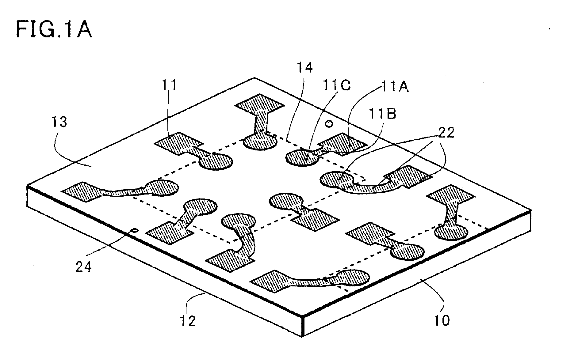

Description
- THE PRESENT INVENTION RELATES A BOARD FOR MANUFACTURING A BGA (Ball Grid Array) and method for manufacturing a semiconductor device using thereof .
- In recent years, use of IC package for portable equipment or small, hi-density mounting equipment progresses, and the conventional IC package and its concept of mounting are largely changing. These details are described in CSP technology, and mounting material and device supporting the technology - special issue of DENSHI ZAIRYO (p.22, Set. 1998).
- Fig. 15 relates to BGA using a
flexible sheet 50 as an inter-poser board, Fig. 15A is a plan view, and Fig. 15B is a section view cut at A-A line. - On the
flexible sheet 50, acopper foil pattern 51 is bonded through adhesive. On theflexible sheet 50, anIC chip 52 is fixed and abonding pat 53 is formed around theIC chip 52 with said copper foil. A solder-ball connecting pad 55 is formed through awiring 54 formed in one body with thebonding pad 53, and on the solder-ball connecting pad 55, a solder-ball is formed. - In Fig. 15A, the
flexible sheet 50 is shown with a solid line of outside, and a rectangle of heavy line is theIC chip 52. As clear from the figure, at inside of thebonding pads 53 formed around theIC chip 52, the solder-ball connecting pads 55 are formed dispersedly in matrix-shape. - At rear side of the solder-
ball connecting pads 55, anopening portion 57 is formed by processing theflexible sheet 50, and the solder-ball 56 is formed through theopening portion 57. - The above-described
flexible sheet 50 is used as a board as same as ceramic board and printed board, and a member processed most thinly among these boards. However the price of the flexible sheet is expensive in comparison with the price of the ceramic board and printed board, and moreover there is a problem that cost of BGA substantially rises including a cost for machining theopening portion 57. - Thin type and lightweight are desired for a semiconductor device mounted for portable equipment and also for the above-described BGA. However considering process forming Cu foil pattern, process mounting the
IC chip 52, andprocess bonding wire 58, theflexible sheet 50 is a member necessarily used for a supporting board, so it is impossible not to use theflexible sheet 50 considering manufacturing process. - Moreover there is a problem that the Cu foil pattern deforms or peels off because the Cu foil pattern is bonded with adhesive on the
flexible sheet 50. As numbers of pad of theIC chip 52 increases year and year, making the Cu foil pattern fine is needed for realization with the BGA. Because of that, bonding area of thewiring 54 and bondingpad 53 decreases, thereby the Cu foil pattern deforms or comes off. - Furthermore there is a problem that manufacturing BGA takes much time because a semiconductor maker informs a flexible sheet maker of designated pattern data, the flexible sheet maker manufactures flexible sheet patterning, and the semiconductor maker purchases the completed flexible sheet. Accordingly it takes for a long time to accomplish a semiconductor device as a product for user. The semiconductor maker can not deliver said BGA to user in short time.
- There is a problem that radiation of heat of the
IC chip 52 is bad because of theflexible sheet 50 interposed between saidCu foil pattern 51 andIC chip 52. - The present invention carried out in the view of the above-mentioned problems is, first, a board for manufacturing BGA, having a first face comprising a flat face and a second face formed facing to said first face, comprising a flat face. On said second face, a first conductive film having substantially same pattern as a bonding pad provided at periphery of a semiconductor element mounting area, a wiring extended to said semiconductor element mounting area in one body with the bonding pad, and an electrode for taking out formed in one body with the wiring is formed. The above formation solves the problem.
- Second, the invention is a flat member having a first face comprising a flat face and a second face formed facing to said first face, comprising a flat face. On said second face, a photo resist having substantially same pattern as a bonding pad formed at periphery of semiconductor element mounting area, a wiring extended to said semiconductor element mounting area in one body with the bonding pad, and an electrode for taking out formed in one body with the wiring is formed. The above formation solves the problem.
- Third, at area corresponding to said bonding pad, a conductive film conductive film is formed, and forming said photo resist so as to cover the film solves the problem.
- By half-etching through conductive film or photo resist formed on the flat board, a conductive pattern supported with the flat member is formed. Therefore semiconductor makers can manufacture for oneself consistently from the flat member to semiconductor device by having an etching facilities.
- As the flat member is used as a supporting board in fixing semiconductor element, electric connection using bonding wire, and sealing process using insulating resin, conventional flexible sheet as a supporting board is not need. Although the bonding pad is thin and exists in island-shape, and the wiring is arranged in unstable state because of its length and thinness, deformation such as bend or peeling is removed because of one body with the flat member.
- By half-etching that pattern of the flat member is not removed from face to back by press or etching and the process is stopped on its way, interval between the conductive patterns can be made narrow so that finer pattern can be formed. Further separation of the pad and the wiring is possible by polishing or etching the back of the flat member after entirely fixing by sealing with an insulating resin, the pattern is arranged in designated position without gap and deformation even in the state of long wiring taken around.
- In case of half-etching the photo resist as a mask, wire bonding is easily realized at the next process by remaining conductive film at the bonding pad.
- Forth, the problem is solved by forming a pattern as substantially same as a guide pin or a guide hole where said guides pin is inserted at side parts of said flat member facing each other so that die mounting of said flat member is carried out in high accuracy at molding.
- Fifth, the problem is solved by said flat member comprises a conductive foil and said conductive film comprises material different from said conductive foil.
- By forming the conductive film, side face of the projection is made bent and further eaves are formed at the conductive film itself. Therefore a bonding pad and wiring being conductive pattern are buried in insulating resin with anchor effect.
- Sixth, the invention is a flat member having a first face comprising a flat face and a second face having a projection formed in desired height and being formed facing to said first face. On said projection, a bonding pad provided at periphery of semiconductor element mounting area, a wiring extended to said semiconductor element mounting area in one body with the bonding pad, and an electrode for taking out provided in one body with the wiring are formed. The above formation solves the problem.
- Seventh, forming a conductive film at surface of said projection solves the problem.
- Eighth, providing a conductive film at least at area corresponding said bonding pad solves the problem
- Ninth, the problem is solved by said flat member comprises a conductive foil and said conductive film comprises material different from said conductive foil.
- In the flat member constructed at the projection, mounting semiconductor, electric connection to the pad, sealing, and so on are possible with facilities of later process of semiconductor maker. Therefore it is possible that a flat member is applied by a material maker and the semiconductor maker manufactures semiconductor device of BGA type.
- Further, the flat member can be transferred more easily without positioning shift and can obtain a good bonding ability.
- As the flat member is used as a supporting board in fixing semiconductor element, electric connection using bonding wire, and sealing process using insulating resin, conventional flexible sheet is removed. Although the bonding pad exists in island-shape, and is arranged in unstable state, deformation such as bend or peeling is removed because of one body with the flat member. Although bend or peeling appears because of long extended wiring, the bonding pad is in one body with the flat member so as to solve the problem.
- Because of, interval between the pads or the conductive patterns is made narrow so that thinner pattern is formed. Further separation of pad, die pad, and the wiring is possible by polishing or etching the back of the flat member after entirely fixing by sealing with insulating resin, the pattern is arranged in designated position without gap.
- Tenth, forming a projection of a pattern as substantially same as a guide pin or guides hole where said guide pin is inserted solves the problem.
- Eleventh, arranging the designated pattern comprising said projection in matrix shape at said flat member solves the problem so that mass production is possible.
- Twelfth, it solves the problem that said flat member comprises Cu, AL, Fe-Ni alloy, layered product of Cu-AL, or layered product of Al-Cu-Al.
- Thirteenth, it solves the problem that a side face of said projection has anchor structure.
- Fourteenth, it solves the problem that said conductive film provides eaves at upper face of said projection.
- Fifteenth, according to using said conductive film made of at least one of Ni, Au, Ag, and Pd, said conductive film has anchor effect, and at the same time wire bonding and die bonding are possible. Sixteenth, the invention is a flat member having a entire flat back face corresponding to resin sealing area and a front face having a projection at an area surrounded with an upper die and a contacting area. The projection has a bonding pad provided at periphery of a semiconductor element mounting area, a wiring extended to said semiconductor element mounting area in one body with the bonding pad, and an electrode for taking out provided in one body with the wiring. It solves the problem that at least area surrounded with contacting area with said upper die constructs sealing space with said surface and said upper die.
- Seventeenth, the invention is a flat member having a entire flat back face corresponding to resin sealing area and a front face having a projection. The projection has a bonding pad provided in an area surrounded with a contacting area to upper die, a wiring extended to said semiconductor element mounting area in one body with the bonding pad, and an electrode for taking out provided in one body with the wiring.
- It solves the problem that the invention has process mounting a semiconductor at said semiconductor mounting area and electrically connecting said bonding pad and said semiconductor element, process mounting said flat member on a die and filling resin into the space constructed with said flat member and said upper die, and process separating said projections respectively removing the flat member exposing at the back face of said resin fill into.
- Eighteenth, the invention is a method for manufacturing a semiconductor device according to
Claim 17 characterized in that all of the back face of said flat member corresponding to said resin-sealing area contacts a lower die. - Nineteenth, it solves the problem that contacting area of said lower die is arranged scattering vacuum suction means.
- Twentieth, said dividing step comprises a step of etching an entire surface of the flat member to a predetermined depth.
- Twenty-First, said dividing step comprises a step of grinding an entire surface of the flat member so as to expose said resin.
- Twenty-Second, said dividing step comprises a step of etching and grinding the flat member so as to expose said resin.
- As the flat member is formed in sheet shape, the back face of the flat member is contacted in all face of the lower die, moreover conductive pattern such as pad and so on does not make any burr thereof at the back face of the flat member because that the conductive pattern is arrange in said sealing space.
- As mentioned, the invention is constructed with conductive pattern, semiconductor element, and insulating resin sealing these and removes a flexible sheet so as to realize thin, light semiconductor device. Moreover by burying a wiring and forming a conductive film on surface of conductive foil, a bonding pat or a wiring having eaves at face thereof is formed and anchor effect appears so as to realize a semiconductor device of BGA type depressing deformation such as bend, lack, and so on of conductive pattern.
-
- [Fig. 1] Fig. 1 is a view describing the flat member of the invention.
- [Fig. 2] Fig. 2 is a view describing the flat member of the invention.
- [Fig. 3] Fig. 3 is a view describing the method for manufacturing the semiconductor device adopting the flat member of the invention.
- [Fig. 4] Fig. 4 is a view describing the method for manufacturing the semiconductor device adopting the flat member of the invention.
- [Fig. 5] Fig. 5 is a view describing the flat member of the invention.
- [Fig. 6] Fig. 6 is a view describing the flat member of the invention.
- [Fig. 7] Fig. 7 is a view describing the method for manufacturing the semiconductor device adopting the flat member of the invention.
- [Fig. 8] Fig. 8 is a view describing the method for manufacturing the semiconductor device adopting the flat member of the invention.
- [Fig. 9] Fig. 9 is a view describing the method for manufacturing the semiconductor device adopting the flat member of the invention.
- [Fig. 10] Fig. 10 is a view describing the method for manufacturing the semiconductor device adopting the flat member of the invention.
- [Fig. 11] Fig. 11 is a view showing the flat member adopted as a lead frame.
- [Fig. 12] Fig. 12 is a view describing the method for manufacturing the semiconductor device adopting the flat member of the invention.
- [Fig. 13] Fig. 13 is a view describing the method for manufacturing the semiconductor device adopting the flat member of the invention.
- [Fig. 14] Fig. 14 is a view describing the method for manufacturing the semiconductor device adopting the flat member of the invention.
- [Fig. 15]
Fig. 15 is a view describing the conventional
semiconductor device of BGA structure.
- 10
- Flat member
- 11
- Conductive film
- 12
- First face
- 13
- Second face
- 14
- Semiconductor element mounting area
- 15
- Semiconductor element
- 16
- First bonding pad
- 17
- Second bonding pad
- 18
- Wiring
- 19
- Electrode for taking out
- 20
- Bonding wire
- 21
- Insulating resin
- 22
- Conductive pattern
- 23
- Semiconductor device
-
- The invention relates a semiconductor device arranged bonding pads at periphery of a semiconductor chip and electrodes for taking out in matrix-shape using wirings of one body with the bonding pads. Although it is generally called BGA that a solder ball is attached at the electrode for taking out, it is called a semiconductor device of BGA construction here including fixing by usual soldering.
- Fig. 1A shows a flat member which is advanced in effect than BGA so that thinner package is realized, than that of the package using the conventional flexible sheet.
- In the
flat member 10, a conductive pattern printed on the conventional flexible sheet in BGA is formed with aconductive film 11. - That is, the
flat member 10 has afirst face 12 comprising flat face and asecond face 13 comprising flat face provide facing saidfirst face 12. On saidsecond face 13, a firstconductive film 11A as substantially same pattern as asecond bonding pad 17 is formed at periphery of asemiconductor mounting area 14. The firstconductive film 11A is provided corresponding to afirst bonding pad 16 on asemiconductor element 15 shown in Fig. 3 and is formed in substantially same pattern as thesecond bonding pad 17. Awiring 18 provide in one body with the above-mentionedsecond bonding pad 17, a secondconductive film 11B substantially same pattern with anelectrode 19 for taking out, and a thirdconductive film 11C are formed. Theseconductive films 11A to 11C may comprise in same material or not. However for the conductive film s 11A to 11C, the material available for etching resist mask is selected as clear in later mentioned method for manufacturing, and for surface of theconductive film 11A, material in whichbonding wire 20 comprising Au or Al is in use by ball bonding method or ultrasonic bonding method is selected. - As clear in description of Fig. 13, material in which brazing filler metal and conductive paste are fixed is selected for the
conductive film 11A in case of using a facedown-type element (SMD) as thesemiconductor element 15. - On the
flat member 10, an etching resist mask MSK such as photo resist and so on may be formed instead of saidconductive film 11 as Fig. 1B. In this case, aconductive film 20 is formed at part corresponding to at least thesecond bonding pad 17 so that bonding using bonding wire or facedown bonding is possible, and all patterns including the conductive film is covered by photo resist MSK. - Characteristic of the invention is in said
flat member 10. As clear in later description, theflat member 10 is half-etched through theconductive film 11 or photo resist MSK thereof, thesemiconductor 15 is mounted thereon, and is sealed by insulatingresin 21. Theflat member 10 exposing at the back face of the insulatingresin 21 is processed by etching, grinding or polishing etc. tillconductive pad 22 comprising the second bonding pad, thewiring 18, and theelectrode 19 for taking out is separated. By adopting the method for manufacturing, the semiconductor device is constructed by three materials; thesemiconductor element 15, aconductive pattern 22, the insulatingresin 21 burying thesemiconductor element 15 and theconductive pattern 22. Theflat member 10 is functioned as asemiconductor device 23 of BGA finally. - The biggest characteristic of the structure is that the
conductive film 11 or etching-resist mask MSK is formed on surface of theflat member 10 so as to half-etch. - Generally in etching, lateral direction etching advances with advance of longitudinal direction etching. For example in case of isotropic etching, this phenomenon appears so that depth of longitudinal direction etching and length of lateral direction etching are substantially same. In anisotropic etching, said lateral direction etching is carried out though length of lateral direction etching is very shorter than in case of isotropic etching.
- For example in the semiconductor device with BGA structure shown in Fig. 15, in case of forming
conductive patterns 53 to 55 on aflexible sheet 50, it is necessary to remove the patterns so as to pass through from face to back of bonded Cu foil. However interval of conductive patterns is etched even to lateral direction, interval of theconductive pattern 22 and adjacent conductive pattern thereto can not made smaller than certain limit value because of correlation with thickness of Cu foil so that forming of fine pattern is difficult. Even in case of realizing semiconductor device of BGA construction adopting etching-type lead frame, similar phenomenon appears. Even in case of removing the lead frame by press, thickness of the lead frame becomes minimum interval between leads of the lead frame so that fine pattern has limit. - However by forming the
conductive film 11 or the etching-resist mask MSK and then half-etching in depth suitable for fine pattern forming, etching quantity of lateral direction is depressed so that finerconductive pattern 22 is realized. - When
conductive film 11 such as Ni, Ag, Au, Pd, and so on as a conductive film is formed on theflat member 10 of thick ness of 2 oz. (70 µm) and the film is etched till entirely passing through using a mask therefor, interval of the conductive pattern is substantially 70 µm at the narrowest case. However by using theconductive film 11 as etching-resist mask and by etching theflat member 10 till depth of 35 µm, interval of the conductive patterns can be processed till depth of 35 µm. That is, two times mounting efficiency is realized. In this fine pattern, the finer pattern is possible as the shallower depth of half-etching to theflat member 10. - In the
flat member 10 according to the invention, wet etching is desirable considering etching facilities, mass-productivity, and manufacturing cost. However wet etching is non-anisotropic and etching of lateral direction is comparatively great in quantity. Therefore half-etching using theconductive film 11 and the etching-resist mask MSK is superior for finerconductive pattern 22. - In the
flat member 10 of the invention, theconductive pattern 22 does not slip and bend as long as theflat member 10 is fixed because the half-etchedconductive pattern 22 is in one body with theflat member 10. The flat member has characteristic that bonding to thesecond bonding pad 17 is stable. - Although it is need to support the conductive pattern with hanging lead in the semiconductor device with BGA structure forming the above-mentioned lead frame, it is not need in the invention. Therefore the
conductive pattern 22 is arranged at any position without considering crossing the hanging lead so that design of theconductive pattern 22 becomes easy. - It is convenient to provide a
guide hole 24 at the time of mounting theflat member 10 on a die. - The
guide hole 24 may be opened before molding by drill, punching, or etching along the pattern patterned in a round shape at corresponding position with substantially same shape as a guide pin by conductive film or photo resist. The guide hole may be previously opened. Inserting the guide pin of the die into theguide hole 24 makes molding of high position accuracy possible. - As above-mentioned, the
conductive pattern 22 appears by half-etching through theconductive film 11 or the etching-resist mask MSK, and this is possible to adopt as the conventional flexible sheet or the conventional lead frame. - A semiconductor maker generally has'plants for front process and back process (back-end process) separately, and in the back process molding adopting the
flat member 10, generally etching facilities are not set up. Therefore the semiconductor maker can manufacture asemiconductor device 23 of BGA construction using the flat member by setting up film-making facilities of theconductive film 11 and etching facilities and by purchasing theflat member 10 where theconductive film 11 or the etching-resist mask MSK is formed from a metal material maker manufacturing lead frame. - The
conductive pattern 22 may be a shape such as wiring having substantially constant width from an end to other end as shown in Fig. 1C. Although thepad 11A and theelectrode 11C of Fig. 1A and Fig. 1B are rectangular and circle respectively, the shape is optional. - The
flat member 30 is half-etched through saidconductive film 11 or etching-resist mask MSK, and aconductive pattern 22 is formed in projection shape. - That is, a
flat member 30 has afirst face 12 comprising a flat face and asecond face 13 having aprojection 31 formed in desired height and being formed facing to saidfirst face 12, and saidprojection 31 comprises asecond bonding pad 17 provided at periphery of semiconductorelement mounting area 14, awiring 18 of one body with the second bonding pad, and anelectrode 19 for taking out provided in one body with the wiring. - The
flat member 30 is substantially as same construction and same effect of theflat member 10 described in the first mode for carrying out. Difference is a point that the conductive pattern is half-etched. - Therefore a half-etching process will be described here. That is, a semiconductor maker, particularly in back process, does not have plating facilities of a
flat member 10 comprising Cu and lithography facilities such as etching and so on. Therefore by purchasing theflat member 30 having theconductive pattern 22 comprising the projection using half-etching, theflat member 30 can be handled as same as the conventional lead frame so that it is possible to manufacture thesemiconductor device 23 of BGA construction with existing facilities of the back process. - The
conductive pattern 22 comprising the projection can be made by pressing theflat member 10. In case of the press, it is need to make thefirst face 12 flat if necessary by polishing or grinding because thefirst face 12 projects. - Third mode for carrying out describing a method for manufacturing semiconductor device adopting the flat member
- Manufacturing the
semiconductor device 23 with BGA structure using the above-mentionedflat member flat member 10 of Fig. 1A half-etched, and Fig. 2B shows theflat member 10 of Fig. 1B half-etched. Fig. 2C shows theflat member 10 of Fig. 1C half-etched. After Fig. 3, the flat member is described assuming that it is manufactured like Fig. 1A and Fig. 2A. - First a
flat member 10 is provided. In theflat member 10, thefirst face 12 and thesecond face 13 are flat, and an etching-resist mask MSK of aconductive film 11 or a photo resist shaping into aconductive patternconductive pattern 22 are formed on thesecond face 13. In Fig. 1A, theconductive film 11 is formed on all face of theconductive pattern 22, which is hatched with diagonal lines. In Fig. 1B, a photo resist MSK is used instead of theconductive film 11 and covers aconductive film 11A formed at part corresponding to at least asecond bonding pad 17. The photo resist MSK is hatched with dots. (Refer Fig. 1 about the above.) - Next the
flat member 10 is half-etched through saidconductive film 11 or the photo resist MSK. Depth of etching is shallower than thickness of theflat member 10. The shallower depth of etching, the forming of fine pattern is possible. - By half-etching, the
conductive pattern 22 appears in projection shape on thesecond face 13 of theflat member 10 as Fig. 2. Theflat member 10 may be made of Cu material, Al material, Fe-Ni alloy material, layered product of Cu-Al, or layered product of Al-Cu-Al. Particularly layered product of Al-Cu-Al can prevent bend generating by difference of coefficient of thermal expansion. - For example, by purchasing the
flat member 10 of Fig. 1 from a frame maker if a semiconductor maker has etching facilities at the back process, and by purchasing theflat member 30 which the conductive pattern thereof is half-etched in projection shape if the semiconductor maker does not have etching facilities, the process can be moved to next process. (Refer Fig. 2 about the above.) - Next, a
semiconductor element 15 is fixed at asemiconductor mounting area 14, and afirst bonding pad 16 of thesemiconductor element 15 and asecond bonding pad 17 are electrically connected. In the figure, abonding wire 20 is used for connecting means because thesemiconductor element 15 is mounted in face-up type. In case of facedown type mounting, solder bump, brazing material such as solder ball, conductive paste such as Ag and Au, conductive ball, or anisotropic conductive resin is considered for connecting means. - In this bonding, the
second bonding pad 17 is in one body with theflat member 30, moreover the back face of theflat member 30 is flat. Because of that, theflat member 30 is face-contacted to a table of a bonding machine. Therefore by entirely fixing theflat member 30 on the bonding table, without causing thesecond bonding pad 17 deviated, bonding energy can be transferred to thebonding wire 20 and thesecond bonding pad 17 so that connecting strength of thebonding wire 20 is improved. Fixing of bonding table is possible by providing a plural of vacuum suction holes V at all the table like Fig. 9 for example. - For fixing the
semiconductor element 15 and theflat member 30, insulatingadhesive 32 is used, and considering radiation, filler such as Si oxide, Al oxide, and so on may be mixed the insulatingadhesive 32. - Then an insulating
resin 21 is formed so as to cover said conductive pattern, thesemiconductor element 57, and connecting means. - For example in case of sealing using a die, a
guide hole 24 is provided on the flat board, and a guide pin of the die is inserted into the hole. Because thefirst face 12 of theflat member 30 is flat, face of lower die is formed flat. Any of thermal plasticity and thermohardening is used for the insulatingresin 21. - The molding is realized by transfer molding, injection molding, dipping, and painting realize. As resin material, thermohardening resin such as epoxy resin etc. is used for transfer molding, and thermal plasticity resin such as liquid crystal polymer, polyphenylenesulfide, and so on is used for injection molding.
- In the mode for carrying out, thickness of insulating
resin 21 is adjusted so that upper part from top portion of thebonding wire 20, is about 100 µm, is covered. This thickness is possible to make thick or thin considering strength of thesemiconductor device 23. - In filling, position shift of the
conductive pattern 22 as long as theflat member 30 does not shift because the conductive pattern is formed in one body with theflat member 30. Fixing the lower die and the back face of theflat member 30 is realized by vacuum suction. A depressing pin provided at the die may be used. - As the above, in the insulating
resin 21, theconductive pattern 22 formed as theprojection 31 and thesemiconductor element 15 are buried, and theflat member 30 of lower part than theprojection 31 exposes from the back face of the insulating resin. (Refer Fig. 3 about the above.) - Next, the
flat member 30 exposing at the back face of said insulatingresin 21 is removed, and theconductive pattern 22 is separated individually. - A various methods are considered for the separating process, that is, the back face may be removed by any of etching and polishing or grinding. Both of them are available. For example, there is a problem that scraped chip of the
flat member 30 and burr-shape metal extended thin to outside encroaches on the insulatingresin 21 so as to be thinner. Because of that, grinding is stopped before the insulatingresin 21 exposes, after that, by separating theconductive pattern 22 by etching, the conductive pattern is formed without encroaching of metal of theflat member 30 on the insulatingresin 21 positioned between theconductive patterns 22. That prevents a short between theconductive patterns 22 of fine interval. - In half-etching, dispersion of thickness appears on the insulating
resin 21 between theconductive patterns 22 by dispersion of etching depth. After separating theconductive patterns 22 individually by etching method, Grinding can be conducted so as to be a predetermined thickness, therefore a package having a certain thickness can be formed. - In case that a plural of one unit being the
semiconductor device 23 are formed, there is a dicing process asindividual semiconductor device 23 after the separating process. The dicing line is shown with thick dotted line. - Although the semiconductor devices are separated individually using the dicing equipment, chocolate breaking, pressing, or cutting is possible.
- The
conductive pattern 22 exposing at the back face may be exposed at part corresponding to anelectrode 19 for taking out as Fig. 4B. For the exposedelectrode 19 for taking out, one of the connecting means such as fitting of conductive ball such as solder ball, covering of conductive paste such as brazing material such as solder or conductive paste such as Ag paste, anisotropic conductive resin is selected. - In Fig. 4C, etching is carried out through photo resist formed on the exposed
electrode 19 for taking out, and the exposedelectrode 19 for taking out is made projection shape. A conductive resin R is covered so that the exposedelectrode 19 for taking out exposes. - By coating the insulting resin R at the back face as Fig. 4B and Fig. 4C,wiring of mounting board side can be passed at the lower layer. (Refer Fig. 4 about the above.) By the above-mentioned method of manufacturing, three elements of a plural of
conductive patterns 22, thesemiconductor element 15, and insulatingresin 21 realizes a light, thin, short, small semiconductor device of BGA structure. - Next, effect generating by the above-mentioned method for manufacturing.
- First, a flexible sheet used as a supporting board is removed because the
conductive pattern 22 is half-etched and supported in one body with theflat member 30. - Second, making the
conductive pattern 22 fine is possible because theconductive pattern 22 which is half-etched and has a projection is formed on theflat member 30. Therefore width of theconductive pattern 22 and interval between theconductive patterns 22 can be narrow so that smaller package in plane size is formed. - Third, because of construction of said three elements, the semiconductor device consists of the least necessary elements, and useless material is removed to the utmost so that a thin
type semiconductor device 23 which is depressed largely in cost is realized. - Fourth, because the
second bonding pad 17, thewiring 18 and theelectrode 19 for taking out are formed in projection by half-etching, and separating individually is carried out after sealing, tie bar and hanging lead(support bar) used for lead frame are not need so that pattern design becomes easy. - Although only one semiconductor element is mounted in the semiconductor device of the BGA structure, a plural of semiconductor elements may be mounted.
- Fig. 5 shows a
flat member 10 where aconductive film 11 forms aconductive pattern 22 as same as the first mode for carrying out. An etching resist mask such as photo resist may be formed instead of theconductive film 11. In this case, a conductive film is formed at part corresponding to a bonding pad, and a photo resist pattern is formed so as to cover the conductive film. - The pattern shaping up the pattern of Fig. 1 is shown in Fig. 5. Concretely,
pattern units 34 where conductive pattern surrounded by dotted line is one semiconductor are formed in matrix shape, and die contactingarea 35 is formed in ring shape with designated width as surrounding the pattern units. That is, pattern of Fig. 5 shows the conductive pattern formed in one cavity. - At inside of the
die contacting area 35, alignment marks 36 and 37 are provided. A line connectingalignment marks - Moreover at outside of said die-contacting
area 35; afirst pattern 38 and asecond pattern 39 for forming a guide hole are formed. The cross of thesecond pattern 39 is a centering mark when forming the guide hole by drill. A guide hole same shape as the first pattern may be provided previously without forming the pattern. - AS above-mentioned, characteristic and effect of the mode for carrying out are omitted because these are same as the first mode for carrying out except the line mark of dicing line and the
die contacting area 35. - The
flat member 30 has a shape shown in Fig. 6, and has aprojection 31 half-etched through the etching-resist mask of theconductive film 11 or the photo resist shown in the fourth mode for carrying out. Afirst alignment mark 38 and asecond alignment mark 39 may be formed in projection shape by half-etching. - The
flat member 30 is handled similarly as the conventional lead frame, SIP, DIP, QIP, and so on for example. - That is, a
flat member 30 has afirst face 12 comprising a flat face and asecond face 13 having aprojection 31 formed in desired height and being formed facing to saidfirst face 12, and saidprojection 31 comprises asecond bonding pad 17 provided at periphery of semiconductor element mounting area, awiring 18 of one body with thesecond bonding pad 17, and anelectrode 19 for taking out 19 provided in one body with thewiring 18. - The
flat member 30 is in the state that each pattern is half-etched, and it is possible to fix the semiconductor element, to connect electrically, and to seal so that manufacturing with existing facilities of the back process is possible. - As the effect is described in the first mode for carrying out and the fourth mode for carrying out, it is omitted here.
- Six mode for carrying out describing a method for manufacturing a semiconductor device
- Next, a method for manufacturing the semiconductor device is described referring Fig. 5 to Fig. 11.
- First, a
flat member 10 is provided as Fig. 5. Material for theflat member 10 is selected considering adhesion of brazing material, characteristic of bonding and plating characteristic. They are a conductive foil which is Cu as main material, a conductive foil which is Al as main material, a conductive foil of sheet shape comprising alloy of Fe-Ni, layered product of Cu-Al, and layered product of Al-Cu-Al. On the surface of theflat member 10, asecond bonding pad 17, awiring 18, anelectrode 19 for taking out, adie contacting area 35, alignment marks 36 and 37,patterns conductive film 11 or a photo resist. - It is desired that thickness of the conductive foil used for the
flat member 10 is about 10 µm to 300 µm, here Cu foil of 70 µm (2 oz.) is used. However fundamentally the thickness may be more than 300µm or less than 10 µm. (Refer to Fig. 5 about the above.) - Next, the
flat member 10 is selectively removed except area providing thesecond bonding pad 17, thewiring 18, theelectrode 19 for taking out, thedie contacting area 35, the alignment marks 36 and 37, andpatterns flat member 10. - Here the
conductive film 11 or the photo resist is used for an etching-resist mask, and saidisolation groove 40 is formed shallower than thickness of theflat member 10. - In the method for manufacturing, the flat member is etched non-anisotropicaly by wet etching or dry etching, and has characteristic that the side thereof has coarse face and made bend.
- In case of the wet etching, ferric chloride or cupric chloride is generally used for etchant, said conductive foil is dipped into the etchant or the etchant is showed.
- Especially just under the
conductive film 11 or photo resist being etching mask, etching of lateral direction is hard to advance and deeper part than the etching mask is etched to lateral direction. Because of that, the upper direction of the position goes from one side of theisolation groove 40, the smaller opening diameter of the opening corresponding to the position becomes, so that the opening has reverse-tapered structure having anchor structure. By using showering, etching is advance to depth direction and etching to lateral direction is depressed so that the anchor structure remarkably appears. - In the case of dry etching, both of anisotropic and non-anisotropic etchings can be used. Although it is said impossible to remove Cu by reactive ion etching nowadays, Cu is removed by spattering. Depending on the condition of the spattering, both of anisotropic and non anisotropic etchings are possible.
- Material for the conductive film is Ni, Ag, Au, Pt, or the like. These corrosive resistant conductive film s have characteristic that they are used alone for a bonding pad.
- For example, thin Au wire can be bonded to the conductive film of Ag and Au. Ni makes ultrasonic bonding with Al wire possible. Therefore, these conductive film s have a merit that they are used alone for a bonding pad.
- Of course here, anisotropic etching may form the projection. (Refer Fig. 6 about the above.)
- Next, there is a process mounting the
semiconductor element 15 on the semiconductorelement mounting area 14 as Fig. 7. - The
semiconductor element 15 is a transistor, diode, IC chip, and the like. CSP of wafer-scale type and SMD (semiconductor element of facedown type) of BGA and the like can be mounted though thickness of them becomes thick. - Here a bare IC chip is fixed by insulating
adhesive 32, and afirst bonding pad 16 on the IC chip and asecond bonding pad 17 are connected through abonding wire 20 fixed by ball bonding using thermocompression bonding or wedge bonding using ultrasonic wave. - The
bonding pad 17 shown in the figure is in one body with theflat member 30 though the size thereof is very small. Therefore energy of a bonding tool can transfer to thebonding pad 17 so that bonding ability is improved. There is a case to pull-cut a bonding wire at cutting the bonding wire after bonding. Because that thesecond bonding pad 17 is in one body with theflat member 30 in this case, phenomena that thebonding pad 17 rises is removed and pull-cutting ability is improved. (Refer Fig. 7 about the above.) - Moreover there is a process of applying an insulating
resin 21 in anisolation groove 40 . This is realized by transfer molding, injection molding, dipping, or painting. As resin material, thermohardening resin such as epoxy resin etc. is used for transfer molding, and thermal plasticity resin such as liquid crystal polymer, polyphenylenesulfide, and so on is used for injection molding. - In the mode for carrying out, thickness of insulating
resin 21 is adjusted so that upper part from top portion of thebonding wire 20, about 100 µm, is covered. This thickness is possible to make thick or thin considering strength of thesemiconductor device 23. - Characteristic of the process is that the
flat member 30 functions as a supporting board till the insulatingresin 21 is covered and hardened. Although a supporting board of a flexible sheet is need in the conventional BGA, the invention does not need. - Moreover, because the insulating
resin 21 is filled in theisolation groove 40 having bending structure, anchor effect appears at this part so that saidconductive pattern 22 is hard to peel off from the insulatingresin 21. - Potting silicon resin and the like is useful in order to protect connecting portion the semiconductor chip and the bonding wire for example before covering the insulating
resin 21. - Fig. 9 shows the molding method. Fig. 9A is a section view showing the state that the insulating
resin 21 is filled into acavity 101 in adie 100. It is clear that the back face of theflat member 30 contacts alower die 100A andupper die 100B contacts at a die contacting area. The symbol V is a vacuum suction hole. Fig. 9B shows the state that theflat member 30 is mounted on thelower die 100A.Symbol 102 is a guide pin attached at thelower die 100A, and the guide pin appears through a guide hole opened at theflat member 30. - Fig. 9C is a view describing relation of a
cavity 101, arunner 103, and apot 104 formed at the die. As shown in the figure, the die is designed so thatseveral cavities 101 are arranged to lateral direction and a lot of semiconductor devices are taken from one frame.Symbol 105 shown with dotted line shows arranging area of the flat member, and theflat member 106 like Fig. 11 for example is mounted with handling similar as the conventional lead frame. Theflat member 30 as shown in Fig. 6 is formed by using the die where plural cavities and so on are made in one body. The semiconductor device manufactured with the flat member itself is small in size, and is possible to take a lot of devices in one cavity and to mass-product, so as to decrease manufacturing cost. (Refer to Fig. 8 and Fig. 9 about the above.) - Next, there is a process removing the
flat member 30 exposing at the back face of the insulatingresin 21 and separating theconductive pattern 22. - Fig. 10A is a plan view showing separating line, and Fig. 10B shows that the back face of the insulating
resin 21 and thesecond bonding pad 17, or the back face of the insulatingresin 21 andwiring 18 and theelectrode 19 for taking out, are fit. This is possible by grinding off using polisher or grinder till theisolation groove 40 exposes . Only part needing electrical connection may be exposed from an insulating film such as solder resist and the like. - In Fig. 10C, a projection 111 is formed at
other end 110 of theelectrode 19 for taking out, by stopping the polishing on the way. This is possible by forming photo resist at part corresponding to the projection 111 and by etching part except this. The insulating film R is formed so that the projection 111 exposes. This process can prevent a short to conductive member of mounting board side passing under thesemiconductor element 15. - Finally, the semiconductor device completes by arranging the molding member on a dicing table, adjusting position of a blade referring the alignment marks 36 and 37, and dicing along the line shown with the dotted line.
- Seventh mode for carrying out describing a method for manufacturing a semiconductor device
- Next, Fig. 12 to Fig. 14 show mounting a
semiconductor element 150 of facedown type on aflat member 151 and manufacturing a semiconductor device of BGA structure. - Although a
conductive pattern 22 is extended outer from semiconductor element mounting area by using abonding wire 20, it is possible to make less or to remove the projection by adopting the facedown type. Although thickness of the package becomes thick because the top of thebonding wire 20 becomes high, thin type is possible by adopting the facedown type. - For the semiconductor element of facedown type, a
solder ball 152, or bump of solder or Au instead of the solder ball is used. - In case of fixing the
semiconductor element 150 with brazing material such as solder, it is not need to form the conductive film like the bonding pad because an electrode for taking out 153 consists of Cu as main material. However it needs for generating anchor effect making eaves. - As method for manufacturing is similar as said mode for carrying out, it is described simply.
- A
flat member 151 is providing as shown in Fig. 12, thesolder ball 152 of thesemiconductor element 150 is fixed on theflat member 151. - Next, the flat member is sealed using an insulating
resin 154 as shown in Fig. 13. - Finally, the semiconductor device completes by separating the conductive pattern removing the
flat member 151 positioning at the back face of the insulatingresin 154 and by dicing along the line shown with the dotted line as shown in Fig. 14. - A part corresponding to the electrode for taking our may be exposed covering the insulating resin R on the back face of the package as Fig. 10B and Fig. 10C.
- By covering a conductive film which is small in etching rate on the flat member and half-etching through the conductive film, eaves and bending structure are realized so as to have anchor effect. This is applicable for all modes for carrying out.
- The method is suitable because Cu and Ni formed on the Cu are etched at the same time by ferric chloride or cupric chloride and eaves of Ni is formed by difference of etching rate.
- As clear from the above description, the flat member of the invention has the structure half-etching the conductive pattern through the conductive film or the photo resist. Moreover the flat member can construct as the conductive pattern by stopping press or etching on the way without removing the flat member from front to back. The construction adopting the half-etching can make interval of the conductive pattern narrow so that the pattern for finer semiconductor device of BGA construction is possible. As the second bonding pad, the wiring, and the electrode for taking out are constructed in one body, deformation or bend is depressed. Moreover separating the conductive pattern is possible by polishing or etching the back face of the flat member after fixing entirely sealing the insulating resin so that the conductive pattern can be arranged at the designated position without position shift. Further the wiring necessary for the semiconductor device of BGA construction can be arranged without any deformation.
- Arranging all of the conductive pattern area in the resin sealing area can remove burr generating from the conventional lead frame.
- Forming the same pattern as the guide pin can open as the guide hole at sealing with the insulating resin. As the flat member is set on the guide pin of the die for sealing, resin sealing of high position accuracy is possible.
- Constructing the flat member with Cu as main material and constructing the conductive film with Ni, Ag, Au or Pd can use the conductive film as an etching mask. Further when the flat member is half-etched, side thereof provides bending structure and eaves by the conductive film is formed at surface of the conductive pattern, and the flat member has the structure having anchor effect. Therefore removing and bend of the conductive pattern positioning at the back face of the insulating resin are prevented.
- The semiconductor device manufactured at the flat member consists of the least necessary elements of the semiconductor element, the conductive pattern, and the insulating resin so that the semiconductor device is useful for resources. Therefore the semiconductor device extremely decreasing cost is realized. As the supporting board such as a flexible board is not used, heat resistance of the supporting board is removed so that radiation ability is improved. By making thickness of film of the insulating resin and thickness of the conductive foil optimum, the small, thin, and light semiconductor is realized.
- Exposing from the insulating resin, the back face of the conductive pattern can instantly connect to outside so that process of through-hole such as the flexible sheet of the conventional structure is not need.
- The semiconductor device has a structure having flat surface where the surface of the isolation groove and the surface of the conductive pattern are substantially same, and correction of shift of the electrode for taking out is extremely easy because the semiconductor device itself is moved just horizontally even if mounting the narrow pitch GFP on the mounting board.
- Side face of the conductive pattern has bending structure, and eaves are formed at the front face. Therefore it is possible to generate anchor effect and to prevent bend and removing.
- The flat member supports the entire device till the insulating resin is covered, and at separation and dicing of the conductive pattern, the insulating becomes a supporting board. Therefore the supporting board described in the prior art is removed, and the invention has a merit that the device is made low in cost.
Claims (22)
- A board for manufacturing a BGA, comprising a first face of a flat face and a second face of a flat face facing to said first face,
wherein said second face forms a first conductive film having substantially same pattern as a bonding pad provided at periphery of semiconductor element mounting area, a wiring extended to said semiconductor element mounting area integrated with the bonding pad, and an electrode for taking out formed in one body with the wiring. - A board for manufacturing a BGA, comprising a first face of a flat face and a second face of a flat face facing to said first face,
wherein said second face forms a photo resist having substantially same pattern as a bonding pad provided at periphery of semiconductor element mounting area, a wiring extended to said semiconductor element mounting area integrated with the bonding pad, and an electrode for taking out formed in one body with the wiring. - A board for manufacturing a BGA according to Claim 2, wherein a conductive film is provided at area corresponding to said bonding pad and said photo resist is formed so as to cover the conductive film .
- A board for manufacturing a BGA according to Claim 1, wherein a substantially same pattern as a guide pin or a guide hole where said guides pin is inserted is formed at side parts of said flat member facing each other.
- A board for manufacturing a BGA according to Claim 1, wherein said flat member comprises a conductive foil and said conductive film comprises material different from said conductive foil.
- Aboard for manufacturing a BGA comprising a first face of a flat face and a second face having a projection formed in desired height and facing to said first face,
wherein said projection is formed in an area corresponding to a bonding pad provided at periphery of a semiconductor element mounting area, a wiring extended to said semiconductor element mounting area integrated with the bonding pad, and an electrode integrated with the wiring. - A board for manufacturing a BGA according to Claim 6, wherein a conductive film is formed on surface of said projection.
- A board for manufacturing a BGA according to Claim 7, wherein a conductive film is formed on at least an area corresponding to said bonding pad.
- A board for manufacturing a BGA according to Claim 6 , wherein said flat member comprises a conductive foil and said conductive film comprises material different from said conductive foil.
- A board for manufacturing a BGA according to Claim 6, wherein a substantially same pattern as a guide pin or a guide hole where said guides pin is inserted is formed at side parts of said flat member facing each other.
- A board for manufacturing a BGA according to Claim 6, wherein a pattern of said projection is formed in a matrix manner.
- A board for manufacturing a BGA according to Claim 6, wherein said flat member comprises Cu, Al, Fe-Ni alloy, layered product of Cu-Al, or layered product of Al-Cu-Al.
- A board for manufacturing a BGA according to Claim 6, characterized in that side face of said projection has an anchor construction.
- A board for manufacturing a BGA according to Claim 6, characterized in that said conductive film constructs eaves at an upper face of said projection.
- A board for manufacturing a BGA according to Claim 14, wherein said conductive film is made of anyone of Ni, Au, Ag, and Pd.
- A board for manufacturing a BGA having a entire flat back face corresponding to a resin sealing area and a front face having designated thickness from said back face formed in sheet shape, the front face forming a projection at an area surrounded with a contacting area to an upper die, the projection having a bonding pad provided at periphery of a semiconductor element mounting area, a wiring extended to said semiconductor element mounting area in one body with the bonding pad, and an electrode for taking out provided in one body with the wiring,
wherein at least an area surrounded with contacting area to said upper die constructs a sealing space with said front face and said upper die. - A method of manufacturing a semiconductor device comprising steps of:preparing a board comprising a entire flat back face corresponding to a resin sealing area and a front face formed in sheet shape having designated thickness from said back face, the front face forming a projection, the projection having a bonding pad provided at an area surrounded with a contacting area to an upper die, a wiring extended to said semiconductor element mounting area integrated with the bonding pad, and an electrode for taking out provided in one body with the wiring;mounting each of semiconductor chips at said semiconductor element mounting area to electrically connectsaid semiconductor element to said bonding pad ;placing said board on a die;filling resin into the space constructed with said flat member and said upper die; anddividing into a plurality of devices so that said projections are separated respectively by removing the flat member exposed at the back face of said resin filled into.
- A method for manufacturing a semiconductor device according to Claim 17, wherein the entire back face of said flat member corresponding to said resin-sealing area contacts a lower die.
- A method for manufacturing a semiconductor device according to Claim 18, wherein that vacuum suction means is arranged separately at a contacting area of said lower die.
- A method for manufacturing a semiconductor device according to Claim 17, wherein said dividing step comprises a step of etching an entire surface of the flat member to a predetermined depth.
- A method for manufacturing a semiconductor device according to Claim 17, wherein said dividing step comprises a step of grinding an entire surface of the flat member so as to expose said resin.
- A method for manufacturing a semiconductor device according to Claim 17, wherein said dividing step comprises a step of etching and a step of grinding of the flat member so as to expose said resin.
Applications Claiming Priority (2)
| Application Number | Priority Date | Filing Date | Title |
|---|---|---|---|
| JP2000152429 | 2000-05-24 | ||
| JP2000152429A JP3883784B2 (en) | 2000-05-24 | 2000-05-24 | Plate-shaped body and method for manufacturing semiconductor device |
Publications (2)
| Publication Number | Publication Date |
|---|---|
| EP1160858A2 true EP1160858A2 (en) | 2001-12-05 |
| EP1160858A3 EP1160858A3 (en) | 2004-04-28 |
Family
ID=18657855
Family Applications (1)
| Application Number | Title | Priority Date | Filing Date |
|---|---|---|---|
| EP01302530A Withdrawn EP1160858A3 (en) | 2000-05-24 | 2001-03-20 | A board for manufacturing a bga and method of manufacturing semiconductor device using thereof |
Country Status (6)
| Country | Link |
|---|---|
| US (2) | US6975022B2 (en) |
| EP (1) | EP1160858A3 (en) |
| JP (1) | JP3883784B2 (en) |
| KR (1) | KR100404062B1 (en) |
| CN (1) | CN1173400C (en) |
| TW (1) | TWI272707B (en) |
Cited By (6)
| Publication number | Priority date | Publication date | Assignee | Title |
|---|---|---|---|---|
| WO2003086037A1 (en) * | 2002-04-11 | 2003-10-16 | Koninklijke Philips Electronics N.V. | Method of manufacturing an electronic device |
| WO2003085731A1 (en) | 2002-04-11 | 2003-10-16 | Koninklijke Philips Electronics N.V. | Semiconductor device and method of manufacturing same |
| EP1659628A1 (en) * | 2004-11-23 | 2006-05-24 | Optium Care International Tech. Inc. | High lead density electronic device |
| WO2008122959A2 (en) * | 2007-04-10 | 2008-10-16 | Nxp B.V. | Package, method of manufacturing a package and frame |
| WO2009059883A1 (en) * | 2007-11-08 | 2009-05-14 | Cambridge Silicon Radio Limited | Chip packaging |
| GB2508633A (en) * | 2012-11-29 | 2014-06-11 | Cambridge Silicon Radio Ltd | Die package |
Families Citing this family (60)
| Publication number | Priority date | Publication date | Assignee | Title |
|---|---|---|---|---|
| JP4761662B2 (en) * | 2001-07-17 | 2011-08-31 | 三洋電機株式会社 | Circuit device manufacturing method |
| US7001798B2 (en) * | 2001-11-14 | 2006-02-21 | Oki Electric Industry Co., Ltd. | Method of manufacturing semiconductor device |
| JP2003243435A (en) | 2002-02-14 | 2003-08-29 | Hitachi Ltd | Manufacturing method for semiconductor integrated circuit apparatus |
| US8236612B2 (en) * | 2002-04-29 | 2012-08-07 | Unisem (Mauritius) Holdings Limited | Partially patterned lead frames and methods of making and using the same in semiconductor packaging |
| US6812552B2 (en) * | 2002-04-29 | 2004-11-02 | Advanced Interconnect Technologies Limited | Partially patterned lead frames and methods of making and using the same in semiconductor packaging |
| US6777265B2 (en) * | 2002-04-29 | 2004-08-17 | Advanced Interconnect Technologies Limited | Partially patterned lead frames and methods of making and using the same in semiconductor packaging |
| US7799611B2 (en) * | 2002-04-29 | 2010-09-21 | Unisem (Mauritius) Holdings Limited | Partially patterned lead frames and methods of making and using the same in semiconductor packaging |
| US20040058478A1 (en) * | 2002-09-25 | 2004-03-25 | Shafidul Islam | Taped lead frames and methods of making and using the same in semiconductor packaging |
| ATE498908T1 (en) * | 2003-06-18 | 2011-03-15 | Nxp Bv | METHOD FOR PRODUCING A SEMICONDUCTOR DEVICE HAVING A CONDUCTOR FRAME AND DEVICE THEREFOR |
| WO2005017968A2 (en) * | 2003-08-14 | 2005-02-24 | Advanced Interconnect Technologies Limited | Semiconductor device package and method for manufacturing same |
| JP4488733B2 (en) * | 2003-12-24 | 2010-06-23 | 三洋電機株式会社 | A method for manufacturing a circuit board and a method for manufacturing a hybrid integrated circuit device. |
| US7122406B1 (en) * | 2004-01-02 | 2006-10-17 | Gem Services, Inc. | Semiconductor device package diepad having features formed by electroplating |
| TW200530655A (en) * | 2004-03-05 | 2005-09-16 | Toppoly Optoelectronics Corp | Display panel, lead pad structure, lead pad array structure and method of fabricating the same |
| JP4446772B2 (en) * | 2004-03-24 | 2010-04-07 | 三洋電機株式会社 | Circuit device and manufacturing method thereof |
| US7205178B2 (en) * | 2004-03-24 | 2007-04-17 | Freescale Semiconductor, Inc. | Land grid array packaged device and method of forming same |
| JP4353853B2 (en) * | 2004-05-20 | 2009-10-28 | 三洋電機株式会社 | Circuit device manufacturing method and plate-like body |
| JPWO2005114730A1 (en) * | 2004-05-20 | 2008-03-27 | スパンション エルエルシー | Semiconductor device manufacturing method and semiconductor device |
| TWI245392B (en) * | 2004-06-29 | 2005-12-11 | Advanced Semiconductor Eng | Leadless semiconductor package and method for manufacturing the same |
| KR100585150B1 (en) * | 2004-07-01 | 2006-05-30 | 삼성전자주식회사 | Semiconductor device capable of improving signal transmission characteristics |
| US7095096B1 (en) * | 2004-08-16 | 2006-08-22 | National Semiconductor Corporation | Microarray lead frame |
| TWI249214B (en) * | 2004-11-12 | 2006-02-11 | Advanced Semiconductor Eng | Assembly process |
| US7589407B2 (en) * | 2005-04-11 | 2009-09-15 | Stats Chippac Ltd. | Semiconductor multipackage module including tape substrate land grid array package stacked over ball grid array package |
| US7846775B1 (en) | 2005-05-23 | 2010-12-07 | National Semiconductor Corporation | Universal lead frame for micro-array packages |
| US7245009B2 (en) * | 2005-06-29 | 2007-07-17 | Motorola, Inc. | Hermetic cavity package |
| CN101807533B (en) | 2005-06-30 | 2016-03-09 | 费查尔德半导体有限公司 | Semiconductor die package and preparation method thereof |
| CN1945822B (en) * | 2005-10-07 | 2012-05-23 | 日立麦克赛尔株式会社 | Semiconductor device, semiconductor module and semiconductor module producing method |
| JP4707548B2 (en) * | 2005-12-08 | 2011-06-22 | 富士通セミコンダクター株式会社 | Semiconductor device and manufacturing method of semiconductor device |
| US20070138240A1 (en) * | 2005-12-15 | 2007-06-21 | Aleksandra Djordjevic | Method for forming leadframe assemblies |
| US7598122B1 (en) * | 2006-03-08 | 2009-10-06 | National Semiconductor Corporation | Die attach method and microarray leadframe structure |
| KR100744146B1 (en) | 2006-08-08 | 2007-08-01 | 삼성전자주식회사 | Semiconductor package for connecting wiring substrate and chip using flexible connection plate |
| CN101601133B (en) * | 2006-10-27 | 2011-08-10 | 宇芯(毛里求斯)控股有限公司 | Partially patterned lead frames and methods of making and using the same in semiconductor packaging |
| EP2078191A2 (en) * | 2006-11-01 | 2009-07-15 | Sensorcon, Inc. | Sensors and methods of making the same |
| JP4956173B2 (en) * | 2006-12-19 | 2012-06-20 | 新光電気工業株式会社 | Flip chip mounting board |
| US20080265445A1 (en) * | 2007-04-30 | 2008-10-30 | International Business Machines Corporation | Marks for the Alignment of Wafer-Level Underfilled Silicon Chips and Method to Produce Same |
| US8084299B2 (en) | 2008-02-01 | 2011-12-27 | Infineon Technologies Ag | Semiconductor device package and method of making a semiconductor device package |
| US8115285B2 (en) | 2008-03-14 | 2012-02-14 | Advanced Semiconductor Engineering, Inc. | Advanced quad flat no lead chip package having a protective layer to enhance surface mounting and manufacturing methods thereof |
| US20100044850A1 (en) | 2008-08-21 | 2010-02-25 | Advanced Semiconductor Engineering, Inc. | Advanced quad flat non-leaded package structure and manufacturing method thereof |
| TWI414048B (en) * | 2008-11-07 | 2013-11-01 | Advanpack Solutions Pte Ltd | Semiconductor package and method for manufacturing semiconductor package |
| US7986048B2 (en) * | 2009-02-18 | 2011-07-26 | Stats Chippac Ltd. | Package-on-package system with through vias and method of manufacture thereof |
| EP2248161B1 (en) * | 2009-03-06 | 2019-05-01 | Kaixin Inc. | Leadless integrated circuit package having high density contacts |
| US8531022B2 (en) * | 2009-03-06 | 2013-09-10 | Atmel Corporation | Routable array metal integrated circuit package |
| US8785253B2 (en) | 2009-04-03 | 2014-07-22 | Kaixin, Inc. | Leadframe for IC package and method of manufacture |
| US8124447B2 (en) | 2009-04-10 | 2012-02-28 | Advanced Semiconductor Engineering, Inc. | Manufacturing method of advanced quad flat non-leaded package |
| US20100314728A1 (en) * | 2009-06-16 | 2010-12-16 | Tung Lok Li | Ic package having an inductor etched into a leadframe thereof |
| CN102576701B (en) | 2009-09-02 | 2016-08-17 | 凯信公司 | IC packaging part and manufacture method thereof |
| JP2013138261A (en) * | 2009-09-29 | 2013-07-11 | Renesas Electronics Corp | Semiconductor device |
| JP5271949B2 (en) | 2009-09-29 | 2013-08-21 | ルネサスエレクトロニクス株式会社 | Semiconductor device |
| TWI469289B (en) * | 2009-12-31 | 2015-01-11 | 矽品精密工業股份有限公司 | Semiconductor package structure and fabrication method thereof |
| US8455304B2 (en) | 2010-07-30 | 2013-06-04 | Atmel Corporation | Routable array metal integrated circuit package fabricated using partial etching process |
| CN101923910B (en) * | 2010-09-10 | 2012-08-15 | 中南大学 | High-temperature anticorrosive conducting composite material |
| JP5940257B2 (en) * | 2011-08-01 | 2016-06-29 | 株式会社三井ハイテック | Lead frame, lead frame manufacturing method, and semiconductor device using the same |
| KR101374145B1 (en) * | 2012-04-19 | 2014-03-19 | 앰코 테크놀로지 코리아 주식회사 | Seminconductor package and method for manufacturing the same |
| US8987922B2 (en) | 2013-03-11 | 2015-03-24 | Taiwan Semiconductor Manufacturing Company, Ltd. | Methods and apparatus for wafer level packaging |
| JP6043959B2 (en) | 2013-03-26 | 2016-12-14 | パナソニックIpマネジメント株式会社 | Semiconductor package manufacturing method, semiconductor chip support carrier, and chip mounting apparatus |
| JP6430170B2 (en) * | 2014-08-12 | 2018-11-28 | Towa株式会社 | Cutting apparatus, cutting method, adsorption mechanism and apparatus using the same |
| KR101665242B1 (en) | 2015-03-20 | 2016-10-11 | 앰코 테크놀로지 코리아 주식회사 | Semiconductor package and manufacturing method thereof |
| US9570381B2 (en) | 2015-04-02 | 2017-02-14 | Advanced Semiconductor Engineering, Inc. | Semiconductor packages and related manufacturing methods |
| JP6380805B2 (en) * | 2015-04-07 | 2018-08-29 | 大口マテリアル株式会社 | Semiconductor element mounting substrate, semiconductor device and manufacturing method thereof |
| TWI623247B (en) * | 2015-06-25 | 2018-05-01 | Wafer Mems Co Ltd | Mass production method of preform of passive component |
| CN110077657B (en) * | 2018-01-26 | 2021-03-09 | 致伸科技股份有限公司 | Fingerprint identification module packaging method |
Citations (3)
| Publication number | Priority date | Publication date | Assignee | Title |
|---|---|---|---|---|
| EP0751561A1 (en) * | 1994-03-18 | 1997-01-02 | Hitachi Chemical Co., Ltd. | Semiconductor package manufacturing method and semiconductor package |
| US5891758A (en) * | 1997-06-10 | 1999-04-06 | Fujitsu Limited, Ltd. | Semiconductor device and method for manufacturing semiconductor device |
| US5969426A (en) * | 1994-12-14 | 1999-10-19 | Mitsubishi Denki Kabushiki Kaisha | Substrateless resin encapsulated semiconductor device |
Family Cites Families (23)
| Publication number | Priority date | Publication date | Assignee | Title |
|---|---|---|---|---|
| JPS6052050A (en) * | 1983-08-31 | 1985-03-23 | Dainippon Printing Co Ltd | Manufacture of lead frame |
| JPS6454749A (en) * | 1987-08-26 | 1989-03-02 | Matsushita Electric Ind Co Ltd | Semiconductor device and manufacture thereof |
| JP2781019B2 (en) * | 1989-09-06 | 1998-07-30 | 新光電気工業株式会社 | Semiconductor device and manufacturing method thereof |
| US6001671A (en) * | 1996-04-18 | 1999-12-14 | Tessera, Inc. | Methods for manufacturing a semiconductor package having a sacrificial layer |
| JPH09312355A (en) * | 1996-05-21 | 1997-12-02 | Shinko Electric Ind Co Ltd | Semiconductor device and its manufacture |
| JP3538290B2 (en) * | 1997-01-09 | 2004-06-14 | 株式会社ルネサステクノロジ | Wiring member and lead frame having the same |
| WO1998037742A1 (en) * | 1997-02-18 | 1998-08-27 | Koninklijke Philips Electronics N.V. | Method of providing a synthetic resin capping layer on a printed circuit |
| JP3877401B2 (en) | 1997-03-10 | 2007-02-07 | 三洋電機株式会社 | Manufacturing method of semiconductor device |
| JPH10340925A (en) | 1997-06-09 | 1998-12-22 | Matsushita Electron Corp | Semiconductor device and manufacture thereof |
| JPH1174411A (en) * | 1997-08-29 | 1999-03-16 | Dainippon Printing Co Ltd | Resin-sealed semiconductor device and circuit used in device thereof |
| JP3521758B2 (en) | 1997-10-28 | 2004-04-19 | セイコーエプソン株式会社 | Method for manufacturing semiconductor device |
| JPH11163024A (en) | 1997-11-28 | 1999-06-18 | Sumitomo Metal Mining Co Ltd | Semiconductor device and lead frame for assembling the same, and manufacture of the device |
| JPH11251505A (en) * | 1998-03-04 | 1999-09-17 | Matsushita Electron Corp | Semiconductor device and manufacture thereof |
| JP3445930B2 (en) * | 1998-03-12 | 2003-09-16 | 松下電器産業株式会社 | Resin-sealed semiconductor device |
| US6498099B1 (en) * | 1998-06-10 | 2002-12-24 | Asat Ltd. | Leadless plastic chip carrier with etch back pad singulation |
| JP2000022044A (en) * | 1998-07-02 | 2000-01-21 | Mitsubishi Electric Corp | Semiconductor device and its manufacture |
| JP2000099678A (en) * | 1998-09-18 | 2000-04-07 | Hitachi Ltd | Ic card and its production |
| JP3503502B2 (en) * | 1998-11-11 | 2004-03-08 | 松下電器産業株式会社 | Resin-sealed semiconductor device and method of manufacturing the same |
| JP2001068586A (en) * | 1999-08-25 | 2001-03-16 | Fujitsu Ltd | Semiconductor device |
| US6247229B1 (en) * | 1999-08-25 | 2001-06-19 | Ankor Technology, Inc. | Method of forming an integrated circuit device package using a plastic tape as a base |
| CN1265451C (en) * | 2000-09-06 | 2006-07-19 | 三洋电机株式会社 | Semiconductor device and manufactoring method thereof |
| US6890835B1 (en) * | 2000-10-19 | 2005-05-10 | International Business Machines Corporation | Layer transfer of low defect SiGe using an etch-back process |
| US6348726B1 (en) * | 2001-01-18 | 2002-02-19 | National Semiconductor Corporation | Multi row leadless leadframe package |
-
2000
- 2000-05-24 JP JP2000152429A patent/JP3883784B2/en not_active Expired - Lifetime
-
2001
- 2001-02-15 TW TW090103353A patent/TWI272707B/en not_active IP Right Cessation
- 2001-02-15 CN CNB011116722A patent/CN1173400C/en not_active Expired - Lifetime
- 2001-02-23 KR KR10-2001-0009191A patent/KR100404062B1/en active IP Right Grant
- 2001-03-16 US US09/809,917 patent/US6975022B2/en not_active Expired - Lifetime
- 2001-03-20 EP EP01302530A patent/EP1160858A3/en not_active Withdrawn
-
2004
- 2004-05-26 US US10/854,946 patent/US7138296B2/en not_active Expired - Lifetime
Patent Citations (3)
| Publication number | Priority date | Publication date | Assignee | Title |
|---|---|---|---|---|
| EP0751561A1 (en) * | 1994-03-18 | 1997-01-02 | Hitachi Chemical Co., Ltd. | Semiconductor package manufacturing method and semiconductor package |
| US5969426A (en) * | 1994-12-14 | 1999-10-19 | Mitsubishi Denki Kabushiki Kaisha | Substrateless resin encapsulated semiconductor device |
| US5891758A (en) * | 1997-06-10 | 1999-04-06 | Fujitsu Limited, Ltd. | Semiconductor device and method for manufacturing semiconductor device |
Non-Patent Citations (3)
| Title |
|---|
| PATENT ABSTRACTS OF JAPAN vol. 1999, no. 02, 26 February 1999 (1999-02-26) -& JP 10 313082 A (SANYO ELECTRIC CO LTD), 24 November 1998 (1998-11-24) * |
| PATENT ABSTRACTS OF JAPAN vol. 1999, no. 11, 30 September 1999 (1999-09-30) -& JP 11 163024 A (SUMITOMO METAL MINING CO LTD), 18 June 1999 (1999-06-18) * |
| PATENT ABSTRACTS OF JAPAN vol. 1999, no. 12, 29 October 1999 (1999-10-29) -& JP 11 195733 A (SEIKO EPSON CORP), 21 July 1999 (1999-07-21) * |
Cited By (9)
| Publication number | Priority date | Publication date | Assignee | Title |
|---|---|---|---|---|
| WO2003086037A1 (en) * | 2002-04-11 | 2003-10-16 | Koninklijke Philips Electronics N.V. | Method of manufacturing an electronic device |
| WO2003085731A1 (en) | 2002-04-11 | 2003-10-16 | Koninklijke Philips Electronics N.V. | Semiconductor device and method of manufacturing same |
| US7176582B2 (en) | 2002-04-11 | 2007-02-13 | Nxp B.V. | Semiconductor device and method of manufacturing same |
| EP1659628A1 (en) * | 2004-11-23 | 2006-05-24 | Optium Care International Tech. Inc. | High lead density electronic device |
| WO2008122959A2 (en) * | 2007-04-10 | 2008-10-16 | Nxp B.V. | Package, method of manufacturing a package and frame |
| WO2008122959A3 (en) * | 2007-04-10 | 2008-12-31 | Nxp Bv | Package, method of manufacturing a package and frame |
| US8217281B2 (en) | 2007-04-10 | 2012-07-10 | Nxp B.V. | Package, method of manufacturing a package and frame |
| WO2009059883A1 (en) * | 2007-11-08 | 2009-05-14 | Cambridge Silicon Radio Limited | Chip packaging |
| GB2508633A (en) * | 2012-11-29 | 2014-06-11 | Cambridge Silicon Radio Ltd | Die package |
Also Published As
| Publication number | Publication date |
|---|---|
| KR20010107535A (en) | 2001-12-07 |
| JP3883784B2 (en) | 2007-02-21 |
| TWI272707B (en) | 2007-02-01 |
| EP1160858A3 (en) | 2004-04-28 |
| CN1173400C (en) | 2004-10-27 |
| CN1325136A (en) | 2001-12-05 |
| KR100404062B1 (en) | 2003-11-03 |
| JP2001332649A (en) | 2001-11-30 |
| US20040214374A1 (en) | 2004-10-28 |
| US20010045625A1 (en) | 2001-11-29 |
| US7138296B2 (en) | 2006-11-21 |
| US6975022B2 (en) | 2005-12-13 |
Similar Documents
| Publication | Publication Date | Title |
|---|---|---|
| EP1160858A2 (en) | A board for manufacturing a bga and method of manufacturing semiconductor device using thereof | |
| US6596564B2 (en) | Semiconductor device and method of manufacturing the same | |
| US6909178B2 (en) | Semiconductor device and method of manufacturing the same | |
| EP1122778A2 (en) | Circuit device and manufacturing method of circuit device | |
| US6791199B2 (en) | Heat radiating semiconductor device | |
| JP4093818B2 (en) | Manufacturing method of semiconductor device | |
| KR100374278B1 (en) | Plate and method of manufacturing semiconductor device | |
| JP4761662B2 (en) | Circuit device manufacturing method | |
| US6963126B2 (en) | Semiconductor device with under-fill material below a surface of a semiconductor chip | |
| US7026190B2 (en) | Method of manufacturing circuit device | |
| JP3600131B2 (en) | Circuit device manufacturing method | |
| JP3643743B2 (en) | Mounting board | |
| KR100381349B1 (en) | Plate, lead frame and method of manufacturing semiconductor device | |
| JP4751585B2 (en) | Manufacturing method of semiconductor device | |
| JP3600137B2 (en) | Circuit device manufacturing method | |
| JP3600130B2 (en) | Circuit device manufacturing method | |
| JP3778783B2 (en) | Circuit device and manufacturing method thereof | |
| JP3600135B2 (en) | Circuit device manufacturing method | |
| JP2003188333A (en) | Semiconductor device and its manufacturing method | |
| JP4036603B2 (en) | Semiconductor device and manufacturing method thereof | |
| JP3691328B2 (en) | Circuit device and circuit module | |
| JP2003100985A (en) | Circuit module | |
| JP3913622B2 (en) | Circuit equipment | |
| JP3600134B2 (en) | Circuit device manufacturing method | |
| JP2005072622A (en) | Method of manufacturing mounting substrate and method of mounting electronic circuit element |
Legal Events
| Date | Code | Title | Description |
|---|---|---|---|
| PUAI | Public reference made under article 153(3) epc to a published international application that has entered the european phase |
Free format text: ORIGINAL CODE: 0009012 |
|
| AK | Designated contracting states |
Kind code of ref document: A2 Designated state(s): AT BE CH CY DE DK ES FI FR GB GR IE IT LI LU MC NL PT SE TR |
|
| AX | Request for extension of the european patent |
Free format text: AL;LT;LV;MK;RO;SI |
|
| PUAL | Search report despatched |
Free format text: ORIGINAL CODE: 0009013 |
|
| AK | Designated contracting states |
Kind code of ref document: A3 Designated state(s): AT BE CH CY DE DK ES FI FR GB GR IE IT LI LU MC NL PT SE TR |
|
| AX | Request for extension of the european patent |
Extension state: AL LT LV MK RO SI |
|
| 17P | Request for examination filed |
Effective date: 20040727 |
|
| AKX | Designation fees paid |
Designated state(s): DE FI FR GB NL |
|
| STAA | Information on the status of an ep patent application or granted ep patent |
Free format text: STATUS: THE APPLICATION HAS BEEN WITHDRAWN |
|
| 18W | Application withdrawn |
Effective date: 20070430 |