EP1160718B1 - Laserscanner - Google Patents
Laserscanner Download PDFInfo
- Publication number
- EP1160718B1 EP1160718B1 EP01108942A EP01108942A EP1160718B1 EP 1160718 B1 EP1160718 B1 EP 1160718B1 EP 01108942 A EP01108942 A EP 01108942A EP 01108942 A EP01108942 A EP 01108942A EP 1160718 B1 EP1160718 B1 EP 1160718B1
- Authority
- EP
- European Patent Office
- Prior art keywords
- laser scanner
- diaphragm
- accordance
- light
- receiver
- Prior art date
- Legal status (The legal status is an assumption and is not a legal conclusion. Google has not performed a legal analysis and makes no representation as to the accuracy of the status listed.)
- Expired - Lifetime
Links
Images


Classifications
-
- G—PHYSICS
- G06—COMPUTING OR CALCULATING; COUNTING
- G06K—GRAPHICAL DATA READING; PRESENTATION OF DATA; RECORD CARRIERS; HANDLING RECORD CARRIERS
- G06K7/00—Methods or arrangements for sensing record carriers, e.g. for reading patterns
- G06K7/10—Methods or arrangements for sensing record carriers, e.g. for reading patterns by electromagnetic radiation, e.g. optical sensing; by corpuscular radiation
- G06K7/10544—Methods or arrangements for sensing record carriers, e.g. for reading patterns by electromagnetic radiation, e.g. optical sensing; by corpuscular radiation by scanning of the records by radiation in the optical part of the electromagnetic spectrum
- G06K7/10554—Moving beam scanning
- G06K7/10594—Beam path
- G06K7/10603—Basic scanning using moving elements
- G06K7/10613—Basic scanning using moving elements by rotation, e.g. polygon
-
- G—PHYSICS
- G01—MEASURING; TESTING
- G01S—RADIO DIRECTION-FINDING; RADIO NAVIGATION; DETERMINING DISTANCE OR VELOCITY BY USE OF RADIO WAVES; LOCATING OR PRESENCE-DETECTING BY USE OF THE REFLECTION OR RERADIATION OF RADIO WAVES; ANALOGOUS ARRANGEMENTS USING OTHER WAVES
- G01S7/00—Details of systems according to groups G01S13/00, G01S15/00, G01S17/00
- G01S7/48—Details of systems according to groups G01S13/00, G01S15/00, G01S17/00 of systems according to group G01S17/00
- G01S7/481—Constructional features, e.g. arrangements of optical elements
- G01S7/4816—Constructional features, e.g. arrangements of optical elements of receivers alone
-
- G—PHYSICS
- G01—MEASURING; TESTING
- G01S—RADIO DIRECTION-FINDING; RADIO NAVIGATION; DETERMINING DISTANCE OR VELOCITY BY USE OF RADIO WAVES; LOCATING OR PRESENCE-DETECTING BY USE OF THE REFLECTION OR RERADIATION OF RADIO WAVES; ANALOGOUS ARRANGEMENTS USING OTHER WAVES
- G01S7/00—Details of systems according to groups G01S13/00, G01S15/00, G01S17/00
- G01S7/48—Details of systems according to groups G01S13/00, G01S15/00, G01S17/00 of systems according to group G01S17/00
- G01S7/481—Constructional features, e.g. arrangements of optical elements
- G01S7/4817—Constructional features, e.g. arrangements of optical elements relating to scanning
-
- G—PHYSICS
- G01—MEASURING; TESTING
- G01S—RADIO DIRECTION-FINDING; RADIO NAVIGATION; DETERMINING DISTANCE OR VELOCITY BY USE OF RADIO WAVES; LOCATING OR PRESENCE-DETECTING BY USE OF THE REFLECTION OR RERADIATION OF RADIO WAVES; ANALOGOUS ARRANGEMENTS USING OTHER WAVES
- G01S7/00—Details of systems according to groups G01S13/00, G01S15/00, G01S17/00
- G01S7/48—Details of systems according to groups G01S13/00, G01S15/00, G01S17/00 of systems according to group G01S17/00
- G01S7/483—Details of pulse systems
- G01S7/486—Receivers
- G01S7/4868—Controlling received signal intensity or exposure of sensor
-
- G—PHYSICS
- G01—MEASURING; TESTING
- G01S—RADIO DIRECTION-FINDING; RADIO NAVIGATION; DETERMINING DISTANCE OR VELOCITY BY USE OF RADIO WAVES; LOCATING OR PRESENCE-DETECTING BY USE OF THE REFLECTION OR RERADIATION OF RADIO WAVES; ANALOGOUS ARRANGEMENTS USING OTHER WAVES
- G01S7/00—Details of systems according to groups G01S13/00, G01S15/00, G01S17/00
- G01S7/48—Details of systems according to groups G01S13/00, G01S15/00, G01S17/00 of systems according to group G01S17/00
- G01S7/497—Means for monitoring or calibrating
-
- G—PHYSICS
- G06—COMPUTING OR CALCULATING; COUNTING
- G06K—GRAPHICAL DATA READING; PRESENTATION OF DATA; RECORD CARRIERS; HANDLING RECORD CARRIERS
- G06K7/00—Methods or arrangements for sensing record carriers, e.g. for reading patterns
- G06K7/10—Methods or arrangements for sensing record carriers, e.g. for reading patterns by electromagnetic radiation, e.g. optical sensing; by corpuscular radiation
- G06K7/10544—Methods or arrangements for sensing record carriers, e.g. for reading patterns by electromagnetic radiation, e.g. optical sensing; by corpuscular radiation by scanning of the records by radiation in the optical part of the electromagnetic spectrum
- G06K7/10554—Moving beam scanning
- G06K7/10594—Beam path
- G06K7/10683—Arrangement of fixed elements
- G06K7/10702—Particularities of propagating elements, e.g. lenses, mirrors
-
- G—PHYSICS
- G01—MEASURING; TESTING
- G01S—RADIO DIRECTION-FINDING; RADIO NAVIGATION; DETERMINING DISTANCE OR VELOCITY BY USE OF RADIO WAVES; LOCATING OR PRESENCE-DETECTING BY USE OF THE REFLECTION OR RERADIATION OF RADIO WAVES; ANALOGOUS ARRANGEMENTS USING OTHER WAVES
- G01S7/00—Details of systems according to groups G01S13/00, G01S15/00, G01S17/00
- G01S7/48—Details of systems according to groups G01S13/00, G01S15/00, G01S17/00 of systems according to group G01S17/00
- G01S7/497—Means for monitoring or calibrating
- G01S2007/4975—Means for monitoring or calibrating of sensor obstruction by, e.g. dirt- or ice-coating, e.g. by reflection measurement on front-screen
Definitions
- the invention relates to a laser scanner with a laser and a Transmitting optics comprehensive transmission arrangement, a light deflection device and a receiving lens and an optoelectronic photoreceiver comprehensive reception arrangement, in which by the transmission arrangement emitted light on the light deflector under different Angle through a windscreen into a measuring range is steerable and of an object in the measuring range reflected light back in the sense of a Autokollimationsstrahlengangs back to the light deflecting device and then to the receiving device reaches, wherein the received light in a core area at least partially shaded.
- a laser scanner is already known from US Pat. No. 5,455,669 and DE-A-4,412,044. This may in particular to trade a pulse laser scanner with a pulsed laser.
- the requirements of laser scanners especially those in the field the safety technology used pulse laser scanners counts that black objects are still detected in the extreme close range. There this requirement is contrary to the further requirement that Dirt on the windscreen can not be detected as an obstacle is in the usual systems for the transmitted light and the Receiving light provided a Autokollimationsstrahlengang, in which a shaded middle area of the received light by a transmit collimator becomes.
- the receiving lens has several zones of different Focal length, preferably the middle zone being the shortest Focal length. As a result, objects can be at a great distance detected via a radially outer long range of the receiving lens become.
- the received light is largely parallel to the transmitted light, hits the far end of the receiving lens and is on the Receiver focused.
- the aim of the invention is to provide an improved laser scanner of the mentioned type, in which eventual shape tolerances of the receiving lens Compensated in the simplest and most reliable way without increasing the signal dynamics at the same time.
- This object is achieved according to the invention in that adjusting are provided, on the size of the core shadow of the received light is variably adjustable.
- the respective adjusting means expediently comprise at least an adjustable aperture.
- Such a diaphragm can in the propagation direction of the received light considered to be arranged in front of or behind the receiving lens. in principle It is also conceivable, both in front of and behind the receiving lens each to arrange at least one such aperture.
- the respective aperture can be rotatably mounted about an axis or linearly displaceable be.
- the axis of rotation extends preferably parallel to the optical axis of the receiving lens.
- a linearly displaceable diaphragm can, for example, transversely or parallel to be displaced optical optical axis of the receiving lens. In the latter case is the diaphragm preferably displaceable along the respective optical axis.
- the diaphragm is in the direction one of the transmitter assembly associated collimator or across it displaceable.
- a part of the maximum core shadow is already by a Send collimator generated.
- the aperture is expediently between a first position where the core shadow is its minimum Size assumes and at least essentially only by the Sendekollimator is generated, and a second position adjustable, in which Core shadow assumes its maximum size.
- the light deflection device may in particular comprise a rotating mirror.
- Laser scanner is the autocollimation beam through the Beam path of a Autokollimationslicht devise formed.
- Photocells are then in particular also corresponding safety shutdowns possible as soon as a respective object in the supervised Measuring range is detected.
- the receiving lens advantageously at least two zones of different focal lengths.
- at least two radially successive zones provided different focal length, in which case the Focal length advantageously greater from zone to zone radially outward becomes.
- a pulsed laser is preferably provided.
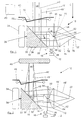
- the laser scanner 10 shown in FIGS. 1 to 8 has a laser 12, in particular pulsed laser, as well as a transmitting optical system 14 comprehensive Transmitting device 16, one provided in particular with a rotating mirror Light deflecting device 18 and a receiving lens 20 and a optoelectronic photoreceiver 22 comprehensive receiving arrangement 24th
- the transmission optics 14 can in particular have a transmission lens 26 and a transmission collimator 28 include.
- the light deflector 18 comprises a mirror 32, which on a attached via a motor 34 about an axis 36 rotatable mirror support 30 is.
- the axis of rotation 36 is parallel to the optical axis of the Reception lens 20.
- the mirror 32 is opposite the rotation axis 36 and corresponding to the optical axis of the receiving lens 20 um 45 ° inclined.
- a central region 38 of the light deflection device 18 receives over the Transmission lens 26 and the transmission collimator 28 light of the laser 12.
- the first vertical light beam is transmitted through the Sendekollimator 28 in a deflected in the horizontal direction, and then from the light deflector 18 in a vertical direction to a windscreen 40 of the laser scanner 10 to be diverted.
- the passing through this windscreen 40 Transmitted light bundle 42 enters the measuring range to be monitored 44. From an object 46 located in the measuring area 44 (cf. FIG. 2), scattered light passes as received light bundle 48 through the Windscreen 40 in the sense of an autocollimation beam path back to Light deflecting device 18.
- That of the light deflector 18 generally in the horizontal direction deflected received light beam 48 is transmitted by the Sendekollimator 28th partially shadowed in a core area 50.
- the not shadowed Part of the received light beam 48 strikes the receiving lens 20 through which it is focused accordingly.
- the described autocollimation beam path is in the present case formed by the beam path of a Autokollimationsetter devise.
- the receiving lens 20 has zones of different focal lengths, in the present Case a radially inner zone 52 of smaller focal length and a radially outer zone 54 relatively larger focal length. Accordingly, the inner zone 52 of the receiving lens 20 to the near zone and the outer zone 54 assigned to the remote area.
- the windscreen 40 is designed such that a transmission by means of within the housing of the laser scanner 10 arranged transmitters 56 and receivers 58 is possible and accordingly a contamination measurement can be carried out. It can be measured using the measured Dirt-related influence of the windscreen 40th penetrating light beam 60 on the degree of contamination of the windscreen 40 are closed.
- Objects at a greater distance can be accessed via the outer zone 54 of the Receiving lens 20 are detected.
- the respective received light bundle runs 48 'at least substantially parallel to the transmitted light beam 42. It is through the receiving lens 20 on the optoelectronic Photoreceiver 22 focused (see in particular Figure 1).
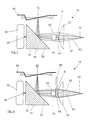
- adjusting means are provided on the size of the core shadow 50 ', 50 "(see Figures 4 to 8) of the receiving light variable are adjustable.
- these adjusting means comprise a Propagation direction of the received light 48 viewed in front of the receiving lens 20 arranged around an axis 62 rotatably mounted aperture 64th
- the axis of rotation 62 extends in the present case parallel to the optical axis the reception lens 20.
- Aperture 64 an elongated shape viewed in the plane of rotation, with respect to the axis of rotation 62 is arranged centrally.
- the aperture 64 is also in relation to the receiving lens 20 is arranged centrally. In the present case this is rotatable diaphragm 64 mounted on the transmission collimator 28.
- the aperture 64 is, for example via a lever 66 between a first Position A, where the core shadow assumes its minimum size, and a second position B adjustable in which the core shadow his maximum size has (see in particular Figures 3 to 6).
- a lever 66 between a first Position A, where the core shadow assumes its minimum size, and a second position B adjustable in which the core shadow his maximum size has (see in particular Figures 3 to 6).
- Figures 3 to 5 which is their first position A engaging aperture 64 is aligned with the transmit collimator 28, so that in this case the relevant core shadow 50 'at least in essentially only by the Sendekollimator 28 is generated (see, in particular FIG. 4).
- the diaphragm 64 assumes its second position, it also carries it for forming the relevant core shadow 50 "(see in particular FIG 5).
- the diaphragm 64 is thus between a first position A, in which the core shadow assumes its minimum size 50 'and at least is essentially generated only by the Sendekollimator 28, and a second position B adjustable in which the core shadow his maximum size is 50 ".
- the position of the optoelectronic photoreceptor 22 can now so can be adjusted that in terms of the more distant objects give the best possible imaging conditions, i. the signal dynamics is minimized.
- conditional signal differences in the near range Objects 46 by an appropriate adjustment of the size of the Kernschattens 50 ', 50 "over the aperture 64 compensated Aperture 64, for example via the lever 66 between the two positions A and B correspondingly adjustable (see in particular Figure 3).
- the aperture 64 takes its first, with the Transmit collimator 28 aligned position A, in which the core shadow its minimum size 50 'and at least substantially only generated by the transmit collimator 28.
- the aperture 64 takes its first, with the Transmit collimator 28 aligned position A, in which the core shadow its minimum size 50 'and at least substantially only generated by the transmit collimator 28.
- the Light exit opening 57 of the collimator 28 can be seen.
- the diaphragm 64 takes its second position B according to FIG one in which the umbra has its maximum size of 50 "and both is generated by the Sendekollimator 28 and through the aperture 64.
- the core shadow becomes 50 ', 50 "increasingly enlarged.
- the diaphragm 64 takes for example her first position A again.
- FIG. 7 shows a plan view of the laser scanner 10 in the direction of the arrow C in Figure 1 with rotated by 90 ° rotating mirror 18 and a beam path, as he is at a contamination of the windscreen 44 and minimal Cover or minimum core shadow 50 'results.
- the aperture So 64 takes her position A here.
- Figure 8 shows again a top view of the laser scanner 10 in the direction of the arrow C in Figure 1 with rotated by 90 ° rotating mirror 18, in In this case, however, with a beam path, as it is in a pollution the windscreen 40 and maximum coverage or maximum Kernschatten 50 "results in.
- the aperture 64 thus takes its position here B on.
- the aperture 64 is in its reproduced in Figure 7 first position A. minimum cover again in the already shown in Figure 4 Way aligned with the Sendekollimator 28. She is between this first position A minimum core shadow 50 'and its second Position B of maximum core shadow 50 "(see Figures 5 and 8) now so adjustable that the near object 46 (see Figure 2) is still detected and Dirt on the windscreen 40 not to false shutdowns to lead.
- the focal point of the near zone is at 76 and the focal point of the far range is indicated at 78.
- FIG. 9 shows a schematic representation of different courses of the over obtained the optoelectronic photoreceptor 22 of the laser scanner Receive signal over the object distance. It is with the curve 68 the course of the sum signal from far and near range, with the Curve 70, the waveform with respect to the far range detecting Linsenzone 54, with the curve 72 of the waveform with respect to the near range detecting lens zone 52 at maximum coverage and with the Curve 74, the waveform with respect to the near zone detecting lens zone 52 played with minimal coverage. With the aperture 64 Here only the near range is influenced accordingly.
- the laser scanner 10 is a control and evaluation electronics 80 (see FIG 1), to which the laser 12, the optoelectronic photoreceiver 22, the transmitter 56, the receiver 58 and / or the motor 34 connected could be.
Landscapes
- Engineering & Computer Science (AREA)
- Physics & Mathematics (AREA)
- General Physics & Mathematics (AREA)
- Remote Sensing (AREA)
- Computer Networks & Wireless Communication (AREA)
- Electromagnetism (AREA)
- Radar, Positioning & Navigation (AREA)
- Computer Vision & Pattern Recognition (AREA)
- Health & Medical Sciences (AREA)
- Theoretical Computer Science (AREA)
- Toxicology (AREA)
- Artificial Intelligence (AREA)
- General Health & Medical Sciences (AREA)
- Optical Radar Systems And Details Thereof (AREA)
- Mechanical Light Control Or Optical Switches (AREA)
- Laser Surgery Devices (AREA)
- Facsimile Heads (AREA)
- Mechanical Optical Scanning Systems (AREA)
- Length Measuring Devices By Optical Means (AREA)
Description
- Figur 1
- eine schematische, teilweise geschnittene Darstellung eines Laserscanners mit einem Strahlenverlauf, wie er sich bei sehr weit entfernten Objekten ergibt,
- Figur 2
- eine schematische, teilweise geschnittene Darstellung des Laserscanners mit einem Strahlenverlauf, wie er sich bei in geringer Entfernung vorgesehenen Objekten ergibt,
- Figur 3
- eine schematische Ansicht der verstellbaren Blende sowie der Empfangslinse des Laserscanners in Richtung des Pfeils F der Figur 1, wobei zwei verschiedene Positionen der verstellbaren Blende dargestellt sind,
- Figur 4
- eine schematische Ansicht des die Sendeanordnung, die verstellbare Blende und die Empfangslinse umfassenden Teils des Laserscanners in Richtung des Pfeils G der Figur 1, wobei die Blende eine erste Position einnimmt, in der der Kernschatten seine minimale Größe annimmt,
- Figur 5
- die gleiche Ansicht wie in der Figur 4, wobei die Blende jedoch eine zweite Position einnimmt, in der der Kernschatten seine maximale Größe aufweist,
- Figur 6
- eine schematische Seitenansicht des die Sendeanordnung, die verstellbare Blende und die Empfangslinse umfassenden Teils des Laserscanners, wobei die Blende beispielsweise wieder ihre erste Position einnimmt,
- Figur 7
- eine Draufsicht des Laserscanners in Richtung des Pfeiles C in Figur 1 mit um 90° gedrehtem Drehspiegel und einem Strahlenverlauf, wie er sich bei einer Verschmutzung der Frontscheibe und minimalem Kernschatten ergibt,
- Figur 8
- eine Draufsicht des Laserscanners entsprechend Figur 7 mit um 90° gedrehtem Drehspiegel und einem Strahlenverlauf, wie er sich bei einer Verschmutzung der Frontscheibe und maximalem Kernschatten ergibt, und
- Figur 9
- ein schematisches Diagramm, in dem verschiedene Verläufe des vom optoelektronischen Photoempfänger gelieferten Empfangssignals über der Objektentfernung dargestellt sind.
- 10
- Laserscanner
- 12
- Laser, Impulslaser
- 14
- Sendeoptik
- 16
- Sendeanordnung
- 18
- Lichtablenkeinrichtung, Drehspiegel
- 20
- Empfangslinse
- 22
- optoelektronischer Photoempfänger
- 24
- Empfangsanordnung
- 26
- Sendelinse
- 28
- Sendekollimator
- 30
- Spiegelträger
- 32
- Spiegel
- 34
- Motor
- 36
- Drehachse
- 38
- zentraler Bereich
- 40
- Frontscheibe
- 42
- Sendelichtbündel
- 44
- Meßbereich
- 46
- Objekt
- 48
- Empfangslichtbündel
- 50
- Kernbereich
- 50'
- minimaler Kernschatten
- 50"
- maximaler Kernschatten
- 52
- innere Zone kleiner Brennweite
- 54
- äußere Zone großer Brennweite
- 56
- Sender
- 57
- Lichtaustrittsöffnung des Kollimators
- 58
- Empfänger
- 60
- Lichtbündel
- 62
- Drehachse
- 64
- Blende
- 66
- Hebel
- 68
- Kurve
- 70
- Kurve
- 72
- Kurve
- 74
- Kurve
- 76
- Brennpunkt des Nahbereichs
- 78
- Brennpunkt des Fernbereichs
- 80
- Steuer- und Auswerteelektronik
- 82
- Empfangslichtbündel der Verschmutzung
- A
- erste Blendenposition
- B
- zweite Blendenposition
Claims (13)
- Laserscanner (10) mit einer einen Laser (12) und eine Sendeoptik (14) umfassenden Sendeanordnung (16), einer Lichtablenkeinrichtung (18) und einer eine Empfangslinse (20) und einen optoelektronischen Photoempfänger (22) umfassenden Empfangsanordnung (24), bei dem von der Sendeanordnung (16) ausgesendetes Licht (42) über die Lichtablenkeinrichtung (18) unter verschiedenen Winkeln durch eine Frontscheibe (40) hindurch in einen Meßbereich (44) lenkbar ist und von einem sich im Meßbereich (44) befindenden Objekt (46) zurückgeworfenes Licht (48) im Sinne eines Autokollimationsstrahlengangs zurück zur Lichtablenkeinrichtung (18) und anschließend zur Empfangsanordnung (24) gelangt, wobei das Empfangslicht (48) in einem Kernbereich (50) zumindest teilweise abgeschattet wird,
dadurch gekennzeichnet, daß Justiermittel (64) vorgesehen sind, über die die Größe des Kernschattens (50', 50") des Empfangslichtes (48) variabel einstellbar ist. - Laserscanner nach Anspruch 1,
dadurch gekennzeichnet, daß die Justiermittel wenigstens eine verstellbare Blende (64) umfassen, wobei insbesondere die Blende (64) in Ausbreitungsrichtung des Empfangslichtes (48) betrachtet vor oder hinter der Empfangslinse (20) angeordnet ist. - Laserscanner nach einem der vorhergehenden Ansprüche,
dadurch gekennzeichnet, daß die Blende (64) um eine Achse (62) drehbar gelagert ist, wobei insbesondere die Drehachse (62) der Blende (64) parallel zur optischen Achse der Empfangslinse (20) verläuft. - Laserscanner nach Anspruch 3,
dadurch gekennzeichnet, daß die um eine Achse (62) drehbar gelagerte Blende (64) eine in der Drehebene betrachtet längliche Gestalt besitzt. - Laserscanner nach einem der vorhergehenden Ansprüche,
dadurch gekennzeichnet, daß die Drehachse (62) bezüglich der sich in der Drehebene ergebenden Gestalt der Blende (64) mittig angeordnet ist, und/oder
daß die gedachte Drehachse (62) der Blende (64) bezüglich der Empfangslinse (20) mittig angeordnet ist. - Laserscanner nach einem der Ansprüche 1 oder 2,
dadurch gekennzeichnet, daß die Blende (64) linear verschiebbar ist, wobei
die Blende (64) insbesondere quer oder parallel zur optischen Achse der Empfangslinse (20) verschiebbar ist, und/oder
daß die Blende (64) entlang der optischen Achse der Empfangslinse (20) verschiebbar ist. - Laserscanner nach einem der vorhergehenden Ansprüche,
dadurch gekennzeichnet, daß die Blende (64) in Richtung eines der Sendeanordnung (16) zugeordneten Kollimators (28) oder quer dazu verschiebbar ist. - Laserscanner nach einem der vorhergehenden Ansprüche,
dadurch gekennzeichnet, daß ein Teil des maximalen Kernschattens (50) durch einen Sendekollimator (28) erzeugt ist, wobei insbesondere die Blende (64) zwischen einer ersten Position (A), in der der Kernschatten (50', 50") seine minimale Größe (50') annimmt und zumindest im wesentlichen nur durch den Sendekollimator (28) erzeugt ist, und einer zweiten Position (B) verstellbar ist, in der der Kernschatten (50) seine maximale Größe (50") annimmt. - Laserscanner nach einem der vorhergehenden Ansprüche,
dadurch gekennzeichnet, daß die Lichtablenkeinrichtung (18) einen Drehspiegel (32) umfaßt. - Laserscanner nach einem der vorhergehenden Ansprüche,
dadurch gekennzeichnet, daß der Autokollimationsstrahlengang durch den Strahlengang einer Autokollimationslichtschranke gebildet ist. - Laserscanner nach einem der vorhergehenden Ansprüche,
dadurch gekennzeichnet, daß die Empfangslinse (20) wenigstens zwei Zonen unterschiedlicher Brennweite aufweist, wobei insbesondere die Empfangslinse (20) wenigstens zwei radial aufeinanderfolgende Zonen (52, 54) unterschiedlicher Brennweite aufweist, und /oder
die Brennweite von Zone zu Zone radial nach außen größer wird. - Laserscanner nach einem der vorhergehenden Ansprüche,
dadurch gekennzeichnet, daß die Brennweite der Empfangslinse (20) zumindest bereichsweise radial von innen nach außen kontinuierlich größer wird. - Laserscanner nach einem der vorhergehenden Ansprüche,
dadurch gekennzeichnet, daß als Laser (12) ein Impulslaser vorgesehen ist.
Applications Claiming Priority (2)
| Application Number | Priority Date | Filing Date | Title |
|---|---|---|---|
| DE10026668A DE10026668A1 (de) | 2000-05-29 | 2000-05-29 | Laserscanner |
| DE10026668 | 2000-05-29 |
Publications (3)
| Publication Number | Publication Date |
|---|---|
| EP1160718A2 EP1160718A2 (de) | 2001-12-05 |
| EP1160718A3 EP1160718A3 (de) | 2004-04-28 |
| EP1160718B1 true EP1160718B1 (de) | 2005-06-22 |
Family
ID=7644024
Family Applications (1)
| Application Number | Title | Priority Date | Filing Date |
|---|---|---|---|
| EP01108942A Expired - Lifetime EP1160718B1 (de) | 2000-05-29 | 2001-04-10 | Laserscanner |
Country Status (3)
| Country | Link |
|---|---|
| EP (1) | EP1160718B1 (de) |
| AT (1) | ATE298442T1 (de) |
| DE (2) | DE10026668A1 (de) |
Cited By (1)
| Publication number | Priority date | Publication date | Assignee | Title |
|---|---|---|---|---|
| EP2287630A1 (de) | 2009-08-20 | 2011-02-23 | Sick Ag | Optoelektronische Erfassungsvorrichtung |
Families Citing this family (18)
| Publication number | Priority date | Publication date | Assignee | Title |
|---|---|---|---|---|
| DE10326848B4 (de) * | 2003-06-14 | 2005-06-23 | Leuze Lumiflex Gmbh + Co. Kg | Optischer Sensor |
| USRE46672E1 (en) | 2006-07-13 | 2018-01-16 | Velodyne Lidar, Inc. | High definition LiDAR system |
| DE102010062616B4 (de) * | 2010-12-08 | 2020-02-13 | pmdtechnologies ag | Optischer Entfernungsmesser |
| DE102012006869A1 (de) * | 2012-04-04 | 2013-10-10 | Valeo Schalter Und Sensoren Gmbh | Optoelektronische Sensoreinrichtung, insbesondere Laserscanner, mit einer angepassten Empfangseinheit zur optimierten Empfangspegelreduzierung |
| US10627490B2 (en) | 2016-01-31 | 2020-04-21 | Velodyne Lidar, Inc. | Multiple pulse, LIDAR based 3-D imaging |
| US12123950B2 (en) | 2016-02-15 | 2024-10-22 | Red Creamery, LLC | Hybrid LADAR with co-planar scanning and imaging field-of-view |
| US12399278B1 (en) | 2016-02-15 | 2025-08-26 | Red Creamery Llc | Hybrid LIDAR with optically enhanced scanned laser |
| US11556000B1 (en) | 2019-08-22 | 2023-01-17 | Red Creamery Llc | Distally-actuated scanning mirror |
| US12399279B1 (en) | 2016-02-15 | 2025-08-26 | Red Creamery Llc | Enhanced hybrid LIDAR with high-speed scanning |
| US10018726B2 (en) | 2016-03-19 | 2018-07-10 | Velodyne Lidar, Inc. | Integrated illumination and detection for LIDAR based 3-D imaging |
| WO2017210418A1 (en) | 2016-06-01 | 2017-12-07 | Velodyne Lidar, Inc. | Multiple pixel scanning lidar |
| CN110914705B (zh) | 2017-03-31 | 2024-04-26 | 威力登激光雷达美国有限公司 | 用于集成lidar照明功率控制的设备、系统和方法 |
| CN110809704B (zh) | 2017-05-08 | 2022-11-01 | 威力登激光雷达美国有限公司 | Lidar数据获取与控制 |
| US11082010B2 (en) | 2018-11-06 | 2021-08-03 | Velodyne Lidar Usa, Inc. | Systems and methods for TIA base current detection and compensation |
| US11885958B2 (en) | 2019-01-07 | 2024-01-30 | Velodyne Lidar Usa, Inc. | Systems and methods for a dual axis resonant scanning mirror |
| US12061263B2 (en) | 2019-01-07 | 2024-08-13 | Velodyne Lidar Usa, Inc. | Systems and methods for a configurable sensor system |
| DE102022129637A1 (de) * | 2022-11-09 | 2024-05-16 | Ifm Electronic Gmbh | Optischer Scanner |
| DE102022129602A1 (de) * | 2022-11-09 | 2024-05-16 | Ifm Electronic Gmbh | Cassegrain-Anordnung für ein optisches Entfernungsmesssystem |
Family Cites Families (4)
| Publication number | Priority date | Publication date | Assignee | Title |
|---|---|---|---|---|
| US5274491A (en) * | 1991-05-13 | 1993-12-28 | Ncr Corporation | Dynamic laser diode aperture for optical scanners |
| US5455669A (en) * | 1992-12-08 | 1995-10-03 | Erwin Sick Gmbh Optik-Elektronik | Laser range finding apparatus |
| DE4412044A1 (de) * | 1994-04-08 | 1995-10-12 | Leuze Electronic Gmbh & Co | Optoelektronische Vorrichtung zum Erfassen von Gegenständen in einem Überwachungsbereich |
| DE19907546C2 (de) * | 1998-03-27 | 2003-02-27 | Leuze Electronic Gmbh & Co | Optoelektronische Vorrichtung |
-
2000
- 2000-05-29 DE DE10026668A patent/DE10026668A1/de not_active Withdrawn
-
2001
- 2001-04-10 AT AT01108942T patent/ATE298442T1/de not_active IP Right Cessation
- 2001-04-10 DE DE50106570T patent/DE50106570D1/de not_active Expired - Lifetime
- 2001-04-10 EP EP01108942A patent/EP1160718B1/de not_active Expired - Lifetime
Cited By (1)
| Publication number | Priority date | Publication date | Assignee | Title |
|---|---|---|---|---|
| EP2287630A1 (de) | 2009-08-20 | 2011-02-23 | Sick Ag | Optoelektronische Erfassungsvorrichtung |
Also Published As
| Publication number | Publication date |
|---|---|
| EP1160718A2 (de) | 2001-12-05 |
| ATE298442T1 (de) | 2005-07-15 |
| EP1160718A3 (de) | 2004-04-28 |
| DE50106570D1 (de) | 2005-07-28 |
| DE10026668A1 (de) | 2001-12-06 |
Similar Documents
| Publication | Publication Date | Title |
|---|---|---|
| EP1160718B1 (de) | Laserscanner | |
| EP0793115B1 (de) | Laser-Radar-Abtaster mit Millimeter-Auflösung | |
| DE3831654C2 (de) | ||
| DE10326848B4 (de) | Optischer Sensor | |
| EP2296002B1 (de) | Optoelektronischer Scanner zur Abstandsbestimmung in Azimut- und Elevationsrichtung | |
| EP2378309B1 (de) | Optoelektronischer Sensor und Verfahren zur Erzeugung von Informationen über Objekte in einem Überwachungsbereich | |
| DE102006027063A1 (de) | Scanner | |
| DE10146692B4 (de) | Entfernungsbildsensor | |
| EP2927711A1 (de) | Laserscanner und Verfahren zur sicheren Erfassung von Objekten | |
| EP1515157A1 (de) | Optoelektronische Erfassungseinrichtung | |
| DE19732776C1 (de) | Optoelektronische Vorrichtung | |
| EP3699638A1 (de) | Optoelektronischer sensor und verfahren zur erfassung eines objekts | |
| DE19936440C2 (de) | Optoelektronische Vorrichtung | |
| DE3602008A1 (de) | Optische abtastvorrichtung mit einem spiegelrad | |
| EP2157449B1 (de) | Lichtgitter | |
| EP2159599A2 (de) | Optoelektronischer sensor | |
| DE2800351A1 (de) | Optische vorrichtung zur bestimmung der lichtaustrittswinkel bei einer mit einem lichtfleck beaufschlagten materialbahn | |
| EP3553564B1 (de) | Entfernungsmessender sensor | |
| DE20118145U1 (de) | Optischer Sensor | |
| DE19619308A1 (de) | Kombinations-Lichttaster | |
| DE2200092B2 (de) | Optische Lesevorrichtung zur Abtastung von Codemarken auf Gegenständen | |
| EP3699637A1 (de) | Optoelektronischer sensor und verfahren zur erfassung eines objekts | |
| DE10356704B4 (de) | Reflexionslichttaster | |
| EP1134595A2 (de) | Verfahren zum Erfassen von Abständen von Objekten mittels eines Triangulations-Sensors und Triangulations-Sensor zum Durchführen des Verfahrens | |
| DE102019111216A1 (de) | Optischer Scanner |
Legal Events
| Date | Code | Title | Description |
|---|---|---|---|
| PUAI | Public reference made under article 153(3) epc to a published international application that has entered the european phase |
Free format text: ORIGINAL CODE: 0009012 |
|
| AK | Designated contracting states |
Kind code of ref document: A2 Designated state(s): AT BE CH CY DE DK ES FI FR GB GR IE IT LI LU MC NL PT SE TR |
|
| AX | Request for extension of the european patent |
Free format text: AL;LT;LV;MK;RO;SI |
|
| PUAL | Search report despatched |
Free format text: ORIGINAL CODE: 0009013 |
|
| AK | Designated contracting states |
Kind code of ref document: A3 Designated state(s): AT BE CH CY DE DK ES FI FR GB GR IE IT LI LU MC NL PT SE TR |
|
| AX | Request for extension of the european patent |
Extension state: AL LT LV MK RO SI |
|
| RIC1 | Information provided on ipc code assigned before grant |
Ipc: 7G 06K 7/10 A Ipc: 7G 01S 17/02 B Ipc: 7G 01S 7/481 B Ipc: 7G 01S 7/497 B Ipc: 7G 01C 3/08 B |
|
| 17P | Request for examination filed |
Effective date: 20040611 |
|
| GRAP | Despatch of communication of intention to grant a patent |
Free format text: ORIGINAL CODE: EPIDOSNIGR1 |
|
| AKX | Designation fees paid |
Designated state(s): AT BE CH CY DE DK ES FI FR GB GR IE IT LI LU MC NL PT SE TR |
|
| GRAS | Grant fee paid |
Free format text: ORIGINAL CODE: EPIDOSNIGR3 |
|
| GRAA | (expected) grant |
Free format text: ORIGINAL CODE: 0009210 |
|
| AK | Designated contracting states |
Kind code of ref document: B1 Designated state(s): AT BE CH CY DE DK ES FI FR GB GR IE IT LI LU MC NL PT SE TR |
|
| PG25 | Lapsed in a contracting state [announced via postgrant information from national office to epo] |
Ref country code: IE Free format text: LAPSE BECAUSE OF FAILURE TO SUBMIT A TRANSLATION OF THE DESCRIPTION OR TO PAY THE FEE WITHIN THE PRESCRIBED TIME-LIMIT Effective date: 20050622 Ref country code: NL Free format text: LAPSE BECAUSE OF FAILURE TO SUBMIT A TRANSLATION OF THE DESCRIPTION OR TO PAY THE FEE WITHIN THE PRESCRIBED TIME-LIMIT Effective date: 20050622 Ref country code: TR Free format text: LAPSE BECAUSE OF FAILURE TO SUBMIT A TRANSLATION OF THE DESCRIPTION OR TO PAY THE FEE WITHIN THE PRESCRIBED TIME-LIMIT Effective date: 20050622 |
|
| REG | Reference to a national code |
Ref country code: GB Ref legal event code: FG4D Free format text: NOT ENGLISH |
|
| REG | Reference to a national code |
Ref country code: CH Ref legal event code: EP |
|
| REG | Reference to a national code |
Ref country code: IE Ref legal event code: FG4D Free format text: LANGUAGE OF EP DOCUMENT: GERMAN |
|
| REF | Corresponds to: |
Ref document number: 50106570 Country of ref document: DE Date of ref document: 20050728 Kind code of ref document: P |
|
| GBT | Gb: translation of ep patent filed (gb section 77(6)(a)/1977) |
Effective date: 20050822 |
|
| PG25 | Lapsed in a contracting state [announced via postgrant information from national office to epo] |
Ref country code: GR Free format text: LAPSE BECAUSE OF FAILURE TO SUBMIT A TRANSLATION OF THE DESCRIPTION OR TO PAY THE FEE WITHIN THE PRESCRIBED TIME-LIMIT Effective date: 20050922 Ref country code: DK Free format text: LAPSE BECAUSE OF FAILURE TO SUBMIT A TRANSLATION OF THE DESCRIPTION OR TO PAY THE FEE WITHIN THE PRESCRIBED TIME-LIMIT Effective date: 20050922 |
|
| REG | Reference to a national code |
Ref country code: SE Ref legal event code: TRGR |
|
| PG25 | Lapsed in a contracting state [announced via postgrant information from national office to epo] |
Ref country code: ES Free format text: LAPSE BECAUSE OF FAILURE TO SUBMIT A TRANSLATION OF THE DESCRIPTION OR TO PAY THE FEE WITHIN THE PRESCRIBED TIME-LIMIT Effective date: 20051003 |
|
| PG25 | Lapsed in a contracting state [announced via postgrant information from national office to epo] |
Ref country code: PT Free format text: LAPSE BECAUSE OF FAILURE TO SUBMIT A TRANSLATION OF THE DESCRIPTION OR TO PAY THE FEE WITHIN THE PRESCRIBED TIME-LIMIT Effective date: 20051129 |
|
| NLV1 | Nl: lapsed or annulled due to failure to fulfill the requirements of art. 29p and 29m of the patents act | ||
| REG | Reference to a national code |
Ref country code: IE Ref legal event code: FD4D |
|
| ET | Fr: translation filed | ||
| PG25 | Lapsed in a contracting state [announced via postgrant information from national office to epo] |
Ref country code: AT Free format text: LAPSE BECAUSE OF NON-PAYMENT OF DUE FEES Effective date: 20060410 |
|
| PG25 | Lapsed in a contracting state [announced via postgrant information from national office to epo] |
Ref country code: BE Free format text: LAPSE BECAUSE OF NON-PAYMENT OF DUE FEES Effective date: 20060430 Ref country code: MC Free format text: LAPSE BECAUSE OF NON-PAYMENT OF DUE FEES Effective date: 20060430 |
|
| PLBE | No opposition filed within time limit |
Free format text: ORIGINAL CODE: 0009261 |
|
| STAA | Information on the status of an ep patent application or granted ep patent |
Free format text: STATUS: NO OPPOSITION FILED WITHIN TIME LIMIT |
|
| 26N | No opposition filed |
Effective date: 20060323 |
|
| BERE | Be: lapsed |
Owner name: SICK A.G. Effective date: 20060430 |
|
| PG25 | Lapsed in a contracting state [announced via postgrant information from national office to epo] |
Ref country code: LU Free format text: LAPSE BECAUSE OF NON-PAYMENT OF DUE FEES Effective date: 20060410 |
|
| PG25 | Lapsed in a contracting state [announced via postgrant information from national office to epo] |
Ref country code: CY Free format text: LAPSE BECAUSE OF FAILURE TO SUBMIT A TRANSLATION OF THE DESCRIPTION OR TO PAY THE FEE WITHIN THE PRESCRIBED TIME-LIMIT Effective date: 20050622 |
|
| PGFP | Annual fee paid to national office [announced via postgrant information from national office to epo] |
Ref country code: SE Payment date: 20120423 Year of fee payment: 12 Ref country code: FI Payment date: 20120420 Year of fee payment: 12 |
|
| REG | Reference to a national code |
Ref country code: SE Ref legal event code: EUG |
|
| PG25 | Lapsed in a contracting state [announced via postgrant information from national office to epo] |
Ref country code: SE Free format text: LAPSE BECAUSE OF NON-PAYMENT OF DUE FEES Effective date: 20130411 |
|
| PG25 | Lapsed in a contracting state [announced via postgrant information from national office to epo] |
Ref country code: FI Free format text: LAPSE BECAUSE OF NON-PAYMENT OF DUE FEES Effective date: 20130410 |
|
| PGFP | Annual fee paid to national office [announced via postgrant information from national office to epo] |
Ref country code: CH Payment date: 20140422 Year of fee payment: 14 |
|
| REG | Reference to a national code |
Ref country code: CH Ref legal event code: PL |
|
| PG25 | Lapsed in a contracting state [announced via postgrant information from national office to epo] |
Ref country code: CH Free format text: LAPSE BECAUSE OF NON-PAYMENT OF DUE FEES Effective date: 20150430 Ref country code: LI Free format text: LAPSE BECAUSE OF NON-PAYMENT OF DUE FEES Effective date: 20150430 |
|
| REG | Reference to a national code |
Ref country code: FR Ref legal event code: PLFP Year of fee payment: 16 |
|
| REG | Reference to a national code |
Ref country code: FR Ref legal event code: PLFP Year of fee payment: 17 |
|
| PGFP | Annual fee paid to national office [announced via postgrant information from national office to epo] |
Ref country code: FR Payment date: 20170424 Year of fee payment: 17 Ref country code: GB Payment date: 20170425 Year of fee payment: 17 |
|
| PGFP | Annual fee paid to national office [announced via postgrant information from national office to epo] |
Ref country code: IT Payment date: 20170420 Year of fee payment: 17 |
|
| GBPC | Gb: european patent ceased through non-payment of renewal fee |
Effective date: 20180410 |
|
| PG25 | Lapsed in a contracting state [announced via postgrant information from national office to epo] |
Ref country code: GB Free format text: LAPSE BECAUSE OF NON-PAYMENT OF DUE FEES Effective date: 20180410 |
|
| PG25 | Lapsed in a contracting state [announced via postgrant information from national office to epo] |
Ref country code: FR Free format text: LAPSE BECAUSE OF NON-PAYMENT OF DUE FEES Effective date: 20180430 Ref country code: IT Free format text: LAPSE BECAUSE OF NON-PAYMENT OF DUE FEES Effective date: 20180410 |
|
| PGFP | Annual fee paid to national office [announced via postgrant information from national office to epo] |
Ref country code: DE Payment date: 20200423 Year of fee payment: 20 |
|
| REG | Reference to a national code |
Ref country code: DE Ref legal event code: R071 Ref document number: 50106570 Country of ref document: DE |