EP1160718B1 - Laser scanner - Google Patents
Laser scanner Download PDFInfo
- Publication number
- EP1160718B1 EP1160718B1 EP01108942A EP01108942A EP1160718B1 EP 1160718 B1 EP1160718 B1 EP 1160718B1 EP 01108942 A EP01108942 A EP 01108942A EP 01108942 A EP01108942 A EP 01108942A EP 1160718 B1 EP1160718 B1 EP 1160718B1
- Authority
- EP
- European Patent Office
- Prior art keywords
- laser scanner
- diaphragm
- accordance
- light
- receiver
- Prior art date
- Legal status (The legal status is an assumption and is not a legal conclusion. Google has not performed a legal analysis and makes no representation as to the accuracy of the status listed.)
- Expired - Lifetime
Links
Images


Classifications
-
- G—PHYSICS
- G06—COMPUTING; CALCULATING OR COUNTING
- G06K—GRAPHICAL DATA READING; PRESENTATION OF DATA; RECORD CARRIERS; HANDLING RECORD CARRIERS
- G06K7/00—Methods or arrangements for sensing record carriers, e.g. for reading patterns
- G06K7/10—Methods or arrangements for sensing record carriers, e.g. for reading patterns by electromagnetic radiation, e.g. optical sensing; by corpuscular radiation
- G06K7/10544—Methods or arrangements for sensing record carriers, e.g. for reading patterns by electromagnetic radiation, e.g. optical sensing; by corpuscular radiation by scanning of the records by radiation in the optical part of the electromagnetic spectrum
- G06K7/10554—Moving beam scanning
- G06K7/10594—Beam path
- G06K7/10603—Basic scanning using moving elements
- G06K7/10613—Basic scanning using moving elements by rotation, e.g. polygon
-
- G—PHYSICS
- G01—MEASURING; TESTING
- G01S—RADIO DIRECTION-FINDING; RADIO NAVIGATION; DETERMINING DISTANCE OR VELOCITY BY USE OF RADIO WAVES; LOCATING OR PRESENCE-DETECTING BY USE OF THE REFLECTION OR RERADIATION OF RADIO WAVES; ANALOGOUS ARRANGEMENTS USING OTHER WAVES
- G01S7/00—Details of systems according to groups G01S13/00, G01S15/00, G01S17/00
- G01S7/48—Details of systems according to groups G01S13/00, G01S15/00, G01S17/00 of systems according to group G01S17/00
- G01S7/481—Constructional features, e.g. arrangements of optical elements
- G01S7/4816—Constructional features, e.g. arrangements of optical elements of receivers alone
-
- G—PHYSICS
- G01—MEASURING; TESTING
- G01S—RADIO DIRECTION-FINDING; RADIO NAVIGATION; DETERMINING DISTANCE OR VELOCITY BY USE OF RADIO WAVES; LOCATING OR PRESENCE-DETECTING BY USE OF THE REFLECTION OR RERADIATION OF RADIO WAVES; ANALOGOUS ARRANGEMENTS USING OTHER WAVES
- G01S7/00—Details of systems according to groups G01S13/00, G01S15/00, G01S17/00
- G01S7/48—Details of systems according to groups G01S13/00, G01S15/00, G01S17/00 of systems according to group G01S17/00
- G01S7/481—Constructional features, e.g. arrangements of optical elements
- G01S7/4817—Constructional features, e.g. arrangements of optical elements relating to scanning
-
- G—PHYSICS
- G01—MEASURING; TESTING
- G01S—RADIO DIRECTION-FINDING; RADIO NAVIGATION; DETERMINING DISTANCE OR VELOCITY BY USE OF RADIO WAVES; LOCATING OR PRESENCE-DETECTING BY USE OF THE REFLECTION OR RERADIATION OF RADIO WAVES; ANALOGOUS ARRANGEMENTS USING OTHER WAVES
- G01S7/00—Details of systems according to groups G01S13/00, G01S15/00, G01S17/00
- G01S7/48—Details of systems according to groups G01S13/00, G01S15/00, G01S17/00 of systems according to group G01S17/00
- G01S7/483—Details of pulse systems
- G01S7/486—Receivers
- G01S7/4868—Controlling received signal intensity or exposure of sensor
-
- G—PHYSICS
- G01—MEASURING; TESTING
- G01S—RADIO DIRECTION-FINDING; RADIO NAVIGATION; DETERMINING DISTANCE OR VELOCITY BY USE OF RADIO WAVES; LOCATING OR PRESENCE-DETECTING BY USE OF THE REFLECTION OR RERADIATION OF RADIO WAVES; ANALOGOUS ARRANGEMENTS USING OTHER WAVES
- G01S7/00—Details of systems according to groups G01S13/00, G01S15/00, G01S17/00
- G01S7/48—Details of systems according to groups G01S13/00, G01S15/00, G01S17/00 of systems according to group G01S17/00
- G01S7/497—Means for monitoring or calibrating
-
- G—PHYSICS
- G06—COMPUTING; CALCULATING OR COUNTING
- G06K—GRAPHICAL DATA READING; PRESENTATION OF DATA; RECORD CARRIERS; HANDLING RECORD CARRIERS
- G06K7/00—Methods or arrangements for sensing record carriers, e.g. for reading patterns
- G06K7/10—Methods or arrangements for sensing record carriers, e.g. for reading patterns by electromagnetic radiation, e.g. optical sensing; by corpuscular radiation
- G06K7/10544—Methods or arrangements for sensing record carriers, e.g. for reading patterns by electromagnetic radiation, e.g. optical sensing; by corpuscular radiation by scanning of the records by radiation in the optical part of the electromagnetic spectrum
- G06K7/10554—Moving beam scanning
- G06K7/10594—Beam path
- G06K7/10683—Arrangement of fixed elements
- G06K7/10702—Particularities of propagating elements, e.g. lenses, mirrors
-
- G—PHYSICS
- G01—MEASURING; TESTING
- G01S—RADIO DIRECTION-FINDING; RADIO NAVIGATION; DETERMINING DISTANCE OR VELOCITY BY USE OF RADIO WAVES; LOCATING OR PRESENCE-DETECTING BY USE OF THE REFLECTION OR RERADIATION OF RADIO WAVES; ANALOGOUS ARRANGEMENTS USING OTHER WAVES
- G01S7/00—Details of systems according to groups G01S13/00, G01S15/00, G01S17/00
- G01S7/48—Details of systems according to groups G01S13/00, G01S15/00, G01S17/00 of systems according to group G01S17/00
- G01S7/497—Means for monitoring or calibrating
- G01S2007/4975—Means for monitoring or calibrating of sensor obstruction by, e.g. dirt- or ice-coating, e.g. by reflection measurement on front-screen
Definitions
- the invention relates to a laser scanner with a laser and a Transmitting optics comprehensive transmission arrangement, a light deflection device and a receiving lens and an optoelectronic photoreceiver comprehensive reception arrangement, in which by the transmission arrangement emitted light on the light deflector under different Angle through a windscreen into a measuring range is steerable and of an object in the measuring range reflected light back in the sense of a Autokollimationsstrahlengangs back to the light deflecting device and then to the receiving device reaches, wherein the received light in a core area at least partially shaded.
- a laser scanner is already known from US Pat. No. 5,455,669 and DE-A-4,412,044. This may in particular to trade a pulse laser scanner with a pulsed laser.
- the requirements of laser scanners especially those in the field the safety technology used pulse laser scanners counts that black objects are still detected in the extreme close range. There this requirement is contrary to the further requirement that Dirt on the windscreen can not be detected as an obstacle is in the usual systems for the transmitted light and the Receiving light provided a Autokollimationsstrahlengang, in which a shaded middle area of the received light by a transmit collimator becomes.
- the receiving lens has several zones of different Focal length, preferably the middle zone being the shortest Focal length. As a result, objects can be at a great distance detected via a radially outer long range of the receiving lens become.
- the received light is largely parallel to the transmitted light, hits the far end of the receiving lens and is on the Receiver focused.
- the aim of the invention is to provide an improved laser scanner of the mentioned type, in which eventual shape tolerances of the receiving lens Compensated in the simplest and most reliable way without increasing the signal dynamics at the same time.
- This object is achieved according to the invention in that adjusting are provided, on the size of the core shadow of the received light is variably adjustable.
- the respective adjusting means expediently comprise at least an adjustable aperture.
- Such a diaphragm can in the propagation direction of the received light considered to be arranged in front of or behind the receiving lens. in principle It is also conceivable, both in front of and behind the receiving lens each to arrange at least one such aperture.
- the respective aperture can be rotatably mounted about an axis or linearly displaceable be.
- the axis of rotation extends preferably parallel to the optical axis of the receiving lens.
- a linearly displaceable diaphragm can, for example, transversely or parallel to be displaced optical optical axis of the receiving lens. In the latter case is the diaphragm preferably displaceable along the respective optical axis.
- the diaphragm is in the direction one of the transmitter assembly associated collimator or across it displaceable.
- a part of the maximum core shadow is already by a Send collimator generated.
- the aperture is expediently between a first position where the core shadow is its minimum Size assumes and at least essentially only by the Sendekollimator is generated, and a second position adjustable, in which Core shadow assumes its maximum size.
- the light deflection device may in particular comprise a rotating mirror.
- Laser scanner is the autocollimation beam through the Beam path of a Autokollimationslicht devise formed.
- Photocells are then in particular also corresponding safety shutdowns possible as soon as a respective object in the supervised Measuring range is detected.
- the receiving lens advantageously at least two zones of different focal lengths.
- at least two radially successive zones provided different focal length, in which case the Focal length advantageously greater from zone to zone radially outward becomes.
- a pulsed laser is preferably provided.
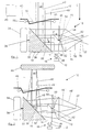
- the laser scanner 10 shown in FIGS. 1 to 8 has a laser 12, in particular pulsed laser, as well as a transmitting optical system 14 comprehensive Transmitting device 16, one provided in particular with a rotating mirror Light deflecting device 18 and a receiving lens 20 and a optoelectronic photoreceiver 22 comprehensive receiving arrangement 24th
- the transmission optics 14 can in particular have a transmission lens 26 and a transmission collimator 28 include.
- the light deflector 18 comprises a mirror 32, which on a attached via a motor 34 about an axis 36 rotatable mirror support 30 is.
- the axis of rotation 36 is parallel to the optical axis of the Reception lens 20.
- the mirror 32 is opposite the rotation axis 36 and corresponding to the optical axis of the receiving lens 20 um 45 ° inclined.
- a central region 38 of the light deflection device 18 receives over the Transmission lens 26 and the transmission collimator 28 light of the laser 12.
- the first vertical light beam is transmitted through the Sendekollimator 28 in a deflected in the horizontal direction, and then from the light deflector 18 in a vertical direction to a windscreen 40 of the laser scanner 10 to be diverted.
- the passing through this windscreen 40 Transmitted light bundle 42 enters the measuring range to be monitored 44. From an object 46 located in the measuring area 44 (cf. FIG. 2), scattered light passes as received light bundle 48 through the Windscreen 40 in the sense of an autocollimation beam path back to Light deflecting device 18.
- That of the light deflector 18 generally in the horizontal direction deflected received light beam 48 is transmitted by the Sendekollimator 28th partially shadowed in a core area 50.
- the not shadowed Part of the received light beam 48 strikes the receiving lens 20 through which it is focused accordingly.
- the described autocollimation beam path is in the present case formed by the beam path of a Autokollimationsetter devise.
- the receiving lens 20 has zones of different focal lengths, in the present Case a radially inner zone 52 of smaller focal length and a radially outer zone 54 relatively larger focal length. Accordingly, the inner zone 52 of the receiving lens 20 to the near zone and the outer zone 54 assigned to the remote area.
- the windscreen 40 is designed such that a transmission by means of within the housing of the laser scanner 10 arranged transmitters 56 and receivers 58 is possible and accordingly a contamination measurement can be carried out. It can be measured using the measured Dirt-related influence of the windscreen 40th penetrating light beam 60 on the degree of contamination of the windscreen 40 are closed.
- Objects at a greater distance can be accessed via the outer zone 54 of the Receiving lens 20 are detected.
- the respective received light bundle runs 48 'at least substantially parallel to the transmitted light beam 42. It is through the receiving lens 20 on the optoelectronic Photoreceiver 22 focused (see in particular Figure 1).
- adjusting means are provided on the size of the core shadow 50 ', 50 "(see Figures 4 to 8) of the receiving light variable are adjustable.
- these adjusting means comprise a Propagation direction of the received light 48 viewed in front of the receiving lens 20 arranged around an axis 62 rotatably mounted aperture 64th
- the axis of rotation 62 extends in the present case parallel to the optical axis the reception lens 20.
- Aperture 64 an elongated shape viewed in the plane of rotation, with respect to the axis of rotation 62 is arranged centrally.
- the aperture 64 is also in relation to the receiving lens 20 is arranged centrally. In the present case this is rotatable diaphragm 64 mounted on the transmission collimator 28.
- the aperture 64 is, for example via a lever 66 between a first Position A, where the core shadow assumes its minimum size, and a second position B adjustable in which the core shadow his maximum size has (see in particular Figures 3 to 6).
- a lever 66 between a first Position A, where the core shadow assumes its minimum size, and a second position B adjustable in which the core shadow his maximum size has (see in particular Figures 3 to 6).
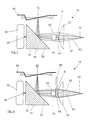
- Figures 3 to 5 which is their first position A engaging aperture 64 is aligned with the transmit collimator 28, so that in this case the relevant core shadow 50 'at least in essentially only by the Sendekollimator 28 is generated (see, in particular FIG. 4).
- the diaphragm 64 assumes its second position, it also carries it for forming the relevant core shadow 50 "(see in particular FIG 5).
- the diaphragm 64 is thus between a first position A, in which the core shadow assumes its minimum size 50 'and at least is essentially generated only by the Sendekollimator 28, and a second position B adjustable in which the core shadow his maximum size is 50 ".
- the position of the optoelectronic photoreceptor 22 can now so can be adjusted that in terms of the more distant objects give the best possible imaging conditions, i. the signal dynamics is minimized.
- conditional signal differences in the near range Objects 46 by an appropriate adjustment of the size of the Kernschattens 50 ', 50 "over the aperture 64 compensated Aperture 64, for example via the lever 66 between the two positions A and B correspondingly adjustable (see in particular Figure 3).
- the aperture 64 takes its first, with the Transmit collimator 28 aligned position A, in which the core shadow its minimum size 50 'and at least substantially only generated by the transmit collimator 28.
- the aperture 64 takes its first, with the Transmit collimator 28 aligned position A, in which the core shadow its minimum size 50 'and at least substantially only generated by the transmit collimator 28.
- the Light exit opening 57 of the collimator 28 can be seen.
- the diaphragm 64 takes its second position B according to FIG one in which the umbra has its maximum size of 50 "and both is generated by the Sendekollimator 28 and through the aperture 64.
- the core shadow becomes 50 ', 50 "increasingly enlarged.
- the diaphragm 64 takes for example her first position A again.
- FIG. 7 shows a plan view of the laser scanner 10 in the direction of the arrow C in Figure 1 with rotated by 90 ° rotating mirror 18 and a beam path, as he is at a contamination of the windscreen 44 and minimal Cover or minimum core shadow 50 'results.
- the aperture So 64 takes her position A here.
- Figure 8 shows again a top view of the laser scanner 10 in the direction of the arrow C in Figure 1 with rotated by 90 ° rotating mirror 18, in In this case, however, with a beam path, as it is in a pollution the windscreen 40 and maximum coverage or maximum Kernschatten 50 "results in.
- the aperture 64 thus takes its position here B on.
- the aperture 64 is in its reproduced in Figure 7 first position A. minimum cover again in the already shown in Figure 4 Way aligned with the Sendekollimator 28. She is between this first position A minimum core shadow 50 'and its second Position B of maximum core shadow 50 "(see Figures 5 and 8) now so adjustable that the near object 46 (see Figure 2) is still detected and Dirt on the windscreen 40 not to false shutdowns to lead.
- the focal point of the near zone is at 76 and the focal point of the far range is indicated at 78.
- FIG. 9 shows a schematic representation of different courses of the over obtained the optoelectronic photoreceptor 22 of the laser scanner Receive signal over the object distance. It is with the curve 68 the course of the sum signal from far and near range, with the Curve 70, the waveform with respect to the far range detecting Linsenzone 54, with the curve 72 of the waveform with respect to the near range detecting lens zone 52 at maximum coverage and with the Curve 74, the waveform with respect to the near zone detecting lens zone 52 played with minimal coverage. With the aperture 64 Here only the near range is influenced accordingly.
- the laser scanner 10 is a control and evaluation electronics 80 (see FIG 1), to which the laser 12, the optoelectronic photoreceiver 22, the transmitter 56, the receiver 58 and / or the motor 34 connected could be.
Abstract
Description
Die Erfindung betrifft einen Laserscanner mit einer einen Laser und eine Sendeoptik umfassenden Sendeanordnung, einer Lichtablenkeinrichtung und einer eine Empfangslinse und einen optoelektronischen Photoempfänger umfassenden Empfangsanordnung, bei dem von der Sendeanordnung ausgesendetes Licht über die Lichtablenkeinrichtung unter verschiedenen Winkeln durch eine Frontscheibe hindurch in einen Meßbereich lenkbar ist und von einem sich im Meßbereich befindenden Objekt zurückgeworfenes Licht im Sinne eines Autokollimationsstrahlengangs zurück zur Lichtablenkeinrichtung und anschließend zur Empfangsanordnung gelangt, wobei das Empfangslicht in einem Kernbereich zumindest teilweise abgeschattet wird. Ein solcher Laserscanner ist aus US-A-5 455 669 und DE-A-4 412 044 schon bekannt. Hierbei kann es sich insbesondere um einen Pulslaserscanner mit einem Impulslaser handeln.The invention relates to a laser scanner with a laser and a Transmitting optics comprehensive transmission arrangement, a light deflection device and a receiving lens and an optoelectronic photoreceiver comprehensive reception arrangement, in which by the transmission arrangement emitted light on the light deflector under different Angle through a windscreen into a measuring range is steerable and of an object in the measuring range reflected light back in the sense of a Autokollimationsstrahlengangs back to the light deflecting device and then to the receiving device reaches, wherein the received light in a core area at least partially shaded. Such a laser scanner is already known from US Pat. No. 5,455,669 and DE-A-4,412,044. This may in particular to trade a pulse laser scanner with a pulsed laser.
Zu den Anforderungen bei Laserscannern wie insbesondere den im Bereich der Sicherheitstechnik eingesetzten Pulslaserscannern zählt, daß schwarze Objekte auch im extremen Nahbereich noch erfaßt werden. Da diese Anforderung im Gegensatz zu der weiteren Forderung steht, daß Verschmutzungen auf der Frontscheibe nicht als Hindernis erfaßt werden dürfen, ist bei den bisher üblichen Systemen für das Sendelicht und das Empfangslicht ein Autokollimationsstrahlengang vorgesehen, bei dem ein mittlerer Bereich des Empfangslichtes durch einen Sendekollimator abgeschattet wird. Dabei besitzt die Empfangslinse mehrere Zonen unterschiedlicher Brennweite, wobei vorzugsweise die mittlere Zone die kürzeste Brennweite aufweist. Demzufolge können Objekte in großer Entfernung über einen radial äußeren Fernbereich der Empfangslinse erfaßt werden. Das Empfangslicht verläuft dabei weitgehend parallel zum Sendelicht, trifft auf den Fernbereich der Empfangslinse und wird auf den Empfänger fokussiert. Je näher das Objekt vor der Empfangslinse liegt, desto weiter wandert der Brennpunkt des Empfangslichtbündels hinter den Empfänger. Ab einem bestimmten Abstand ist das Objekt nicht mehr erfaßbar. Durch die kürzere Brennweite des radial innenliegenden Nahbereichs der Empfangslinse wird das von einem näher gelegenen Objekt stammende Empfangslichtbündel über diesen Nahbereich auf den Empfänger fokussiert. Damit sind auch sich in der Nähe des Laserscanners befindende Objekte erfaßbar.The requirements of laser scanners, especially those in the field the safety technology used pulse laser scanners counts that black objects are still detected in the extreme close range. There this requirement is contrary to the further requirement that Dirt on the windscreen can not be detected as an obstacle is in the usual systems for the transmitted light and the Receiving light provided a Autokollimationsstrahlengang, in which a shaded middle area of the received light by a transmit collimator becomes. The receiving lens has several zones of different Focal length, preferably the middle zone being the shortest Focal length. As a result, objects can be at a great distance detected via a radially outer long range of the receiving lens become. The received light is largely parallel to the transmitted light, hits the far end of the receiving lens and is on the Receiver focused. The closer the object is in front of the receiving lens, the farther the focus of the received light beam travels the recipient. At a certain distance, the object is no longer detectable. Due to the shorter focal length of the radially inner short range the receiving lens becomes that of a closer object originating received light bundles over this short range on the receiver focused. This also puts you in the vicinity of the laser scanner be detected objects.
Bei einer solchen Anordnung tritt nun aber das Problem auf, daß infolge von Formtoleranzen der Empfangslinse der minimale Abstand, bei dem ein nahes Objekt noch erfaßt werden kann, stark variiert. Bisher werden solche Abweichungen ausschließlich über eine entsprechende Änderung der Position des Empfängers entsprechend korrigiert. Dabei wird der Empfänger so justiert, daß sowohl von einem nahen Objekt als auch von einem fernen Objekt noch genügend Licht auf den Empfänger fällt, um das betreffende Objekt erfassen zu können. Eine solche Einstellung der Empfängerposition stellt nun aber lediglich einen Kompromiß zwischen einer optimalen Abbildung für den Fernbereich und einem ausreichenden Signal für den Nahbereich dar. Da damit insbesondere auch die Signaldynamik, d.h. das Verhältnis von maximalem Signal zu minimalem Signal, größer wird, wird der betreffende Scanner auch empfindlicher, was dazu führen kann, daß ungewollt insbesondere auch Staubwolken, Dämpfe und/oder dergleichen erfaßt werden. Entsprechend kann diese Überempfindlichkeit im Zusammenhang mit der üblicherweise vorhandenen Lichtschrankenfunktion zu unerwünschten Abschaltungen führen. Dabei können insbesondere auch Verschmutzungen der Frontscheibe solche Fehlabschaltungen zur Folge haben.In such an arrangement, but now the problem arises that as a result of shape tolerances of the receiving lens the minimum distance at which a Near object can still be detected, varies greatly. So far, such Deviations exclusively through a corresponding change in the Position of the receiver corrected accordingly. In the process, the recipient becomes adjusted so that both from a near object and from one distant object still enough light falls on the receiver to the relevant To capture object. Such a setting of the receiver position But now only a compromise between an optimal Illustration for the far range and a sufficient signal for the near range. Since in particular the signal dynamics, i.e. the ratio of maximum signal to minimum signal, larger the scanner in question will also be more sensitive, which will lead to it can that unwanted especially dust clouds, vapors and / or the like are detected. Accordingly, this hypersensitivity in connection with the commonly existing photoelectric barrier function lead to unwanted shutdowns. It can in particular Even soiling of the windscreen such Fehlabschaltungen have as a consequence.
Ziel der Erfindung ist es, einen verbesserten Laserscanner der eingangs genannten Art zu schaffen, bei dem eventuelle Formtoleranzen der Empfangslinse auf möglichst einfache und zuverlässige Weise kompensierbar sind, ohne dabei gleichzeitig auch die Signaldynamik zu vergrößern.The aim of the invention is to provide an improved laser scanner of the mentioned type, in which eventual shape tolerances of the receiving lens Compensated in the simplest and most reliable way without increasing the signal dynamics at the same time.
Diese Aufgabe wird nach der Erfindung dadurch gelöst, daß Justiermittel vorgesehen sind, über die die Größe des Kernschattens des Empfangslichtes variabel einstellbar ist.This object is achieved according to the invention in that adjusting are provided, on the size of the core shadow of the received light is variably adjustable.
Aufgrund dieser Ausbildung können die sich bei Objekten im Nahbereich ergebenden, auf die Formtoleranzen der Empfangslinse zurückgehenden Signalunterschiede auf einfache und zuverlässige Weise dadurch kompensiert werden, daß über die betreffenden Justiermittel die Größe des Kernschattens des Empfangslichtes entsprechend verändert wird. Die Signaldynamik wird dadurch nicht beeinflußt. Diese kann vielmehr durch eine entsprechende Einstellung der Empfängerposition minimiert werden, um auch für weiter entfernte Objekte möglichst optimale Abbildungsverhältnisse zu erhalten.Due to this training, they can be used for close-up objects resulting, due to the shape tolerances of the receiving lens Compensated signal differences in a simple and reliable way thereby compensated be that about the relevant adjustment the size of the core shadow of the received light is changed accordingly. The signal dynamics is not influenced by it. This can be done by a corresponding setting of the receiver position can be minimized, in order to achieve the best possible imaging conditions for objects that are further away to obtain.
Die betreffenden Justiermittel umfassen zweckmäßigerweise wenigstens eine verstellbare Blende. The respective adjusting means expediently comprise at least an adjustable aperture.
Eine solche Blende kann in Ausbreitungsrichtung des Empfangslichtes betrachtet vor oder hinter der Empfangslinse angeordnet sein. Grundsätzlich ist es auch denkbar, sowohl vor als auch hinter der Empfangslinse jeweils wenigstens eine solche Blende anzuordnen.Such a diaphragm can in the propagation direction of the received light considered to be arranged in front of or behind the receiving lens. in principle It is also conceivable, both in front of and behind the receiving lens each to arrange at least one such aperture.
Die jeweilige Blende kann um eine Achse drehbar gelagert oder linear verschiebbar sein.The respective aperture can be rotatably mounted about an axis or linearly displaceable be.
Ist die Blende um eine Achse drehbar gelagert, so verläuft die Drehachse vorzugsweise parallel zur optischen Achse der Empfangslinse.If the diaphragm is rotatably mounted about an axis, the axis of rotation extends preferably parallel to the optical axis of the receiving lens.
Eine linear verschiebbar Blende kann beispielsweise quer oder parallel zur optischen Achse der Empfangslinse verschiebbar sein. Im letzteren Fall ist die Blende vorzugsweise entlang der betreffenden optischen Achse verschiebbar.A linearly displaceable diaphragm can, for example, transversely or parallel to be displaced optical optical axis of the receiving lens. In the latter case is the diaphragm preferably displaceable along the respective optical axis.
Bei einer weiteren vorteilhaften Ausführungsform ist die Blende in Richtung eines der Sendeanordnung zugeordneten Kollimators oder quer dazu verschiebbar.In a further advantageous embodiment, the diaphragm is in the direction one of the transmitter assembly associated collimator or across it displaceable.
Vorzugsweise ist ein Teil des maximalen Kernschattens bereits durch einen Sendekollimator erzeugt. In diesem Fall ist die Blende zweckmäßigerweise zwischen einer ersten Position, in der der Kernschatten seine minimale Größe annimmt und zumindest im wesentlichen nur durch den Sendekollimator erzeugt ist, und einer zweiten Position verstellbar, in der der Kernschatten seine maximale Größe annimmt. Preferably, a part of the maximum core shadow is already by a Send collimator generated. In this case, the aperture is expediently between a first position where the core shadow is its minimum Size assumes and at least essentially only by the Sendekollimator is generated, and a second position adjustable, in which Core shadow assumes its maximum size.
Die Lichtablenkeinrichtung kann insbesondere einen Drehspiegel umfassen.The light deflection device may in particular comprise a rotating mirror.
Bei einer bevorzugten praktischen Ausführungsform des erfindungsgemäßen Laserscanners ist der Autokollimationsstrahlengang durch den Strahlengang einer Autokollimationslichtschranke gebildet. Über eine solche Lichtschranke sind dann insbesondere auch entsprechende Sicherheitsabschaltungen möglich, sobald ein jeweiliges Objekt im überwachten Meßbereich erfaßt wird.In a preferred practical embodiment of the invention Laser scanner is the autocollimation beam through the Beam path of a Autokollimationslichtschranke formed. About such Photocells are then in particular also corresponding safety shutdowns possible as soon as a respective object in the supervised Measuring range is detected.
Um insbesondere auch sehr nahe am Laserscanner angeordnete Objekte zuverlässig und sicher erkennen zu können, weist die Empfangslinse vorteilhafterweise wenigstens zwei Zonen unterschiedlicher Brennweite auf. Dabei sind vorzugsweise wenigstens zwei radial aufeinanderfolgende Zonen unterschiedlicher Brennweite vorgesehen, wobei in diesem Fall die Brennweite vorteilhafterweise von Zone zu Zone radial nach außen größer wird.In particular, also very close to the laser scanner arranged objects To be able to reliably and reliably recognize the receiving lens advantageously at least two zones of different focal lengths. In this case, preferably at least two radially successive zones provided different focal length, in which case the Focal length advantageously greater from zone to zone radially outward becomes.
Es ist jedoch auch eine solche Ausführungsform denkbar, bei der die Brennweite der Empfangslinse zumindest bereichsweise radial von innen nach außen kontinuierlich größer wird.However, it is also conceivable such an embodiment in which the Focal length of the receiving lens at least partially radially from the inside becomes continuously larger towards the outside.
Als Laser ist vorzugsweise ein Impulslaser vorgesehen.As laser, a pulsed laser is preferably provided.
Die Erfindung wird im folgenden anhand eines Ausführungsbeispiels unter Bezugnahme auf die Zeichnung näher erläutert; in dieser zeigen:
- Figur 1
- eine schematische, teilweise geschnittene Darstellung eines Laserscanners mit einem Strahlenverlauf, wie er sich bei sehr weit entfernten Objekten ergibt,
- Figur 2
- eine schematische, teilweise geschnittene Darstellung des Laserscanners mit einem Strahlenverlauf, wie er sich bei in geringer Entfernung vorgesehenen Objekten ergibt,
- Figur 3
- eine schematische Ansicht der verstellbaren Blende sowie der Empfangslinse des Laserscanners in Richtung des Pfeils F der Figur 1, wobei zwei verschiedene Positionen der verstellbaren Blende dargestellt sind,
- Figur 4
- eine schematische Ansicht des die Sendeanordnung, die verstellbare Blende und die Empfangslinse umfassenden Teils des Laserscanners in Richtung des Pfeils G der Figur 1, wobei die Blende eine erste Position einnimmt, in der der Kernschatten seine minimale Größe annimmt,
- Figur 5
- die gleiche Ansicht wie in der Figur 4, wobei die Blende jedoch eine zweite Position einnimmt, in der der Kernschatten seine maximale Größe aufweist,
- Figur 6
- eine schematische Seitenansicht des die Sendeanordnung, die verstellbare Blende und die Empfangslinse umfassenden Teils des Laserscanners, wobei die Blende beispielsweise wieder ihre erste Position einnimmt,
- Figur 7
- eine Draufsicht des Laserscanners in Richtung des Pfeiles C in Figur 1 mit um 90° gedrehtem Drehspiegel und einem Strahlenverlauf, wie er sich bei einer Verschmutzung der Frontscheibe und minimalem Kernschatten ergibt,
- Figur 8
- eine Draufsicht des Laserscanners entsprechend Figur 7 mit um 90° gedrehtem Drehspiegel und einem Strahlenverlauf, wie er sich bei einer Verschmutzung der Frontscheibe und maximalem Kernschatten ergibt, und
- Figur 9
- ein schematisches Diagramm, in dem verschiedene Verläufe des vom optoelektronischen Photoempfänger gelieferten Empfangssignals über der Objektentfernung dargestellt sind.
- FIG. 1
- a schematic, partially sectioned view of a laser scanner with a beam path, as it results in very distant objects,
- FIG. 2
- a schematic, partially sectioned view of the laser scanner with a beam path, as it results in provided at close range objects,
- FIG. 3
- 1 is a schematic view of the adjustable diaphragm and the receiving lens of the laser scanner in the direction of the arrow F of FIG. 1, wherein two different positions of the adjustable diaphragm are shown;
- FIG. 4
- 1 is a schematic view of the portion of the laser scanner comprising the transmitting device, the adjustable diaphragm and the receiving lens in the direction of the arrow G of FIG. 1, the diaphragm assuming a first position in which the core shadow assumes its minimum size;
- FIG. 5
- the same view as in FIG. 4, but with the diaphragm assuming a second position, in which the core shadow has its maximum size,
- FIG. 6
- a schematic side view of the transmitting device, the adjustable aperture and the receiving lens comprising part of the laser scanner, wherein the aperture, for example, resumes its first position,
- FIG. 7
- a top view of the laser scanner in the direction of arrow C in Figure 1 with rotated by 90 ° rotating mirror and a beam path, as it results in a contamination of the windshield and minimal core shadow,
- FIG. 8
- a top view of the laser scanner according to Figure 7 with rotated by 90 ° rotating mirror and a beam path, as it results in a contamination of the windshield and maximum core shadow, and
- FIG. 9
- a schematic diagram in which different profiles of the received signal supplied by the optoelectronic photoreceptor signal over the object distance are shown.
Der in den Figuren 1 bis 8 gezeigte Laserscanner 10 besitzt eine einen Laser
12, insbesondere Impulslaser, sowie eine Sendeoptik 14 umfassende
Sendeanordnung 16, eine insbesondere mit einem Drehspiegel versehene
Lichtablenkeinrichtung 18 und eine eine Empfangslinse 20 sowie einen
optoelektronischen Photoempfänger 22 umfassende Empfangsanordnung
24.The
Die Sendeoptik 14 kann insbesondere eine Sendelinse 26 und einen Sendekollimator
28 umfassen. The
Die Lichtablenkeinrichtung 18 umfaßt einen Spiegel 32, der auf einem
über einen Motor 34 um eine Achse 36 drehbaren Spiegelträger 30 angebracht
ist. Die Drehachse 36 verläuft parallel zur optischen Achse der
Empfangslinse 20. Der Spiegel 32 ist gegenüber der Drehachse 36 und
entsprechend gegenüber der optischen Achse der Empfangslinse 20 um
45° geneigt.The
Ein zentraler Bereich 38 der Lichtablenkeinrichtung 18 empfängt über die
Sendelinse 26 und den Sendekollimator 28 Licht des Lasers 12. Das zunächst
vertikale Lichtbündel wird durch den Sendekollimator 28 in eine
horizontale Richtung umgelenkt, um dann von der Lichtablenkeinrichtung
18 in eine vertikale Richtung zu einer Frontscheibe 40 des Laserscanners
10 umgelenkt zu werden. Das durch diese Frontscheibe 40 hindurchgehende
Sendelichtbündel 42 gelangt in den zu überwachenden Meßbereich
44. Von einem sich im Meßbereich 44 befindenden Objekt 46 (vgl. insbesondere
Figur 2) gelangt Streulicht als Empfangslichtbündel 48 durch die
Frontscheibe 40 im Sinne eines Autokollimationsstrahlengangs zurück zur
Lichtablenkeinrichtung 18.A
Das von der Lichtablenkeinrichtung 18 allgemein in horizontaler Richtung
umgelenkte Empfangslichtbündel 48 wird durch den Sendekollimator 28
in einem Kernbereich 50 zum Teil abgeschattet. Der nicht abgeschattete
Teil des Empfangslichtbündel 48 trifft auf die Empfangslinse 20, durch die
es entsprechend fokussiert wird.That of the
Der beschriebene Autokollimationsstrahlengang ist im vorliegenden Fall durch den Strahlengang einer Autokollimationslichtschranke gebildet. The described autocollimation beam path is in the present case formed by the beam path of a Autokollimationslichtschranke.
Die Empfangslinse 20 besitzt Zonen unterschiedlicher Brennweite, im vorliegenden
Fall eine radial innere Zone 52 kleinerer Brennweite und eine
radial äußere Zone 54 relativ größerer Brennweite. Entsprechend ist die
innere Zone 52 der Empfangslinse 20 dem Nahbereich und die äußere Zone
54 dem Fernbereich zugeordnet.The receiving
Die Frontscheibe 40 ist derart ausgeführt, daß eine Durchstrahlung mittels
innerhalb des Gehäuses des Laserscanners 10 angeordneten Sendern
56 und Empfängern 58 möglich ist und entsprechend eine Verschmutzungsmessung
durchgeführt werden kann. Dabei kann anhand der gemessenen
schmutzbedingten Beeinflussung der die Frontscheibe 40
durchdringenden Lichtbündel 60 auf den Verschmutzungsgrad der Frontscheibe
40 geschlossen werden.The
Objekte in größerer Entfernung können über die äußere Zone 54 der
Empfangslinse 20 erfaßt werden. Dabei verläuft das betreffende Empfangslichtbündel
48' zumindest im wesentlichen parallel zum Sendelichtbündel
42. Es wird durch die Empfangslinse 20 auf den optoelektronischen
Photoempfänger 22 fokussiert (vgl. insbesondere Figur 1).Objects at a greater distance can be accessed via the
Je näher das Objekt 46 vor der Empfangslinse 20 liegt, desto weiter wandert
das Empfangslichtbündel 48' hinter den Photoempfänger 22 (vgl. z.B.
Figur 2). Da die dem Nahbereich zugeordnete innere Zone 52 der Empfangslinse
20 eine kürzere Brennweite besitzt, wird das Empfangslichtbündel
48" auf den Photoempfänger 22 fokussiert. Damit sind auch Objekte
in der Nähe des Laserscanners 10 erfaßbar. The closer the
Um durch Formtoleranzen der Empfangslinse 20 bedingte Signalunterschiede
bei sich im Nahbereich befindenden Objekten ausgleichen zu
können, sind Justiermittel vorgesehen, über die die Größe des Kernschattens
50', 50" (vgl. die Figuren 4 bis 8) des Empfangslichtes variabel
einstellbar sind. Im vorliegenden Fall umfassen diese Justiermittel eine in
Ausbreitungsrichtung des Empfangslichtes 48 betrachtet vor der Empfangslinse
20 angeordnete, um eine Achse 62 drehbar gelagerte Blende 64.
Die Drehachse 62 verläuft im vorliegenden Fall parallel zur optischen Achse
der Empfangslinse 20.To signal due to shape tolerances of the receiving
Wie am besten anhand der Figuren 3 bis 5 zu erkennen ist, besitzt die
Blende 64 eine in der Drehebene betrachtet längliche Gestalt, bezüglich
der die Drehachse 62 mittig angeordnet ist. Die Blende 64 ist auch bezüglich
der Empfangslinse 20 mittig angeordnet. Im vorliegenden Fall ist diese
drehbare Blende 64 am Sendekollimator 28 gelagert.As best seen with reference to Figures 3 to 5, has the
Die Blende 64 ist beispielsweise über einen Hebel 66 zwischen einer ersten
Position A, in der der Kernschatten seine minimale Größe annimmt,
und einer zweiten Position B verstellbar, in der der Kernschatten seine
maximale Größe besitzt (vgl. insbesondere die Figuren 3 bis 6). Wie insbesondere
anhand der Figuren 3 bis 5 zu erkennen ist, ist die ihre erste Position
A einnehmende Blende 64 mit dem Sendekollimator 28 ausgerichtet,
so daß in diesem Fall der betreffende Kernschatten 50' zumindest im
wesentlichen nur durch den Sendekollimator 28 erzeugt ist (vgl. insbesondere
Figur 4). The
Nimmt die Blende 64 dagegen ihre zweite Position ein, so trägt auch sie
zur Bildung des betreffenden Kernschattens 50" bei (vgl. insbesondere Figur
5).On the other hand, if the
Im vorliegenden Fall ist die Blende 64 somit zwischen einer ersten Position
A, in der der Kernschatten seine minimale Größe 50' annimmt und zumindest
im wesentlichen nur durch den Sendekollimator 28 erzeugt ist,
und einer zweiten Position B verstellbar, in der der Kernschatten seine
maximale Größe 50" annimmt.In the present case, the
Die Position des optoelektronischen Photoempfängers 22 kann nun so
eingestellt werden, daß sich hinsichtlich der weiter entfernten Objekte
möglichst optimale Abbildungsverhältnisse ergeben, d.h. die Signaldynamik
minimiert wird. Dagegen werden durch Formtoleranzen der Empfangslinse
20 bedingte Signalunterschiede bei sich im Nahbereich befindenden
Objekten 46 durch eine entsprechende Einstellung der Größe des
Kernschattens 50', 50" über die Blende 64 kompensiert. Dazu ist die
Blende 64 beispielsweise über den Hebel 66 zwischen den beiden Positionen
A und B entsprechend verstellbar (vgl. insbesondere Figur 3).The position of the
In der Darstellung gemäß Figur 4 nimmt die Blende 64 ihre erste, mit dem
Sendekollimator 28 ausgerichtete Position A ein, in der der Kernschatten
seine minimale Größe 50' aufweist und zumindest im wesentlichen nur
durch den Sendekollimator 28 erzeugt ist. In dieser Figur 4 ist auch die
Lichtaustrittsöffnung 57 des Kollimators 28 zu erkennen.In the illustration of Figure 4, the
Dagegen nimmt die Blende 64 gemäß der Figur 5 ihre zweite Position B
ein, in der der Kernschatten seine maximale Größe 50" besitzt und sowohl
durch den Sendekollimator 28 als auch durch die Blende 64 erzeugt wird.
Beim Übergang von der Position A zur Position B wird der Kernschatten
50', 50" zunehmend vergrößert.In contrast, the
In der Seitenansicht gemäß Figur 6 nimmt die Blende 64 beispielsweise
wieder ihre erste Position A ein.In the side view according to FIG. 6, the
Figur 7 zeigt eine Draufsicht des Laserscanners 10 in Richtung des Pfeiles
C in Figur 1 mit um 90° gedrehtem Drehspiegel 18 und einem Strahlenverlauf,
wie er sich bei einer Verschmutzung der Frontscheibe 44 und minimaler
Abdeckung bzw. minimalem Kernschatten 50' ergibt. Die Blende
64 nimmt hier also ihre Position A ein.FIG. 7 shows a plan view of the
Auch Figur 8 zeigt wieder eine Draufsicht des Laserscanners 10 in Richtung
des Pfeiles C in Figur 1 mit um 90° gedrehtem Drehspiegel 18, in
diesem Fall jedoch mit einem Strahlenverlauf, wie er sich bei einer Verschmutzung
der Frontscheibe 40 und maximaler Abdeckung bzw. maximalem
Kernschatten 50" ergibt. Die Blende 64 nimmt hier also ihre Position
B ein.Also Figure 8 shows again a top view of the
Die Blende 64 ist in ihrer in der Figur 7 wiedergegebenen ersten Position A
minimaler Abdeckung wieder in der auch bereits in der Figur 4 dargestellten
Weise mit dem Sendekollimator 28 ausgerichtet. Sie ist zwischen
dieser ersten Position A minimalen Kernschattens 50' und ihrer zweiten
Position B maximalen Kernschattens 50" (vgl. die Figuren 5 und 8) nun so
verstellbar, daß das nahe Objekt 46 (vgl. Figur 2) noch erfaßt wird und
Verschmutzungen auf der Frontscheibe 40 nicht zu Fehlabschaltungen
führen. The
Wie anhand der Figuren 7 und 8 zu erkennen ist, ergeben sich je nach
Abdeckungsgrad unterschiedliche Empfangslichtbündel 82 der Verschmutzung
der Frontscheibe 40.As can be seen with reference to FIGS. 7 and 8, depending on
Degree of coverage different received
In Figur 1 ist der Brennpunkt des Nahbereichs mit 76 und der Brennpunkt des Fernbereichs mit 78 bezeichnet.In FIG. 1, the focal point of the near zone is at 76 and the focal point of the far range is indicated at 78.
Figur 9 zeigt in schematischer Darstellung verschiedene Verläufe des über
den optoelektronischen Photoempfänger 22 des Laserscanners erhaltenen
Empfangssignals über der Objektentfernung. Dabei ist mit der Kurve 68
der verlauf des Summensignals aus Fernbereich und Nahbereich, mit der
Kurve 70 der Signalverlauf bezüglich der den Fernbereich erfassenden
Linsenzone 54, mit der Kurve 72 der Signalverlauf bezüglich der den Nahbereich
erfassenden Linsenzone 52 bei maximaler Abdeckung und mit der
Kurve 74 der Signalverlauf bezüglich der den Nahbereich erfassenden Linsenzone
52 bei minimaler Abdeckung wiedergegeben. Mit der Blende 64
wird hier lediglich der Nahbereich entsprechend beeinflußt.FIG. 9 shows a schematic representation of different courses of the over
obtained the
Dem Laserscanner 10 ist eine Steuer- und Auswerteelektronik 80 (vgl. Figur
1) zugeordnet, an die der Laser 12, der optoelektronische Photoempfänger
22, die Sender 56, die Empfänger 58 und/oder der Motor 34 angeschlossen
sein können. The
- 1010
- Laserscannerlaser scanner
- 1212
- Laser, ImpulslaserLaser, pulsed laser
- 1414
- Sendeoptiktransmission optics
- 1616
- Sendeanordnungtransmitting arrangement
- 1818
- Lichtablenkeinrichtung, DrehspiegelLight deflection device, rotating mirror
- 2020
- Empfangslinsereceiving lens
- 2222
- optoelektronischer Photoempfängeroptoelectronic photoreceiver
- 2424
- Empfangsanordnungreceiving arrangement
- 2626
- Sendelinsetransmission lens
- 2828
- SendekollimatorSendekollimator
- 3030
- Spiegelträgermirror support
- 3232
- Spiegelmirror
- 3434
- Motorengine
- 3636
- Drehachseaxis of rotation
- 3838
- zentraler Bereichcentral area
- 4040
- Frontscheibewindscreen
- 4242
- SendelichtbündelTransmitted light beam
- 4444
- MeßbereichMeasuring range
- 4646
- Objektobject
- 4848
- EmpfangslichtbündelReceived light beam
- 5050
- Kernbereichcore area
- 50'50 '
- minimaler Kernschatten minimal core shade
- 50"50 "
- maximaler Kernschattenmaximum core shade
- 5252
- innere Zone kleiner Brennweiteinner zone of small focal length
- 5454
- äußere Zone großer Brennweiteouter zone of long focal length
- 5656
- Sendertransmitter
- 5757
- Lichtaustrittsöffnung des KollimatorsLight exit opening of the collimator
- 5858
- Empfängerreceiver
- 6060
- Lichtbündellight beam
- 6262
- Drehachseaxis of rotation
- 6464
- Blendecover
- 6666
- Hebellever
- 6868
- KurveCurve
- 7070
- KurveCurve
- 7272
- KurveCurve
- 7474
- KurveCurve
- 7676
- Brennpunkt des NahbereichsFocal point of the near range
- 7878
- Brennpunkt des FernbereichsFocal point of the far field
- 8080
- Steuer- und AuswerteelektronikControl and evaluation electronics
- 8282
- Empfangslichtbündel der VerschmutzungReceiving light beam of pollution
- AA
- erste Blendenpositionfirst aperture position
- BB
- zweite Blendenpositionsecond aperture position
Claims (13)
- A laser scanner (10) comprising a transmitter arrangement (16) including a laser (12) and an optical transmitter system (14), a light deflection device (18) and a receiver arrangement (24) including a receiver lens (20) and an optoelectronic photo-receiver (22), wherein light (42) transmitted by the transmitter arrangement (16) can be directed via the light deflection device (18) at different angles through a front screen (40) into a measuring zone (44) and light (48) reflected back from an object (46) located in the measuring zone (44) passes back to the light deflection device (18) in the sense of an auto-collimation beam path and subsequently to the receiver arrangement (24), wherein the received light (48) is at least partly screened off in a core region (50),
characterised in that
adjustment means (64) are provided via which the magnitude of the core shadow (50', 50") of the received light (48) can be variably adjusted. - A laser scanner in accordance with claim 1, characterised in that the adjustment means include at least one adjustable diaphragm (64), wherein the diaphragm (64) is in particular arranged in front of or behind the receiver lens (20) when considered in the direction of propagation of the received light (48).
- A laser scanner in accordance with any one of the preceding claims, characterised in that the diaphragm (64) is rotatably supported about an axis (62), with the axis of rotation (62) of the diaphragm (64) extending in particular parallel to the optical axis of the receiver lens (20).
- A laser scanner in accordance with claim 3, characterised in that the diaphragm rotatably supported about an axis (62) has an elongate design when considered in the plane of rotation.
- A laser scanner in accordance with any one of the preceding claims, characterised in that the axis of rotation (62) is arranged centrally with respect to the design of the diaphragm (64) resulting in the plane of rotation; and/or
in that the imagined axis of rotation (62) of the diaphragm (64) is arranged centrally with respect to the receiver lens (20). - A laser scanner in accordance with any one of the claims 1 or 2, characterised in that the diaphragm (64) is linearly displaceable, wherein the diaphragm is in particular displaceable transversely or parallel to the optical axis of the receiver lens (20); and/or
in that the diaphragm (64) is displaceable along the optical axis of the receiver lens (20). - A laser scanner in accordance with any one of the preceding claims, characterised in that the diaphragm (64) is displaceable in the direction of a collimator (28) associated with the transmitter arrangement or transversely thereto.
- A laser scanner in accordance with any one of the preceding claims, characterised in that a part of the maximum core shadow (50) is generated by a transmitter collimator (28), wherein the diaphragm (64) is in particular adjustable between a first position (A), in which the core shadow (50', 50") adopts its minimum size (50') and is at least substantially only generated by the transmitter collimator (28), and a second position (B) in which the core shadow (50) adopts its maximum size (50").
- A laser scanner in accordance with any one of the preceding claims, characterised in that the light deflection device (18) includes a rotary mirror (32).
- A laser scanner in accordance with any one of the preceding claims, characterised in that the auto-collimation beam path is formed by the beam path of an auto-collimation light barrier.
- A laser scanner in accordance with any one of the preceding claims, characterised in that the receiver lens (20) has at least two zones of different focal length, wherein the receiver lens (20) has in particular at least two radially succeeding zones (52, 54) of different focal lengths; and/or
in that the focal length becomes larger radially outwardly from zone to zone. - A laser scanner in accordance with any one of the preceding claims, characterised in that the focal length of the receiver lens (20) becomes continuously larger moving radially from the inside to the outside, at least regionally.
- A laser scanner in accordance with any one of the preceding claims, characterised in that a pulsed laser is provided as the laser (12).
Applications Claiming Priority (2)
| Application Number | Priority Date | Filing Date | Title |
|---|---|---|---|
| DE10026668 | 2000-05-29 | ||
| DE10026668A DE10026668A1 (en) | 2000-05-29 | 2000-05-29 | Laser scanner |
Publications (3)
| Publication Number | Publication Date |
|---|---|
| EP1160718A2 EP1160718A2 (en) | 2001-12-05 |
| EP1160718A3 EP1160718A3 (en) | 2004-04-28 |
| EP1160718B1 true EP1160718B1 (en) | 2005-06-22 |
Family
ID=7644024
Family Applications (1)
| Application Number | Title | Priority Date | Filing Date |
|---|---|---|---|
| EP01108942A Expired - Lifetime EP1160718B1 (en) | 2000-05-29 | 2001-04-10 | Laser scanner |
Country Status (3)
| Country | Link |
|---|---|
| EP (1) | EP1160718B1 (en) |
| AT (1) | ATE298442T1 (en) |
| DE (2) | DE10026668A1 (en) |
Cited By (1)
| Publication number | Priority date | Publication date | Assignee | Title |
|---|---|---|---|---|
| EP2287630A1 (en) | 2009-08-20 | 2011-02-23 | Sick Ag | Optoelectronic recording device |
Families Citing this family (12)
| Publication number | Priority date | Publication date | Assignee | Title |
|---|---|---|---|---|
| DE10326848B4 (en) * | 2003-06-14 | 2005-06-23 | Leuze Lumiflex Gmbh + Co. Kg | Optical sensor |
| USRE46672E1 (en) | 2006-07-13 | 2018-01-16 | Velodyne Lidar, Inc. | High definition LiDAR system |
| DE102010062616B4 (en) * | 2010-12-08 | 2020-02-13 | pmdtechnologies ag | Optical rangefinder |
| DE102012006869A1 (en) | 2012-04-04 | 2013-10-10 | Valeo Schalter Und Sensoren Gmbh | Optoelectronic sensor device, in particular laser scanner, with an adapted receiving unit for optimized reception level reduction |
| US10627490B2 (en) | 2016-01-31 | 2020-04-21 | Velodyne Lidar, Inc. | Multiple pulse, LIDAR based 3-D imaging |
| JP7149256B2 (en) | 2016-03-19 | 2022-10-06 | ベロダイン ライダー ユーエスエー,インコーポレイテッド | Integrated illumination and detection for LIDAR-based 3D imaging |
| JP7165587B2 (en) | 2016-06-01 | 2022-11-04 | ベロダイン ライダー ユーエスエー,インコーポレイテッド | Multi-pixel scanning LIDAR |
| US10386465B2 (en) | 2017-03-31 | 2019-08-20 | Velodyne Lidar, Inc. | Integrated LIDAR illumination power control |
| JP2020519881A (en) | 2017-05-08 | 2020-07-02 | ベロダイン ライダー, インク. | LIDAR data collection and control |
| US11082010B2 (en) | 2018-11-06 | 2021-08-03 | Velodyne Lidar Usa, Inc. | Systems and methods for TIA base current detection and compensation |
| US11885958B2 (en) | 2019-01-07 | 2024-01-30 | Velodyne Lidar Usa, Inc. | Systems and methods for a dual axis resonant scanning mirror |
| US11556000B1 (en) | 2019-08-22 | 2023-01-17 | Red Creamery Llc | Distally-actuated scanning mirror |
Family Cites Families (4)
| Publication number | Priority date | Publication date | Assignee | Title |
|---|---|---|---|---|
| US5274491A (en) * | 1991-05-13 | 1993-12-28 | Ncr Corporation | Dynamic laser diode aperture for optical scanners |
| US5455669A (en) * | 1992-12-08 | 1995-10-03 | Erwin Sick Gmbh Optik-Elektronik | Laser range finding apparatus |
| DE4412044A1 (en) * | 1994-04-08 | 1995-10-12 | Leuze Electronic Gmbh & Co | Opto-electronic system for detecting objects in monitoring region |
| DE19907546C2 (en) * | 1998-03-27 | 2003-02-27 | Leuze Electronic Gmbh & Co | Optoelectronic device |
-
2000
- 2000-05-29 DE DE10026668A patent/DE10026668A1/en not_active Withdrawn
-
2001
- 2001-04-10 EP EP01108942A patent/EP1160718B1/en not_active Expired - Lifetime
- 2001-04-10 DE DE50106570T patent/DE50106570D1/en not_active Expired - Lifetime
- 2001-04-10 AT AT01108942T patent/ATE298442T1/en not_active IP Right Cessation
Cited By (1)
| Publication number | Priority date | Publication date | Assignee | Title |
|---|---|---|---|---|
| EP2287630A1 (en) | 2009-08-20 | 2011-02-23 | Sick Ag | Optoelectronic recording device |
Also Published As
| Publication number | Publication date |
|---|---|
| DE10026668A1 (en) | 2001-12-06 |
| DE50106570D1 (en) | 2005-07-28 |
| EP1160718A3 (en) | 2004-04-28 |
| EP1160718A2 (en) | 2001-12-05 |
| ATE298442T1 (en) | 2005-07-15 |
Similar Documents
| Publication | Publication Date | Title |
|---|---|---|
| EP1160718B1 (en) | Laser scanner | |
| EP0793115B1 (en) | Laser radar scanner with millimeter resolution | |
| DE3831654C2 (en) | ||
| DE10326848B4 (en) | Optical sensor | |
| EP2296002B1 (en) | Opto-electronic scanner for range determination in azimuth and elevation | |
| DE102006027063A1 (en) | scanner | |
| EP2927711A1 (en) | Laser scanner and method for the reliable detection of objects | |
| DE10146692B4 (en) | Distance image sensor | |
| DE19732776C1 (en) | Optoelectronic device for detecting object in surveillance zone | |
| EP1515157A1 (en) | Optoelectronic detecting device | |
| EP3699638B1 (en) | Optoelectronic sensor and method for detecting an object | |
| EP2157449B1 (en) | Light grid | |
| DE19936440C2 (en) | Optoelectronic device | |
| DE3602008A1 (en) | OPTICAL SCANNER WITH A MIRROR WHEEL | |
| DE102017107667A1 (en) | Laser scanner and method for checking the functionality | |
| EP2159599B1 (en) | Optoelectronic sensor | |
| DE2800351A1 (en) | OPTICAL DEVICE FOR DETERMINING THE LIGHT EXIT ANGLE IN THE CASE OF A MATERIAL PATH WITH A LIGHT SPOT | |
| EP2431766B1 (en) | Optical scanner with soiling detection | |
| DE102015105263A1 (en) | Optoelectronic sensor and method for detecting objects in a surveillance area | |
| DE19619308A1 (en) | Combination light scanner for detecting objects in monitoring field, e.g. on conveyor | |
| DE2200092B2 (en) | Optical reading device for scanning code marks on objects | |
| DE102019111216A1 (en) | Optical scanner | |
| DE10356704B4 (en) | Proximity switch | |
| EP1134595A2 (en) | Method for detecting the distances from objects using a triangulation sensor and triangulation sensor for performing the method | |
| DE102021115198B4 (en) | security scanner |
Legal Events
| Date | Code | Title | Description |
|---|---|---|---|
| PUAI | Public reference made under article 153(3) epc to a published international application that has entered the european phase |
Free format text: ORIGINAL CODE: 0009012 |
|
| AK | Designated contracting states |
Kind code of ref document: A2 Designated state(s): AT BE CH CY DE DK ES FI FR GB GR IE IT LI LU MC NL PT SE TR |
|
| AX | Request for extension of the european patent |
Free format text: AL;LT;LV;MK;RO;SI |
|
| PUAL | Search report despatched |
Free format text: ORIGINAL CODE: 0009013 |
|
| AK | Designated contracting states |
Kind code of ref document: A3 Designated state(s): AT BE CH CY DE DK ES FI FR GB GR IE IT LI LU MC NL PT SE TR |
|
| AX | Request for extension of the european patent |
Extension state: AL LT LV MK RO SI |
|
| RIC1 | Information provided on ipc code assigned before grant |
Ipc: 7G 06K 7/10 A Ipc: 7G 01S 17/02 B Ipc: 7G 01S 7/481 B Ipc: 7G 01S 7/497 B Ipc: 7G 01C 3/08 B |
|
| 17P | Request for examination filed |
Effective date: 20040611 |
|
| GRAP | Despatch of communication of intention to grant a patent |
Free format text: ORIGINAL CODE: EPIDOSNIGR1 |
|
| AKX | Designation fees paid |
Designated state(s): AT BE CH CY DE DK ES FI FR GB GR IE IT LI LU MC NL PT SE TR |
|
| GRAS | Grant fee paid |
Free format text: ORIGINAL CODE: EPIDOSNIGR3 |
|
| GRAA | (expected) grant |
Free format text: ORIGINAL CODE: 0009210 |
|
| AK | Designated contracting states |
Kind code of ref document: B1 Designated state(s): AT BE CH CY DE DK ES FI FR GB GR IE IT LI LU MC NL PT SE TR |
|
| PG25 | Lapsed in a contracting state [announced via postgrant information from national office to epo] |
Ref country code: IE Free format text: LAPSE BECAUSE OF FAILURE TO SUBMIT A TRANSLATION OF THE DESCRIPTION OR TO PAY THE FEE WITHIN THE PRESCRIBED TIME-LIMIT Effective date: 20050622 Ref country code: NL Free format text: LAPSE BECAUSE OF FAILURE TO SUBMIT A TRANSLATION OF THE DESCRIPTION OR TO PAY THE FEE WITHIN THE PRESCRIBED TIME-LIMIT Effective date: 20050622 Ref country code: TR Free format text: LAPSE BECAUSE OF FAILURE TO SUBMIT A TRANSLATION OF THE DESCRIPTION OR TO PAY THE FEE WITHIN THE PRESCRIBED TIME-LIMIT Effective date: 20050622 |
|
| REG | Reference to a national code |
Ref country code: GB Ref legal event code: FG4D Free format text: NOT ENGLISH |
|
| REG | Reference to a national code |
Ref country code: CH Ref legal event code: EP |
|
| REG | Reference to a national code |
Ref country code: IE Ref legal event code: FG4D Free format text: LANGUAGE OF EP DOCUMENT: GERMAN |
|
| REF | Corresponds to: |
Ref document number: 50106570 Country of ref document: DE Date of ref document: 20050728 Kind code of ref document: P |
|
| GBT | Gb: translation of ep patent filed (gb section 77(6)(a)/1977) |
Effective date: 20050822 |
|
| PG25 | Lapsed in a contracting state [announced via postgrant information from national office to epo] |
Ref country code: GR Free format text: LAPSE BECAUSE OF FAILURE TO SUBMIT A TRANSLATION OF THE DESCRIPTION OR TO PAY THE FEE WITHIN THE PRESCRIBED TIME-LIMIT Effective date: 20050922 Ref country code: DK Free format text: LAPSE BECAUSE OF FAILURE TO SUBMIT A TRANSLATION OF THE DESCRIPTION OR TO PAY THE FEE WITHIN THE PRESCRIBED TIME-LIMIT Effective date: 20050922 |
|
| REG | Reference to a national code |
Ref country code: SE Ref legal event code: TRGR |
|
| PG25 | Lapsed in a contracting state [announced via postgrant information from national office to epo] |
Ref country code: ES Free format text: LAPSE BECAUSE OF FAILURE TO SUBMIT A TRANSLATION OF THE DESCRIPTION OR TO PAY THE FEE WITHIN THE PRESCRIBED TIME-LIMIT Effective date: 20051003 |
|
| PG25 | Lapsed in a contracting state [announced via postgrant information from national office to epo] |
Ref country code: PT Free format text: LAPSE BECAUSE OF FAILURE TO SUBMIT A TRANSLATION OF THE DESCRIPTION OR TO PAY THE FEE WITHIN THE PRESCRIBED TIME-LIMIT Effective date: 20051129 |
|
| NLV1 | Nl: lapsed or annulled due to failure to fulfill the requirements of art. 29p and 29m of the patents act | ||
| REG | Reference to a national code |
Ref country code: IE Ref legal event code: FD4D |
|
| ET | Fr: translation filed | ||
| PG25 | Lapsed in a contracting state [announced via postgrant information from national office to epo] |
Ref country code: AT Free format text: LAPSE BECAUSE OF NON-PAYMENT OF DUE FEES Effective date: 20060410 |
|
| PG25 | Lapsed in a contracting state [announced via postgrant information from national office to epo] |
Ref country code: BE Free format text: LAPSE BECAUSE OF NON-PAYMENT OF DUE FEES Effective date: 20060430 Ref country code: MC Free format text: LAPSE BECAUSE OF NON-PAYMENT OF DUE FEES Effective date: 20060430 |
|
| PLBE | No opposition filed within time limit |
Free format text: ORIGINAL CODE: 0009261 |
|
| STAA | Information on the status of an ep patent application or granted ep patent |
Free format text: STATUS: NO OPPOSITION FILED WITHIN TIME LIMIT |
|
| 26N | No opposition filed |
Effective date: 20060323 |
|
| BERE | Be: lapsed |
Owner name: SICK A.G. Effective date: 20060430 |
|
| PG25 | Lapsed in a contracting state [announced via postgrant information from national office to epo] |
Ref country code: LU Free format text: LAPSE BECAUSE OF NON-PAYMENT OF DUE FEES Effective date: 20060410 |
|
| PG25 | Lapsed in a contracting state [announced via postgrant information from national office to epo] |
Ref country code: CY Free format text: LAPSE BECAUSE OF FAILURE TO SUBMIT A TRANSLATION OF THE DESCRIPTION OR TO PAY THE FEE WITHIN THE PRESCRIBED TIME-LIMIT Effective date: 20050622 |
|
| PGFP | Annual fee paid to national office [announced via postgrant information from national office to epo] |
Ref country code: SE Payment date: 20120423 Year of fee payment: 12 Ref country code: FI Payment date: 20120420 Year of fee payment: 12 |
|
| REG | Reference to a national code |
Ref country code: SE Ref legal event code: EUG |
|
| PG25 | Lapsed in a contracting state [announced via postgrant information from national office to epo] |
Ref country code: SE Free format text: LAPSE BECAUSE OF NON-PAYMENT OF DUE FEES Effective date: 20130411 |
|
| PG25 | Lapsed in a contracting state [announced via postgrant information from national office to epo] |
Ref country code: FI Free format text: LAPSE BECAUSE OF NON-PAYMENT OF DUE FEES Effective date: 20130410 |
|
| PGFP | Annual fee paid to national office [announced via postgrant information from national office to epo] |
Ref country code: CH Payment date: 20140422 Year of fee payment: 14 |
|
| REG | Reference to a national code |
Ref country code: CH Ref legal event code: PL |
|
| PG25 | Lapsed in a contracting state [announced via postgrant information from national office to epo] |
Ref country code: CH Free format text: LAPSE BECAUSE OF NON-PAYMENT OF DUE FEES Effective date: 20150430 Ref country code: LI Free format text: LAPSE BECAUSE OF NON-PAYMENT OF DUE FEES Effective date: 20150430 |
|
| REG | Reference to a national code |
Ref country code: FR Ref legal event code: PLFP Year of fee payment: 16 |
|
| REG | Reference to a national code |
Ref country code: FR Ref legal event code: PLFP Year of fee payment: 17 |
|
| PGFP | Annual fee paid to national office [announced via postgrant information from national office to epo] |
Ref country code: FR Payment date: 20170424 Year of fee payment: 17 Ref country code: GB Payment date: 20170425 Year of fee payment: 17 |
|
| PGFP | Annual fee paid to national office [announced via postgrant information from national office to epo] |
Ref country code: IT Payment date: 20170420 Year of fee payment: 17 |
|
| GBPC | Gb: european patent ceased through non-payment of renewal fee |
Effective date: 20180410 |
|
| PG25 | Lapsed in a contracting state [announced via postgrant information from national office to epo] |
Ref country code: GB Free format text: LAPSE BECAUSE OF NON-PAYMENT OF DUE FEES Effective date: 20180410 |
|
| PG25 | Lapsed in a contracting state [announced via postgrant information from national office to epo] |
Ref country code: FR Free format text: LAPSE BECAUSE OF NON-PAYMENT OF DUE FEES Effective date: 20180430 Ref country code: IT Free format text: LAPSE BECAUSE OF NON-PAYMENT OF DUE FEES Effective date: 20180410 |
|
| PGFP | Annual fee paid to national office [announced via postgrant information from national office to epo] |
Ref country code: DE Payment date: 20200423 Year of fee payment: 20 |
|
| REG | Reference to a national code |
Ref country code: DE Ref legal event code: R071 Ref document number: 50106570 Country of ref document: DE |