EP1153840B1 - Verfahren zum Herstellen eines Ringteils aus Blech für einen Dosendeckel - Google Patents
Verfahren zum Herstellen eines Ringteils aus Blech für einen Dosendeckel Download PDFInfo
- Publication number
- EP1153840B1 EP1153840B1 EP01105859A EP01105859A EP1153840B1 EP 1153840 B1 EP1153840 B1 EP 1153840B1 EP 01105859 A EP01105859 A EP 01105859A EP 01105859 A EP01105859 A EP 01105859A EP 1153840 B1 EP1153840 B1 EP 1153840B1
- Authority
- EP
- European Patent Office
- Prior art keywords
- tube
- coating
- corrugations
- lid
- along
- Prior art date
- Legal status (The legal status is an assumption and is not a legal conclusion. Google has not performed a legal analysis and makes no representation as to the accuracy of the status listed.)
- Expired - Lifetime
Links
Images


Classifications
-
- B—PERFORMING OPERATIONS; TRANSPORTING
- B21—MECHANICAL METAL-WORKING WITHOUT ESSENTIALLY REMOVING MATERIAL; PUNCHING METAL
- B21D—WORKING OR PROCESSING OF SHEET METAL OR METAL TUBES, RODS OR PROFILES WITHOUT ESSENTIALLY REMOVING MATERIAL; PUNCHING METAL
- B21D51/00—Making hollow objects
- B21D51/16—Making hollow objects characterised by the use of the objects
- B21D51/38—Making inlet or outlet arrangements of cans, tins, baths, bottles, or other vessels; Making can ends; Making closures
- B21D51/44—Making closures, e.g. caps
-
- B—PERFORMING OPERATIONS; TRANSPORTING
- B21—MECHANICAL METAL-WORKING WITHOUT ESSENTIALLY REMOVING MATERIAL; PUNCHING METAL
- B21D—WORKING OR PROCESSING OF SHEET METAL OR METAL TUBES, RODS OR PROFILES WITHOUT ESSENTIALLY REMOVING MATERIAL; PUNCHING METAL
- B21D53/00—Making other particular articles
- B21D53/16—Making other particular articles rings, e.g. barrel hoops
-
- B—PERFORMING OPERATIONS; TRANSPORTING
- B65—CONVEYING; PACKING; STORING; HANDLING THIN OR FILAMENTARY MATERIAL
- B65D—CONTAINERS FOR STORAGE OR TRANSPORT OF ARTICLES OR MATERIALS, e.g. BAGS, BARRELS, BOTTLES, BOXES, CANS, CARTONS, CRATES, DRUMS, JARS, TANKS, HOPPERS, FORWARDING CONTAINERS; ACCESSORIES, CLOSURES, OR FITTINGS THEREFOR; PACKAGING ELEMENTS; PACKAGES
- B65D17/00—Rigid or semi-rigid containers specially constructed to be opened by cutting or piercing, or by tearing of frangible members or portions
- B65D17/50—Non-integral frangible members applied to, or inserted in, preformed openings, e.g. tearable strips or plastic plugs
- B65D17/501—Flexible tape or foil-like material
- B65D17/502—Flexible tape or foil-like material applied to the external part of the container wall only
-
- Y—GENERAL TAGGING OF NEW TECHNOLOGICAL DEVELOPMENTS; GENERAL TAGGING OF CROSS-SECTIONAL TECHNOLOGIES SPANNING OVER SEVERAL SECTIONS OF THE IPC; TECHNICAL SUBJECTS COVERED BY FORMER USPC CROSS-REFERENCE ART COLLECTIONS [XRACs] AND DIGESTS
- Y10—TECHNICAL SUBJECTS COVERED BY FORMER USPC
- Y10S—TECHNICAL SUBJECTS COVERED BY FORMER USPC CROSS-REFERENCE ART COLLECTIONS [XRACs] AND DIGESTS
- Y10S72/00—Metal deforming
- Y10S72/702—Overbending to compensate for springback
Definitions
- the invention relates to a method for producing a ring part from sheet metal for a Can lid.
- This method has a number of disadvantages.
- laser welding the Made of an organic material, heat-sealable coating that is on the Outside of the pipe is destroyed. Combustion products of the coating get into the melt flow of the weld and cause a carbon enrichment in the Weld seam, which is associated with a hardening of the weld seam.
- the hardening of the Seam is four to five times the hardness of the base material.
- the Burning of the coating takes place explosively, causing holes in the Weld seam arise.
- To ensure the sealability in the weld area is it is necessary to repair the weld area with a new coating.
- Another disadvantage is that the high hardness of the weld seam the formability reduced and leads to increased wear of the forming tools.
- FIG. 1 shows a ring part 1 with an outer flange 2 for not receiving one illustrated can body.
- a cylindrical section closes on the outer flange 2 3, which merges into a radially inwardly extending annular surface, which acts as a support surface 4 serves for a tear film 5.
- a curl 6 adjoins this bearing surface 4. This section is rolled up to form the curl 6.
- the top of the ring part 1 is coated with a heat-sealable coating 7. This coating is thus also found on the top of the bearing surface 4, with which one flat heat seal 8 is achieved with the tear film 5.
- the bottom of the Tear film 5 can also be coated with a heat-sealable coating 9, which also achieves a heat seal 10 with the curl 6. With that the Can contents protected from the bare end 11 of the curl 6.
- the other side of the Ring part 1 and the tear film 5 are provided with a lacquer layer 12 and 13, respectively. It should it is a sealable lacquer.
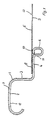
- a flat sheet metal part is formed into a cylindrical tube 14, wherein the flat sheet metal part is pulled by means of clamping jaws 15 over a cylinder 16, whereby the axially extending edges 17 are pressed against each other.
- the heat sealable Coating 7 is located on the inside.
- the axially extending edges 17 are connected by means of a laser beam 19 Cooling plate 18 prevents the coating 7 from being destroyed in the region of the seam 20.
- the pipe 14 is divided into pipe sections as described in DE 43 32 306 A1.
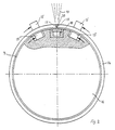
- FIG. 3 shows a pipe section 21 to be formed into a ring part 1 internal coating 7.
- a pipe section 21 is attached to the top molded conical widening 22.
- the drawn section with 23 is designated.
- the cylindrical Section 3 is the cylindrical Section 3 in place. The resulting molded part is shown in FIG. 6.
- the conical widening 21 becomes an annular flange 24 towards the outside formed and the outer flange 2 is formed, which serves to accommodate the can body.
- the inner end is simultaneously folded down, with which the support surface 4 is formed becomes.
- the folded end is rolled up according to Figure 9 and forms the Enrollment 6.
- the cylindrical tube 14 is provided with beads 25, the tube is then divided into pipe sections 21A, the subdivision in each case Area of a bead increase and a bead recess.
- the upper region is flared and the lower region formed radially inwards.
- the subsequent processing steps correspond to the Figures 7 to 9.
Landscapes
- Engineering & Computer Science (AREA)
- Mechanical Engineering (AREA)
- Laser Beam Processing (AREA)
- Rigid Containers With Two Or More Constituent Elements (AREA)
- Piezo-Electric Or Mechanical Vibrators, Or Delay Or Filter Circuits (AREA)
- Closures For Containers (AREA)
- Rolling Contact Bearings (AREA)
- Butt Welding And Welding Of Specific Article (AREA)
- ing And Chemical Polishing (AREA)
Description
- Figur 1:
- einen Schnitt durch einen Dosendeckelrand;
- Figur 2:
- eine Darstellung des Verschweißens eines Blechteils;
- Figuren 3 bis 9:
- eine Darstellung der aufeinanderfolgenden Verfahrensschritte zur Herstellung des Ringteils;
- Figur 10:
- eine Ausführungsvariante der Verarbeitung eines zylindrischen Rohrs und
- Figuren 11 und 12:
- Verfahrensvarianten der in den Figuren 3 bis 6 dargestellten Verfahrensschritte.
Claims (5)
- Verfahren zum Herstellen eines Ringteils (1) aus Blech für einen Dosendeckel mit folgenden Schritten:a) Umformen eines ebenen Blechteils, das an einer Seite eine heißsiegelfähige Beschichtung (7) aufweist, zu einem zylindrischen Rohr (14), bei dem die Beschichtung (7) sich auf der Innenseite befindet,b) Zusammenpressen der axial verlaufenden Ränder (17) des Rohrs (14) zu einem Stumpfstoß und Anpressen einer Kühlplatte (18) gegen die Innenseite des Rohrs (14) längs der axial verlaufenden Ränder (17),c) Herstellen einer Stumpfstoßschweißnaht (20) längs der axial verlaufenden Ränder (17) mittels eines auf die Außenseite der Ränder (17) gerichteten Laserstrahls (19),d) Unterteilen des Rohrs (14) in gleich lange Rohrabschnitte (21),e) konisches Aufweiten des einen Endes jedes Rohrabschnitts (21),f) radiales Einziehen des anderen Endes jedes Rohrabschnitts (21) zur Bildung einer Auflagefläche (4) für eine Aufreißfolie (5) undg) Bördeln des konisch aufgeweiteten Endes zur Bildung eines Außenbördels (2) zur Aufnahme eines Dosenrumpfes.
- Verfahren nach Anspruch 1, dadurch gekennzeichnet, daß vor dem Unterteilen des Rohrs (14) in Rohrabschnitte (21) am Rohr (14) Sicken (25) angebracht werden, die Unterteilung längs der Sickenvertiefungen und längs der Sickenerhöhungen erfolgt und der Bereich der Sickenerhöhung jedes Rohrabschnitts (21A) konisch aufgeweitet wird.
- Verfahren nach Anspruch 1, dadurch gekennzeichnet, daß zwischen der konischen Aufweitung (22) des einen Endes und dem radial nach innen umgeformten anderen Ende ein zylindrischer Abschnitt (3) belassen wird.
- Verfahren nach einem der Ansprüche 1 bis 3, dadurch gekennzeichnet, daß der innen an die Auflagefläche (4) sich anschließende Abschnitt nach unten abgekantet wird und der abgekantete Abschnitt nach oben eingerollt wird.
- Verfahren nach Anspruch 4, dadurch gekennzeichnet, daß das Einrollen auf eine Weise erfolgt, bei welcher die Oberkante der Einrollung (6) in der Ebene der Auflagefläche (4) verläuft.
Applications Claiming Priority (2)
| Application Number | Priority Date | Filing Date | Title |
|---|---|---|---|
| DE10022553A DE10022553C1 (de) | 2000-05-10 | 2000-05-10 | Verfahren zum Herstellen eines Ringteils aus Blech für einen Dosendeckel |
| DE10022553 | 2000-05-10 |
Publications (2)
| Publication Number | Publication Date |
|---|---|
| EP1153840A1 EP1153840A1 (de) | 2001-11-14 |
| EP1153840B1 true EP1153840B1 (de) | 2002-09-11 |
Family
ID=7641299
Family Applications (1)
| Application Number | Title | Priority Date | Filing Date |
|---|---|---|---|
| EP01105859A Expired - Lifetime EP1153840B1 (de) | 2000-05-10 | 2001-03-09 | Verfahren zum Herstellen eines Ringteils aus Blech für einen Dosendeckel |
Country Status (8)
| Country | Link |
|---|---|
| US (1) | US6554556B2 (de) |
| EP (1) | EP1153840B1 (de) |
| JP (1) | JP4541588B2 (de) |
| AT (1) | ATE223844T1 (de) |
| DE (2) | DE10022553C1 (de) |
| DK (1) | DK1153840T3 (de) |
| ES (1) | ES2180522T3 (de) |
| PT (1) | PT1153840E (de) |
Cited By (1)
| Publication number | Priority date | Publication date | Assignee | Title |
|---|---|---|---|---|
| US7506529B2 (en) | 2002-06-27 | 2009-03-24 | Alcan Technology & Management Ltd. | Method for producing a can base and a lever ring |
Families Citing this family (14)
| Publication number | Priority date | Publication date | Assignee | Title |
|---|---|---|---|---|
| ATE310596T1 (de) | 2003-01-16 | 2005-12-15 | Alcan Tech & Man Ltd | Verfahren zur herstellung eines deckelringes für einen dosendeckel |
| EP1559655A1 (de) * | 2004-01-29 | 2005-08-03 | Impress Group B.V. | Behälter und Verfahren zu seiner Herstellung |
| CH703157B1 (de) * | 2004-11-19 | 2011-11-30 | Soudronic Ag | Deckelring sowie damit versehener Deckel. |
| US20080223856A1 (en) * | 2005-03-17 | 2008-09-18 | Soudronic Ag | Tear-Off Lid and Method For Its Manufacture |
| EP1747826A1 (de) | 2005-07-27 | 2007-01-31 | Alcan Technology & Management Ltd. | Deckelring für einen Dosendeckel sowie Verfahren zum Herstellen desselben |
| EP1777165A1 (de) * | 2005-10-20 | 2007-04-25 | Alcan Technology & Management Ltd. | Dosendeckel mit Deckelring und Verschlussmembran |
| DE102006005058A1 (de) | 2006-02-03 | 2007-08-16 | IMPRESS Metal Packaging S.A., Crosmières | Expansionsfähiger Deckel für eine Nahrungsmittel-Dose |
| US9956527B2 (en) | 2010-03-24 | 2018-05-01 | Bionest Technologies Inc. | Membrane filter system |
| SG11201401014RA (en) * | 2011-04-20 | 2014-06-27 | Crown Packaging Technology Inc | Method for forming a metal closure |
| CH709571A1 (de) * | 2014-04-29 | 2015-10-30 | Soudronic Ag | Verfahren und Vorrichtung zur Herstellung von Aufreissdeckeln sowie ein Aufreissdeckel. |
| CH713744A2 (de) * | 2017-04-21 | 2018-10-31 | Soudronic Ag | Verfahren und Vorrichtung zur Herstellung von Aufreissdeckeln sowie ein Aufreissdeckel. |
| KR102449882B1 (ko) * | 2018-02-07 | 2022-10-04 | 삼성디스플레이 주식회사 | 레이저 본딩 장치 |
| CH716413A1 (de) | 2019-07-18 | 2021-01-29 | Soudronic Ag | Verfahren und Vorrichtung zur Herstellung von Aufreissdeckeln sowie Aufreissdeckel. |
| FR3101861B1 (fr) * | 2019-10-14 | 2021-11-12 | Groupe Daucy | Méthode de fabrication d’une boîte de conserve |
Family Cites Families (15)
| Publication number | Priority date | Publication date | Assignee | Title |
|---|---|---|---|---|
| US3669346A (en) * | 1969-07-03 | 1972-06-13 | Pillsbury Co | Quick opening container |
| US3871314A (en) * | 1972-10-20 | 1975-03-18 | Dorn Co V | Method of making folded can ends and folded can end product |
| JPS591493B2 (ja) * | 1975-12-29 | 1984-01-12 | トキコ株式会社 | シリンダタンブノセイケイホウホウ |
| JPS52138051A (en) * | 1976-05-14 | 1977-11-17 | Hideo Yageta | Method of fabricating lap joints |
| US4052949A (en) * | 1976-06-21 | 1977-10-11 | Wescan, Inc. | Method for making easy open container end with protective edges for its severed score |
| FR2442100A2 (fr) * | 1978-11-27 | 1980-06-20 | Saurin Emmanuel | Procede de fabrication de corps tubulaires, notamment de boites de conserves, et dispositif pour l'execution de ce procede |
| JPS57200330U (de) * | 1981-06-09 | 1982-12-20 | ||
| JPS59129423U (ja) * | 1983-02-22 | 1984-08-31 | 山陽ブレ−キ工業株式会社 | 縁曲げ機 |
| JPH0734935B2 (ja) * | 1988-03-10 | 1995-04-19 | 古河電気工業株式会社 | 溶接金属管製造用冷却ロール装置 |
| JPH0336783U (de) * | 1989-08-18 | 1991-04-10 | ||
| DE4332306A1 (de) * | 1993-09-23 | 1995-03-30 | Rasselstein Ag | Verfahren zur Herstellung eines leicht zu öffnenden Dosendeckels aus Blech |
| JPH07155879A (ja) * | 1993-12-06 | 1995-06-20 | Awaji Sangyo Kk | 管継手の製造方法及びそれに使用する揺動加工装置 |
| JPH09239473A (ja) * | 1996-03-05 | 1997-09-16 | Mitsubishi Materials Corp | 陽圧缶およびヒートシール缶蓋 |
| DE19625174B4 (de) * | 1996-06-24 | 2008-05-15 | IMPRESS Metal Packaging S.A., Crosmières | Deckelringfertigung ohne Rondenverschnitt |
| JP3036783U (ja) * | 1996-10-15 | 1997-05-02 | 熊谷テクノス株式会社 | 鋼管接続部のジョイント機構 |
-
2000
- 2000-05-10 DE DE10022553A patent/DE10022553C1/de not_active Expired - Fee Related
-
2001
- 2001-03-09 EP EP01105859A patent/EP1153840B1/de not_active Expired - Lifetime
- 2001-03-09 PT PT01105859T patent/PT1153840E/pt unknown
- 2001-03-09 ES ES01105859T patent/ES2180522T3/es not_active Expired - Lifetime
- 2001-03-09 DK DK01105859T patent/DK1153840T3/da active
- 2001-03-09 DE DE50100023T patent/DE50100023D1/de not_active Expired - Fee Related
- 2001-03-09 AT AT01105859T patent/ATE223844T1/de not_active IP Right Cessation
- 2001-05-01 US US09/846,167 patent/US6554556B2/en not_active Expired - Fee Related
- 2001-05-10 JP JP2001139912A patent/JP4541588B2/ja not_active Expired - Fee Related
Cited By (1)
| Publication number | Priority date | Publication date | Assignee | Title |
|---|---|---|---|---|
| US7506529B2 (en) | 2002-06-27 | 2009-03-24 | Alcan Technology & Management Ltd. | Method for producing a can base and a lever ring |
Also Published As
| Publication number | Publication date |
|---|---|
| EP1153840A1 (de) | 2001-11-14 |
| DE50100023D1 (de) | 2002-10-17 |
| ATE223844T1 (de) | 2002-09-15 |
| PT1153840E (pt) | 2003-01-31 |
| JP2002001469A (ja) | 2002-01-08 |
| JP4541588B2 (ja) | 2010-09-08 |
| US20010041115A1 (en) | 2001-11-15 |
| ES2180522T3 (es) | 2003-02-16 |
| US6554556B2 (en) | 2003-04-29 |
| DE10022553C1 (de) | 2001-07-05 |
| DK1153840T3 (da) | 2002-10-21 |
Similar Documents
| Publication | Publication Date | Title |
|---|---|---|
| EP1153840B1 (de) | Verfahren zum Herstellen eines Ringteils aus Blech für einen Dosendeckel | |
| EP0942794B1 (de) | Verfahren zur herstellung eines formteiles | |
| EP0758565B1 (de) | Verfahren und Vorrichtung zum Herstellen von doppelwandigen Durchbrechungen in Bauteilen nach dem Innenhochdruck-Umform-verfahren sowie ein damit hergestellter Querlenker | |
| DE69628917T2 (de) | Verfahren zum überlappschweissen mittels eines höheren energiedichte aufweisenden strahlungsbündels | |
| DE19846152A1 (de) | Kolben mit Kolbengrundkörper aus geschmiedetem Stahl und einem Kühlkanal | |
| EP0355647A2 (de) | Spundbehälter | |
| EP0281024B1 (de) | Aus Metallblech gefertigter Behälter | |
| EP0882191B1 (de) | Zylinderkopfdichtung mit einer mehrere metallblechlagen aufweisenden dichtungsplatte | |
| EP0200098A2 (de) | Verfahren zur Herstellung eines Behälters aus dünnem Blech, wie dünnerem Feinblech und/oder Feinstblech | |
| DE60203122T2 (de) | Verfahren zur montage eines metallringes, das an einem trägerbund montiert und damit verlötet ist, um die ringförmige kühlleitung eines verbrennungsmotorkolbens zu bilden, und verfahren zur herstellung des rippenmetallringes | |
| DE102015016629A1 (de) | Herstellung eines geschweißten Strukturelements und geschweißtes Strukturelement | |
| DE4232161A1 (de) | Verfahren zum Herstellen eines Hohlkörpers | |
| DE19728276C2 (de) | Verfahren zur Bildung eines Vorformlings, durch das Verfahren hergestellter Vorformling und Verwendung des Vorformlings | |
| DE19750021A1 (de) | Gekühlter Ringträger | |
| EP1705446A1 (de) | Rohr für einen Wärmetauscher | |
| WO2005047024A1 (de) | Mittlere trägereinheit eines achsbrückengehäuses für kraftfahrzeuge und herstellungsverfahren | |
| DE10337859A1 (de) | Verfahren zur Herstellung eines Einfüllstutzens | |
| DE10055527C2 (de) | Dosendeckel | |
| DE4332306A1 (de) | Verfahren zur Herstellung eines leicht zu öffnenden Dosendeckels aus Blech | |
| EP1126937B1 (de) | Verfahren und zwischenprodukt zum herstellen eines hohlkörpers sowie ein durch ein derartiges verfahren hergestellter hohlkörper | |
| DE10130726A1 (de) | Verbindung zwischen sich überlappenden, insbesondere plattenförmigen, Bauteilen, sowie Verfahren und Einrichtung zur Herstellung dieser Verbindung | |
| DE102015009242B4 (de) | Bauteilverbund sowie Verfahren und Vorrichtung zur Herstellung eines solchen Bauteilverbunds | |
| DE19640754B4 (de) | Strahlgeschweißter Verbund eines Karosseriebleches mit einem Rollprofil und Verfahren zu dessen Herstellung | |
| DE102007035014B4 (de) | Verfahren zum Herstellen einer Fügeverbindung | |
| DE10103131C2 (de) | Verfahren zur Herstellung von Hohlkörpern aus zumindest zwei aufeinanderliegenden Platinen |
Legal Events
| Date | Code | Title | Description |
|---|---|---|---|
| PUAI | Public reference made under article 153(3) epc to a published international application that has entered the european phase |
Free format text: ORIGINAL CODE: 0009012 |
|
| AK | Designated contracting states |
Kind code of ref document: A1 Designated state(s): AT BE CH CY DE DK ES FI FR GB GR IE IT LI LU MC NL PT SE TR |
|
| AX | Request for extension of the european patent |
Free format text: AL;LT;LV;MK;RO;SI |
|
| 17P | Request for examination filed |
Effective date: 20011006 |
|
| GRAG | Despatch of communication of intention to grant |
Free format text: ORIGINAL CODE: EPIDOS AGRA |
|
| GRAG | Despatch of communication of intention to grant |
Free format text: ORIGINAL CODE: EPIDOS AGRA |
|
| GRAH | Despatch of communication of intention to grant a patent |
Free format text: ORIGINAL CODE: EPIDOS IGRA |
|
| 17Q | First examination report despatched |
Effective date: 20020502 |
|
| GRAH | Despatch of communication of intention to grant a patent |
Free format text: ORIGINAL CODE: EPIDOS IGRA |
|
| GRAA | (expected) grant |
Free format text: ORIGINAL CODE: 0009210 |
|
| AKX | Designation fees paid |
Free format text: AT BE CH CY DE DK ES FI FR GB GR IE IT LI LU MC NL PT SE TR |
|
| AK | Designated contracting states |
Kind code of ref document: B1 Designated state(s): AT BE CH CY DE DK ES FI FR GB GR IE IT LI LU MC NL PT SE TR |
|
| PG25 | Lapsed in a contracting state [announced via postgrant information from national office to epo] |
Ref country code: IE Free format text: LAPSE BECAUSE OF FAILURE TO SUBMIT A TRANSLATION OF THE DESCRIPTION OR TO PAY THE FEE WITHIN THE PRESCRIBED TIME-LIMIT Effective date: 20020911 Ref country code: TR Free format text: LAPSE BECAUSE OF FAILURE TO SUBMIT A TRANSLATION OF THE DESCRIPTION OR TO PAY THE FEE WITHIN THE PRESCRIBED TIME-LIMIT Effective date: 20020911 |
|
| REF | Corresponds to: |
Ref document number: 223844 Country of ref document: AT Date of ref document: 20020915 Kind code of ref document: T |
|
| REG | Reference to a national code |
Ref country code: GB Ref legal event code: FG4D Free format text: NOT ENGLISH |
|
| REG | Reference to a national code |
Ref country code: CH Ref legal event code: EP |
|
| REG | Reference to a national code |
Ref country code: CH Ref legal event code: NV Representative=s name: LUCHS & PARTNER PATENTANWAELTE |
|
| GBT | Gb: translation of ep patent filed (gb section 77(6)(a)/1977) |
Effective date: 20020911 |
|
| REG | Reference to a national code |
Ref country code: IE Ref legal event code: FG4D Free format text: GERMAN |
|
| REF | Corresponds to: |
Ref document number: 50100023 Country of ref document: DE Date of ref document: 20021017 |
|
| REG | Reference to a national code |
Ref country code: DK Ref legal event code: T3 |
|
| REG | Reference to a national code |
Ref country code: PT Ref legal event code: SC4A Free format text: AVAILABILITY OF NATIONAL TRANSLATION Effective date: 20021205 |
|
| REG | Reference to a national code |
Ref country code: GR Ref legal event code: EP Ref document number: 20020404164 Country of ref document: GR |
|
| REG | Reference to a national code |
Ref country code: ES Ref legal event code: FG2A Ref document number: 2180522 Country of ref document: ES Kind code of ref document: T3 |
|
| PG25 | Lapsed in a contracting state [announced via postgrant information from national office to epo] |
Ref country code: CY Free format text: LAPSE BECAUSE OF FAILURE TO SUBMIT A TRANSLATION OF THE DESCRIPTION OR TO PAY THE FEE WITHIN THE PRESCRIBED TIME-LIMIT Effective date: 20030309 |
|
| ET | Fr: translation filed | ||
| PG25 | Lapsed in a contracting state [announced via postgrant information from national office to epo] |
Ref country code: MC Free format text: LAPSE BECAUSE OF NON-PAYMENT OF DUE FEES Effective date: 20030331 |
|
| REG | Reference to a national code |
Ref country code: IE Ref legal event code: FD4D Ref document number: 1153840E Country of ref document: IE |
|
| PLBE | No opposition filed within time limit |
Free format text: ORIGINAL CODE: 0009261 |
|
| STAA | Information on the status of an ep patent application or granted ep patent |
Free format text: STATUS: NO OPPOSITION FILED WITHIN TIME LIMIT |
|
| 26N | No opposition filed |
Effective date: 20030612 |
|
| REG | Reference to a national code |
Ref country code: CH Ref legal event code: PFA Owner name: RASSELSTEIN GMBH Free format text: RASSELSTEIN HOESCH GMBH#KOBLENZER STRASSE 141#56626 ANDERNACH (DE) -TRANSFER TO- RASSELSTEIN GMBH#KOBLENZER STRASSE 141#56626 ANDERNACH (DE) |
|
| NLT1 | Nl: modifications of names registered in virtue of documents presented to the patent office pursuant to art. 16 a, paragraph 1 |
Owner name: RASSELSTEIN GMBH |
|
| REG | Reference to a national code |
Ref country code: FR Ref legal event code: CD |
|
| PGFP | Annual fee paid to national office [announced via postgrant information from national office to epo] |
Ref country code: DK Payment date: 20080314 Year of fee payment: 8 Ref country code: ES Payment date: 20080124 Year of fee payment: 8 |
|
| PGFP | Annual fee paid to national office [announced via postgrant information from national office to epo] |
Ref country code: FI Payment date: 20080307 Year of fee payment: 8 Ref country code: GB Payment date: 20080128 Year of fee payment: 8 Ref country code: LU Payment date: 20080327 Year of fee payment: 8 Ref country code: NL Payment date: 20080131 Year of fee payment: 8 Ref country code: PT Payment date: 20080118 Year of fee payment: 8 Ref country code: SE Payment date: 20080314 Year of fee payment: 8 |
|
| PGFP | Annual fee paid to national office [announced via postgrant information from national office to epo] |
Ref country code: AT Payment date: 20080313 Year of fee payment: 8 |
|
| PGFP | Annual fee paid to national office [announced via postgrant information from national office to epo] |
Ref country code: CH Payment date: 20080423 Year of fee payment: 8 Ref country code: DE Payment date: 20080506 Year of fee payment: 8 Ref country code: FR Payment date: 20080125 Year of fee payment: 8 |
|
| PGFP | Annual fee paid to national office [announced via postgrant information from national office to epo] |
Ref country code: BE Payment date: 20080304 Year of fee payment: 8 |
|
| PGFP | Annual fee paid to national office [announced via postgrant information from national office to epo] |
Ref country code: IT Payment date: 20080328 Year of fee payment: 8 |
|
| PGFP | Annual fee paid to national office [announced via postgrant information from national office to epo] |
Ref country code: GR Payment date: 20080124 Year of fee payment: 8 |
|
| REG | Reference to a national code |
Ref country code: PT Ref legal event code: MM4A Free format text: LAPSE DUE TO NON-PAYMENT OF FEES Effective date: 20090909 |
|
| BERE | Be: lapsed |
Owner name: *RASSELSTEIN G.M.B.H. Effective date: 20090331 |
|
| PG25 | Lapsed in a contracting state [announced via postgrant information from national office to epo] |
Ref country code: PT Free format text: LAPSE BECAUSE OF NON-PAYMENT OF DUE FEES Effective date: 20090909 Ref country code: AT Free format text: LAPSE BECAUSE OF NON-PAYMENT OF DUE FEES Effective date: 20090309 Ref country code: FI Free format text: LAPSE BECAUSE OF NON-PAYMENT OF DUE FEES Effective date: 20090309 |
|
| REG | Reference to a national code |
Ref country code: CH Ref legal event code: PL |
|
| REG | Reference to a national code |
Ref country code: DK Ref legal event code: EBP |
|
| EUG | Se: european patent has lapsed | ||
| GBPC | Gb: european patent ceased through non-payment of renewal fee |
Effective date: 20090309 |
|
| NLV4 | Nl: lapsed or anulled due to non-payment of the annual fee |
Effective date: 20091001 |
|
| REG | Reference to a national code |
Ref country code: FR Ref legal event code: ST Effective date: 20091130 |
|
| PG25 | Lapsed in a contracting state [announced via postgrant information from national office to epo] |
Ref country code: LI Free format text: LAPSE BECAUSE OF NON-PAYMENT OF DUE FEES Effective date: 20090331 Ref country code: CH Free format text: LAPSE BECAUSE OF NON-PAYMENT OF DUE FEES Effective date: 20090331 Ref country code: DE Free format text: LAPSE BECAUSE OF NON-PAYMENT OF DUE FEES Effective date: 20091001 |
|
| PG25 | Lapsed in a contracting state [announced via postgrant information from national office to epo] |
Ref country code: BE Free format text: LAPSE BECAUSE OF NON-PAYMENT OF DUE FEES Effective date: 20090331 Ref country code: NL Free format text: LAPSE BECAUSE OF NON-PAYMENT OF DUE FEES Effective date: 20091001 |
|
| PG25 | Lapsed in a contracting state [announced via postgrant information from national office to epo] |
Ref country code: DK Free format text: LAPSE BECAUSE OF NON-PAYMENT OF DUE FEES Effective date: 20090331 Ref country code: GB Free format text: LAPSE BECAUSE OF NON-PAYMENT OF DUE FEES Effective date: 20090309 Ref country code: FR Free format text: LAPSE BECAUSE OF NON-PAYMENT OF DUE FEES Effective date: 20091123 |
|
| REG | Reference to a national code |
Ref country code: ES Ref legal event code: FD2A Effective date: 20090310 |
|
| PG25 | Lapsed in a contracting state [announced via postgrant information from national office to epo] |
Ref country code: GR Free format text: LAPSE BECAUSE OF NON-PAYMENT OF DUE FEES Effective date: 20091002 |
|
| PG25 | Lapsed in a contracting state [announced via postgrant information from national office to epo] |
Ref country code: ES Free format text: LAPSE BECAUSE OF NON-PAYMENT OF DUE FEES Effective date: 20090310 |
|
| PG25 | Lapsed in a contracting state [announced via postgrant information from national office to epo] |
Ref country code: IT Free format text: LAPSE BECAUSE OF NON-PAYMENT OF DUE FEES Effective date: 20090309 |
|
| PG25 | Lapsed in a contracting state [announced via postgrant information from national office to epo] |
Ref country code: LU Free format text: LAPSE BECAUSE OF NON-PAYMENT OF DUE FEES Effective date: 20090309 |
|
| PG25 | Lapsed in a contracting state [announced via postgrant information from national office to epo] |
Ref country code: SE Free format text: LAPSE BECAUSE OF NON-PAYMENT OF DUE FEES Effective date: 20090310 |