EP1153798A2 - Dachlastträger-Befestigung - Google Patents
Dachlastträger-Befestigung Download PDFInfo
- Publication number
- EP1153798A2 EP1153798A2 EP01111394A EP01111394A EP1153798A2 EP 1153798 A2 EP1153798 A2 EP 1153798A2 EP 01111394 A EP01111394 A EP 01111394A EP 01111394 A EP01111394 A EP 01111394A EP 1153798 A2 EP1153798 A2 EP 1153798A2
- Authority
- EP
- European Patent Office
- Prior art keywords
- roof
- roof rack
- tensioning
- rails
- clamping
- Prior art date
- Legal status (The legal status is an assumption and is not a legal conclusion. Google has not performed a legal analysis and makes no representation as to the accuracy of the status listed.)
- Granted
Links
Images

Classifications
-
- B—PERFORMING OPERATIONS; TRANSPORTING
- B60—VEHICLES IN GENERAL
- B60R—VEHICLES, VEHICLE FITTINGS, OR VEHICLE PARTS, NOT OTHERWISE PROVIDED FOR
- B60R9/00—Supplementary fittings on vehicle exterior for carrying loads, e.g. luggage, sports gear or the like
- B60R9/04—Carriers associated with vehicle roof
- B60R9/058—Carriers associated with vehicle roof characterised by releasable attaching means between carrier and roof
-
- B—PERFORMING OPERATIONS; TRANSPORTING
- B60—VEHICLES IN GENERAL
- B60R—VEHICLES, VEHICLE FITTINGS, OR VEHICLE PARTS, NOT OTHERWISE PROVIDED FOR
- B60R9/00—Supplementary fittings on vehicle exterior for carrying loads, e.g. luggage, sports gear or the like
- B60R9/04—Carriers associated with vehicle roof
- B60R9/045—Carriers being adjustable or transformable, e.g. expansible, collapsible
Definitions
- the invention relates to a roof rack mounting for a motor vehicle, which on each long side of its roof has a roof rail on which the Roof rack with support feet is seated and fastened.
- a roof rack attachment of the above Art is described for example in DE 90 02 387.0 U1.
- Her roof rails are designed as T-profiles, which over its entire length on the roof of the Motor vehicle sits on it and therefore cannot be reached and in which the roof rack is inserted and without tools using a quick-release lever provided on it can be fixed. It will only one side of the T-profile is gripped by the holding means, so in the event of a head-on collision the danger there is that the roof rack detaches from the roof. Therefore, in others, are realized in practice Roof rack fasteners T-nuts in such T-profiles inserted into which one is on the feet of the roof rack screws provided to the To reliably connect the roof rack with the T-profile.
- the invention is based on the problem of a Roof rack mounting of the type mentioned above to design that even with a possible attachment without tools there is no risk that the roof rack in the event of a frontal impact of the motor vehicle is able to detach itself from the vehicle roof and which does not reach under the railing requires.
- this problem is solved by that the roof rails to intervene by one Clamp of a support leg on at least one On the long side a constriction narrowing its cross section has and that the constriction to limit the horizontal Movability of the clamps running vertically Ribs.
- the roof rails can also function as a cover panel have, if according to another training of the Invention the roof rails the cross section of the welding channel at least largely filled out.
- each roof rail is held by a form fit, if a constriction is provided on each long side and the support feet each one in this constriction have gripping projection.
- the roof rack attachment has a visual effect Particularly advantageous because the roof rack is not installed no openings on the outside of the roof rails or vertical ribs the overall appearance interfere if according to another training of the Invention the clamp of each support leg inside the vehicle provided for the respective roof rails are. In contrast to this one has so far with comparable Roof rack mountings the clamps on the outside intended.
- a structurally simple embodiment of the Invention is that for intervention by the Clamp on one side of the respective roof rails for each clamp is provided with at least one constriction which is approximately the width of the clamp, and that the vertical ribs go through the wall area are formed between two constrictions.
- the Roof load railing several openings for intervention each has a clamp of the roof rack and the vertical ribs through the wall area are formed between two openings.
- the roof rack becomes particularly reliable held on the rail when the clamp on her free end an engaging in the opening, in Has the clamping position projecting upward web.
- the clamping clamp can counteract in the clamping position to lay a particularly large area of the roof rails, if the roof rails at the top of their respective Breakthrough a horizontally leading into their profile Has wall area and the clamping bracket accordingly in the tensioned position with a horizontally running tensioning bar bears against this wall area.
- the clamp is particularly against one large area of the roof rails so that there is a large area Support results if according to another training of the invention, the clamp on the connection their clamping web running horizontally in the clamping position one facing down, against the contour of the constriction has adjacent web area.
- the Clamp also from above against an upper support surface support an opening when the clamp bent twice to reach into the roof rails runs and in addition to their horizontal span and the vertical bar that follows it in parallel has aligned support web, which in Clamping position from above on the wall area of the roof rails sits on.
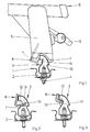
- FIG. 1 shows a partial area of a roof 1 of a motor vehicle with a welding channel 2, which along each long side of the motor vehicle roof 1 runs.
- a roof rail 3 fastened by screws 4.
- the roof rail 3 is supported from above by a support leg 5 a roof rack 6.
- the roof railing 3 is designed as a hollow profile and has at least one in the area of each support leg 5 Opening 7 for a clamp 8 of the support foot 5.
- this clamp 8 is in the open state shown in which the roof rack 6 can lift off the roof 1. If you swivel a clamping lever 9 from the intermediate position shown in Figure 1 further down, then the clamp 8 passes through the opening 7 into the roof rails 3 and thereby clamps the roof rack 6 on the roof rails 3 firmly.
- FIG. 1 also shows that the Roof rails 3 designed as a hollow profile on each long side a longitudinal constriction 10, 11 has.
- the opening 7 is located within the constriction 11 on the inside.
- Figure 2 shows how the clamp 8 in Clamping state engages in the roof rails 3. To do this they extend horizontally in the tensioned position Span 12 and an adjoining, after web 13 directed above, behind a wall region 14 the roof rail 3 engages against which the tensioning web 12 of lies below.
- the Constriction 11 only slightly wider than the clamp 8 and is forward and backward by a rib 15 limited.
- the constriction has the Form of an indentation in the roof rails 3.
- the clamp 8 has only that in this embodiment Tie bar 12 with which it engages in the constriction 11.
- the roof rack 6 slips forward or backward insufficient clamping force in this embodiment prevented by the ribs 15.
- clamp 8 designed so that they are down directed clamping stroke can perform. It is total turned twice and has in addition to her instep 12 and its upward web 13 one horizontally extending support web 16 with which it in the clamping position from above on a support surface 17th of the wall area 14 is tensioned.
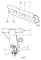
- the embodiment of Figure 7 differs from that according to FIG. 3 in that the tensioning web 12 adjoins a web area 19 directed downwards, which in the tensioned position from the outside the roof rails 3 abut in the region of the constriction 11 and thereby increases the contact area.
- FIG. 8 shows the execution of the roof rails 3 according to the figures 1, 2, 4, 5 and 6. It can be seen that the constriction 11 the roof rails 3 side by side two openings 7, 7a has, which are both dimensioned so that a clamp 8 can intervene in them.
- the wall area between the two Openings 7, 7a form a vertical one Rib 20.
- Figure 9 shows the design of the roof rails 3 according to the embodiment of Figures 3 and 7. Zu see is that the constriction 11 does not have the full Length of the roof rails 3 runs, rather are vertical extending ribs 15, 15a several constrictions 11, 11a, 11b are provided one behind the other, each slightly longer than the individual clamps 8 are wide.
- the Support foot 5 a clamping projection 21, which in the outer Constriction 10 of the roof rails 3 engages. That’s what happens on both sides of the roof rails 3 for a positive fit between the roof rack 6 and the roof rails 3.
Landscapes
- Engineering & Computer Science (AREA)
- Mechanical Engineering (AREA)
- Fittings On The Vehicle Exterior For Carrying Loads, And Devices For Holding Or Mounting Articles (AREA)
- Body Structure For Vehicles (AREA)
- Vehicle Step Arrangements And Article Storage (AREA)
- Particle Accelerators (AREA)
Abstract
Description
- Fig. 1
- eine teilweise geschnitten dargestellte Vorderansicht einer Dachlastträger-Befestigung nach der Erfindung,
- Fig. 2
- bis
- Fig. 7
- Schnitte durch unterschiedliche Ausführungsformen von Dachlastträger-Befestigungen nach der Erfindung,
- Fig. 8
- eine perspektivische Ansicht eines Teilbereiches einer Dachreling nach der Erfindung,
- Fig. 9
- eine perspektivische Ansicht eines Teilbereiches einer zweiten Ausführungsform der Dachreling,
- Fig. 10
- eine teilweise geschnitten dargestellte Vorderansicht einer weiteren Ausführungsform einer DachlastträgerBefestigung nach der Erfindung.
Claims (12)
- Dachlastträger-Befestigung für ein Kraftfahrzeug, welches an jeder Längsseite seines Daches eine Dachreling hat, auf der der Dachlastträger mit Stützfüßen aufsitzt und befestigt ist, dadurch gekennzeichnet, dass die Dachreling (3) zum Eingreifen von jeweils einer Spannklammer (8) eines Stützfußes (5) an zumindest einer Längsseite eine ihren Querschnitt verengende Einschnürung (10, 11) aufweist und dass die Einschnürung (10, 11) zur Begrenzung der horizontalen Verschiebbarkeit der Spannklammern (8) vertikal verlaufende Rippen (15, 20) aufweist.
- Dachlastträger-Befestigung nach Anspruch 1, dadurch gekennzeichnet, dass die Dachreling (3) jeweils in einem Schweißkanal (2) des Daches (1) befestigt ist und nach oben hin aus dem Schweißkanal (2) herausragt.
- Dachlastträger-Befestigung nach den Ansprüchen 1 oder 2, dadurch gekennzeichnet, dass die Dachreling (3) den Querschnitt des Schweißkanals (2) zumindest weitgehend ausfüllt.
- Dachlastträger-Befestigung nach zumindest einem der vorangehenden Ansprüche, dadurch gekennzeichnet, dass an jeder Längsseite eine Einschnürung (10, 11) vorgesehen ist und die Stützfüße (5) jeweils einen in diese Einschnürung (10, 11) greifenden Spannvorsprung (21) aufweisen.
- Dachlastträger-Befestigung nach zumindest einem der vorangehenden Ansprüche, dadurch gekennzeichnet, dass die Spannklammer (8) jedes Stützfußes (5) jeweils fahrzeuginnenseitig zur jeweiligen Dachreling (3) vorgesehen sind.
- Dachlastträger-Befestigung nach den Ansprüchen 4 oder 5, dadurch gekennzeichnet, dass zum Eingreifen durch die Spannklammer (8) an einer Seite der jeweiligen Dachreling (3) für jede Spannklammer (8) zumindest eine Einschnürung (11) vorgesehen ist, welche in etwa die Breite der Spannklammer (8) hat, und dass die vertikal verlaufenden Rippen (15) durch den Wandbereich zwischen zwei Einschnürungen (11) gebildet sind.
- Dachlastträger-Befestigung nach zumindest einem der vorangehenden Ansprüche, dadurch gekennzeichnet, dass die Dachlastreling (3) mehrere Durchbrechungen (7) zum Eingreifen jeweils einer Spannklammer (8) des Dachlastträgers (6) aufweist und die vertikal verlaufenden Rippen durch den Wandbereich zwischen zwei Durchbrechungen (7) gebildet sind.
- Dachlastträger-Befestigung nach Anspruch 7, dadurch gekennzeichnet, dass die Spannklammer (8) an ihrem freien Ende einen in die Durchbrechung (7) eingreifenden, in Spannstellung nach oben ragenden Steg (13) hat.
- Dachlastträger-Befestigung nach Anspruch 7, dadurch gekennzeichnet, dass die Dachreling (3) an der Oberseite ihrer jeweiligen Durchbrechung (7) einen in ihr Profil horizontal hineinführenden Wandbereich (14) hat und die Spannklammer (8) entsprechend in Spannstellung mit einem horizontal verlaufenden Spannsteg (12) gegen diesen Wandbereich (14) anliegt.
- Dachlastträger-Befestigung nach zumindest einem der vorangehenden Ansprüche, dadurch gekennzeichnet, dass die Spannklammer (8) im Anschluss an ihren in Spannstellung horizontal verlaufenden Spannsteg (12) einen nach unten gerichteten, gegen die Kontur der Einschnürung (11) anliegenden Stegbereich (19) hat.
- Dachlastträger-Befestigung nach zumindest einem der vorangehenden Ansprüche, dadurch gekennzeichnet, dass der Dachlastträger (6) zum Erzeugen von nach unten gerichteten Spannhüben ihrer Spannklammern (8) ausgebildet ist und die Dachreling (3) jeweils eine Abstützfläche (17) hat, gegen die in Spannstellung die Spannklammer (8) von oben her mit ihrer Spannkraft aufsitzt.
- Dachlastträger-Befestigung nach Anspruch 11, dadurch gekennzeichnet, dass die Spannklammer (8) zum Eingreifen in die Dachreling (3) zweimal abgebogen verläuft und zusätzlich zu ihrem horizontalen Spannsteg (12) und sich daran anschließendem vertikalen Steg 13 einen parallel zum Spannsteg (13) ausgerichteten Stützsteg (16) hat, der in Spannstellung von oben her auf dem Wandbereich (14) der Dachreling (3) aufsitzt.
Applications Claiming Priority (2)
| Application Number | Priority Date | Filing Date | Title |
|---|---|---|---|
| DE10023526 | 2000-05-13 | ||
| DE10023526A DE10023526A1 (de) | 2000-05-13 | 2000-05-13 | Dachlastträger-Befestigung |
Publications (3)
| Publication Number | Publication Date |
|---|---|
| EP1153798A2 true EP1153798A2 (de) | 2001-11-14 |
| EP1153798A3 EP1153798A3 (de) | 2002-01-02 |
| EP1153798B1 EP1153798B1 (de) | 2005-04-13 |
Family
ID=7641952
Family Applications (1)
| Application Number | Title | Priority Date | Filing Date |
|---|---|---|---|
| EP01111394A Expired - Lifetime EP1153798B1 (de) | 2000-05-13 | 2001-05-10 | Dachlastträger-Befestigung |
Country Status (4)
| Country | Link |
|---|---|
| EP (1) | EP1153798B1 (de) |
| AT (1) | ATE293058T1 (de) |
| DE (2) | DE10023526A1 (de) |
| ES (1) | ES2240275T3 (de) |
Cited By (2)
| Publication number | Priority date | Publication date | Assignee | Title |
|---|---|---|---|---|
| EP1442939A1 (de) * | 2003-02-01 | 2004-08-04 | Adam Opel Ag | Dachreling für ein Fahrzeug und ein Fahrzeugdach |
| EP2011693A1 (de) | 2007-07-03 | 2009-01-07 | Ford Global Technologies, LLC | Dachreling, Montagekomponente und Fahrzeug |
Families Citing this family (4)
| Publication number | Priority date | Publication date | Assignee | Title |
|---|---|---|---|---|
| DE102012014696B4 (de) | 2012-07-25 | 2014-02-13 | Audi Ag | Dachträger für ein Kraftfahrzeug, Verfahren zum Betreiben eines Steuergeräts eines Kraftfahrzeugs sowie entsprechendes Steuergerät |
| DE102012014697B4 (de) * | 2012-07-25 | 2014-02-13 | Audi Ag | Dachträgereinrichtung für ein Kraftfahrzeug sowie entsprechendes Kraftfahrzeug |
| DE102012014703A1 (de) * | 2012-07-25 | 2014-01-30 | Audi Ag | Dachträgereinrichtung für ein Kraftfahrzeug |
| DE102015113689A1 (de) * | 2015-08-18 | 2017-02-23 | Matthias Pleyer | Haltevorrichtung für eine Fahrzeug-Dachlast |
Family Cites Families (11)
| Publication number | Priority date | Publication date | Assignee | Title |
|---|---|---|---|---|
| DE3151404C2 (de) * | 1981-12-24 | 1986-08-28 | Adam Opel AG, 6090 Rüsselsheim | Fahrzeugdach, insbesondere für Personenwagen, mit einer eine Rinne und Halteschiene abdeckenden Blendleiste |
| US5314104A (en) * | 1991-09-26 | 1994-05-24 | Douglas Lee | Auto mount for bicycle rack |
| EP0645283B1 (de) * | 1993-09-15 | 1997-11-19 | Jac Products, Inc. | Lastträger für Kraftfahrzeuge |
| US5385285A (en) * | 1993-12-07 | 1995-01-31 | Jac Products, Inc. | Vehicle article carrier |
| US5577650A (en) * | 1994-12-06 | 1996-11-26 | Advanced Accessory Systems L.L.C. | Split stanchion article carrier with pivoting thumbwheel |
| DE19518949C2 (de) * | 1995-05-23 | 1997-08-14 | Hs Products Ag Systemtechnik U | Vorrichtung zum Befestigen von Lasten an einem Kraftfahrzeug |
| WO1997011863A1 (en) * | 1995-09-28 | 1997-04-03 | Stapleton Craig A | Push button stanchion latch operator with cammed hook |
| WO1997019832A1 (en) * | 1995-11-30 | 1997-06-05 | Advanced Accessory Systems L.L.C. | Split stanchion article carrier |
| US5762247A (en) * | 1996-05-02 | 1998-06-09 | Jac Products, Inc. | Vehicle article carrier |
| US5791536A (en) * | 1996-07-18 | 1998-08-11 | Advanced Accessory Systems Llc | Article carrier assembly |
| US5984155A (en) * | 1997-12-29 | 1999-11-16 | Sportrack Llc | Utility bar assemblies for a roof rack |
-
2000
- 2000-05-13 DE DE10023526A patent/DE10023526A1/de not_active Withdrawn
-
2001
- 2001-05-10 AT AT01111394T patent/ATE293058T1/de not_active IP Right Cessation
- 2001-05-10 ES ES01111394T patent/ES2240275T3/es not_active Expired - Lifetime
- 2001-05-10 EP EP01111394A patent/EP1153798B1/de not_active Expired - Lifetime
- 2001-05-10 DE DE50105882T patent/DE50105882D1/de not_active Expired - Lifetime
Cited By (3)
| Publication number | Priority date | Publication date | Assignee | Title |
|---|---|---|---|---|
| EP1442939A1 (de) * | 2003-02-01 | 2004-08-04 | Adam Opel Ag | Dachreling für ein Fahrzeug und ein Fahrzeugdach |
| EP2011693A1 (de) | 2007-07-03 | 2009-01-07 | Ford Global Technologies, LLC | Dachreling, Montagekomponente und Fahrzeug |
| EP2011694A2 (de) | 2007-07-03 | 2009-01-07 | Ford Global Technologies, LLC | Dachschiene, Klemmelement und Fahrzeug |
Also Published As
| Publication number | Publication date |
|---|---|
| ATE293058T1 (de) | 2005-04-15 |
| ES2240275T3 (es) | 2005-10-16 |
| DE50105882D1 (de) | 2005-05-19 |
| EP1153798B1 (de) | 2005-04-13 |
| DE10023526A1 (de) | 2001-11-15 |
| EP1153798A3 (de) | 2002-01-02 |
Similar Documents
| Publication | Publication Date | Title |
|---|---|---|
| DE19531876C2 (de) | Querträger für die Befestigung des Armaturenbrettes | |
| DE202010000545U1 (de) | Befestigungseinrichtung für einen Holm oder eine Leiste an einem C-Profil | |
| EP2628411B1 (de) | Auszug | |
| DE3613341A1 (de) | Sanitaerer montagerahmen | |
| DE10043656B4 (de) | Mittelkonsole für ein Kraftfahrzeug | |
| EP1153798A2 (de) | Dachlastträger-Befestigung | |
| DE4445403B4 (de) | Kabelgestell und Kabelgestellhalter | |
| EP3241974A1 (de) | Anordnung für eine dichtung, insbesondere für eine auflaufdichtung oder für eine sich selbsttätig absenkende bodendichtung für türen | |
| WO2015180963A1 (de) | Montagevorrichtung | |
| DE4237514A1 (de) | Stütze mit abnehmbarem Stützenkopf | |
| EP0864764A2 (de) | Verbinder zum Verbinden von zwei quer zueinander verlaufenden Hohlprofilstangen sowie Gestell mit solchen Hohlprofilstangen | |
| DE10226972B4 (de) | Befestigungsvorrichtung für einen Handgriff | |
| EP1116830B1 (de) | Montageelement für den Einbau eines Sanitärapparates in ein Tragwerk | |
| DE4333463A1 (de) | Wohnwagen mit einer Befestigungsvorrichtung für Sicherheitsgurte | |
| DE10212990B4 (de) | Dachrahmen eines öffnungsfähigen Fahrzeugdaches | |
| DE19737635C2 (de) | Sitzunterkonstruktion für eine Sitzbank oder einen Einzelsitz in einem Kraftfahrzeug | |
| DE19931040C2 (de) | Verkleidungssystem für eine Wanne, vorzugsweise Badewanne | |
| DE10322289A1 (de) | Seitenschutz für ein Baugerüst | |
| DE102005058333B4 (de) | Vorrichtung zur lösbaren Halterung eines Fahrzeugsitzes an einem Fahrzeugboden | |
| WO2024084064A1 (de) | Halterung für einen geländerpfosten | |
| DE4427132C1 (de) | Halterung zur Befestigung eines Fahrradkorbs auf einem Fahrradgepäckträger | |
| DE19834412A1 (de) | Schiene für Fahrzeugsitze, Fahrzeug mit einem Sitz, der mit einer solchen Schiene ausgestattet ist, und Verankerungshaken für eine solche Schiene | |
| EP0275824A1 (de) | Gerüstelement | |
| DE29704080U1 (de) | Verriegelungsvorrichtung für ein Deckenelement | |
| DE10064408C2 (de) | Fahrzeugsitz, insbesondere Kraftfahrzeugsitz |
Legal Events
| Date | Code | Title | Description |
|---|---|---|---|
| PUAI | Public reference made under article 153(3) epc to a published international application that has entered the european phase |
Free format text: ORIGINAL CODE: 0009012 |
|
| AK | Designated contracting states |
Kind code of ref document: A2 Designated state(s): AT BE CH CY DE DK ES FI FR GB GR IE IT LI LU MC NL PT SE TR |
|
| AX | Request for extension of the european patent |
Free format text: AL;LT;LV;MK;RO;SI |
|
| PUAL | Search report despatched |
Free format text: ORIGINAL CODE: 0009013 |
|
| AK | Designated contracting states |
Kind code of ref document: A3 Designated state(s): AT BE CH CY DE DK ES FI FR GB GR IE IT LI LU MC NL PT SE TR |
|
| AX | Request for extension of the european patent |
Free format text: AL;LT;LV;MK;RO;SI |
|
| 17P | Request for examination filed |
Effective date: 20020626 |
|
| AKX | Designation fees paid |
Free format text: AT BE CH CY DE DK ES FI FR GB GR IE IT LI LU MC NL PT SE TR |
|
| 17Q | First examination report despatched |
Effective date: 20020927 |
|
| GRAP | Despatch of communication of intention to grant a patent |
Free format text: ORIGINAL CODE: EPIDOSNIGR1 |
|
| GRAS | Grant fee paid |
Free format text: ORIGINAL CODE: EPIDOSNIGR3 |
|
| GRAA | (expected) grant |
Free format text: ORIGINAL CODE: 0009210 |
|
| AK | Designated contracting states |
Kind code of ref document: B1 Designated state(s): AT BE CH CY DE DK ES FI FR GB GR IE IT LI LU MC NL PT SE TR |
|
| PG25 | Lapsed in a contracting state [announced via postgrant information from national office to epo] |
Ref country code: NL Free format text: LAPSE BECAUSE OF FAILURE TO SUBMIT A TRANSLATION OF THE DESCRIPTION OR TO PAY THE FEE WITHIN THE PRESCRIBED TIME-LIMIT Effective date: 20050413 Ref country code: FI Free format text: LAPSE BECAUSE OF FAILURE TO SUBMIT A TRANSLATION OF THE DESCRIPTION OR TO PAY THE FEE WITHIN THE PRESCRIBED TIME-LIMIT Effective date: 20050413 Ref country code: IE Free format text: LAPSE BECAUSE OF FAILURE TO SUBMIT A TRANSLATION OF THE DESCRIPTION OR TO PAY THE FEE WITHIN THE PRESCRIBED TIME-LIMIT Effective date: 20050413 |
|
| REG | Reference to a national code |
Ref country code: GB Ref legal event code: FG4D Free format text: NOT ENGLISH |
|
| REG | Reference to a national code |
Ref country code: CH Ref legal event code: EP |
|
| PG25 | Lapsed in a contracting state [announced via postgrant information from national office to epo] |
Ref country code: CY Free format text: LAPSE BECAUSE OF FAILURE TO SUBMIT A TRANSLATION OF THE DESCRIPTION OR TO PAY THE FEE WITHIN THE PRESCRIBED TIME-LIMIT Effective date: 20050510 Ref country code: AT Free format text: LAPSE BECAUSE OF NON-PAYMENT OF DUE FEES Effective date: 20050510 Ref country code: LU Free format text: LAPSE BECAUSE OF NON-PAYMENT OF DUE FEES Effective date: 20050510 |
|
| REG | Reference to a national code |
Ref country code: IE Ref legal event code: FG4D Free format text: LANGUAGE OF EP DOCUMENT: GERMAN |
|
| REF | Corresponds to: |
Ref document number: 50105882 Country of ref document: DE Date of ref document: 20050519 Kind code of ref document: P |
|
| PG25 | Lapsed in a contracting state [announced via postgrant information from national office to epo] |
Ref country code: LI Free format text: LAPSE BECAUSE OF NON-PAYMENT OF DUE FEES Effective date: 20050531 Ref country code: MC Free format text: LAPSE BECAUSE OF NON-PAYMENT OF DUE FEES Effective date: 20050531 Ref country code: CH Free format text: LAPSE BECAUSE OF NON-PAYMENT OF DUE FEES Effective date: 20050531 Ref country code: BE Free format text: LAPSE BECAUSE OF NON-PAYMENT OF DUE FEES Effective date: 20050531 |
|
| GBT | Gb: translation of ep patent filed (gb section 77(6)(a)/1977) |
Effective date: 20050616 |
|
| PG25 | Lapsed in a contracting state [announced via postgrant information from national office to epo] |
Ref country code: SE Free format text: LAPSE BECAUSE OF FAILURE TO SUBMIT A TRANSLATION OF THE DESCRIPTION OR TO PAY THE FEE WITHIN THE PRESCRIBED TIME-LIMIT Effective date: 20050713 Ref country code: DK Free format text: LAPSE BECAUSE OF FAILURE TO SUBMIT A TRANSLATION OF THE DESCRIPTION OR TO PAY THE FEE WITHIN THE PRESCRIBED TIME-LIMIT Effective date: 20050713 Ref country code: GR Free format text: LAPSE BECAUSE OF FAILURE TO SUBMIT A TRANSLATION OF THE DESCRIPTION OR TO PAY THE FEE WITHIN THE PRESCRIBED TIME-LIMIT Effective date: 20050713 |
|
| PG25 | Lapsed in a contracting state [announced via postgrant information from national office to epo] |
Ref country code: PT Free format text: LAPSE BECAUSE OF FAILURE TO SUBMIT A TRANSLATION OF THE DESCRIPTION OR TO PAY THE FEE WITHIN THE PRESCRIBED TIME-LIMIT Effective date: 20050913 |
|
| NLV1 | Nl: lapsed or annulled due to failure to fulfill the requirements of art. 29p and 29m of the patents act | ||
| REG | Reference to a national code |
Ref country code: ES Ref legal event code: FG2A Ref document number: 2240275 Country of ref document: ES Kind code of ref document: T3 |
|
| BERE | Be: lapsed |
Owner name: ADAM OPEL A.G. Effective date: 20050531 |
|
| REG | Reference to a national code |
Ref country code: IE Ref legal event code: FD4D |
|
| REG | Reference to a national code |
Ref country code: CH Ref legal event code: PL |
|
| ET | Fr: translation filed | ||
| PLBE | No opposition filed within time limit |
Free format text: ORIGINAL CODE: 0009261 |
|
| STAA | Information on the status of an ep patent application or granted ep patent |
Free format text: STATUS: NO OPPOSITION FILED WITHIN TIME LIMIT |
|
| 26N | No opposition filed |
Effective date: 20060116 |
|
| BERE | Be: lapsed |
Owner name: *ADAM OPEL A.G. Effective date: 20050531 |
|
| PGFP | Annual fee paid to national office [announced via postgrant information from national office to epo] |
Ref country code: TR Payment date: 20080422 Year of fee payment: 8 |
|
| REG | Reference to a national code |
Ref country code: GB Ref legal event code: 732E Free format text: REGISTERED BETWEEN 20090219 AND 20090225 |
|
| REG | Reference to a national code |
Ref country code: GB Ref legal event code: 732E Free format text: REGISTERED BETWEEN 20090305 AND 20090311 |
|
| REG | Reference to a national code |
Ref country code: GB Ref legal event code: 732E Free format text: REGISTERED BETWEEN 20091029 AND 20091104 |
|
| REG | Reference to a national code |
Ref country code: GB Ref legal event code: 732E Free format text: REGISTERED BETWEEN 20091105 AND 20091111 |
|
| REG | Reference to a national code |
Ref country code: DE Ref legal event code: R081 Ref document number: 50105882 Country of ref document: DE Owner name: GM GLOBAL TECHNOLOGY OPERATIONS LLC (N. D. GES, US Free format text: FORMER OWNER: GM GLOBAL TECHNOLOGY OPERATIONS, INC., DETROIT, US Effective date: 20110323 Ref country code: DE Ref legal event code: R081 Ref document number: 50105882 Country of ref document: DE Owner name: GM GLOBAL TECHNOLOGY OPERATIONS LLC (N. D. GES, US Free format text: FORMER OWNER: GM GLOBAL TECHNOLOGY OPERATIONS, INC., DETROIT, MICH., US Effective date: 20110323 |
|
| PGFP | Annual fee paid to national office [announced via postgrant information from national office to epo] |
Ref country code: GB Payment date: 20120509 Year of fee payment: 12 Ref country code: FR Payment date: 20120608 Year of fee payment: 12 |
|
| PGFP | Annual fee paid to national office [announced via postgrant information from national office to epo] |
Ref country code: IT Payment date: 20120516 Year of fee payment: 12 |
|
| PG25 | Lapsed in a contracting state [announced via postgrant information from national office to epo] |
Ref country code: TR Free format text: LAPSE BECAUSE OF NON-PAYMENT OF DUE FEES Effective date: 20090510 |
|
| GBPC | Gb: european patent ceased through non-payment of renewal fee |
Effective date: 20130510 |
|
| PG25 | Lapsed in a contracting state [announced via postgrant information from national office to epo] |
Ref country code: IT Free format text: LAPSE BECAUSE OF NON-PAYMENT OF DUE FEES Effective date: 20130510 |
|
| REG | Reference to a national code |
Ref country code: FR Ref legal event code: ST Effective date: 20140131 |
|
| PG25 | Lapsed in a contracting state [announced via postgrant information from national office to epo] |
Ref country code: GB Free format text: LAPSE BECAUSE OF NON-PAYMENT OF DUE FEES Effective date: 20130510 |
|
| PG25 | Lapsed in a contracting state [announced via postgrant information from national office to epo] |
Ref country code: FR Free format text: LAPSE BECAUSE OF NON-PAYMENT OF DUE FEES Effective date: 20130531 |
|
| PGFP | Annual fee paid to national office [announced via postgrant information from national office to epo] |
Ref country code: DE Payment date: 20140507 Year of fee payment: 14 Ref country code: ES Payment date: 20140411 Year of fee payment: 14 |
|
| REG | Reference to a national code |
Ref country code: DE Ref legal event code: R119 Ref document number: 50105882 Country of ref document: DE |
|
| PG25 | Lapsed in a contracting state [announced via postgrant information from national office to epo] |
Ref country code: DE Free format text: LAPSE BECAUSE OF NON-PAYMENT OF DUE FEES Effective date: 20151201 |
|
| REG | Reference to a national code |
Ref country code: ES Ref legal event code: FD2A Effective date: 20160629 |
|
| PG25 | Lapsed in a contracting state [announced via postgrant information from national office to epo] |
Ref country code: ES Free format text: LAPSE BECAUSE OF NON-PAYMENT OF DUE FEES Effective date: 20150511 |