EP1153751A2 - Tintenpatrone zur Benutzung in einem Aufzeichnungsgerät - Google Patents
Tintenpatrone zur Benutzung in einem Aufzeichnungsgerät Download PDFInfo
- Publication number
- EP1153751A2 EP1153751A2 EP01107886A EP01107886A EP1153751A2 EP 1153751 A2 EP1153751 A2 EP 1153751A2 EP 01107886 A EP01107886 A EP 01107886A EP 01107886 A EP01107886 A EP 01107886A EP 1153751 A2 EP1153751 A2 EP 1153751A2
- Authority
- EP
- European Patent Office
- Prior art keywords
- ink
- ink pack
- pack
- recording apparatus
- cartridge
- Prior art date
- Legal status (The legal status is an assumption and is not a legal conclusion. Google has not performed a legal analysis and makes no representation as to the accuracy of the status listed.)
- Granted
Links
Images


Classifications
-
- B—PERFORMING OPERATIONS; TRANSPORTING
- B41—PRINTING; LINING MACHINES; TYPEWRITERS; STAMPS
- B41J—TYPEWRITERS; SELECTIVE PRINTING MECHANISMS, i.e. MECHANISMS PRINTING OTHERWISE THAN FROM A FORME; CORRECTION OF TYPOGRAPHICAL ERRORS
- B41J2/00—Typewriters or selective printing mechanisms characterised by the printing or marking process for which they are designed
- B41J2/005—Typewriters or selective printing mechanisms characterised by the printing or marking process for which they are designed characterised by bringing liquid or particles selectively into contact with a printing material
- B41J2/01—Ink jet
- B41J2/17—Ink jet characterised by ink handling
- B41J2/175—Ink supply systems ; Circuit parts therefor
- B41J2/17503—Ink cartridges
- B41J2/17513—Inner structure
Definitions
- the present invention relates to an ink cartridge for an ink-jet recording apparatus, having an ink pack that is formed of flexible material into a flat bag shape, and that is stored in a case forming an outer shell of the cartridge.
- an ink-jet recording apparatus is equipped with an ink-jet recording head which is mounted on a carriage and moved in the widthwise direction of recording paper, and paper feed system for moving the recording paper in the direction orthogonal to the traveling direction of the recording head.
- ink droplets are ejected from the recording head, thus recording the data on the recording paper.
- a recording apparatus of this type supplied for, for example, an office or business purpose, requires use of high-volume ink cartridges.
- a recording apparatus in which ink cartridges are fitted to a cartridge holder provided, for example, to an apparatus main body.
- sub-tanks are disposed on the carriage having the recording head, and the respective sub-tanks are replenished with ink from corresponding ink cartridges by way of ink supply tubes.
- the sub-tanks supply ink to the recording head.
- an ink cartridge to be used in the recording apparatus having the foregoing construction includes a hermitically sealed case constituting an outer shell, and an ink pack which is formed by flexible material, which stores ink therein and which is accommodated in the case.
- the ink pack in the ink cartridge of such a construction is depressed under pressurized air applied to the inside of the case to discharge and supply ink toward the recording head mounted on the carriage.
- the ink filled in the ink pack is diminished in the vicinity of the outlet port of the ink pack.
- the center portions of the ink pack for example, come into close contact with each other to hinder ink flow.
- the user is required to bear higher operating costs in the long term. Further, even at the time of disposal of a cartridge, the load such as treatment of the residual ink or the like is required.
- Such a phenomenon is likely to arise particularly in a construction in which an ink pack is pressurized by the pressurized air applied into a case of the ink cartridge.
- the present invention has been conceived to solve such technical drawbacks.
- the present invention is aimed at providing an ink cartridge which is adapted for use with an ink-jet recording apparatus designed to pressurize an ink pack by pressurized air applied to the inside of a cartridge case, and which can improve the efficiency of use of ink filled in the ink pack.
- the present invention is aimed at providing an ink cartridge which is adapted for use with an ink-jet recording apparatus designed to pressurize an ink pack by pressurized air applied to a case, and mount the flattened ink pack to orient the surfaces thereof, in particular, in substantially a vertical state, and which can improve the efficiency of use of ink filled in the ink pack.
- the present invention is aimed at providing an ink cartridge which is adapted for use with an ink-jet recording apparatus designed to pressurize an ink pack by pressurized air applied to a case, and to mount the flattened ink pack to orient surfaces thereof, in particular, in substantially a horizontal state, and which can improve the efficiency of use of ink filled in the ink pack.
- an ink cartridge for use with a recording apparatus comprising:
- the ink cartridge is constructed such that the case is hermetically formed, and air pressure can be applied from a recording apparatus to the interior of the case to pressurize the ink pack when the ink cartridge is loaded to the recording apparatus.
- the contact prevention member for preventing close contact between interior surfaces of the ink pack, caused by a reduction in the amount of ink stored be formed from genuine material.
- the ink cartridge is loaded to the recording apparatus such that surfaces of the flattened ink pack are oriented in a vertical direction, and the contact prevention member for preventing close contact between interior surfaces of the ink pack is located in a lower position with respect to the direction of gravity.
- the contact prevention member is formed from a single rod member. Further, it is desirable that the contact prevention member formed from the single rod member be fixed on one interior surface of flexible material constituting the ink pack, by heat welding.
- the contact prevention member is formed by bending a single rod member into a substantially-rectangular shape, and arranging the rod member along four sides of the flattened ink pack.
- pressurized air is introduced into the case when the ink cartridge is loaded to the recording apparatus, and the ink filled in the ink pack is let outside when the ink pack receives the pressurized air.
- the contact prevention member formed from genuine material for preventing close contact between the interior surfaces of the ink pack is housed within the ink pack, the presence of the contact prevention member prevents a problem of, for example, clogging in the center portions of the ink pack, which would otherwise be caused when the center portions are brought into close contact with each other as a result of pressurized air acting on the ink pack.
- a void is formed in the area of the ink pack where the contact prevention member is housed, and remaining ink is guided to an outlet port by way of an ink flow passage formed by the void.
- Genuine material for example, a metal rod member or a so-called wire, can be utilized as the contact prevention member.
- the amount of ink remaining in the ink pack can be reduced to as small amount as possible, thus improving the efficiency of use of ink stored in the ink pack.
- the contact prevention member for preventing close contact between interior surfaces of the ink pack is located at least partially in a lower position with respect to the direction of gravity within the ink pack, whereby the ink remaining in the ink pack gathers around the area in the vicinity of the contact prevention member under gravity.
- the residual ink that has gathered around the area in the vicinity of the contact prevention member is guided to the outlet port by way of the ink flow passage formed by the contact prevention member, thus contributing to the efficiency of use of the ink stored in the ink cartridge.
- the contact prevention member formed from a single rod member sufficiently operates, thus effecting substantially no influence on costs for manufacturing ink cartridges.
- the contact prevention member is formed from a single rod member and into a substantially-rectangular shape.
- the rectangular contact prevention member is housed along four sides of the ink pack, there is eliminated a necessity of managing the front and reverse sides of the ink pack during the course of housing the ink pack into the ink cartridge.
- ink remaining in the ink pack can gather in the vicinity of the contact prevention member under gravity.
- An ink cartridge for use with a recording apparatus comprising:
- the ink flow passage is formed by press-forming flexible material constituting the ink pack.
- the ink flow passage formed along the gravity direction lower side of the ink pack is elongated to reach the vicinity of the ink outlet port.
- the ink cartridge is formed such that the case is formed hermetically, and air pressure can be applied from a recording apparatus to the interior of the case to pressurize the ink pack when the ink cartridge is loaded to the recording apparatus.
- the ink cartridge of the second aspect embodied as mentioned above is loaded to the recording apparatus such that surfaces of a flattened ink pack are oriented in a vertical direction, and an ink flow passage bulging outwardly of the ink pack is formed on at least one of interior surfaces of flexible material constituting the ink pack to extend along the gravity direction lower side of the ink pack.
- the ink remaining in the ink pack gathers along and into the ink flow passage formed by the action of gravity.
- the ink gathering in the vicinity of the ink flow passage is guided to the outlet port by way of the ink flow passage, thus improving the efficiency of use of ink stored in the ink cartridge.
- the ink flow passage bulging outwardly and formed on at least one of interior surfaces of flexible material constituting the ink pack can be readily formed, by press-forming flexible material constituting the ink pack. Consequently, no substantial influence is exerted on costs for manufacturing an ink cartridge.
- An ink cartridge for use with a recording apparatus comprising:
- the ink flow passages are formed by press-forming flexible material constituting the ink pack.
- an ink outlet side end of each ink flow passage formed along the respective side of the ink pack is extended to reach the vicinity of the ink outlet port.
- the ink cartridge is formed such that the case is formed hermetically, and air pressure can be applied from a recording apparatus to the inside of the case to pressurize the ink pack when the ink cartridge is loaded to the recording apparatus.
- the ink cartridge of the third aspect embodied as mentioned above is loaded to the recording apparatus such that surfaces of a flattened ink pack are oriented in a horizontal direction, and ink flow passages bulging outwardly are formed on at least one of interior surfaces of flexible material constituting the ink pack to extend along respective sides of the ink pack perpendicular to the side in which the ink outlet port is formed.
- the ink remaining in the ink pack gathers into and along the ink flow passages formed along the respective side edges of the ink pack.
- the ink remaining in the vicinity of the ink flow passages is guided to the outlet port by way of the ink flow passages, thus improving the efficiency of use of ink stored in the ink cartridge.
- the ink flow passages bulging outwardly and formed on at least one of interior surfaces of flexible material constituting the ink pack can be readily formed, by press-forming flexible material constituting the ink pack. Consequently, no substantial influence is exerted on costs for manufacturing an ink cartridge.
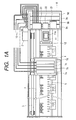
- Fig. 1 is a top view showing an example of an ink-jet recording apparatus capable of using an ink cartridge constructed according to, for example, a first aspect of the present invention.
- reference numeral 1 designates a carriage.
- the carriage 1 is constructed so as to cause reciprocating movement in the longitudinal direction of a paper feed member 5; that is, in the primary scanning direction identical with the widthwise direction of recording paper, while being guided by a scan guide member 4 by way of a timing belt 3 driven by a carriage motor 2.
- an ink-jet recording head 6 to be described later is mounted on the surface of the carriage 1, which surface opposes the paper feed member 5.
- Sub-tanks 7a through 7d for supplying ink to the recording head are mounted on the carriage 1.
- four sub-tanks 7a through 7d are provided so as to correspond to the types of ink and to temporarily store the ink therein.
- the sub-tanks 7a through 7d are constructed such that, for example, black ink, yellow ink, magenta ink, and cyan ink are supplied to the sub-tanks 7a through 7d from corresponding main tanks 9a through 9d through flexible ink supply tubes 10, respectively.
- the main tanks 9a through 9d i.e. ink cartridges, are attached to a cartridge holder 8 provided on the apparatus main body of the recording apparatus.
- each of the main tanks 9a through 9d serving as the ink cartridges has a rectangular and flattened outer shell configuration, and, in case of the recording apparatus embodiment shown in Fig. 1A, is attached to the cartridge holder 8 in such a vertical state that the flattened surface direction of the cartridge is oriented in a perpendicular direction.
- Capping system 11 capable of sealing a nozzle-formed plane of the recording head is disposed in a non-print region (i.e., at the home position) on the travel path of the carriage 1.
- a cap member 11a which is formed from flexible material, such as rubber, that is capable of sealing a nozzle-formed plane of the recording head is attached to the upper surface of the capping system 11.
- the cap member 11a is designed to seal the nozzle-formed plane of the recording head when the carriage 1 is moved to the home position.
- the cap member 11a seals the nozzle-formed plane of the recording head, thereby acting as a cover for preventing drying of nozzle orifices.
- a tube of a suction pump i.e., a tube pump
- negative pressure generated by the suction pump is applied to the recording head, to thereby perform a cleaning operation for causing the recording head to discharge ink under suction.
- Fig. 1B is a perspective view showing an example of an ink jet type recording apparatus with which an ink cartridge according to the present invention, in particular, a second aspect of the present invention, can be suitably used.
- each of ink cartridges (main tanks) 9a through 9d of flattened outer shell configurations is mounted to the cartridge holder 8 in such a longitudinally set state that the flattened surface direction of the cartridge is oriented in a vertical direction.
- Fig. 1C is a perspective view showing an example of an ink jet type recording apparatus with which an ink cartridge according to the present invention, in particular, a third aspect of the present invention can be suitably used.
- each of ink cartridges (main tanks) 9a through 9d of flattened outer shell configurations is mounted to the cartridge holder 8 in such a laterally set state that a direction perpendicular to the flattened surface direction of the cartridge is oriented in a vertical direction, that is, the flattened surface direction of the cartridge is oriented in a horizontal direction.
- the basic constructions of the recording apparatuses shown in Figs. 1B and 1C are substantially the same as that of the recording apparatus shown in Fig. 1A, so that corresponding components or portions are denoted by the same reference numerals, to thereby remove repeated discussion for the components or portions of the recording apparatuses shown in Figs. 1B and 1C.
- Fig. 2 is a schematic drawing showing an ink supply system extending from an ink cartridge to a recording head in the recording apparatus shown in each of Figs. 1A through 1C.
- the ink supply system will now be described by reference to Fig. 2 in conjunction with Figs. 1A through 1C, in which like elements are assigned like reference numerals.
- reference numeral 21 designates an air pressurization pump constituting a pressurization unit.
- the air pressurized by the air pressurization pump 21 is supplied to a pressure regulation valve 22.
- the pressurized air is supplied to the respective main tanks 9a through 9d (the main tanks are designated in Fig. 2 by simply reference numeral 9, and the main tanks will often be described in singular form by use of only reference numeral 9) by way of a pressure detector 23.
- the pressure regulator valve 22 has the function of maintaining the air pressure applied to the respective main tanks 9a through 9d within a predetermined range by releasing pressure when the air pressurized by the air pressurization pump 21 has reached a predetermined pressure level or greater.
- the pressure detector 23 operates so as to detect the air pressurized by the air pressurization pump 21 and control the operation of the air pressurization pump 21. More specifically, when having detected that the air pressurized by the air pressurization pump 21 has reached a predetermined pressure level, the pressure detector 23 stops actuation of the pressurization pump 21 on the basis of the detection result. In contrast, when having detected that the air pressure has fallen below a predetermined pressure level, the pressure detector 23 performs control operation so as to actuate the air pressurization pump 21. By repetition of these operations, the air pressure applied to the main tanks 9a through 9d is maintained within the predetermined range.
- the ink cartridge i.e. the main tank 9
- the outer shell of the main tank 9 is formed hermetically.
- An ink pack 24 which is filled with ink and is formed from resilient material is housed in the main tank 9.
- the space defined by combination of the main tank 9 and the ink pack 24 constitutes a pressure chamber 25, and the pressurized air is supplied to the pressure chamber 25 by way of the pressure detector 23.
- the ink packs 24 housed in the main tanks 9a through 9d are subjected to pressure stemming from the pressurized air, whereby ink flows from the main tanks 9a through 9d to the corresponding sub-tanks 7a through 7d under predetermined pressure.
- the ink pressurized in each of the main tanks 9a through 9d is supplied to the corresponding one of the sub-tanks 7a through 7d mounted on the carriage 1, by way of the corresponding one of ink supply valves 26 and the corresponding one of the ink supply tubes 10 (the sub-tanks are designated in Fig. 2 by use of simply reference numeral 7, and hereinafter the sub-tanks will often be described in singular form by use of simply reference numeral 7).
- a float member 31 is provided within the sub-tank 7, and a permanent magnet 32 is attached to a part of the float member 31.
- Magnetoelectric converter elements 33a and 33b typified by Hall elements are mounted on a board 34, and the board 34 is disposed in close proximity to the side wall of the sub-tank 7.
- the permanent magnet 32 provided on the float member 31 and the Hall elements 33a and 33b constitute ink level detection system.
- an electrical output is produced by the Hall elements 33a and 33b.
- the float member 31 housed in the sub-tank 7 is moved under the force of gravity. In association with this movement, the permanent magnet 32 is also moved in the same direction.
- the electrical output produced by the Hall elements 33a and 33b in association with movement of the permanent magnet 32 can be sensed as the level of the ink stored in the sub-tank 7.
- the ink supply valve 26 is opened.
- the pressurized ink in the main tank 9 is supplied to each corresponding sub-tank 7 whose ink level has lowered.
- the ink supply valve 26 is closed on the basis of the electrical output produced by the Hall elements 33a and 33b.
- ink is intermittently supplied from the main tank 9 to the sub-tank 7, thereby constantly storing substantially a given amount of ink within each sub-tank 7.
- the sub-tank 7 is constructed such that ink is supplied from the sub-tank 7 to the recording head 6 by way of a valve 35 and a tube 36 connected thereto.
- ink droplets are ejected from nozzle orifices 6a formed in the nozzle-formed plane of the recording head 6.
- reference numeral 11 designates the previously-described capping system, and a tube connected to the capping system 11 is connected to an unillustrated suction pump (i.e., a tube pump).
- a suction pump i.e., a tube pump
- Figs. 3 through 5 illustrate an example of an outer shell construction of the ink cartridge (main tank) to be used with the ink-jet recording apparatuses constructed above.
- Fig. 3 shows the overall construction of a lower case which constitutes the outer shell of the main tank.
- This lower case 41 is formed in a flattened box-shaped form. The upper surface of the lower case 41 is opened, and an ink pack 24 filled with ink is housed in the lower case 41.
- a continuous weld surface 42 is formed along the entirety of the peripheral edge of the lower case 41 so as to be located on a substantially-flat single imaginary plane.
- An upright flange section 43 is integrally formed on the peripheral edge of the lower case 41 along the outer periphery of the weld surface 42.
- Fig. 5B is an enlarged view of a corner section designated by B in Fig. 3.
- the upright flange section 43 is formed to prevent splashing of particles, which would otherwise be caused when a director (material to be welded) formed on an upper case is scraped frictionally in a case where the upper case which acts as a second outer shell constituent member is fixed to the lower case 41 shown in Fig. 3 by vibratory welding.
- Grid-shaped reinforcement ribs 44 are formed on the bottom surface of the lower case 41, a surface of the lower case 41 used for defining the pressure chamber 25, to prevent deformation of the lower case 41 caused by air pressure.
- the reinforcement ribs 44 are formed integrally and simultaneously with the lower case 41.
- the upper case is hermetically attached to the lower case 41 to define an internal pressure chamber.
- the grid-shaped reinforcement ribs 44 prevent occurrence of deformation, which would otherwise be caused in the direction orthogonal to the surface of the lower case 41 by the air pressure applied to the internal pressure chamber.
- the present embodiment can also contribute to a reduction in the amount of synthetic resin used for forming a lower case.
- a pair of guide holes 45 are formed on a longitudinal end of the lower case 41.
- the guide holes 45 are fitted to and positioned by a pair of guide pins provided on the cartridge holder of the recording apparatus.
- Fig. 4 shows the overall construction of the upper case constituting the outer shell of the main tank as viewed from its inner surface side.
- This upper case 51 is formed into a flattened box-shaped form, with the center thereof being recessed slightly.
- the upper case 51 is constructed so as to act as a cover of the lower case 41.
- a continuous director (e.g., material to be welded) 52 which is to be frictionally welded upon contact with the weld surface 42 is formed along the periphery of the upper case 51, so as to be located on a substantially-flat single imaginary plane.
- Fig. 5A shows an enlarged view of the corner section designated by A shown in Fig. 4.
- grid-shaped reinforcement ribs 53 are formed on the ceiling lower surface of the upper case 51, i.e. the surface of the upper case 51 defining the pressure chamber 25, to prevent deformation of the surface of the upper case 51, which would otherwise be caused by air pressure.
- the reinforcement ribs 53 are formed integrally and simultaneously with the upper case 51.
- the grid-shaped reinforcement ribs 53 prevent deformation, which would otherwise arise in the direction orthogonal to the surface of the upper case 51 by the air pressure applied to the internal pressure chamber.
- the reinforcement ribs 53 are formed on the ceiling lower surface (i.e. an internal surface) of the upper case 51, thus giving consideration to preventing difficulty in affixing on the surface of a cartridge a label of mark representing the trade name or identification of the cartridge.
- the ink pack 24 preliminarily filled with ink is housed in the lower case 41, and the upper case 51 is then joined to the lower case 41 by the vibration welding, thereby obtaining a final product of the ink cartridge.
- Fig. 6 is a cross-sectional view showing an ink outlet portion in the final product of the ink cartridge. With reference to Fig. 6, an assembly process for the ink cartridge will be described.
- the ink pack 24 which has been filled with ink preliminarily is housed in the lower case 41.
- a plug member 24a which seals the ink pack 24 and constitutes an ink outlet port is exposed outside the lower case 41 by way of an opening section 46 formed in the side end section of the lower case 41.
- an O-ring 56 is abuttingly provided to the opening section 46, and an annular engagement member 57 is pushed and fitted to the opening section 46 from the outside of the lower case 41, so that the plug member 24a of the ink pack 24 can be attached to the opening section 46 of the lower case 41.
- the plug member 24a of the ink pack 24 is attached to the lower case 41 such that the annular engagement member 57 compresses the O-ring 56 fitted to the opening 46. Hence, the space between the opening section 46 formed in the lower case 41 and the plug member 24a of the ink pack 24 is sealed hermetically.
- the upper case 51 is laid on the lower case 41, and the cases 41 and 51 are joined by vibratory welding.
- the peripheral edge of the lower case 41 is supported from below by an unillustrated vibratory welding jig, and the upper case 51 is placed so that the director 52 of the upper case 51 is contacted with the weld surface 42 of the lower case 41.
- the peripheral edge of the upper case 51 is pressed from above by unillustrated another vibratory welding jig, and the vibratory welding jig pressing the upper case 41 operates so as to apply load to the upper case 51 in the direction of gravity and horizontal vibration to the same.
- the director 52 formed on the upper case 51 is slid on the weld surface 42 of the lower case 41 while the load is applied to the director 52.
- the director 52 formed on the upper case 51 is slid on the weld surface 42 of the lower case 41 while the load is applied to the director 52.
- the outer shell which is constructed in the manner as mentioned above and serves as an ink cartridge is hermetically formed, by fused resin of the upper and lower cases 51 and 41. Accordingly, the outer shell can be preferably adopted for use with an ink-jet recording apparatus constructed so as to introduce air pressure into main tanks serving as ink cartridges as described above.
- reference numeral 47 in Fig. 6 designates an air introducing port to which pressurized air generated by pressurizing pump is supplied.
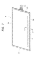
- Fig. 7 shows the structure of the ink pack 24 which is housed in the outer shell case constructed in the manner as mentioned above, and which is used in an ink cartridge according to the first aspect of the present invention.
- Reference numeral 24b designates a heat-welded section in each of the three sides.
- Ink is filled into the ink pack 24 from the remaining one open side of the ink pack 124 formed into the bag. The remaining side is then joined by heat welding to provide the ink pack 124 sealing storing ink therein.
- Reference numeral 24c designates a heat-welded section in the remaining side.
- a contact prevention member 61 formed from genuine or pure material is provided within the ink pack 24 for preventing interior surfaces of the ink pack 24 from being closely contacted with each other.
- the contact prevention member 61 is formed from a single rod member.
- a metal rod member for example, piano wire, or a so-called wire, can be utilized for the contact prevention member 61.
- the contact prevention member 61 is fixed beforehand on the interior surface of one of the sheets constituting the ink pack 24, by heat-welding. More specifically, the contact prevention member 61 is held on the interior surface of the ink pack 24 by the heat-welding used for forming the ink pack 24.
- the contact prevention member 61 is situated in a lower position within the ink pack 24 with respect to the direction of gravity.
- the pressurized air acts on the ink pack 24 so as to make the interior surfaces of the ink pack 24 into close contact with each other.
- the contact prevention member 61 is housed in the ink pack 24 for preventing close contact between the interior surfaces of the ink pack 24, the presence of the contact prevention member 61 prevents a problem of, for example, clogging in the center portions of the ink pack 24, which would otherwise be caused when the center portions of the ink pack are brought into close contact with each other by the pressurized air acting on the ink pack.
- Fig. 9 is an enlarged cross-sectional view showing a part of the ink pack 24, taken along line C-C shown in Fig. 7 as viewed in the direction designated by arrows, in a state in which the remaining ink amount is small.
- the contact prevention member 61 is laid in the longitudinal direction of the ink pack 24. Ink remaining in various locations in the ink pack 24 can be guided to the ink outlet plug member 24a by way of the ink flow passage 62 extending along the contact prevention member 61.
- the ink cartridge is loaded in the recording apparatus such that the surfaces of the ink pack 24 are oriented in the vertical direction, and the contact prevention member 61 is provided so as to be situated in a lower position within the ink pack 24 with respect to the direction of gravity. Hence, the ink remaining in the ink pack 24 gathers around the contact prevention member 61 under gravity. As mentioned above, the remaining ink is guided to the ink outlet plug member 24a by way of the ink flow passage 62 extending along the contact prevention member 61. Consequently, the efficiency of use of ink stored in an ink cartridge can be improved further.
- Fig. 8 shows another embodiment of the ink pack according to the first aspect of the present invention.
- the ink pack shown in Fig. 8 is constructed such that a single rod member bent into a substantially rectangular shape is accommodated within the ink pack 24 along the four sides thereof to serve as the contact prevention member 61.
- the ink pack of this construction is formed in the following manner.
- the rectangular contact prevention member 61 is inserted into the bag-shaped ink pack through one open side.
- ink is filled into the ink pack 24, and finally, the remaining side is bonded by heat welding.
- FIG. 8 eliminates a necessity of managing the front and reverse sides of the ink pack 24 during the course of housing the ink pack 24 into the ink cartridge. As in the previous case, ink remaining in the ink pack 24 can gather in the vicinity of the contact prevention member 61 under gravity.
- the contact prevention member 61 is accommodated in the ink pack 24, which is formed into a flattened bag shape from flexible material, for preventing close contact between interior surfaces of the ink pack 24 caused due to reduction in the amount of ink stored. Hence, ink remaining in the ink pack 24 can be efficiently guided to the ink outlet plug section 24a via the ink flow passage extending along the contact prevention member.
- an ink flow passage can be effectively ensured by the contact prevention member, thus contributing to improvement in the efficiency of use of ink. Further, since the pure or genuine material is used as the contact prevention member, the efficiency of the use of ink can be further improved.
- the ink cartridge according to the second aspect is loaded, for example, to the recording apparatus, which has been described with reference to Fig. 1B, in a vertical state, to provide remarkable effect.
- Figs. 10 through 12 show a first embodiment of an ink pack to be used in an ink cartridge according to the second aspect of the present invention.
- This ink pack is to be housed in an outer shell case similarly to the aforementioned ink pack of the first aspect.
- Fig. 10 is a perspective view showing the ink pack 24 as viewed from one surface thereof.
- Fig. 11 is a rear view of the ink pack 24 as viewed from the reverse surface thereof.
- Fig. 12 is an enlarged cross-sectional view taken along line D-D shown in Figs. 10 and 11 as viewed in the direction designated by arrows.
- the ink pack 24 is also constructed in the same manner as the ink pack 24 used with the ink cartridge described in connection with the first aspect. Corresponding portions of the ink packs 24 are assigned the same reference numerals.
- a bulging section 64 is formed on one of two flexible material sheets constituting the ink pack 23; that is, a flexible material sheet designated by 24e shown in Fig. 12. More specifically, the bulging section 64 bulging toward the exterior surface is arranged so as to continuously extend along the lower side of the ink pack in the gravity direction when the surface direction of the flattened ink pack is oriented substantially in the vertical direction.
- the bulging section 64 is formed on the material sheet 24e by press-molding before the ink pack 24 is bonded by heat-welding to form a bag.
- the bulging section 64 is formed on only one flexible material sheet 24e, as shown in Fig. 12.
- another bulging section may be formed on the other flexible material sheet 24d in the same manner, so as to oppose the bulging section 64 formed on the material sheet 24d.
- the ink pack 24 Since the ink pack 24 is subjected to a pressurized state under the pressure of the pressurized air as described above, when the ink pack 24 becomes close to an ink end (empty) state, the ink pack 24 receives air pressure, so that the two flexible material sheets 24d and 24e constituting the ink pack 24 are brought into close contact with each other as shown in Fig. 2.
- the ink flow passage 62 formed along the lower side of the ink pack in the gravity direction is elongated to the vicinity of the plug member 24a, serving as the ink outlet port, disposed at substantially the central portion of the ink pack end section. Accordingly, the remaining ink gathering around the ink flow passage 62 is guided to the outlet port via the ink flow passage 62.
- the majority of the ink remaining in the ink pack 24 can be guided to the recording apparatus side by the air pressure, with a nominal amount of ink remaining in the ink flow passage 62, thus improving the efficiency of use of ink.
- Fig. 13 shows a second embodiment of an inkpack according to the second aspect of the present invention. Similarly to Fig. 11, Fig. 13 shows the ink pack 24 as viewed from the reverse surface side, and portions corresponding to those which have been already described are denoted by the same reference numerals .
- the cross-section of the ink pack 24 taken along line D-D of Fig. 13 and viewed in the arrow direction is the same as that shown in Fig. 12.
- a structural difference of this embodiment from that shown in Figs. 10 and 11 is that the ink flow passage 62 formed by the bulging portion 64 on the inner surface of the ink pack extends substantially linearly along the lower side in the gravity direction.
- ink in the ink pack close to the ink end state can be guided to the vicinity of the outlet port via the ink flow passage 62 formed by the linear bulging portion 64, and then supplied via the plug member 24a, i.e. the ink outlet portion, to the recording apparatus side.
- an ink pack which is formed from flexible material and into a flattened bag shape is housed in a case constituting the outer shell of the cartridge.
- the ink cartridge is loaded into the recording apparatus such that surfaces of the ink pack are oriented in substantially a vertical direction.
- An ink flow passage bulging outwardly of the ink pack is formed on at least one of flexible material sheets constituting the ink pack, to extend along the ink pack lower side of the gravity direction.
- the residual ink gathering in the vicinity of the ink flow passage can be efficiently guided to the outlet port, thus further improving the efficiency of use of ink stored in the cartridge
- the ink cartridge according to the third aspect is loaded, for example, to the recording apparatus discussed with reference to Fig. 1C, in a horizontal state, to provide remarkable effect.
- Figs. 14 through 15 show an ink pack to be used in the ink cartridge according to the third aspect of the present invention.
- the ink pack is to be housed in an outer shell case similarly to the ink cartridge of the first aspect.
- Fig. 14 is a perspective view showing the ink pack 24 as viewed from one surface thereof.
- Fig. 15 is a rear view of the ink pack 24 as viewed from the reverse surface.
- This ink pack 24 is constructed similarly to the ink pack 24 used in the ink cartridge according to the first aspect, and portions corresponding to the portions which have been already described are denoted by the same reference numerals.
- a cross-section of the ink pack used in the ink cartridge according to the third aspect, taken along line D-D of Figs. 14 and 15 and viewed in the arrow direction is the same as that shown in Fig. 12. That is, a bulging section 64 is formed on one of flexible material sheets constituting the ink pack 24; that is, a flexible material sheet designated by 24e, to bulge outwardly.
- the bulging section 64 is formed on the material sheet 24e by press-molding before the ink pack 24 is bonded by heat-welding to form a bag.
- the embodiment of the third aspect is featured in that the bulging section 64 bulging toward the exterior surface is arranged so as to extend along the longitudinal sides perpendicular to the lateral side in which the plug member 24a is provided as an ink outlet port.
- portions of an ink flow passage 62 formed by the bulging section 64 respectively extend linearly along the longitudinal side edges of the ink pack 24. Further, the ends of portions of the ink flow passage 62 close to the ink outlet port are extended to the area in the vicinity of the ink outlet port, and communicated with each other to form a boomerang-shaped or V-shaped extended portion. Moreover, a bent, central part of the V-shaped extended portion is located in the vicinity of the plug member 24a forming the ink outlet port.
- the ink pack 24 since the ink pack 24 is subjected to a pressurized state under the pressure of the pressurized air, when the ink pack 24 becomes close to an ink end state, the ink pack 24 receives air pressure, so that the two flexible material sheets 24d and 24e constituting the ink pack 24 are brought into close contact with each other as shown in Fig. 12.
- the presence of the bulging section 64 defines the ink flow passage 62 along the interior surface of the ink pack 24. Ink remaining in the ink pack 24 gathers along the ink flow passage (62) linear portions formed by the bulging section 64 along the longitudinal side edges of the ink pack 24.
- the ink remaining in the ink pack 24 is guided, by way of the V-shaped ink flow passage portion, to be supplied from the plug member 24a constituting the ink outlet port to the recording apparatus.
- the majority of the ink remaining in the ink pack 24 can be guided to the recording apparatus by air pressure, with a nominal amount of ink remaining in the ink flow passage 62, thus improving the efficiency of use of ink.
- a pair of bulging section (64) portions are extended to be communicated with each other and to present a V-shaped form.
- a void space is physically formed in the area in which the plug member 24a serving as an ink outlet port is sealed. Hence, the area in the vicinity of the outlet port is unlikely brought into a contact state under air pressure.
- the V-shaped extended portion may be removed from the ink flow passage 62 formed from the pair of bulging sections (64) portions. That is, the ink flow passages 62 are provided independently of each other so as to linearly extend along the respective longitudinal sides of the ink pack 64. Ever. in this case, there can be expected substantially the same effects.
- an ink pack which is formed from flexible material and into a flattened bag shape is housed in a case constituting the outer shell of the cartridge.
- the ink cartridge is loaded into the recording apparatus such that surfaces of the ink pack are oriented in substantially a horizontal direction.
- Ink flow passages bulging outwardly of the ink pack are formed on at least one of flexible material sheets constituting the ink pack, along the respective longitudinal side edges perpendicular to the lateral side in which an ink outlet port is formed. Hence, when the ink cartridge is close to the ink end state, residual ink is guided to either of the ink flow passages.
- the residual ink gathering in the vicinity of the ink flow passages can be efficiently guided to the outlet port, thus further improving the efficiency of use of ink stored in the cartridge
Applications Claiming Priority (6)
| Application Number | Priority Date | Filing Date | Title |
|---|---|---|---|
| JP2000109502A JP2001293882A (ja) | 2000-04-11 | 2000-04-11 | 記録装置用インクカートリッジ |
| JP2000109502 | 2000-04-11 | ||
| JP2000150925 | 2000-05-23 | ||
| JP2000150926A JP2001328272A (ja) | 2000-05-23 | 2000-05-23 | 記録装置用インクカートリッジ |
| JP2000150926 | 2000-05-23 | ||
| JP2000150925A JP2001328271A (ja) | 2000-05-23 | 2000-05-23 | 記録装置用インクカートリッジ |
Publications (3)
| Publication Number | Publication Date |
|---|---|
| EP1153751A2 true EP1153751A2 (de) | 2001-11-14 |
| EP1153751A3 EP1153751A3 (de) | 2002-08-14 |
| EP1153751B1 EP1153751B1 (de) | 2005-10-19 |
Family
ID=27343054
Family Applications (1)
| Application Number | Title | Priority Date | Filing Date |
|---|---|---|---|
| EP01107886A Expired - Lifetime EP1153751B1 (de) | 2000-04-11 | 2001-04-11 | Tintenpatrone zur Benutzung in einem Aufzeichnungsgerät |
Country Status (8)
| Country | Link |
|---|---|
| US (1) | US6848775B2 (de) |
| EP (1) | EP1153751B1 (de) |
| KR (1) | KR100389444B1 (de) |
| CN (2) | CN1285464C (de) |
| AT (1) | ATE307030T1 (de) |
| DE (1) | DE60114079T2 (de) |
| ES (1) | ES2250247T3 (de) |
| HK (1) | HK1042871A1 (de) |
Cited By (2)
| Publication number | Priority date | Publication date | Assignee | Title |
|---|---|---|---|---|
| EP1382451A1 (de) * | 2002-07-18 | 2004-01-21 | Eastman Kodak Company | Tintenpatrone mit mit dem Tintenversorgungssack verbindbarem und lösbarem Gehäuse |
| EP1382452A1 (de) * | 2002-07-18 | 2004-01-21 | Eastman Kodak Company | Einweg Tintensack mit Identifizierungskragen um den Tintenauslass |
Families Citing this family (27)
| Publication number | Priority date | Publication date | Assignee | Title |
|---|---|---|---|---|
| JP4193719B2 (ja) * | 2003-03-05 | 2008-12-10 | セイコーエプソン株式会社 | 液体収容体、液体噴射装置及び液体収容ケース |
| CN1254378C (zh) | 2001-11-12 | 2006-05-03 | 精工爱普生株式会社 | 墨盒 |
| TWI282310B (en) * | 2002-06-28 | 2007-06-11 | Oce Tech Bv | Ink tank |
| TWI296239B (en) * | 2002-06-28 | 2008-05-01 | Oce Tech Bv | Ink tank for ink jet |
| CN100418777C (zh) * | 2003-10-16 | 2008-09-17 | 理想科学工业株式会社 | 墨容器 |
| JP4725182B2 (ja) * | 2005-04-28 | 2011-07-13 | セイコーエプソン株式会社 | 液体供給システムの製造方法及び液体供給システム |
| US7762651B2 (en) * | 2005-06-30 | 2010-07-27 | Hewlett-Packard Development Company, L.P. | Printing device fluid reservoir |
| US8025376B2 (en) * | 2005-09-29 | 2011-09-27 | Brother Kogyo Kabushiki Kaisha | Ink cartridges |
| US20070284930A1 (en) * | 2006-06-09 | 2007-12-13 | Christianson Nicholas M | Chair having removable back or seat cushion assemblies and methods related thereto |
| JP2008006771A (ja) * | 2006-06-30 | 2008-01-17 | Brother Ind Ltd | インク供給装置及びインクジェット記録装置 |
| JP4952093B2 (ja) * | 2006-06-30 | 2012-06-13 | ブラザー工業株式会社 | インクジェット記録装置 |
| JP2008012677A (ja) * | 2006-06-30 | 2008-01-24 | Brother Ind Ltd | 画像記録装置 |
| JP2008006772A (ja) * | 2006-06-30 | 2008-01-17 | Brother Ind Ltd | インク供給装置及びインクジェット記録装置 |
| JP5114878B2 (ja) * | 2006-06-30 | 2013-01-09 | ブラザー工業株式会社 | インクジェット記録装置 |
| JP4935208B2 (ja) * | 2006-07-01 | 2012-05-23 | ブラザー工業株式会社 | 画像記録装置 |
| JP4766011B2 (ja) * | 2007-06-20 | 2011-09-07 | セイコーエプソン株式会社 | 流体噴射装置およびその製造方法 |
| CN101687418B (zh) * | 2007-06-20 | 2012-01-11 | 精工爱普生株式会社 | 流体喷射装置及在该装置中安装流体收容体的方法 |
| US20090027464A1 (en) * | 2007-07-24 | 2009-01-29 | Berg Richard H | Wide format ink cartridge |
| US8297745B2 (en) * | 2007-11-30 | 2012-10-30 | Samsung Electronics Co., Ltd. | Image forming apparatus |
| JP5919737B2 (ja) | 2010-12-08 | 2016-05-18 | セイコーエプソン株式会社 | 液体検出システム、液体容器 |
| CN102615982A (zh) * | 2011-01-31 | 2012-08-01 | 世界网络株式会社 | 墨水槽及墨盒 |
| JP5821611B2 (ja) * | 2011-12-21 | 2015-11-24 | セイコーエプソン株式会社 | 液体収容体 |
| USD722642S1 (en) | 2013-12-13 | 2015-02-17 | Keyence Corporation | Ink bottle for inkjet printer |
| CN107953674B (zh) * | 2016-10-17 | 2020-11-06 | 精工爱普生株式会社 | 液体容纳体 |
| JP7155906B2 (ja) | 2018-11-13 | 2022-10-19 | セイコーエプソン株式会社 | 液体容器および液体噴射装置 |
| CN109720099B (zh) * | 2019-02-28 | 2020-06-02 | 珠海市拓佳科技有限公司 | 墨袋 |
| USD995625S1 (en) | 2020-07-28 | 2023-08-15 | Keyence Corporation | Cartridge for continuous inkjet printer |
Citations (6)
| Publication number | Priority date | Publication date | Assignee | Title |
|---|---|---|---|---|
| US3074104A (en) * | 1957-05-24 | 1963-01-22 | Ici Ltd | Spinning apparatus |
| JPS6154942A (ja) * | 1984-08-27 | 1986-03-19 | Konishiroku Photo Ind Co Ltd | インク貯蔵器 |
| JPS61158460A (ja) * | 1984-12-28 | 1986-07-18 | Konishiroku Photo Ind Co Ltd | インク容器 |
| WO1987004089A1 (en) * | 1985-12-27 | 1987-07-16 | Icab Industrial Coating Ab | An arrangement for a container capable of being filled with material in the form of a powder |
| EP0583154A2 (de) * | 1992-08-12 | 1994-02-16 | Hewlett-Packard Company | Tintendruckregler für Tintenstrahlthermo-Drucker |
| US5325119A (en) * | 1992-08-12 | 1994-06-28 | Hewlett-Packard Company | Variable rate spring ink pressure regulator for a thermal ink jet printer |
Family Cites Families (8)
| Publication number | Priority date | Publication date | Assignee | Title |
|---|---|---|---|---|
| JPS59204566A (ja) * | 1983-05-09 | 1984-11-19 | Ricoh Co Ltd | オンデマンド型インクジエツトプリンタ−におけるインクカ−トリツジのインク袋 |
| JP2558103B2 (ja) * | 1986-07-31 | 1996-11-27 | キヤノン株式会社 | インク供給装置 |
| US5221935A (en) * | 1990-02-15 | 1993-06-22 | Canon Kabushiki Kaisha | Waste ink receiving cartridge and ink recording apparatus using said cartridge |
| SG47827A1 (en) * | 1991-05-27 | 1998-04-17 | Seiko Epson Corp | Ink cartridge for ink jet recording apparatus |
| JPH0752399A (ja) | 1993-08-11 | 1995-02-28 | Canon Inc | インクタンク |
| US6030074A (en) * | 1996-07-15 | 2000-02-29 | Hewlett-Packard Company | Method and apparatus for delivering pressurized ink to a printhead |
| DE19710969C2 (de) * | 1997-03-17 | 2000-11-23 | Pelikan Produktions Ag Egg | Tintenbehälter für einen Tintenstrahl-Drucker oder -Plotter |
| US6158853A (en) * | 1997-06-05 | 2000-12-12 | Hewlett-Packard Company | Ink containment system including a plural-walled bag formed of inner and outer film layers |
-
2001
- 2001-03-16 KR KR10-2001-0013656A patent/KR100389444B1/ko not_active IP Right Cessation
- 2001-04-09 CN CNB2003101033663A patent/CN1285464C/zh not_active Expired - Fee Related
- 2001-04-09 CN CNB011105119A patent/CN1150091C/zh not_active Expired - Fee Related
- 2001-04-11 DE DE60114079T patent/DE60114079T2/de not_active Expired - Lifetime
- 2001-04-11 AT AT01107886T patent/ATE307030T1/de not_active IP Right Cessation
- 2001-04-11 EP EP01107886A patent/EP1153751B1/de not_active Expired - Lifetime
- 2001-04-11 US US09/832,180 patent/US6848775B2/en not_active Expired - Lifetime
- 2001-04-11 ES ES01107886T patent/ES2250247T3/es not_active Expired - Lifetime
-
2002
- 2002-03-27 HK HK02102379A patent/HK1042871A1/xx not_active IP Right Cessation
Patent Citations (6)
| Publication number | Priority date | Publication date | Assignee | Title |
|---|---|---|---|---|
| US3074104A (en) * | 1957-05-24 | 1963-01-22 | Ici Ltd | Spinning apparatus |
| JPS6154942A (ja) * | 1984-08-27 | 1986-03-19 | Konishiroku Photo Ind Co Ltd | インク貯蔵器 |
| JPS61158460A (ja) * | 1984-12-28 | 1986-07-18 | Konishiroku Photo Ind Co Ltd | インク容器 |
| WO1987004089A1 (en) * | 1985-12-27 | 1987-07-16 | Icab Industrial Coating Ab | An arrangement for a container capable of being filled with material in the form of a powder |
| EP0583154A2 (de) * | 1992-08-12 | 1994-02-16 | Hewlett-Packard Company | Tintendruckregler für Tintenstrahlthermo-Drucker |
| US5325119A (en) * | 1992-08-12 | 1994-06-28 | Hewlett-Packard Company | Variable rate spring ink pressure regulator for a thermal ink jet printer |
Non-Patent Citations (2)
| Title |
|---|
| PATENT ABSTRACTS OF JAPAN vol. 010, no. 216 (M-502), 29 July 1986 (1986-07-29) & JP 61 054942 A (KONISHIROKU PHOTO IND CO LTD), 19 March 1986 (1986-03-19) * |
| PATENT ABSTRACTS OF JAPAN vol. 010, no. 360 (M-541), 3 December 1986 (1986-12-03) & JP 61 158460 A (KONISHIROKU PHOTO IND CO LTD), 18 July 1986 (1986-07-18) * |
Cited By (3)
| Publication number | Priority date | Publication date | Assignee | Title |
|---|---|---|---|---|
| EP1382451A1 (de) * | 2002-07-18 | 2004-01-21 | Eastman Kodak Company | Tintenpatrone mit mit dem Tintenversorgungssack verbindbarem und lösbarem Gehäuse |
| EP1382452A1 (de) * | 2002-07-18 | 2004-01-21 | Eastman Kodak Company | Einweg Tintensack mit Identifizierungskragen um den Tintenauslass |
| US6705713B2 (en) | 2002-07-18 | 2004-03-16 | Eastman Kodak Company | Disposable ink assemblage |
Also Published As
| Publication number | Publication date |
|---|---|
| ATE307030T1 (de) | 2005-11-15 |
| EP1153751B1 (de) | 2005-10-19 |
| DE60114079T2 (de) | 2006-07-06 |
| CN1285464C (zh) | 2006-11-22 |
| ES2250247T3 (es) | 2006-04-16 |
| KR20010096615A (ko) | 2001-11-07 |
| US20010038405A1 (en) | 2001-11-08 |
| CN1150091C (zh) | 2004-05-19 |
| KR100389444B1 (ko) | 2003-06-27 |
| DE60114079D1 (de) | 2005-11-24 |
| CN1528593A (zh) | 2004-09-15 |
| HK1042871A1 (en) | 2002-08-30 |
| US6848775B2 (en) | 2005-02-01 |
| CN1317408A (zh) | 2001-10-17 |
| EP1153751A3 (de) | 2002-08-14 |
Similar Documents
| Publication | Publication Date | Title |
|---|---|---|
| US6848775B2 (en) | Ink cartridge for recording apparatus | |
| US8998394B2 (en) | Ink cartridge, and ink-jet recording apparatus using the same | |
| US8083334B2 (en) | Liquid storage container and refilling method using the same | |
| JP5224754B2 (ja) | インクジェット記録装置 | |
| US7052121B2 (en) | Ink cartridge and ink jet printer | |
| JP3817727B2 (ja) | インクジェット式記録装置 | |
| JP4277276B2 (ja) | 液体容器 | |
| JP2002019136A (ja) | 記録装置用インクカートリッジ | |
| JP3767334B2 (ja) | 記録装置用インクカートリッジ | |
| JP5125164B2 (ja) | 流体収容容器 | |
| JP3901626B2 (ja) | インクカートリッジおよびこれを用いるインクジェツト式記録装置 | |
| JP2001328272A (ja) | 記録装置用インクカートリッジ | |
| EP1369244B1 (de) | Tintenpatrone für Tintenstrahlaufzeichnungsvorrichtung | |
| JP3770307B2 (ja) | インクジェット式記録装置 | |
| JP2001212973A (ja) | 記録装置用インクカートリッジ | |
| JP4613983B2 (ja) | 液体貯留手段及び液体噴射装置 | |
| JP2001293882A (ja) | 記録装置用インクカートリッジ | |
| JP2001328271A (ja) | 記録装置用インクカートリッジ | |
| JP2001219575A (ja) | インクジェット式記録装置 | |
| JP5086553B2 (ja) | 液体収容容器 |
Legal Events
| Date | Code | Title | Description |
|---|---|---|---|
| PUAI | Public reference made under article 153(3) epc to a published international application that has entered the european phase |
Free format text: ORIGINAL CODE: 0009012 |
|
| AK | Designated contracting states |
Kind code of ref document: A2 Designated state(s): AT BE CH CY DE DK ES FI FR GB GR IE IT LI LU MC NL PT SE TR |
|
| AX | Request for extension of the european patent |
Free format text: AL;LT;LV;MK;RO;SI |
|
| PUAL | Search report despatched |
Free format text: ORIGINAL CODE: 0009013 |
|
| AK | Designated contracting states |
Kind code of ref document: A3 Designated state(s): AT BE CH CY DE DK ES FI FR GB GR IE IT LI LU MC NL PT SE TR |
|
| AX | Request for extension of the european patent |
Free format text: AL;LT;LV;MK;RO;SI |
|
| 17P | Request for examination filed |
Effective date: 20020830 |
|
| 17Q | First examination report despatched |
Effective date: 20021220 |
|
| AKX | Designation fees paid |
Designated state(s): AT BE CH CY DE DK ES FI FR GB GR IE IT LI LU MC NL PT SE TR |
|
| GRAP | Despatch of communication of intention to grant a patent |
Free format text: ORIGINAL CODE: EPIDOSNIGR1 |
|
| GRAS | Grant fee paid |
Free format text: ORIGINAL CODE: EPIDOSNIGR3 |
|
| GRAA | (expected) grant |
Free format text: ORIGINAL CODE: 0009210 |
|
| AK | Designated contracting states |
Kind code of ref document: B1 Designated state(s): AT BE CH CY DE DK ES FI FR GB GR IE IT LI LU MC NL PT SE TR |
|
| PG25 | Lapsed in a contracting state [announced via postgrant information from national office to epo] |
Ref country code: AT Free format text: LAPSE BECAUSE OF FAILURE TO SUBMIT A TRANSLATION OF THE DESCRIPTION OR TO PAY THE FEE WITHIN THE PRESCRIBED TIME-LIMIT Effective date: 20051019 Ref country code: FI Free format text: LAPSE BECAUSE OF FAILURE TO SUBMIT A TRANSLATION OF THE DESCRIPTION OR TO PAY THE FEE WITHIN THE PRESCRIBED TIME-LIMIT Effective date: 20051019 Ref country code: BE Free format text: LAPSE BECAUSE OF FAILURE TO SUBMIT A TRANSLATION OF THE DESCRIPTION OR TO PAY THE FEE WITHIN THE PRESCRIBED TIME-LIMIT Effective date: 20051019 |
|
| REG | Reference to a national code |
Ref country code: GB Ref legal event code: FG4D |
|
| REG | Reference to a national code |
Ref country code: CH Ref legal event code: EP |
|
| REG | Reference to a national code |
Ref country code: IE Ref legal event code: FG4D |
|
| REF | Corresponds to: |
Ref document number: 60114079 Country of ref document: DE Date of ref document: 20051124 Kind code of ref document: P |
|
| REG | Reference to a national code |
Ref country code: CH Ref legal event code: NV Representative=s name: BOVARD AG PATENTANWAELTE |
|
| PG25 | Lapsed in a contracting state [announced via postgrant information from national office to epo] |
Ref country code: DK Free format text: LAPSE BECAUSE OF FAILURE TO SUBMIT A TRANSLATION OF THE DESCRIPTION OR TO PAY THE FEE WITHIN THE PRESCRIBED TIME-LIMIT Effective date: 20060119 Ref country code: GR Free format text: LAPSE BECAUSE OF FAILURE TO SUBMIT A TRANSLATION OF THE DESCRIPTION OR TO PAY THE FEE WITHIN THE PRESCRIBED TIME-LIMIT Effective date: 20060119 Ref country code: SE Free format text: LAPSE BECAUSE OF FAILURE TO SUBMIT A TRANSLATION OF THE DESCRIPTION OR TO PAY THE FEE WITHIN THE PRESCRIBED TIME-LIMIT Effective date: 20060119 |
|
| PG25 | Lapsed in a contracting state [announced via postgrant information from national office to epo] |
Ref country code: PT Free format text: LAPSE BECAUSE OF FAILURE TO SUBMIT A TRANSLATION OF THE DESCRIPTION OR TO PAY THE FEE WITHIN THE PRESCRIBED TIME-LIMIT Effective date: 20060320 |
|
| PG25 | Lapsed in a contracting state [announced via postgrant information from national office to epo] |
Ref country code: IE Free format text: LAPSE BECAUSE OF NON-PAYMENT OF DUE FEES Effective date: 20060411 |
|
| REG | Reference to a national code |
Ref country code: ES Ref legal event code: FG2A Ref document number: 2250247 Country of ref document: ES Kind code of ref document: T3 |
|
| PG25 | Lapsed in a contracting state [announced via postgrant information from national office to epo] |
Ref country code: MC Free format text: LAPSE BECAUSE OF NON-PAYMENT OF DUE FEES Effective date: 20060430 |
|
| ET | Fr: translation filed | ||
| REG | Reference to a national code |
Ref country code: HK Ref legal event code: GR Ref document number: 1042871 Country of ref document: HK |
|
| PLBE | No opposition filed within time limit |
Free format text: ORIGINAL CODE: 0009261 |
|
| STAA | Information on the status of an ep patent application or granted ep patent |
Free format text: STATUS: NO OPPOSITION FILED WITHIN TIME LIMIT |
|
| 26N | No opposition filed |
Effective date: 20060720 |
|
| REG | Reference to a national code |
Ref country code: IE Ref legal event code: MM4A |
|
| PG25 | Lapsed in a contracting state [announced via postgrant information from national office to epo] |
Ref country code: LU Free format text: LAPSE BECAUSE OF NON-PAYMENT OF DUE FEES Effective date: 20060411 Ref country code: TR Free format text: LAPSE BECAUSE OF FAILURE TO SUBMIT A TRANSLATION OF THE DESCRIPTION OR TO PAY THE FEE WITHIN THE PRESCRIBED TIME-LIMIT Effective date: 20051019 |
|
| PG25 | Lapsed in a contracting state [announced via postgrant information from national office to epo] |
Ref country code: CY Free format text: LAPSE BECAUSE OF FAILURE TO SUBMIT A TRANSLATION OF THE DESCRIPTION OR TO PAY THE FEE WITHIN THE PRESCRIBED TIME-LIMIT Effective date: 20051019 |
|
| REG | Reference to a national code |
Ref country code: CH Ref legal event code: PFA Owner name: SEIKO EPSON CORPORATION Free format text: SEIKO EPSON CORPORATION#4-1, NISHI-SHINJUKU 2-CHOME#SHINJUKU-KU, TOKYO 163-0811 (JP) -TRANSFER TO- SEIKO EPSON CORPORATION#4-1, NISHI-SHINJUKU 2-CHOME#SHINJUKU-KU, TOKYO 163-0811 (JP) |
|
| PGFP | Annual fee paid to national office [announced via postgrant information from national office to epo] |
Ref country code: CH Payment date: 20120412 Year of fee payment: 12 Ref country code: DE Payment date: 20120425 Year of fee payment: 12 Ref country code: NL Payment date: 20120425 Year of fee payment: 12 |
|
| PGFP | Annual fee paid to national office [announced via postgrant information from national office to epo] |
Ref country code: GB Payment date: 20120411 Year of fee payment: 12 Ref country code: FR Payment date: 20120504 Year of fee payment: 12 |
|
| PGFP | Annual fee paid to national office [announced via postgrant information from national office to epo] |
Ref country code: IT Payment date: 20120418 Year of fee payment: 12 |
|
| PGFP | Annual fee paid to national office [announced via postgrant information from national office to epo] |
Ref country code: ES Payment date: 20120424 Year of fee payment: 12 |
|
| REG | Reference to a national code |
Ref country code: NL Ref legal event code: V1 Effective date: 20131101 |
|
| REG | Reference to a national code |
Ref country code: CH Ref legal event code: PL |
|
| GBPC | Gb: european patent ceased through non-payment of renewal fee |
Effective date: 20130411 |
|
| PG25 | Lapsed in a contracting state [announced via postgrant information from national office to epo] |
Ref country code: LI Free format text: LAPSE BECAUSE OF NON-PAYMENT OF DUE FEES Effective date: 20130430 Ref country code: CH Free format text: LAPSE BECAUSE OF NON-PAYMENT OF DUE FEES Effective date: 20130430 Ref country code: GB Free format text: LAPSE BECAUSE OF NON-PAYMENT OF DUE FEES Effective date: 20130411 Ref country code: DE Free format text: LAPSE BECAUSE OF NON-PAYMENT OF DUE FEES Effective date: 20131101 |
|
| REG | Reference to a national code |
Ref country code: FR Ref legal event code: ST Effective date: 20131231 |
|
| REG | Reference to a national code |
Ref country code: DE Ref legal event code: R119 Ref document number: 60114079 Country of ref document: DE Effective date: 20131101 |
|
| PG25 | Lapsed in a contracting state [announced via postgrant information from national office to epo] |
Ref country code: IT Free format text: LAPSE BECAUSE OF NON-PAYMENT OF DUE FEES Effective date: 20130411 Ref country code: FR Free format text: LAPSE BECAUSE OF NON-PAYMENT OF DUE FEES Effective date: 20130430 Ref country code: NL Free format text: LAPSE BECAUSE OF NON-PAYMENT OF DUE FEES Effective date: 20131101 |
|
| REG | Reference to a national code |
Ref country code: ES Ref legal event code: FD2A Effective date: 20140912 |
|
| PG25 | Lapsed in a contracting state [announced via postgrant information from national office to epo] |
Ref country code: ES Free format text: LAPSE BECAUSE OF NON-PAYMENT OF DUE FEES Effective date: 20130412 |