EP1153593B1 - Vorrichtung zum entfernen von fehlerhaften Kapseln - Google Patents
Vorrichtung zum entfernen von fehlerhaften Kapseln Download PDFInfo
- Publication number
- EP1153593B1 EP1153593B1 EP00303852A EP00303852A EP1153593B1 EP 1153593 B1 EP1153593 B1 EP 1153593B1 EP 00303852 A EP00303852 A EP 00303852A EP 00303852 A EP00303852 A EP 00303852A EP 1153593 B1 EP1153593 B1 EP 1153593B1
- Authority
- EP
- European Patent Office
- Prior art keywords
- capsule
- drum
- cap
- transport
- Prior art date
- Legal status (The legal status is an assumption and is not a legal conclusion. Google has not performed a legal analysis and makes no representation as to the accuracy of the status listed.)
- Expired - Lifetime
Links
Images


Classifications
-
- G—PHYSICS
- G07—CHECKING-DEVICES
- G07F—COIN-FREED OR LIKE APPARATUS
- G07F17/00—Coin-freed apparatus for hiring articles; Coin-freed facilities or services
- G07F17/0092—Coin-freed apparatus for hiring articles; Coin-freed facilities or services for assembling and dispensing of pharmaceutical articles
-
- A—HUMAN NECESSITIES
- A61—MEDICAL OR VETERINARY SCIENCE; HYGIENE
- A61J—CONTAINERS SPECIALLY ADAPTED FOR MEDICAL OR PHARMACEUTICAL PURPOSES; DEVICES OR METHODS SPECIALLY ADAPTED FOR BRINGING PHARMACEUTICAL PRODUCTS INTO PARTICULAR PHYSICAL OR ADMINISTERING FORMS; DEVICES FOR ADMINISTERING FOOD OR MEDICINES ORALLY; BABY COMFORTERS; DEVICES FOR RECEIVING SPITTLE
- A61J3/00—Devices or methods specially adapted for bringing pharmaceutical products into particular physical or administering forms
- A61J3/07—Devices or methods specially adapted for bringing pharmaceutical products into particular physical or administering forms into the form of capsules or similar small containers for oral use
- A61J3/071—Devices or methods specially adapted for bringing pharmaceutical products into particular physical or administering forms into the form of capsules or similar small containers for oral use into the form of telescopically engaged two-piece capsules
- A61J3/074—Filling capsules; Related operations
-
- B—PERFORMING OPERATIONS; TRANSPORTING
- B65—CONVEYING; PACKING; STORING; HANDLING THIN OR FILAMENTARY MATERIAL
- B65G—TRANSPORT OR STORAGE DEVICES, e.g. CONVEYORS FOR LOADING OR TIPPING, SHOP CONVEYOR SYSTEMS OR PNEUMATIC TUBE CONVEYORS
- B65G47/00—Article or material-handling devices associated with conveyors; Methods employing such devices
- B65G47/22—Devices influencing the relative position or the attitude of articles during transit by conveyors
- B65G47/24—Devices influencing the relative position or the attitude of articles during transit by conveyors orientating the articles
- B65G47/244—Devices influencing the relative position or the attitude of articles during transit by conveyors orientating the articles by turning them about an axis substantially perpendicular to the conveying plane
-
- B—PERFORMING OPERATIONS; TRANSPORTING
- B65—CONVEYING; PACKING; STORING; HANDLING THIN OR FILAMENTARY MATERIAL
- B65G—TRANSPORT OR STORAGE DEVICES, e.g. CONVEYORS FOR LOADING OR TIPPING, SHOP CONVEYOR SYSTEMS OR PNEUMATIC TUBE CONVEYORS
- B65G47/00—Article or material-handling devices associated with conveyors; Methods employing such devices
- B65G47/22—Devices influencing the relative position or the attitude of articles during transit by conveyors
- B65G47/24—Devices influencing the relative position or the attitude of articles during transit by conveyors orientating the articles
- B65G47/256—Devices influencing the relative position or the attitude of articles during transit by conveyors orientating the articles removing incorrectly orientated articles
-
- G—PHYSICS
- G07—CHECKING-DEVICES
- G07F—COIN-FREED OR LIKE APPARATUS
- G07F11/00—Coin-freed apparatus for dispensing, or the like, discrete articles
- G07F11/02—Coin-freed apparatus for dispensing, or the like, discrete articles from non-movable magazines
- G07F11/04—Coin-freed apparatus for dispensing, or the like, discrete articles from non-movable magazines in which magazines the articles are stored one vertically above the other
- G07F11/16—Delivery means
- G07F11/165—Delivery means using xyz-picker or multi-dimensional article picking arrangements
- G07F11/1657—Delivery means using xyz-picker or multi-dimensional article picking arrangements the picking arrangements using suction
-
- Y—GENERAL TAGGING OF NEW TECHNOLOGICAL DEVELOPMENTS; GENERAL TAGGING OF CROSS-SECTIONAL TECHNOLOGIES SPANNING OVER SEVERAL SECTIONS OF THE IPC; TECHNICAL SUBJECTS COVERED BY FORMER USPC CROSS-REFERENCE ART COLLECTIONS [XRACs] AND DIGESTS
- Y10—TECHNICAL SUBJECTS COVERED BY FORMER USPC
- Y10S—TECHNICAL SUBJECTS COVERED BY FORMER USPC CROSS-REFERENCE ART COLLECTIONS [XRACs] AND DIGESTS
- Y10S53/00—Package making
- Y10S53/90—Capsules
Definitions
- the present invention relates to a capsule transport arrangement with a defective capsule removing mechanism for removing (where capsules are accommodated and held in capsule pockets in a capsule filling machine for transportation, a capsule sealing machine or a capsule appearance inspection apparatus) a coupling defective capsule whose cap and body are separate from each other from a capsule pocket, and a defective capsule removing mechanism for removing, when capsules in a horizontally lying state wherein the cap side is directed in a fixed direction are accommodated in and transported by capsule pockets, a capsule in a reversely horizontally lying state wherein the cap side is directed in the reverse direction.
- capsules empty capsules or filled capsule products supplied successively are accommodated into and transported in capsule pockets, and while they are transported, filling of a contents substance is performed, band sealing is performed, or an appearance inspection is performed.
- Assembled capsules are conventionally elongate, with a generally cylindrical mid-section and rounded ends, and with an intermediate cross-sectional step at the transition from the body to the cap which is slightly larger so as to fit over it.
- the apparatus mentioned includes a capsule supplying apparatus which stably transports capsules from a hopper or the like to the filling mechanism section, band sealing mechanism section or inspection mechanism section and controls the direction of all of the capsules, supplied at random, to a state wherein they are directed in a fixed direction as they are transported; i.e. they are uniformly oriented.
- the capsule filling machine is constructed such that empty capsules whose caps and bodies are temporarily coupled to each other are transported usually in an erected state wherein the cap is directed upwardly. While the empty capsules are transported, they are separated into the caps and the bodies and the contents substance is filled into the bodies. Then the caps and bodies are coupled to each other again to produce filled capsule products. Therefore, a capsule supplying section is required for stably supplying empty capsules, supplied initially at random from a hopper or the like, to the filling mechanism section while controlling the posture of each empty capsule to an erected state wherein the cap is directed upwardly.
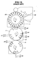
- a supplying mechanism as shown in FIG. 13 is known; see e.g. US-A-4 959 943 and JP-A-1994/298201 . It uses three transporting drums: a supplying drum 1, a direction controlling drum 2 and a feeding drum 3. Capsules are successively transferred and transported among the drums, and while they are transported, the capsules which are supplied at random are controlled in posture to an erected state wherein the cap is directed upwardly. In the following, the supplying mechanism is described briefly.
- the "upward/downward” directions of an empty capsule held on a drum-type transporting unit are upward/downward directions where the outer periphery side of the drum is represented as upward while the center side is represented as downward, and the "erected state” signifies a state wherein the empty capsule is held along a diametral direction of the drum with the cap positioned on the outer periphery side of the drum and with the body directed to the center side of the drum.
- the "inverted state” signifies a state wherein the empty capsule is held along a diametral direction of the drum with the body positioned on the outer periphery side of the drum and with the cap directed toward the center side of the drum
- the "vertically standing state” signifies a state wherein the empty capsule is held along a diametral direction of the drum irrespective of the directions of the cap and the body.
- reference numeral 1 in FIG. 13 denotes a supplying drum on which a large number of supply pockets for accommodating empty capsules AB, each composed of a cap A and a body B temporarily coupled to each other in a vertically standing state, are formed in a row along a circumferential direction.
- the supplying drum 1 accommodates and holds empty capsules supplied at random from a hopper h in an upright standing state in the supply pockets 11 to transport the empty capsules, and transfers the empty capsules to direction controlling pockets 21 of the direction controlling drum 2.
- Each of the direction controlling pockets 21 is composed of an upper portion 211 capable of accommodating an empty capsule in a horizontally lying state, and a bottom portion 212 communicated with an end portion of the upper portion 211 and allowing only the body of a capsule to enter.
- an empty capsule AB' introduced into a direction controlling pocket 21 with the cap A side directed forwardly cannot enter the bottom portion 212, but is accommodated once in the direction controlling pocket 21 in an inverted state wherein the body B side thereof projects from an outer circumferential face of the direction controlling drum 2. Then, as the direction controlling drum 2 rotates, the projecting body B portion of the empty capsule AB' is in contact with a direction controlling guide member 22 by which it is horizontally laid down, so that the empty capsule AB' is accommodated in the upper portion 211 of the direction controlling pocket 21 in a horizontally lying state wherein the cap A is directed in the direction of rotation of the direction controlling drum 2. The empty capsule AB' is transported in this state. Then, such empty capsules AB in an erected state and the empty capsules AB' in a horizontally lying state are transferred to feeding pockets 31 of the feeding drum 3.
- the feeding pockets 31 of the feeding drum 3 are adapted to accommodate empty capsules in an erected state.
- the empty capsules AB accommodated in an erected state in the direction controlling pockets 21 enter as they are into the feeding pockets 31 with the cap A side directed forwardly and are accommodated into the feeding pockets 31 in an inverted state.
- the empty capsules AB' accommodated in a horizontally lying state in the upper portions 211 of the direction controlling pocket 21 are in a horizontally lying state wherein the cap A is directed forwardly in the direction of rotation, they enter the feeding pockets 31 with the cap A side directed forwardly so that they are accommodated into the feeding pockets 31 in an inverted state. In this manner, all empty capsules accommodated in the feeding pockets 31 are brought into an inverted state.
- each empty capsule AB is composed of the cap A and the body B which are temporarily coupled to each other, that they are liable to be separated from each other and are sometimes separated from each other when empty capsules AB are supplied into the hopper h or moved in the hopper h.
- separate caps A and bodies B of empty capsules AB may possibly be present in the hopper h. If such a cap A or a body B as described above by itself is accommodated in a supply pocket 11 of the supplying drum 1, then when it is supplied to the capsule filling mechanism section past the direction controlling drum 2 and the feeding drum 3, this gives rise to various problems at various sections. Also there is the possibility that a cap A or body B in a separate state may be mixed with filled capsule products as final products.
- an empty capsule AB is transferred from a supply pocket 11 of the supplying drum 1 to a direction-controlling pocket 21 of the direction controlling drum 2, even if it is kept in an erected state upon entering the direction controlling pocket 21 with the body B side directed forwardly, it sometimes occurs by some reason that the body B portion thereof does not enter the bottom portion 212 of the direction controlling pockets 21 but the empty capsule AB is accommodated into the upper portion 211 of the direction controlling pocket 21 in a reversely horizontally lying state, with the body B directed in the direction of rotation.
- the empty capsule AB is brought into a state wherein the cap A portion thereof projects from the circumferential face of the drum while the empty capsule AB is in an erected state with the cap A directed upwardly, and therefore is horizontally laid down by the direction controlling guide member 22 into a reversely horizontally lying state with the body B directed in the direction of rotation. If such a reversely horizontally lying capsule as described above is transferred to a feeding pocket 31 of the feeding drum 3 with the body B side directed forwardly, then this causes an empty capsule in an erected state with the cap A directed upwardly to be mixed in empty capsules held on the feeding drum 3 on which all empty capsules must be in an inverted state with the body B side directed upwardly. If the reversely horizontally lying capsule is supplied to the capsule filling section, then there is the possibility that the contents substance may not be filled into the empty capsule, and the capsule may be mixed with filled capsules as final products while it remains empty.
- US-A-4500012 describes capsule handling apparatus providing for ejection of misoriented capsules. Capsules are received in elongate recesses on the carrier drum. The recesses have an escape passage at one end and a retaining ridge part-way along. Misoriented capsules, lying in their recesses with the cap end towards the escape passage, are removed by a clearing force from a rotary brush acting towards the escape passage. With correctly-oriented capsules the edge of the cap catches behind the retaining ridge so that they are not removed by the brush.
- US-A-4091600 also describes an arrangement for orienting an initially random supply of capped empty capsules.
- a rotating carrier drum has a series of entrance holes around its circumference. Once in these holes, the capsules come into contact with direction arranging pieces which extend into grooves between an inner and outer ring of the drum. According to their initial orientation, capsules are received in either the inner or outer ring of the drum. Subsequently they are turned by a pusher to match their orientations.
- a capsule carrier system having a removing arrangement for defective capsules wherein a reverse defective capsule, and optionally also a coupling defective capsule (a body or cap by itself), can be discharged and removed with certainty by comparatively simple means.
- the present invention provides a capsule transport arrangement for transporting capsules which have a cap coupled to a body, the cap having a larger diameter than the body; the transport arrangement comprising a transport body having a capsule pocket opening on an outward face thereof and shaped to accommodate a said capsule lying along the outer face for transport along a transport path; characterised in that one end of the capsule pocket is a cap gripping portion having a reduced width wider than the capsule body diameter but less than the capsule cap diameter whereby a reverse defective capsule, namely one lying in the pocket with its cap towards said end, is retained in the pocket by the cap gripping portion, and in that said outer face of the transport body has a lifter groove which traverses the pocket, preferably at least at the cap gripping portion thereof, and the arrangement comprises a lifter element operable in said groove at a reverse defective removal location to dislodge any reverse defective capsule retained therein.
- the capsule transport arrangement may have a transfer location at which a capsule properly accommodated in said pocket is removed from said pocket and transferred to a subsequent processing stage, whereas a retained reverse defective capsule goes past the transfer location without being removed there and is subsequently removed at the reverse defective removal location.
- the lifter element may be an inclined scraper element which projects into the lifter groove.
- the capsule pocket may have an upper portion adjacent said outer face which provides said accommodation of a capsule lying along the outer face, and a lower portion extending down into the transport body from one end of the upper portion and dimensioned to admit only the body end of a capsule for transport in an upright condition.
- the capsule transport arrangement may also have a guide cam member inclined across the transport path adjacent said outer face of the transport body to deflect any capsule projecting upright and body-outwards down into said upper portion of the pocket to lie along the outer face.
- the transport body may be a rotatable drum.
- a defective capsule removing method for removing, when a capsule is accommodated and held in a horizontally lying state with a cap side thereof directed in a fixed direction in a capsule pocket formed on an outer circumferential face of a transport drum being capable of accommodating a capsule in a horizontally lying state and is transported by rotation of the drum and then the capsule is discharged from the capsule pocket at a predetermined angle of rotation to be transferred to a different transporting unit or the like, a reverse defective capsule accommodated in the capsule pocket in a reversely horizontally lying state with the cap side directed in the reverse direction is removed to prevent a reverse defective capsule directed in the opposite direction from being mixed in a group of capsules to be transferred to the different transporting unit or the like, characterized in that when a capsule in the reversely horizontally laid state with the cap directed in the reverse direction is accommodated into the capsule pocket, one end side of the capsule pocket in which a body side of a capsule is to be accommodated is formed as a cap
- the defective capsule removing mechanism discharges and removes, when a capsule is accommodated and held in a horizontally lying state with a cap side thereof directed in the fixed direction in the capsule pocket formed on the outer circumferential face of the transport drum and is transported and then discharged at the predetermined angle of rotation and transferred to the different transporting unit or the like, a reverse defective capsule accommodated in the capsule pocket in a reversely horizontally lying state with the cap side directed in the opposite direction from the capsule pocket and recovers the reverse defective capsule.
- the reverse defective capsule in the reversely horizontally lying state with the cap directed in the opposite direction is put into a state wherein the cap portion thereof is confined to the cap gripping portion and cannot be drawn out readily from the capsule pocket.
- the reverse defective capsule is not transferred to the different transporting unit at the predetermined angle of rotation, but keeps on going for further transportation. Then, the reverse defective capsule is compulsorily scraped out from the capsule pocket by the scraper on the downstream side in the direction of rotation of the transport drum and is recovered.
- a reverse defective capsule is automatically disabled from being transferred to the different transporting unit or the like without the necessity to perform any operation and without the necessity for a complicated mechanism for detecting whether a capsule accommodated in the capsule pocket is a capsule in a normal horizontally lying state directed in the predetermined direction or a reverse defective capsule in a horizontally lying state directed in the opposite direction or for selectively discharging and removing a detected reverse defective capsule, and in this state, the reverse defective capsule passes by the hand-over point to the transporting unit or the like and is then compulsorily removed from the capsule pocket automatically by the scraper at the predetermined location on the downstream side with respect to the hand-over point to the transporting unit or the like in the transportation direction to which a normal capsule is not transported at all. Consequently, a reverse defective capsule can be discharged and removed simply and with certainty without the necessity for a complicated structure, cumbersome control and so forth.
- the arrangement includes a further transport body having a capsule pocket shaped to accommodate a capsule for transport.
- a discharge window is provided in a side wall of the capsule pocket, the discharge window being shorter than said predetermined length of the capsules, localised towards one end of the capsule pocket and having a suction opening to which suction can be applied, whereby any capsule body or capsule cap alone in the pocket can be withdrawn selectively, sideways from the pocket through the discharge window, preferably with tilting, owing to its being shorter than the predetermined length of a complete capsule.
- This capsule pocket may have an opening through a top or outer surface of the further transport body such as a transport drum, and is shaped to accommodate the capsule with its length extending down into the transport body, the discharge window being towards the bottom end of the pocket.
- a defective capsule discharging window shorter in length than that of the capsule is provided in a portion of a circumferential wall of the capsule pocket adjacent one end of the capsule accommodated in the capsule pocket in a longitudinal direction of the capsule for sucking the inside of the capsule pocket therethrough, such that the cap or the body of the coupling defective capsule accommodated in the capsule pocket is drawn into the defective capsule discharging window in a rolling manner from one end side thereof directed forwardly so that the cap or the body of the coupling defective capsule is discharged to the outside of the capsule pocket through the defective capsule discharging window.
- the defective capsule discharging window is a window formed at one end portion of the capsule pocket having shorter in length than that of the capsule, so that the cap or the body alone having a comparatively small length is drawn into the defective capsule discharging window in a rolling manner from one end side directed forwardly and is then discharged to the outside of the capsule pocket through the defective capsule discharging window.
- the defective capsule removing mechanism there is no necessity to detect whether an empty capsule accommodated in the capsule pocket is a normal capsule or a coupling defective capsule which is composed of a cap or a body by itself.
- the solitary cap or body of the coupling defective capsule is selectively discharged from the capsule pocket. Consequently, a coupling defective capsule can be discharged and removed simply and with certainty without requiring a complicated mechanism, complicated control and so forth.
- a capsule transport arrangement may incorporate any or all aspects together.
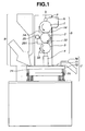
- FIGS. 1 and 2 show a capsule filling machine having a supplying section 5 which includes defective capsule removing mechanisms according to the first aspect and the optional aspect described above.
- the capsule filling machine successively supplies, by means of the supplying section 5, empty capsules each formed from a cap and a body temporarily coupled to each other (such capsules are hereinafter referred to merely as "empty capsules") in an erected state wherein the cap is directed upwardly, transports the empty capsules keeping such the erected state by means of a transporting apparatus of a filling mechanism section 7, separates the empty capsules into caps and bodies during transportation, fills contents substance into the bodies by a contents substance filling apparatus 6, and couples the caps and the bodies again to each other to produce filled capsule products, and then discharges the filled capsule products from the apparatus and recovers them.
- the supplying section 5 includes, as shown in FIG. 1 , a supply drum (transporting drum) 1 for successively supplying empty capsules accommodated in a hopper h in a state where empty capsules in an vertically erected state with the cap directed upwardly and empty capsules in an inverted state with the body directed upwardly are mixed together, a direction controlling drum 2 for controlling the directions of the empty capsules received from the supply drum 1, a feeding drum 3 for receiving the empty capsules all in an inverted state with the body directed upwardly from the direction controlling drum 2 and transporting the received empty capsules downwardly, and a magazine 4 for loading the empty capsules in an erected state received from the feeding drum 3 into capsule pockets provided on the transporting unit of the filling mechanism section 7.
- a supply drum (transporting drum) 1 for successively supplying empty capsules accommodated in a hopper h in a state where empty capsules in an vertically erected state with the cap directed upwardly and empty capsules in an inverted state with the body directed upwardly are mixed together
- FIGS. 5A and 5B two rows of 21 supply pockets 11 capable of accommodating empty capsules in a vertically standing state therein are formed along a circumferential direction on a circumferential face of the supply drum 1.
- empty capsules AB stored in the hopper h are successively accommodated into the supply pockets 11.
- Each of the supply pockets 11 is formed in such a shape that an opening thereof is partly expanded in a direction of rotation so that an empty capsule from the hopper h can be introduced readily into the supply pocket 11, and is communicated with a suction/blowing out hole 112 formed along an axial direction of the supply drum 1 in the proximity of the diametrally inner side of the supply drum 1.
- a suction/blowing out hole 112 is communicated with two supply pockets 11, 11 which are juxtaposed along a widthwise direction of the supply drum 1 and is open to one side face of the supply drum 1.
- each supply pocket 11 has a defective capsule discharging window 131 provided at a lower portion thereof, which communicates with a capsule discharging space portion 13 which is open to the outer side face of the supply drum 1.
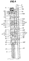
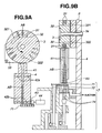
- a first suction and exhaust block 1a is disposed between the supply drum 1 and a column p which supports the supply drum 1 for rotation thereon, and three suction paths 112a, 112b and 13a and one compressed air path 112c are provided on a front face side of the suction and exhaust block 1a (adjacent the supply drum 1) as shown in FIGS. 3 and 4 .
- the suction paths 112a and 112b and the suction/blowing out holes 112 are registered with each other, the insides of the supply pockets 11 are subject to suction, but in another condition where the compressed air path 112c and a suction/blowing out hole 112 are registered with each other, air is blown out into the supply pocket 11.
- a small suction block 1b having a suction path 13b opposing to the suction path 13a is disposed on the opposite side to the first suction and exhaust block 1a with respect to the supply drum 1, and in a condition where the suction path 13b of the small suction block 1b and the suction path 13a of the first suction and exhaust block 1a are registered with the capsule discharging space portions 13, the insides of the supply pockets 11 are subject to suction from the side face sides thereof.
- a pair of right and left guide members 14, 14 for preventing capsules from slipping out are provided along a circumferential face of the supply drum 1 such that they extend vertically from middle portions thereof toward the lower side of the supply drum 1.
- a capsule discharging gap is provided between the two guide members 14, 14 at a position just below the supply drum 1.
- the direction controlling drum 2 is formed with a diameter smaller than the supply drum 1 and is disposed below the supply drum 1 such that a circumferential face thereof is close to the supply drum 1.
- the direction controlling drum 2 rotates in the direction (in the clockwise direction in FIGS. 1 and 3 ) opposite to that of the supply drum 1 at an equal circumferential speed to that of the supply drum 1.
- three sets of direction controlling sections each including six, in total, direction controlling pockets 21 arranged in three rows by two columns are provided with an equal space given from each other in a circumferential direction on the circumferential face of the direction controlling drum 2.
- each of the direction controlling pockets 21 is composed of an upper portion 211 having a substantially elongated elliptical shape capable of accommodating an empty capsule AB, which includes a cap A and a body B temporarily coupled to each other, in a horizontally lying state along a widthwise direction of the direction controlling drum 2, and a bottom portion 212 communicated with an end portion of the upper portion 211 and having a diameter set such that the cap portion A of an empty capsule AB cannot enter the bottom portion 212 but only the body portion B can enter the bottom portion 212.
- each of the direction controlling pockets 21 is communicated with a suction/blowing out hole 23 formed in the proximity of a diametrally inner side of the direction controlling drum 2, and one suction/blowing out hole 23 is communicated with two direction controlling pockets 21, 21 juxtaposed along a widthwise direction of the direction controlling drum 2 and is open to one side face of the direction controlling drum 2. Further, as shown in FIG. 8A , the bottom portion 212 of each of the direction controlling pockets 21 is communicated with a suction/blowing out hole 23 formed in the proximity of a diametrally inner side of the direction controlling drum 2, and one suction/blowing out hole 23 is communicated with two direction controlling pockets 21, 21 juxtaposed along a widthwise direction of the direction controlling drum 2 and is open to one side face of the direction controlling drum 2. Further, as shown in FIG.
- a second suction and exhaust block 2a is disposed between the column p on which the direction controlling drum 2 is supported and the direction controlling drum 2 in a similar manner as in the case of the supply drum 1 described hereinabove, and a suction path 231 and a compressed air path 232 are provided on a front face side of the second suction and exhaust block 2a (adjacent the direction controlling drum 2) as shown in FIGS. 3 and 4 .
- the suction path 231 and the suction/blowing out hole 23 are registered with each other, the inside of the direction controlling pocket 21 is subject to suction, but in another condition where the compressed air path 232 and the suction/blowing out hole 23 are registered with each other, air is blown out into the direction controlling pocket 21.
- the upper portion 211 of each of the direction controlling pockets 21 is formed as a cap holding portion 211a with opposed end side thereof has a reduced width.
- the width W of the cap holding portion 211a is set to a little greater than the diameter of the body B of the empty capsule AB, but a little smaller than the diameter of the cap A, so that an empty capsule AB accommodated in the upper portion 211 of the direction controlling pocket 21 with the cap A thereof directed to the cap holding portion 211a side is held at the cap A portion by the cap holding portion 211a and cannot be discharged readily.
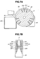
- two sets of scraper insertion grooves 24 each including two scraper insertion grooves 24 are formed along a circumferential direction of the drum 2 on the outer circumferential face of the direction controlling drum 2 as shown in FIGS. 7A, 7B and 8A, 8B .
- the two sets of scraper insertion grooves 24, 24 extend across the upper portions 211 of the direction controlling pockets 21.
- a direction controlling guide member 22 for preventing the empty capsule AB from slipping out and controlling direction of empty capsules AB accommodated in the direction controlling pockets 21 is provided along the one circumferential face of the direction controlling drum 2 over an approximately 1/4 circumferential portion thereof from one side portion (right side portion in the figures) to the lower side.
- the direction controlling guide member 22 has two V-shaped grooves 221, 221 formed thereon corresponding to the direction controlling pockets 21 as shown in FIG.
- a mountain-like shaped portion formed between the V-shaped grooves 221, 221 serves as a direction controlling protrusion 222 for laying down an empty capsule AB accommodated in the direction controlling pocket 21 in an inverted state into a horizontally lying state.
- FIGS. 1 , 3 , 7A and 7B four spike-shaped scrapers 25 are disposed at the other side portion of the circumferential face of the direction controlling drum 2 (on the side opposite to the direction controlling guide member 22), and extremities of them are fitted in the scraper insertion grooves 24. Further, a recovery can 251 for recovering empty capsules AB discharged from the upper portions 211 of the direction controlling pockets 21 by the scrapers 25 is disposed below the scrapers 25.
- the feeding drum 3 is formed with a diameter smaller than that of the supply drum 1 similarly to the direction controlling drum 2 described hereinabove and is disposed below the direction controlling drum 2 in a condition where a circumferential face thereof is close to the direction controlling drum 2.
- the feeding drum 3 rotates in the direction (counterclockwise direction FIG. 1 ) opposite to that of the direction controlling drum 2 at a circumferential speed equal to that of the direction controlling drum 2.
- FIGS. 3 , 9A and 9B three sets of feeding sections each including six, in total, feeding pockets 131 arranged in three rows by two columns are provided with an equal space given from each other in a circumferential direction on the circumferential face of the feeding drum 3 similarly as in the direction controlling drum 2.
- each of the feeding pockets 31 is formed in such a shape that an opening thereof is partly expanded in a widthwise direction of the feeding drum 3 so that an empty capsule AB can be introduced into the feeding pocket 31 readily, and is communicated with a suction/blowing out hole 32 formed in the proximity of the diametrally inner side of the feeding drum 3.
- one suction/blowing out hole 32 is communicated with two feeding pockets 31, 31 juxtaposed with each other along a widthwise direction of the feeding drum 3 and is open to one side face of the feeding drum 3.
- a third suction and exhaust block 3a is disposed between the feeding drum 3 and the column p on which the feeding drum 3 is supported in a similar manner as in the case of the supply drum 1 and the direction controlling drum 2.
- a suction path 321 and a compressed air path 322 are provided on the front face side (adjacent the feeding drum 3) of the third suction and exhaust block 3a as shown in FIGS. 3 , 4 , 9A and 9B .
- a guide member 33 for preventing a capsule from slipping out is provided along the circumferential face of the feeding drum 3 extending from one side portion (left side portion in the figures) to the lower side of the circumferential face of the feeding drum 3.
- the magazine 4 which can accommodate a predetermined number of empty capsules AB is disposed below the feeding drum 3. As shown in FIGS. 3 , 9A and 9B , the magazine 4 has two capsule supply paths 41 each having a hollow of a diameter a little greater than the outer diameter of the empty capsules AB. Empty capsules AB charged from the feeding drum 3 are accommodated once into the capsule supply paths 41 and aligned along a vertical direction in a vertically standing state in the capsule supply paths 41, and the empty capsules AB are successively supplied from the lower ends of the capsule supply paths 41 to the filling mechanism section 7.
- the magazine 4 is disposed at a position at which, when a feeding pocket 31 passes by the guide member 33 and is opened downwardly as a result of rotation of the feeding drum 3, the top end opening of one of the capsule supply paths 41 is opposed to the opening of the feeding pocket 31.
- the capsule supply path 41 is formed in such a shape that the opening thereof is partly expanded toward the direction of rotation of the feeding drum 3 so that an empty capsule AB can enter the capsule supply path 41 with certainty.
- photoelectric sensors 42a, 42b formed from a pair of light emission and reception elements are disposed at a lower end portion and an upper portion of the magazine 4.
- the insides of the capsule supply paths 41 are normally supervised by the photoelectric sensors 42a, 42b to detect presence or absence of an empty capsule AB and a rough number of such empty capsules AB, and a shutter 43 (refer to FIGS. 9A and 9B ) disposed at a lower end portion of the magazine 4 is opened or closed by an air cylinder 44 (refer to FIG. 9A ) in response to a result of the detection.
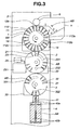
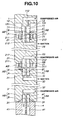
- the supplying section 5 which includes the supply drum 1, direction controlling drum 2, feeding drum 3 and magazine 4 is described with reference to FIGS. 3 , 4 and 10 .
- empty capsules AB accommodated in the hopper h are successively supplied to and accommodated into the supply pockets 11 of the supply drum 1 (refer to FIG. 3 ).
- the supply drum 1 rotates in the counterclockwise direction as in FIG. 3 and the supply pockets 11 pass the supplying location from the hopper h, one of the suction/blowing out holes 112 communicated with the supply pockets 11 is registered with the suction path 112a so that the insides of the supply pockets 11 are sucked.
- empty capsules AB are accommodated from the hopper h into the supply pockets 11 with certainty by making use of an attracting force by suction.
- the empty capsules AB accommodated in the supply pockets 11 exhibit a condition where those in the erected state with the cap A directed upwardly and those in the inverted state with the body B directed upwardly are mixed together.
- the capsules accommodated in the supply pockets 11 of the supply drum 1 are transported to the lower side of the supply drum 1 as the supply drum 1 rotates and are transported to the direction controlling pockets 21 of the direction controlling drum 2.
- one of the suction/blowing out holes 112 which is communicated with supply pockets 11 is registered with the compressed air path 112c (refer to FIGS. 3 and 4 ) and one of the suction/blowing out holes 23 which is communicated with direction controlling pockets 21 is registered with the suction path 231 (refer to FIGS. 3 and 4 ). Consequently, as shown in FIG. 10 , air is blown out from the supply pockets 11 to force out the accommodated empty capsules AB while the direction controlling pockets 21 are brought into a sucking condition so that the empty capsules AB are received with certainty.
- empty capsules AB supplied from the hopper h to the supply drum 1 are not transferred from the supply drum 1 to the direction controlling drum 2 during a first round of rotation of the supply drum 1, but after they pass by the supplying location from the hopper h, they are transferred to the direction controlling drum 2 during a second round of rotation. Accordingly, even if an empty capsule AB is not successfully accommodated into one of the supply pockets 11 upon supplying of empty capsules AB from the hopper h, leaving the supply pocket 11 empty, when the supply pocket 11 passes by the supplying location from the hopper h for the second round, an empty capsule AB is accommodated into the empty pocket. Consequently, empty capsules AB are supplied to the direction controlling drum 2 with certainty while an empty direction controlling pocket 21 does not appear on the direction controlling drum 2.
- each empty capsule AB is composed of the cap A and the body B which are temporarily coupled to each other such that they can be separated from each other readily, the cap A and the body B are liable to be separated, and there is a case that caps A and bodies B of empty capsules AB separate from each other are sometimes present in the hopper h. If such a cap A or body B is accommodated solely into a supply pocket 11 of the supply drum 1, then the cap A or body B accommodated solely in the supply pocket 11 is removed at a location at which a brush roller b is disposed (refer to FIGS. 3 and 4 ) immediately after the capsule supplying location from the hopper h.
- the capsule discharging space portion 13 (refer to FIG. 4 ) communicated with the supply pockets 11 is registered with the suction path 13a of the first suction and exhaust block 1a or the suction path 13b of the small suction block 1b and the insides of the supply pockets 11 are subject to suction.
- a body B is accommodated solely in one of the supply pockets 11, for example, as shown in FIG.
- the body B is sucked by an attracting force generated by the suction from the suction path 13a (or 13b) through a defective capsule discharging window 131 provided at the lower portion of the supply pocket 11 into the capsule discharging space portion 13 in a rolling condition and discharged and removed from the supply pocket 11.
- an empty capsule AB composed of a cap A and a body B coupled to each other has a greater length than the sole cap A or the sole body B, it will be caught in the supply pocket 11 and cannot be rolled out from the supply pocket 11 into the defective capsule discharging window 131 and consequently will not be sucked out of the supply pocket 11 to the capsule discharging space portion 13.
- the defective capsule discharging window 131 described above has a length set smaller than that of a capsule AB, so that a normal empty capsule AB composed of the cap A and the body B temporarily coupled to each other cannot be discharged through the defective capsule discharging window 131
- the length of the defective capsule discharging window 131 is suitably adjusted to a length with which, taking the width (diameter) of the supply pockets 11 and the diameter and the length of the empty capsule AB into consideration, the cap A and the body B can pass through the defective capsule discharging window under tilting relative to the pocket axis, but an empty capsule composed of the cap A and the body B temporarily coupled to each other cannot tilt into the defective capsule discharging window.
- each empty capsule AB which has entered with the body B side directed forwardly and been accommodated into a direction controlling pocket 21 of the direction controlling drum 2 is fully accommodated in the direction controlling pocket 21 in an erected state with the cap A thereof directed upwardly (adjacent the circumferential face of the drum) and with the body B thereof entered to the bottom portion 212 of the direction controlling pocket 21.
- each empty capsule AB' which has entered with the cap A side directed forwardly and been accommodated into a direction controlling pocket 21 cannot enter the bottom portion 212 because the diameter of the cap A is greater than the diameter of the bottom portion 212, and is held in the direction controlling pocket 21 in a state wherein the body B portion projects from the circumferential face of direction controlling the drum.
- the body B portion projecting from the circumferential face of the drum enters a V-shaped groove 221 (refer to FIG. 7B ) of the direction controlling guide member 22 and is in contact with a side edge portion of the direction controlling protrusion 222 (refer to FIG. 7B ).
- the empty capsule AB' is pressed outwardly in a widthwise direction of the drum 2 so that it is fallen down into the upper portion 211 of the direction controlling pocket 21 around a fulcrum provided by the end of the cap portion A.
- the empty capsule AB' is accommodated into and held in the upper portion 211 of the direction controlling pocket 21 in a horizontally lying state along a widthwise direction of the drum 2.
- the empty capsule AB' accommodated in a horizontally lying state in the upper portion 211 of the direction controlling pocket 21 has the cap A portion thereof positioned on the bottom portion 212 of the direction controlling pocket 21 and has the body B side directed to the outer side.
- the empty capsules AB and AB' accommodated in the direction controlling pockets 21 of the direction controlling drum 2 in this manner are transferred to the feeding pockets 31 of the feeding drum 3 as shown in FIG. 10 .
- the suction/blowing out hole 23 communicated with the direction controlling pockets 21 is registered with the compressed air path 232 (refer to FIGS. 3 and 4 ) and the suction/blowing out hole 32 communicated with the feeding pockets 31 is registered with the suction path 321 (refer to FIGS. 3 and 4 ). Consequently, as shown in FIG.
- the empty capsules AB having been accommodated in the direction controlling pockets 21 in an erected state with the body B portions thereof entered the bottom portions 212 of the direction controlling pockets 21 are entered the feeding pockets 31 with the cap A sides thereof directed forwardly and are accommodated in an inverted state with the body B sides directed upwardly (adjacent the drum circumferential face side).
- an empty capsule AB' accommodated in the horizontally lying state at the upper portion 211 of a direction controlling pocket 21 is forced out to a feeding pocket 31 with the cap A directed forwardly by air blown out from the bottom portion 212 of the direction controlling pocket 21 and is sucked into the feeding pocket 31 with the cap A directed forwardly.
- the empty capsule AB' is entered the feeding pocket 31 with the cap A directed forwardly until it is accommodated in an inverted state with the body B directed upwardly (adjacent the drum circumferential face). Accordingly, the empty capsules AB and AB' transferred to the feeding drum 3 are all accommodated in an inverted state with the bodies side B thereof directed upwardly in the feeding pockets 31.
- each of the empty capsules AB is transferred from a supply pocket 11 of the supply drum 1 into a direction controlling pocket 21 of the direction controlling drum 2, even if it is in an erected state which allows it to enter the direction controlling pocket 21 with the body B directed forwardly, it sometimes occurs by some reason that the body B portion thereof does not enter the bottom portion 212 of the direction controlling pocket 21, but it is accommodated into the upper portion 211 of the direction controlling pocket 21 in a reversely horizontally lying state wherein the cap A side is directed to the outside or the cap A portion of the empty capsule AB projects from the circumferential face of the drum in an erected state with the cap A directed upwardly and the empty capsule AB is laid down horizontally by the direction controlling guide member 22 into a reversely horizontally lying state wherein the cap A is directed to the outside.
- the reversely horizontally lying capsule is accommodated in the upper portion 211 of a direction controlling pocket 21 in a condition where the cap A side thereof is directed to the outside of the direction controlling drum 2, since the upper portion 211 of the direction controlling pocket 21 is formed as a cap holding portion 211a in which the width w of an outer side portion of which is smaller than the diameter of the cap A as shown in FIG. 8-B , the reversely horizontally lying capsule is pressed by the direction controlling guide member 22 (refer to FIG. 3 ) so that it is put into a condition where it is confined to the cap holding portion 211a of the upper portion 211 of the direction controlling pocket 21 and cannot be pulled out readily from the direction controlling pocket 21.
- the reversely horizontally lying capsule does not move to a feeding pocket 31 of the feeding drum 3, but passes by the hand-over point and is further transported while it is held in the upper portion 211 of the direction controlling pocket 21. Then, the reversely horizontally lying capsule is scraped out from the upper portion 211 of the direction controlling pocket 21 by the scraper 25 (refer to FIG. 7A ) inserted in one of the scraper insertion grooves 24 (refer to FIGS. 7A, 7B , 8A and 8B ) which extends across the upper portion 211 of the direction controlling pocket 21 and is recovered into the recovery can 251.
- the empty capsules AB and AB' in an erected state transferred from the direction controlling drum 2 to the feeding drum 3 in such a manner as described above move to the lower side as the feeding drum 3 rotates, and are charged into the capsule supply paths 41, 41 of the magazine 4 disposed under the feeding drum 3 with the bodies B thereof directed forwardly as shown in FIG. 10 . Consequently, a predetermined number of empty capsules AB are reserved once in a condition where all of them are put into such a status that they are registered in a vertical direction in an upright state and then are successively supplied to the filling mechanism section 7 from the lower end openings of the capsule supply paths 41, 41.
- each of the capsule supply paths 41 is closed by the shutter 43 when the filling machine is activated, and at a point of time when a predetermined number of empty capsules AB are reserved in the capsule supply paths 41 and detected by the photoelectric sensor 42a on the upper side and it is confirmed that the predetermined number of empty capsules AB are reserved therein, the air cylinders 44 is operated to open the shutters 43 to start a supplying operation of the empty capsules AB into the filling mechanism section 7.
- the feeding pockets 31 provided on the feeding drum 3 are disposed such that three sets of feeding pocket groups each including six, in total, feeding pockets 31 arranged in three rows by two columns as described above are spaced from each other given an equal distance, although the feeding drum 3 continuously rotates at a fixed speed, charging of empty capsules AB into the capsule supply paths 41 of the magazine 4 from the feeding drum 3 is performed such that an operation of charging, after six, in total, empty capsules arranged in three rows by two columns are successively charged, next six empty capsules are charged successively after lapse of a predetermined time and is repeated. Thus, successive charging is repeated intermittently.
- supply of empty capsules from the lower end openings of the capsule supply paths 41 of the magazine 4 into the charging mechanism section 7 is performed successively. Consequently, supply of empty capsules AB to the charging mechanism section 7 is performed while increasing and decreasing of the number of empty capsules AB reserved in the capsule supply paths 41 of the magazine 4 are repeated.
- the filling mechanism section 7 having received the empty capsules AB from the magazine 4 accommodates the empty capsules AB in an erected state into capsule pockets, each composed of a cap pocket of a cap segment 71 and a body pocket of a body disk 72, separates the empty capsules accommodated in the capsule pockets into caps A and bodies B, holds and transports the caps A and the bodies B in the cap pockets of the cap segment 71 and the body pockets of the body disk 72, respectively, separates the cap segment 71 from the body disk 72 and performs a separation defective inspection by means of a separation defective detector 77.
- the filling mechanism section 7 fills contents substance into the bodies B held in the body disk 72 by means of the contents substance filling apparatus 6, contacts the cap segment 71 with the body disk 72 again, pushes up the bodies B by means of plunger pins 74 to the caps A held by a holding plate 73 to temporarily couple the caps A and the bodies B to each other, further presses the caps A by means of a coupling roller 75 to fully couple the caps A and the bodies B to each other, further pushes up resulting filled capsule products C by means of the plunger pins 74 to discharge the filled capsule products C from the body disk 72 and the cap segment 71, and discharges the filled capsule products C to the outside of the apparatus through a discharging chute 76 to recover them.
- cap pockets of the cap segment 71 and the body pockets of the body disk 72 are cleaned by a cleaner 78 (refer to FIG. 2 ) and the filling mechanism section 7 receives empty capsules AB from the supplying section 5 again so that similar operations are repeated.
- the capsule filling machine of the present embodiment successively supplies empty capsules AB each composed of a cap and a body temporarily coupled to each other while controlling the posture of the empty capsules AB to an erected state with the cap A directed upward by means of the supplying section 5, transports the empty capsules AB by means of the transporting unit of the filling mechanism section 7 with the empty capsules AB kept in the erected state, the empty capsules AB are separated into caps and bodies during transportation, fills contents substance into the bodies B by means of the contents substance filling apparatus 6, and couples the caps A and the bodies B to each other again to produce filled capsule products C, and then discharges and recovers the filled capsule products C from the apparatus.
- the removing mechanism for removing a coupling defective capsule provided for the supply drum 1 of the supplying section 5
- a reverse defective capsule is automatically disabled from being transferred to the feeding drum 3 without the necessity to perform any operation and without the necessity for a complicated mechanism for detecting whether a capsule accommodated in a direction controlling pocket 21 is a capsule in a normal horizontally lying state directed in a predetermined direction or a reverse defective capsule in a horizontally lying state directed in the opposite direction, or for selectively discharging and removing a detected reverse defective capsule, and in this state, the reverse defective capsule passes by the hand-over point to the feeding drum 3 and is then compulsorily removed from the direction controlling pocket 21 automatically by the scraper 25 at the predetermined location on the downstream side of the hand-over point to the feeding drum 3 in the transportation direction to which a normal capsule is not transported at all. Consequently, a reverse defective capsule can be discharged and removed simply and with certainty without the necessity for a complicated structure, cumbersome control and so forth.
- the defective capsule removing mechanism of the present invention is not limited to the embodiment described above but can be suitably modified.
- the removing mechanism of the present invention is employed in a supplying section of a capsule filling machine which supplies empty capsules while controlling the posture of them to an erected state
- a supplying section which is used in a capsule sealing machine or a capsule appearance inspection apparatus for supplying capsules while controlling the posture of them to a horizontally lying state directed in a fixed direction.
- the directions of the upper portions 211 of the direction controlling pocket 21 of the direction controlling drum 2 are all set to the same direction, and a second direction controlling drum 30 which is similar to the feeding drum 3 except that it does not have the removing mechanism is used in place of the feeding drum 3.
- empty capsules AB' supplied in an inverted state from the supply drum 1 are put into a horizontally lying state by the first direction controlling drum 2 while empty drums AB supplied in an erected state from the supply drum 1 are put into a horizontally lying state by the second direction controlling drum 30 so that all capsules are supplied after the postures thereof are converted into a horizontally lying state wherein their directions are controlled to the fixed direction.
- the other construction is similar to that of the supplying unit 5 of the embodiment described hereinabove.
- the defective capsule removing mechanism of the present invention can be used as a mechanism for removing a a reverse defective capsule, optionally coupling defective capsule, from a capsule pocket of a transporting unit which merely transports capsules without performing directional control.
- the shapes, the numbers, the number of columns, the arrangement method and so forth of the pockets provided on the drums 1, 2 and 3 can be modified suitably, and also the other construction may be modified suitably.
- a reverse defective capsule can be discharged and removed automatically and with certainty by a comparatively simple mechanism.
Landscapes
- Engineering & Computer Science (AREA)
- Mechanical Engineering (AREA)
- Health & Medical Sciences (AREA)
- General Physics & Mathematics (AREA)
- Physics & Mathematics (AREA)
- Life Sciences & Earth Sciences (AREA)
- Chemical & Material Sciences (AREA)
- Public Health (AREA)
- Veterinary Medicine (AREA)
- Animal Behavior & Ethology (AREA)
- Pharmacology & Pharmacy (AREA)
- Medicinal Chemistry (AREA)
- General Health & Medical Sciences (AREA)
- Medical Preparation Storing Or Oral Administration Devices (AREA)
- Feeding Of Articles To Conveyors (AREA)
- Basic Packing Technique (AREA)
- Supplying Of Containers To The Packaging Station (AREA)
- Specific Conveyance Elements (AREA)
- Attitude Control For Articles On Conveyors (AREA)
Claims (10)
- Kapseltransportanordnung zum Transport von Kapseln, die eine an einem Körper (B) angebrachte Kappe (A) aufweisen, wobei die Kappe einen größeren Durchmesser aufweist als der Körper;
wobei die Transportanordnung einen Transportkörper (2) mit einer Kapseltasche (21) umfasst, die an einer nach außen gerichteten Fläche offen ist und geformt ist, um die Kapsel (AB) entlang der Außenfläche liegend aufzunehmen, um sie entlang eines Transportwegs zu transportieren;
dadurch gekennzeichnet, dass
ein Ende der Kapseltasche (21) ein Kappengreifabschnitt (211a) ist, der eine reduzierte Weite aufweist, die weiter als der Durchmesser des Kapselkörpers ist, aber geringer als der Durchmesser der Kapselkappe ist, wodurch eine fehlerhaft verkehrte Kapsel (AB), d.h. eine die so in der Tasche liegt, dass ihre Kappe (A) in Richtung dieses Endes weist, durch den Kappengreifabschnitt in der Tasche (21) gehalten wird, und dadurch, dass
die Außenfläche des Transportkörpers eine Heberille (24) aufweist, die quer durch die Tasche (21) hindurch verläuft, vorzugsweise zumindest an deren Kappengreifabschnitt (211a), und die Anordnung ein Hebeelement (25) umfasst, das in der Rille (24) an einer Stelle zur Entfernung fehlerhaft verkehrt vorliegender Kapseln betätigbar ist, um etwaige fehlerhaft verkehrt vorliegende Kapseln, die darin enthalten sind, zu entfernen. - Kapseltransportanordnung nach Anspruch 1 mit einer Stelle zur Weiterleitung, an der eine richtig in der Tasche (21) aufgenommene Kapsel aus der Tasche (21) entfernt und zu einem weiteren Bearbeitungsschritt weitergeleitet wird, während festgehaltene, fehlerhaft verkehrt vorliegende Kapseln diese Weiterleitungsstelle passieren, ohne dort entfernt zu werden, und anschließend an der Stelle zur Entfernung fehlerhaft verkehrt vorliegender Kapseln entfernt werden.
- Kapseltransportanordnung nach Anspruch 1 oder 2, worin das Hebeelement ein schräges Abstreiferelement ist, das in die Heberille (24) vorsteht.
- Kapseltransportanordnung nach einem der Ansprüche 1 bis 3, worin die Kapseltasche (21) einen oberen Abschnitt (211) benachbart in Bezug auf die Außenfläche, die die Aufnahme für eine Kapsel (AB) bereitstellt, die entlang der Außenfläche vorliegt, und einen unteren Abschnitt (212) aufweist, der sich in den Transportkörper (2) von einem Ende des oberen Abschnitts (211) hinunter erstreckt und so dimensioniert ist, um nur das Körperende einer Kapsel (AB) zum Transport in aufrechtem Zustand aufzunehmen.
- Kapseltransportanordnung nach Anspruch 4 mit einem Führungsnockenelement (222), das über den Transportweg, der in Bezug auf die Außenfläche des Transportkörpers (21) benachbart vorliegt, geneigt ist, um etwaige Kapseln (AB), die aufrecht und mit dem Körper nach außen vorstehen, in den unteren Abschnitt (211) der Tasche hinunter abzulenken, damit diese entlang der Außenfläche vorliegen.
- Kapseltransportanordnung nach einem der Ansprüche 1 bis 5, worin der Transportkörper (2) eine drehbare Trommel ist.
- Kapseltransportanordnung nach einem der Ansprüche 1 bis 6 zum Transport von Kapseln mit vorbestimmter Länge, wobei die Anordnung einen weiteren Transportkörper (1) mit einer Kapseltasche (11) umfasst, die geformt ist, um eine Kapsel (AB) für den Transport aufzunehmen, und dadurch gekennzeichnet, dass ein Ausgabefenster (131) in einer Seitenwand der Kapseltasche (11) bereitgestellt ist, wobei das Ausgabefenster (131) kürzer ist als die vorbestimmte Länge der Kapseln (AB), in der Nähe eines Endes der Kapseltasche (11) vorliegt und eine Saugöffnung (13) aufweist, über die eine Saugwirkung ausgeübt werden kann, wodurch etwaige Kapselkörper (B) oder Kapselkappen (A), die einzeln in der Tasche vorliegen, selektiv abgezogen werden können, seitlich aus der Tasche (11) durch das Ausgabefenster (131), vorzugsweise unter Neigung, da diese kürzer sind als die vorbestimmte Länge einer vollständigen Kapsel (AB).
- Kapseltransportanordnung nach Anspruch 7, worin die Kapseltasche (11) eine Öffnung aufweist, die durch eine obere oder äußere Oberfläche des weiteren Transportkörpers (1), wie z.B. einer Transporttrommel, verläuft und geformt ist, um die Kapsel so aufzunehmen, dass sich ihre Länge in den Transportkörper (1) nach unten erstreckt, wobei das Ausgabefenster (131) in der Nähe des unteren Endes der Tasche (11) vorliegt.
- Verfahren zur Entfernung fehlerhafter Kapseln, um - wenn eine Kapsel in horizontaler Liegeposition in einer Kapseltasche (21), die an einer Außenumfangsfläche einer Transporttrommel (2) bereitgestellt und zur Aufnahme einer Kapsel in einer horizontalen Liegeposition in der Lage ist, aufgenommen und gehalten wird, wobei ihre Kappenseite in eine bestimmte Richtung ausgerichtet ist, und durch Rotation der Trommel transportiert wird, so dass die Kapsel aus der Kapseltasche (21) in einem vorbestimmten Rotationswinkel ausgegeben wird und in eine andere Transporteinheit (3) oder dergleichen weitergeleitet wird - eine fehlerhaft verkehrte Kapsel zu entfernen, die in der Kapseltasche in umgekehrter Liegeposition aufgenommen ist, wobei die Kappenseite in die entgegengesetzte Richtung ausgerichtet ist, um dadurch zu verhindern, dass eine fehlerhaft verkehrte Kapsel, die in die entgegengesetzte Richtung ausgerichtet ist, unter eine Gruppe von Kapseln gemischt wird, die an die andere Transporteinheit oder dergleichen weitergeleitet werden, dadurch gekennzeichnet, dass:wenn eine Kapsel in verkehrter horizontaler Liegeposition mit der Kappe (A) in die entgegengesetzte Richtung in der Kapseltasche aufgenommen ist, wobei eine Endseite der Kapseltasche (21), an der eine Körperseite der Kapsel aufgenommen werden soll, als Kappengreifabschnitt (211 a) ausgebildet ist, der weiter als der Durchmesser des Körpers (B) der Kapsel, aber schmäler als der Durchmesser der Kappe (A) der Kapsel ist, wobei sich eine Abstreifereinführrille (24) quer durch die Kapseltasche erstreckt, die an der Außenumfangsfläche der Transporttrommel (2) entlang einer Umfangsrichtung der Trommel ausgebildet ist, und wobei ein Abstreifer (25), der einen Endabschnitt aufweist, der in die Abstreifereinführrille eingeführt ist, an der nachgeordnet gelegenen Seite in Bezug auf einen Übergabepunkt an die andere Transporteinheit (3) oder dergleichen in Rotationsrichtung der Trommel angeordnet ist, die Kapsel in einen Zustand gebracht wird, in der der Kappenabschnitt der Kapsel in den Kappengreifabschnitt (211 a) der Kapseltasche (21) eingebracht wird und nicht einfach herausgezogen werden kann, so dass die Kapsel an dem Übergabepunkt zu der weiteren Transporteinheit (3) oder dergleichen nicht aus der Kapseltasche ausgegeben wird, sondern weiter an die nachgeordnet gelegene Seite in Rotationsrichtung der Trommel (2) transportiert wird, wonach sie durch den Abstreifer (25) aus der Kapseltasche abgestreift wird.
- Verfahren zur Entfernung fehlerhafter Kapseln nach Anspruch 9, wobei die Kapseltasche (21) eine Richtungssteuerungstasche ist, die einen oberen Abschnitt (211) zur Aufnahme einer Kapsel in horizontaler Liegeposition und einen unteren Abschnitt (212) umfasst, der mit einem Endabschnitt des oberen Abschnitts kommuniziert und nur das Eintreten des Körpers (B) der Kapsel in den unteren Abschnitt (212) zulässt, wobei der Körperabschnitt einer Kapsel, die in einer aufrechten stehenden Position mit der Körperseite nach vorne ausgerichtet in die Richtungssteuerungstasche (21) eingebracht wurde, die an der Außenumfangsfläche der Richtungssteuerungstrommel (2) ausgebildet ist, in den unteren Abschnitt eintritt und in einer aufrechten stehenden Position in der Richtungssteuerungstasche gehalten wird und durch die Rotation der Trommel weitertransportiert wird, während eine andere Kapsel, die in einer aufrechten stehenden Position mit der Kapselseite nach vorne ausgerichtet in die Richtungssteuerungstasche eingebracht wird, nicht in den unteren Abschnitt eintreten kann, sondern in einer aufrechten stehenden Position so in dem oberen Abschnitt gehalten wird, dass die Körperseite von der Außenumfangsfläche der Trommel (2) vorsteht, so dass bei Transport der Kapsel durch die Rotation der Trommel die von der Außenumfangsfläche der Trommel vorstehende Körperseite durch ein Richtungssteuerungsführungselement (22), das entlang der Außenumfangsfläche der Trommel angeordnet ist, so gedrückt wird, dass die Kapsel in dem oberen Abschnitt (211) der Kapseltasche in horizontaler Liegeposition aufgenommen wird, wobei die Kappe (A) in die bestimmte Richtung ausgerichtet ist, wodurch es zu einer Stellungsänderung kommt, wonach die Kapsel weitertransportiert wird, und dass, wenn eine Kapsel aus der Richtungssteuerungstasche (21) in einem vorbestimmten Rotationswinkel
ausgegeben und an die andere Transporteinheit (3) oder dergleichen weitergeleitet werden soll, die in dem oberen Abschnitt (211) der Richtungssteuerungstasche in verkehrter horizontaler Liegeposition aufgenommene Kapsel, wobei die Kappenseite in die entgegengesetzte Richtung ausgerichtet ist, nicht an die andere Transporteinheit oder dergleichen weitergeleitet wird, sondern an die nachgeordnet gelegene Seite in Rotationsrichtung der Trommel (2) weitertransportiert wird, wonach die Kapsel von dem oberen Abschnitt (211) der Richtungssteuerungstasche (21) ausgegeben und rückgeführt wird.
Priority Applications (4)
| Application Number | Priority Date | Filing Date | Title |
|---|---|---|---|
| JP11026707A JP2000226016A (ja) | 1999-02-03 | 1999-02-03 | 不良カプセルの除去機構 |
| US09/549,560 US6434911B1 (en) | 1999-02-03 | 2000-04-14 | Defective capsule removing mechanism |
| EP00303852A EP1153593B1 (de) | 1999-02-03 | 2000-05-08 | Vorrichtung zum entfernen von fehlerhaften Kapseln |
| ES00303852T ES2385345T3 (es) | 2000-05-08 | 2000-05-08 | Mecanismo para extraer cápsulas defectuosas |
Applications Claiming Priority (3)
| Application Number | Priority Date | Filing Date | Title |
|---|---|---|---|
| JP11026707A JP2000226016A (ja) | 1999-02-03 | 1999-02-03 | 不良カプセルの除去機構 |
| US09/549,560 US6434911B1 (en) | 1999-02-03 | 2000-04-14 | Defective capsule removing mechanism |
| EP00303852A EP1153593B1 (de) | 1999-02-03 | 2000-05-08 | Vorrichtung zum entfernen von fehlerhaften Kapseln |
Publications (2)
| Publication Number | Publication Date |
|---|---|
| EP1153593A1 EP1153593A1 (de) | 2001-11-14 |
| EP1153593B1 true EP1153593B1 (de) | 2012-04-04 |
Family
ID=27223524
Family Applications (1)
| Application Number | Title | Priority Date | Filing Date |
|---|---|---|---|
| EP00303852A Expired - Lifetime EP1153593B1 (de) | 1999-02-03 | 2000-05-08 | Vorrichtung zum entfernen von fehlerhaften Kapseln |
Country Status (3)
| Country | Link |
|---|---|
| US (1) | US6434911B1 (de) |
| EP (1) | EP1153593B1 (de) |
| JP (1) | JP2000226016A (de) |
Families Citing this family (29)
| Publication number | Priority date | Publication date | Assignee | Title |
|---|---|---|---|---|
| JP4565486B2 (ja) * | 2001-08-07 | 2010-10-20 | 日本水産株式会社 | トレー供給方法及びトレー供給装置 |
| US20040011806A1 (en) * | 2002-07-17 | 2004-01-22 | Luciano Packaging Technologies, Inc. | Tablet filler device with star wheel |
| ITFI20030012A1 (it) * | 2003-01-15 | 2004-07-16 | Giuseppe Piemontese | Un procedimento di sigillatura di capsule ed un'attrezzatura |
| US20050242304A1 (en) * | 2004-04-29 | 2005-11-03 | Armbuster Lynn E | Diffuse light pharmaceutical inspection system and process |
| JP2006213381A (ja) * | 2005-02-07 | 2006-08-17 | Top:Kk | 連続充填封止装置 |
| DE102005016169A1 (de) * | 2005-04-07 | 2006-10-12 | Grünenthal GmbH | Verfahren und Vorrichtung zum Aussortieren von Kappen |
| US8802183B2 (en) | 2005-04-28 | 2014-08-12 | Proteus Digital Health, Inc. | Communication system with enhanced partial power source and method of manufacturing same |
| DE102006035280A1 (de) * | 2006-07-31 | 2008-02-07 | Robert Bosch Gmbh | Vorrichtung und Verfahren zum Ausstoßen zumindest einer Kapsel |
| DE102008013403A1 (de) * | 2008-03-10 | 2009-09-17 | Robert Bosch Gmbh | Kapselträgeranordnung für Füll- und Verschließmaschinen |
| IT1392277B1 (it) * | 2008-12-18 | 2012-02-24 | Ima Spa | Macchina e metodo per riempire e controllare capsule |
| SG10201502720VA (en) | 2010-04-07 | 2015-05-28 | Proteus Digital Health Inc | Miniature ingestible device |
| KR101244223B1 (ko) * | 2010-11-29 | 2013-03-18 | 주식회사 세종파마텍 | 약품 공급장치 |
| WO2012089302A1 (en) * | 2010-12-30 | 2012-07-05 | Philip Morris Products S.A. | Selection apparatus for objects |
| CN103029963B (zh) * | 2011-10-10 | 2015-07-15 | 东京威尔斯股份有限公司 | 工件输送装置 |
| DE102014209001A1 (de) * | 2014-05-13 | 2015-11-19 | Hekuma Gmbh | Verfahren und Vorrichtung zum Ausrichten von Einzelelementen, insbesondere Filterelementen, beim Transfer zur weiteren Verarbeitung |
| CN104401696B (zh) * | 2014-10-20 | 2017-05-24 | 陈卫国 | 锁具弹子单向排列检测整理装置 |
| WO2017013644A2 (en) * | 2015-07-22 | 2017-01-26 | Pres-By Vision Ltd | Contact lens for vision correction |
| CN105170477A (zh) * | 2015-09-18 | 2015-12-23 | 盛浩洋 | 新型残次胶囊分拣机 |
| US11595595B2 (en) | 2016-09-27 | 2023-02-28 | Rxsafe Llc | Verification system for a pharmacy packaging system |
| US10187593B2 (en) | 2016-09-27 | 2019-01-22 | Rxsafe Llc | Verification system for a pharmacy packaging system |
| CA3041041A1 (en) | 2016-10-26 | 2018-05-03 | Proteus Digital Health, Inc. | Methods for manufacturing capsules with ingestible event markers |
| CN107472613B (zh) * | 2017-01-19 | 2019-04-26 | 张扬 | 一种处理胶囊用吸附头 |
| EP3694466A4 (de) | 2017-10-13 | 2021-07-07 | Rxsafe Llc | Universalzuführmechanismus für automatische verpackungseinrichtung |
| US11305908B2 (en) * | 2019-09-20 | 2022-04-19 | Aylward Enterprises, Llc | Tablet counter and packaging module and associated method |
| CN111470134B (zh) * | 2020-04-21 | 2021-08-20 | 青岛市妇女儿童医院 | 一种表面麻醉药剂用胶囊药物的初步拆分方法 |
| JP7586475B2 (ja) * | 2020-11-24 | 2024-11-19 | 電元社トーア株式会社 | ボルト切出し装置 |
| CN112957339B (zh) * | 2021-02-09 | 2022-11-25 | 桂林华信制药有限公司 | 缬沙坦胶囊的制备工艺 |
| US12134494B2 (en) | 2022-01-03 | 2024-11-05 | Rxsafe, Llc | Verification system for a pharmacy packaging system |
| EP4282395B1 (de) * | 2022-05-23 | 2024-09-25 | Harro Höfliger Verpackungsmaschinen GmbH | Kapselfüllmaschine |
Family Cites Families (10)
| Publication number | Priority date | Publication date | Assignee | Title |
|---|---|---|---|---|
| US3693320A (en) * | 1970-11-09 | 1972-09-26 | Carl C Garland | Novel capsule finishing apparatus |
| US3997058A (en) | 1976-01-29 | 1976-12-14 | Smithkline Corporation | Capsule inspection machine |
| JPS5296195A (en) | 1976-02-04 | 1977-08-12 | Osaka Jidouki Seisakushiyo Kk | Rotary apparatus for reeorientating and charging capsules |
| US4500012A (en) | 1982-06-01 | 1985-02-19 | Ackley E Michael | Capsule handling apparatus |
| CA1259966A (en) * | 1985-02-27 | 1989-09-26 | Taizo Yamamoto | Capsule filling apparatus |
| US4802323A (en) * | 1987-10-20 | 1989-02-07 | Smithkline Beckman Corporation | Automated inspection of capsule seals |
| DE3830013C2 (de) * | 1988-09-03 | 1996-10-17 | Bosch Gmbh Robert | Füll- und Schließmaschine für zweiteilige Kapseln |
| ATE223692T1 (de) * | 1994-06-16 | 2002-09-15 | Warner Lambert Co | Verfahren und vorrichtung zum herstellen von geschlossenen kapseln |
| IT1278210B1 (it) * | 1995-05-19 | 1997-11-17 | Ima Spa | Macchina automatica per il confezionamento di compresse entro capsule di gelatina |
| JP3687710B2 (ja) * | 1997-02-17 | 2005-08-24 | シオノギクオリカプス株式会社 | 固形製剤の外観検査装置 |
-
1999
- 1999-02-03 JP JP11026707A patent/JP2000226016A/ja active Pending
-
2000
- 2000-04-14 US US09/549,560 patent/US6434911B1/en not_active Expired - Lifetime
- 2000-05-08 EP EP00303852A patent/EP1153593B1/de not_active Expired - Lifetime
Also Published As
| Publication number | Publication date |
|---|---|
| EP1153593A1 (de) | 2001-11-14 |
| US6434911B1 (en) | 2002-08-20 |
| JP2000226016A (ja) | 2000-08-15 |
Similar Documents
| Publication | Publication Date | Title |
|---|---|---|
| EP1153593B1 (de) | Vorrichtung zum entfernen von fehlerhaften Kapseln | |
| US6739455B2 (en) | Defective capsule removing mechanism | |
| US6499279B1 (en) | Capsule filling machine | |
| KR100542477B1 (ko) | 고형 제제의 외관검사장치 | |
| EP0077576B1 (de) | Verfahren und Vorrichtung zum Ausrichten von Kapseln | |
| JP3123626B2 (ja) | 固形製剤印刷装置 | |
| US6741731B1 (en) | Side surface inspecting apparatus for tablet, front and back surface inspecting apparatus for tablet, and tablet appearance inspecting apparatus using the same | |
| US4104966A (en) | Capsule orienting and turning apparatus | |
| US4266477A (en) | Material orientation apparatus and method | |
| JPH08500073A (ja) | カプセル封じ装置及び方法 | |
| JP2000226016A5 (de) | ||
| JPS6341311A (ja) | 中空体の選別兼向き修正装置 | |
| EP0919377A1 (de) | Vorrichtung und Verfahren zur beidseitigen Markierung von pillenförmigen Objekten | |
| JP2008008897A (ja) | 錠剤の表裏面外観検査装置、側面外観検査装置及び外観検査装置 | |
| US4413556A (en) | Material orientation apparatus and method | |
| JPH06521B2 (ja) | 容器内ヘのカプセル充填装置 | |
| JPH0735693A (ja) | 固形製剤の外観検査装置 | |
| JP2946086B2 (ja) | 棒状物品の搬送装置における姿勢制御方法及び装置 | |
| JP4853673B2 (ja) | 不良カプセルの除去機構 | |
| US6079546A (en) | Method for carrying containers such as bottles and the like, and plant for its implementation | |
| JP3894239B2 (ja) | カプセル充填機 | |
| ES2385345T3 (es) | Mecanismo para extraer cápsulas defectuosas | |
| JPH06316324A (ja) | 円錐形のチューブを整向するための装置 | |
| WO1997001764A1 (en) | Apparatus for orienting and loading compact medicaments | |
| JP3365545B2 (ja) | カプセルの検査方法と装置 |
Legal Events
| Date | Code | Title | Description |
|---|---|---|---|
| PUAI | Public reference made under article 153(3) epc to a published international application that has entered the european phase |
Free format text: ORIGINAL CODE: 0009012 |
|
| AK | Designated contracting states |
Kind code of ref document: A1 Designated state(s): AT BE CH CY DE DK ES FI FR GB GR IE IT LI LU MC NL PT SE Kind code of ref document: A1 Designated state(s): DE ES FR GB IT |
|
| AX | Request for extension of the european patent |
Free format text: AL;LT;LV;MK;RO;SI |
|
| 17P | Request for examination filed |
Effective date: 20020306 |
|
| AKX | Designation fees paid |
Free format text: DE ES FR GB IT |
|
| 17Q | First examination report despatched |
Effective date: 20071029 |
|
| GRAP | Despatch of communication of intention to grant a patent |
Free format text: ORIGINAL CODE: EPIDOSNIGR1 |
|
| RIC1 | Information provided on ipc code assigned before grant |
Ipc: B65G 47/256 20060101ALI20111003BHEP Ipc: A61J 3/07 20060101AFI20111003BHEP Ipc: B65G 47/244 20060101ALI20111003BHEP |
|
| GRAS | Grant fee paid |
Free format text: ORIGINAL CODE: EPIDOSNIGR3 |
|
| GRAA | (expected) grant |
Free format text: ORIGINAL CODE: 0009210 |
|
| AK | Designated contracting states |
Kind code of ref document: B1 Designated state(s): DE ES FR GB IT |
|
| REG | Reference to a national code |
Ref country code: GB Ref legal event code: FG4D |
|
| REG | Reference to a national code |
Ref country code: DE Ref legal event code: R096 Ref document number: 60047045 Country of ref document: DE Effective date: 20120531 |
|
| REG | Reference to a national code |
Ref country code: ES Ref legal event code: FG2A Ref document number: 2385345 Country of ref document: ES Kind code of ref document: T3 Effective date: 20120723 |
|
| PLBE | No opposition filed within time limit |
Free format text: ORIGINAL CODE: 0009261 |
|
| STAA | Information on the status of an ep patent application or granted ep patent |
Free format text: STATUS: NO OPPOSITION FILED WITHIN TIME LIMIT |
|
| 26N | No opposition filed |
Effective date: 20130107 |
|
| REG | Reference to a national code |
Ref country code: DE Ref legal event code: R097 Ref document number: 60047045 Country of ref document: DE Effective date: 20130107 |
|
| REG | Reference to a national code |
Ref country code: FR Ref legal event code: PLFP Year of fee payment: 17 |
|
| REG | Reference to a national code |
Ref country code: FR Ref legal event code: PLFP Year of fee payment: 18 |
|
| REG | Reference to a national code |
Ref country code: FR Ref legal event code: PLFP Year of fee payment: 19 |
|
| PGFP | Annual fee paid to national office [announced via postgrant information from national office to epo] |
Ref country code: IT Payment date: 20190530 Year of fee payment: 20 Ref country code: ES Payment date: 20190603 Year of fee payment: 20 Ref country code: DE Payment date: 20190430 Year of fee payment: 20 |
|
| PGFP | Annual fee paid to national office [announced via postgrant information from national office to epo] |
Ref country code: FR Payment date: 20190430 Year of fee payment: 20 |
|
| PGFP | Annual fee paid to national office [announced via postgrant information from national office to epo] |
Ref country code: GB Payment date: 20190508 Year of fee payment: 20 |
|
| REG | Reference to a national code |
Ref country code: DE Ref legal event code: R071 Ref document number: 60047045 Country of ref document: DE |
|
| REG | Reference to a national code |
Ref country code: GB Ref legal event code: PE20 Expiry date: 20200507 |
|
| REG | Reference to a national code |
Ref country code: ES Ref legal event code: FD2A Effective date: 20200826 |
|
| PG25 | Lapsed in a contracting state [announced via postgrant information from national office to epo] |
Ref country code: GB Free format text: LAPSE BECAUSE OF EXPIRATION OF PROTECTION Effective date: 20200507 |
|
| PG25 | Lapsed in a contracting state [announced via postgrant information from national office to epo] |
Ref country code: ES Free format text: LAPSE BECAUSE OF EXPIRATION OF PROTECTION Effective date: 20200509 |