EP1152410A2 - Appareil de commande de servo pour tourne-disque optique - Google Patents
Appareil de commande de servo pour tourne-disque optique Download PDFInfo
- Publication number
- EP1152410A2 EP1152410A2 EP01109777A EP01109777A EP1152410A2 EP 1152410 A2 EP1152410 A2 EP 1152410A2 EP 01109777 A EP01109777 A EP 01109777A EP 01109777 A EP01109777 A EP 01109777A EP 1152410 A2 EP1152410 A2 EP 1152410A2
- Authority
- EP
- European Patent Office
- Prior art keywords
- signal
- error
- dropout
- rotation
- servo control
- Prior art date
- Legal status (The legal status is an assumption and is not a legal conclusion. Google has not performed a legal analysis and makes no representation as to the accuracy of the status listed.)
- Granted
Links
- 230000003287 optical effect Effects 0.000 title claims abstract description 39
- 230000008859 change Effects 0.000 claims description 52
- 230000010354 integration Effects 0.000 claims description 36
- 238000001514 detection method Methods 0.000 claims description 19
- 230000004044 response Effects 0.000 claims description 15
- 230000007423 decrease Effects 0.000 claims description 6
- 230000003247 decreasing effect Effects 0.000 claims description 5
- 238000000034 method Methods 0.000 description 22
- 230000004069 differentiation Effects 0.000 description 20
- 230000007547 defect Effects 0.000 description 18
- 230000015654 memory Effects 0.000 description 16
- 238000010586 diagram Methods 0.000 description 13
- 238000012545 processing Methods 0.000 description 13
- 230000001052 transient effect Effects 0.000 description 7
- 230000004048 modification Effects 0.000 description 5
- 238000012986 modification Methods 0.000 description 5
- 230000008569 process Effects 0.000 description 3
- 230000004075 alteration Effects 0.000 description 2
- 230000006866 deterioration Effects 0.000 description 2
- 230000006870 function Effects 0.000 description 2
- 238000004519 manufacturing process Methods 0.000 description 2
- 238000012546 transfer Methods 0.000 description 2
- 230000002411 adverse Effects 0.000 description 1
- 230000000295 complement effect Effects 0.000 description 1
- 238000011109 contamination Methods 0.000 description 1
- 238000007796 conventional method Methods 0.000 description 1
- 230000003111 delayed effect Effects 0.000 description 1
- 238000013461 design Methods 0.000 description 1
- 230000008034 disappearance Effects 0.000 description 1
- 239000000284 extract Substances 0.000 description 1
- 238000005259 measurement Methods 0.000 description 1
- 230000010355 oscillation Effects 0.000 description 1
- 230000002035 prolonged effect Effects 0.000 description 1
- 230000035945 sensitivity Effects 0.000 description 1
- 239000012780 transparent material Substances 0.000 description 1
Images


Classifications
-
- G—PHYSICS
- G11—INFORMATION STORAGE
- G11B—INFORMATION STORAGE BASED ON RELATIVE MOVEMENT BETWEEN RECORD CARRIER AND TRANSDUCER
- G11B7/00—Recording or reproducing by optical means, e.g. recording using a thermal beam of optical radiation by modifying optical properties or the physical structure, reproducing using an optical beam at lower power by sensing optical properties; Record carriers therefor
- G11B7/08—Disposition or mounting of heads or light sources relatively to record carriers
- G11B7/09—Disposition or mounting of heads or light sources relatively to record carriers with provision for moving the light beam or focus plane for the purpose of maintaining alignment of the light beam relative to the record carrier during transducing operation, e.g. to compensate for surface irregularities of the latter or for track following
- G11B7/0948—Disposition or mounting of heads or light sources relatively to record carriers with provision for moving the light beam or focus plane for the purpose of maintaining alignment of the light beam relative to the record carrier during transducing operation, e.g. to compensate for surface irregularities of the latter or for track following specially adapted for detection and avoidance or compensation of imperfections on the carrier, e.g. dust, scratches, dropouts
-
- G—PHYSICS
- G11—INFORMATION STORAGE
- G11B—INFORMATION STORAGE BASED ON RELATIVE MOVEMENT BETWEEN RECORD CARRIER AND TRANSDUCER
- G11B19/00—Driving, starting, stopping record carriers not specifically of filamentary or web form, or of supports therefor; Control thereof; Control of operating function ; Driving both disc and head
- G11B19/02—Control of operating function, e.g. switching from recording to reproducing
- G11B19/04—Arrangements for preventing, inhibiting, or warning against double recording on the same blank or against other recording or reproducing malfunctions
-
- G—PHYSICS
- G11—INFORMATION STORAGE
- G11B—INFORMATION STORAGE BASED ON RELATIVE MOVEMENT BETWEEN RECORD CARRIER AND TRANSDUCER
- G11B21/00—Head arrangements not specific to the method of recording or reproducing
- G11B21/02—Driving or moving of heads
- G11B21/10—Track finding or aligning by moving the head ; Provisions for maintaining alignment of the head relative to the track during transducing operation, i.e. track following
- G11B21/106—Track finding or aligning by moving the head ; Provisions for maintaining alignment of the head relative to the track during transducing operation, i.e. track following on disks
Definitions
- the present invention relates to an optical pickup servo-control apparatus for use with an optical disc player.
- Servo control is usually used to control an optical pickup for reading recorded information at a desired reading position for the purpose of achieving good reproduction performance in a player for optical discs, such as compact discs (CD) and digital versatile discs (DVD).
- An optical disc usually contains defects, such as various kinds of flaws and contamination which occur during, for example, the manufacturing process or the use of the disc. Such defects impede a stable operation of the above-mentioned servo control.
- Fig. 1 is a sectional view of an optical disc 1, showing the kinds of major defects which may occur.
- the optical disc 1 includes a protection layer 3, a reflective layer 4 which reflects the light beam emitted from the optical pickup, and a transparent cover layer 5 made of a transparent material such as a plastic and the like.
- a defect I is a flaw called an "interruption" in the reflective layer 4, caused in the manufacturing process of the disc.
- a defect II is a dirt called a "black dot” on the disc's surface or the transparent cover layer 5.
- a defect III is a "fingerprint” of human fat on the disc surface 7.
- a defect IV is a flaw called a "scratch” on the disc surface 7.
- a conventional method for example, for preventing the adverse influence on servo control caused by such defect is to continue servo control by holding the control value of servo control, or the tracking error value, focus error value, or the like to the value before the defect was detected (hereinafter, simply referred to as "pre-value hold").
- the servo control becomes unstable when the dropout continues for a relatively long time or the dropout is of a burst type, because a bias or deviation value indicated by a value in the pre-value-hold method (hereinafter, simply referred to as a "hold value”) drifts too far from the actual bias value.
- a bias or deviation value indicated by a value in the pre-value-hold method hereinafter, simply referred to as a "hold value”
- the drive signal for the optical pickup drastically fluctuates during the period when a dropout occurs, causing servo control instability as shown in Fig. 2.
- servo control becomes unstable because the focus error signal is delayed in converging into a normal value, for example, as shown in Fig. 3. Therefore, the performance of servo control may be deteriorated or a gross deterioration in reproduction quality may be caused.
- the defect such as a fingerprints or a black dot is usually formed over a plurality of tracks in the radial direction of the disc (i.e., in a certain range of a rotational angle of the disc). Servo control also needs to be stabilized effectively against such defects.
- a servo control apparatus of an optical pickup for reading recorded information from a recording medium to generate a read signal which comprises error signal extracting means for extracting an error signal from the read signal, the error signal indicating a deviation from a servo target value of the optical pickup; driving means for changing the servo position of the optical pickup; equalizing means for equalizing the error signal to generate a drive signal for driving the driving means; integral value calculating means for calculating an integral value of the error signal for each predetermined angular section of rotation of a track on the recording medium; storing means for storing each of the integral values for one rotation of the recording medium; dropout detecting means for detecting an occurrence of a dropout of the read signal; variation calculating means for calculating a variation by comparing the integral value for an angular section of rotation where the dropout occurred with a stored integral value for the identical angular section of rotation prior to the occurrence of the dropout; and controlling means for changing an equalization characteristics of the equal
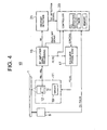
- Fig. 4 is a block diagram of the configuration of a servo control apparatus 10 of an optical disc player according to the present invention.
- the optical disc 1 is rotated by a spindle motor 8.
- the spindle motor 8 is provided with an FG signal generator (not shown) for generating one pulse for each predetermined angle of spindle rotation.
- a generated FG pulse signal is supplied to a controller 23.
- An optical pickup 11 emits a laser light beam on the optical disc 1, receives the light beam reflected from the optical disc 1, and generates a signal in response to the amount of the received light.
- An optical detector 12 provided in the optical pickup 11 is, for example, a 4-partitioned optical detector consisting of four light-receiving elements. Each of the four light-receiving elements receives the light reflected from a beam spot (not shown) , converts it into an electric signal to output as read signals RB 1 -RB 4 , respectively.
- the optical pickup 11 is further provided with a driver 19 comprising a tracking actuator for making the direction of an objective lens (not shown) or the reading point thereof, biased in the radial direction, and a focusing actuator for adjusting the focusing point of the beam spot.
- the optical pickup 11 reads recorded information from the optical disc 1, and supplies the read signals RB 1 - RB 4 to a signal processing circuit 15.
- An RF amplifier is provided in the signal processing circuit 15.
- the RF amplifier amplifies the read signals RB 1 - RB 4 , and extracts a tracking error signal TE and a focus error signal FE based on the amplified read signals. More specifically, the signal processing circuit 15 generates the focus error signal FE using the read signals RB 1 - RB 4 .
- the focus error signal FE is a differential signal between two added signals obtained by adding read signals from the light-receiving elements diagonally opposing each other.
- the signal processing circuit 15 also generates a tracking error signal TE by the phase difference method using the read signals RB 1 - RB 4 , for example.
- the tracking error signal TE and the focus error signal FE generated in the signal processing circuit 15 are supplied to a servo-equalizer (hereinafter, simply referred to as an equalizer) 17.
- a servo-equalizer hereinafter, simply referred to as an equalizer
- the equalizer 17 is a circuit for compensating the amplitude and phase of error signals, such as the tracking error signal TE and the focus error signal FE generated in the signal processing circuit 15. More particularly, the equalizer 17 performs equalization processing on error signals so as to have frequency characteristics suitable for servo control, and supplies the equalized signals to the driver 19 for the optical pickup 11 as drive signals TD and FD, respectively.
- the driver 19 generates actuator operating signals TDRV, FDRV based on the supplied drive signals TD and FD.
- the servo control is performed by operating the actuator in the optical pickup 11.
- a dropout detector 21 for receiving an RF read signal from the signal processing circuit 15 and for detecting defects formed on the optical disc 1, i.e., dropouts in the RF read signal; and a controller 23 for controlling the equalizer 17 in accordance with the dropout detection signal detected by the dropout detector 21, the above-mentioned FG pulse signal, and signals from the signal processing circuit 15.
- the controller 23 is provided with a timer, a memory for storing various data, such as the servo controlled value, the tracking error value, or the focus error value, and an operation section for calculating the coefficient of the equalizer 17 and the like as described below.
- the controller 23 is configured with, for example, a microcomputer or a plurality of circuit blocks.
- a control range is determined in accordance with the transfer function of the actuator and/or the detection sensitivity of the error detectors including the optical system such that the servo does not get out of place even though a disturbance in the servo system such as wobbling rotation of the disc occurs.
- Gain characteristics and phase characteristics are set so that the system operates with stability within the range.
- equalization characteristics are determined so as to secure a sufficient phase margin in the required range of the servo system. More specifically, equalization is performed so as to obtain a sufficient phase margin in the frequency range where the gain characteristics of an open-loop transfer function become 0dB.
- Equalization for focus servo for example, is performed so as to obtain a sufficient phase margin within the frequency range of several hundred hertz to several kilohertz.
- Fig. 5 shows the configuration of the equalizer 17 in the embodiment.
- the tracking error signal TE and the focus error signal FE extracted in the signal processing circuit 15 are supplied to a proportion/differentiation gain multiplier (APD) 31 to be multiplied by a coefficient bearing a predetermined gain.
- the multiplied error signals are supplied to a proportion/differentiation compensator 32 so as to undergo phase compensation.
- APD proportion/differentiation gain multiplier
- the proportion/differentiation compensator 32 is composed of a filter which can shift the phase of an input signal. More specifically, for example, a digital filter of the secondary IIR (infinite impulse response filter) and secondary FIR (finite impulse response filter) type can be used as shown in Fig. 5.
- the digital filter comprises coefficient multipliers 33A-33E, delay elements 34A-34D, and adders 35A-35B.
- the phase compensation characteristics can be changed by altering each of the coefficients A0-A4 of the coefficient multipliers 33A-33E.
- the error signal from the signal processing circuit 15 is also supplied to an integration gain multiplier (AI) 37.
- the integration gain multiplier (AI) 37 multiplies the supplied error signal by a set gain, and supplies it to an integrator 38.
- the integrator 38 is so called a low-pass filter (LPF) including a primary IIR filter.
- LPF low-pass filter
- the integrator 38 is an accumulating circuit for the low-pass components of error signals, and serves as a holding circuit for holding past low-frequency component of the error signals.
- An output signal from the integrator 38 is added to an output signal from the above-mentioned proportion/differentiation compensator 32 at an adder 43, and the signal obtained from the adder is supplied to the driver 19 of the optical pickup 11 as drive signals (TD, FD).
- the integration gain of the integration gain multiplier (AI) 37 increases, the output signal from the integrator 38 increases in magnitude, and the component, which is proportional to the current error, decreases in magnitude relatively.
- the tracking performance to current disturbances for example, an unexpected disturbance such as dropout of an RF signal due to a defect
- the focused state becomes impossible to be maintained due to a deterioration of the tracking performance to disturbances (for example, due to wobbling rotation of the disc) which should essentially be tracked.
- the integration gain and the proportional gain should be determined in respect to the above-mentioned tracking performance to current disturbances.
- the gains of the proportion/differentiation gain multiplier (APD) 31 and the integration gain multiplier (AI) 37 can be changed by a control signal from the controller 23.
- the phase characteristics of the proportion/differentiation compensator 32 can be changed by altering a coefficient of the coefficient multiplier (in the case shown in Fig. 5, coefficient A2, a secondary coefficient, of the coefficient multiplier 33C) by using a control signal from the controller 23.
- the controller 23 generates control signals for the proportion/differentiation gain multiplier (APD) 31, the integration gain multiplier (AI) 37, and the proportion/differentiation compensator 32 based on the amplitude of the envelope signal of the RF read signal.
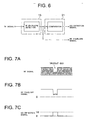
- the envelope signal (Fig. 7B) is extracted from an RF read signal (Fig. 7A) by an envelope detector circuit in the signal processing circuit 15, and supplied to the controller 23.
- the envelope signal is compared with a predetermined discrimination level in a comparator circuit in the dropout detector 21, and a dropout detection signal (Fig. 7C) having a predetermined voltage level (Vd) is generated.
- the generated envelope signal may be supplied to the controller 23 through a suitable low-pass filter (LPF).
- LPF low-pass filter
- step S1 It is determined whether or not any dropout is detected in the controller 23(step S1). For example, it is determined whether or not a dropout has started by a rise (or fall) in the envelope signal. The amplitude of the envelope signal is then sampled in response to the dropout detection signal (step S2).
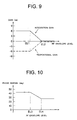
- the controller 23 generates a control signal for changing the gains of the proportional differentiation gain multiplier (APD) 31 and the integration gain multiplier (AI) 37 in accordance with the sampled amplitude. More particularly, when the envelope amplitude value (hereinafter referred to as "envelope level”) is below a predetermined value (EL1), a control signal is generated so as to decrease the proportional gain (-6dB) and increase the integration gain (+6dB) because the reliability of the error signal is low. On the other hand, when the envelope level exceeds another predetermined value EL2 ( ⁇ EL1), the proportional and integration gains are not changed. In other words, a control signal indicating the change value of 0dB is generated.
- envelope level envelope amplitude value
- ⁇ EL1 another predetermined value
- control is performed so as to change the change value of the proportional gain from -6dB to 0dB as the envelope level increases, and at the same time gradually change the integration gain from +6dB to 0dB.
- the controller 23 further generates a control signal for changing the secondary coefficient (A2) of the proportion/differentiation compensator 32 in accordance with the envelope level. More particularly, a control signal is generated for changing the value of the coefficient so as to control transient phenomenon by increasing phase margin when the envelope level is below a first predetermined value (EL3), as is shown in Fig. 10. On the other hand, a control signal is generated to indicate that the phase is not to be changed when the envelope level exceeds a second predetermined value EL4 ( ⁇ EL3). In this manner, a control signal is supplied to the equalizer 17 so as to change the gain and phase in accordance with the envelope level (step S4).
- a control signal is supplied to the equalizer 17 so as to change the gain and phase in accordance with the envelope level (step S4).
- step S5 It is then determined whether or not the dropout is continuing (step S5).
- step S2 When the dropout is continuing, the procedure goes back to step S2 to sample the envelope amplitude, and to repeat the steps described above.
- step S6 whether or not the control for changing the gain and phase is to be continued is determined.
- step S1 the control for changing the gain and phase is to be continued.
- Control exits the process routine when the changing control is not to be continued.
- the gain and phase of the equalizer 17 are controlled in accordance with an amplitude of the envelope signal during the period of time when dropout occurs as described above.
- stable high-precision servo control is realized by changing the gain characteristics and phase characteristics of the equalizer 17 in accordance with the amplitude of the envelope signal during the period when dropout occurs.
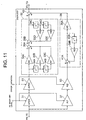
- Fig. 11 is a schematic diagram of the configuration of an equalizer in the servo control apparatus 10 according to a second embodiment of the present invention.
- the equalizer 17 is further provided with a proportion/differentiation gain multiplier (APD2) 51 and a second integration gain multiplier (AI2) 53 so that the gains of the multipliers can be changed by a second control signal from the controller 23.
- APD2 proportion/differentiation gain multiplier
- AI2 integration gain multiplier
- the controller 23 controls the equalization characteristics of the equalizer 17 using a second control signal for changing the integration gain of the second integration gain multiplier (AI2) 53 or the proportional gain of the second proportional differentiation gain multiplier (APD2) 51 in accordance with the change of an error signal in addition to the control signal for changing gains in accordance with the envelope level as described in the first embodiment.
- AI2 integration gain multiplier
- APD2 proportional gain of the second proportional differentiation gain multiplier
- error change a change amount or variance of an error signal (hereinafter, simply referred to as "error change”) defined below is used in order to complement gain control by the envelope level.
- Error change integral value of error (over an angular section of rotation where a dropout occurs) - integral value of error (over the same angular section of rotation before the dropout occurs).
- an integrated or integral value is obtained for an error signal over a range or section of rotational angle (hereinafter, refereed to as an angular section of rotation) on a track before a dropout occurs.
- An integral value is, then, obtained over the same angular section of rotation on a track where a dropout occurs.
- the error change is obtained by subtracting the integral value for the angular section of rotation where a dropout occurs from the integral value before the occurrence of the dropout for the same angular section of rotation.
- the difference between an integral value of the error signal in one period of the FG signal when dropout occurred and an integral value of the error signal in the same FG signal period, i.e., in the same angular section on a different track as that of the former can be used.
- a drive signal may be used instead of the error signal.
- the error change can be generated in the controller 23 as described above.
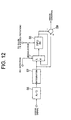
- the generation process of the error change can be performed in circuit blocks shown in Fig. 12.
- an integral value is generated by an integration circuit 57.
- the integral value is supplied to an input terminal on the L terminal of a selector 60 and to a subtracter 59.
- An output terminal of the selector 60 is connected to an FIFO (first-in first-out) memory 58.
- the output from the FIFO memory 58 is supplied to an input H terminal of the selector 60.
- a dropout detection signal is supplied to a control terminal of the selector 60.
- the selector 60 supplies the integral value supplied from the integration circuit 57 selectively to the FIFO memory 58 when the dropout detection signal is on the L level, i.e., when dropout is not detected. Or, the selector 60 supplies an output signal from the FIFO memory 58 selectively to the FIFO memory 58 when the dropout detection signal is on the H level, i.e., when a dropout is detected.
- the FIFO memory 58 consists of N stages of memories.
- An FG pulse signal having N pulses/rotation of the disc is supplied to the FIFO memory 58 through the gate circuit 60.
- the content of the memory 58 is sequentially supplied to the subtracter 59 in response to the FG pulse signal.
- the output from the subtracter 59 is an integral value of the error signal in the current angular section of rotation minus an integral value of the error signal in the same angular section of rotation on a different track.
- the above configuration is designed so that the supply of an integral value of the error signal to the FIFO memory 58 is forbidden and data in the FIFO memory 58 is not updated when a dropout is detected. Consequently, the latest integral value before a dropout is detected is stored in the FIFO memory 58.
- the procedure of control operation performed by the controller 23 is similar to that in the first embodiment except that, in addition to the first control signal for changing gains in accordance with the envelope level, a second control signal for changing gains in accordance with the error change is supplied to the second proportion/differentiation gain multiplier (APD2) 51 and the second integration gain multiplier (AI2) 53 in the equalizer 17. More particularly, as is shown in Fig. 13, the controller 23 decreases the change of the proportional gain as the error change decreases when the error change is below a first predetermined value (EV1) in the negative region (in the case shown in Fig. 13, from 0dB to -0.2dB).
- EV1 first predetermined value
- the controller 23 increases the change of integration gain (from 0dB to 0.4dB) as well as decreases the proportional gain, thus increases the integration gain. Specifically, it is assumed that a normal error signal cannot be obtained due to the dropout (i.e., the error signal is assumed to be nearly 0). Therefore, control is maintained so as not to track the error signal affected by the dropout by increasing the integration gain as well as by decreasing the proportional gain. On the other hand, the change of proportional gain is increased (from 0dB to 0.4dB) as the error change increases when the error change exceeds a second predetermined value (EV2) in the positive region.
- EV2 second predetermined value
- the change of integration gain is decreased (i.e., from 0dB to -0.4dB) at the same time as the proportional gain is increased, thus the integration gain is decreased.
- control is considered to be greatly deviated from the target state due to disturbances caused by the rotation of the disc and the like when an error change exceeds the second predetermined value (EV2) in the positive region.
- the integration gain is decreased so as to improve the tracking performance of the servo control apparatus to the disturbances at the same time as the proportional gain is increased.
- No compensation of the proportional gain and the integration gain is performed (i.e., 0dB) when the error change is between the first predetermined value (EV1) and the second predetermined value (EV2).
- the change of the above gains can be suitably selected in accordance with the servo system or the kind of the disc to be used.
- the present invention is not limited to the case but applicable to various cases.
- the control signal may be determined based on the above error change for changing the characteristics of the proportion/differentiation gain multiplier (APD) 31, the integration gain multiplier (AI) 37, and the proportion/differentiation compensator 32 in the equalizer 17 in Fig. 5, which is used for illustrating the first embodiment.
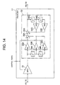
- Another possible design is, as shown in Fig. 14, to change the proportional gain or the phase characteristics of an equalizer having no integration gain multiplier (AI) 37.
- the characteristics of the equalizer 17 are adjusted by comparing the error change at the position on the track (i.e., angular section of rotation) where a dropout occurred with that in the same angular section on the track before the dropout occurred. Accordingly, servo control can be stabilized while a dropout is occurring even though there is a defect at a certain region over a plurality of tracks to cause the dropout of an RF signal. In addition, the transient phenomenon after the disappearance of the dropout can be controlled to realize stable high-precision servo control.
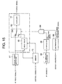
- Fig. 15 is a block diagram illustrating the configuration of a servo control apparatus 10 according to a third embodiment of the present invention. In order to simplify the description, the major part of the configuration of the servo control apparatus 10 is shown in circuit blocks.
- a focus error signal from a focus error detector 61 is supplied to the equalizer 17 through a switch 62, and at the same time, the error value indicated by the focus error signal is supplied to and held in an error value holder 63.
- the switch 62 selectively supplies a focus error signal from the focus error detector 61 or the error value from the error value holder 63 to the equalizer 17 in response to a logical signal from a logical AND circuit 64.
- the switch 62 takes the AND of a dropout detection signal from a comparator 66 and an error change discrimination signal from a discriminator 68 for discriminating whether an error change is below a predetermined value.
- the logical AND circuit 64 sends out a signal of H level when a dropout is detected and the error change is below a predetermined value, and causes the error value from the holder 63 to be supplied to the equalizer 17.
- a control signal from the controller 23 is supplied to a memory 73, and an error value corresponding to the angular section of rotation where the dropout occurred is output from the memory 73 to the holder 63 as a "hold value".
- the held error value may be supplied to the equalizer 17 when a dropout is detected.
- the configuration mentioned above makes it possible to hold the servo control value for an angular section of rotation on a track where a dropout occurred to the value for the same angular section of rotation on a different track before the dropout occurred so as to realize stable high-precision servo control.
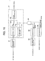
- Fig. 16 is a block diagram illustrating the configuration of a servo control apparatus 10 according to a fourth embodiment of the present invention. In the same manner as for the third embodiment, the major part of the configuration of the servo control apparatus 10 is shown in individual circuit blocks.
- the difference between this embodiment and the above third embodiment is that the equalization characteristics of the equalizer 17 are changed in response to a dropout detection signal and an error change discrimination signal.
- a logical AND operation of a dropout detection signal and an error change discrimination signal are performed in the logic AND circuit 64, and the logical AND signal is supplied to the switch 62.
- the gain of an amplifier 71 in the equalizer 17 is selectively switched to a low gain value during the period when a dropout is detected and the error change is below a predetermined value as shown in Fig. 16.
- FIG. 17 A modification of the embodiment is shown in Fig. 17, wherein the equalization characteristics of the equalizer 17 are changed in response to a dropout detection signal and an error change discrimination signal.
- the phase compensation value of the proportion/differentiation compensator 32 in the equalizer 17 is selectively switched to a second phase compensation value during the period when a dropout is detected and the error change is less than a predetermined value in the embodiment.
- the configuration of the servo control apparatus 10 and the equalizer 17 is similar to that shown in Figs. 4 and 5.
- the equalization characteristics of the equalizer 17 including the gain characteristics and phase compensation characteristics are changed during and after the occurrence of a dropout in order to control the transient phenomenon caused in an error signal due to the occurrence of the dropout.
- the procedure of the control operation is described in detail below.
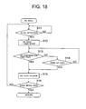
- Fig. 18 is a flowchart of a focus-error-hold operation to be performed by the controller 23.
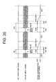
- Fig. 19 is a flowchart of a procedure for changing the equalization characteristics of the equalizer 17. The procedures shown in the flowcharts are performed in parallel with each other. A time chart for illustrating the change of the equalization characteristics of the equalizer 17 is shown in Fig. 20.
- step S11 it is determined whether or not a dropout is detected by the controller 23 (step S11). For example, it is determined whether a dropout has started by the rise (or fall) of an envelope signal. A focus error value FE is then held to a predetermined value (for example, to 0) in response to the dropout detection signal. At the same time, the timer starts time measurement (step S12). During the dropout generation period, a focus error shows a transient oscillation, so the focus-error-hold operation controls the drive signal and stabilizes the operation of the optical pickup.
- step S13 It is then determined whether or not the duration of a dropout has reached a predetermined time (Tdd) (step S13).
- Tdd a predetermined time
- the focus-error-hold operation is released (step S15). This is to prevent servo from becoming unstable because the focus-error hold time being prolonged more than is required may cause the servo to become unstable.
- step S13 if the duration has not reached the predetermined time (Tdd), it is determined whether or not the dropout has terminated (step S14). If the dropout has not terminated, the procedure goes back to step S13. On the other hand, if the dropout has terminated, the procedure goes on to step S15, and the focus-error-hold operation is released.
- step S16 The presence of a control signal indicating the termination of servo control is discriminated (step S16) after the focus-error-hold operation is released in step S 15.
- the procedure goes back to step S11 to repeat the above-mentioned procedures when servo control is to be continued.
- the current routine exits when servo control is to be terminated.
- the equalization characteristics of the equalizer 17 are set to normal gain and phase characteristics, i.e., to the characteristics when no dropout occurs (EQ1) (step S21) by the controller 23. It is then determined whether or not a dropout is detected (step S22).
- the equalization characteristics are changed to the equalization characteristics to be used in a dropout period (EQ2).
- EQ2 dropout period
- Increased phase margin makes the convergence of an error signal waveform and also the rise of an RF signal faster so as to perform stable servo control.
- the change of phase compensation characteristics and gains can be performed by changing the coefficient value of the proportion/differentiation compensator 32 and an integration gain, for example.
- the change of a coefficient value may be performed by table read/write operation in the controller 23.
- step S24 It is then determined whether or not the dropout has terminated (step S24).
- a predetermined time (Tde) has passed since the termination of the dropout (step S25). If the predetermined time (Tde) has passed, a coefficient value is calculated (step S26) for changing the equalization characteristics of the equalizer 17, and the characteristics change is performed based on the calculated coefficient value (step S27). It is then determined whether or not the change of the equalization characteristics from EQ2 to EQ1 has been completed by the change of the coefficient value (step S28). If it has not been completed, the procedure goes back to step S26. As is shown in Fig. 20, the characteristics change is gradually performed from EQ2 to EQ1 by carrying out steps S26-S28 repeatedly.
- step S28 When the change of the equalization characteristics is completed in step S28, the presence of a control signal indicating the termination of servo control is discriminated (step S29). If servo control is to be continued, the procedure goes back to step S22 to repeat the above-mentioned procedures. On the other hand, the current routine exits when servo control is to be terminated.
- the convergence of an error signal waveform is made faster and the transient phenomenon after the occurrence of a dropout is controlled by changing the equalizer's characteristics in response to the occurrence and termination of a dropout or in response to the time which elapsed since the occurrence and termination of a dropout.
- stable high-precision servo control is realized.
- the present invention provides a servo control apparatus which can achieve stable high-precision servo control with a high defect treatment performance.
Landscapes
- Optical Recording Or Reproduction (AREA)
- Moving Of The Head To Find And Align With The Track (AREA)
Applications Claiming Priority (2)
| Application Number | Priority Date | Filing Date | Title |
|---|---|---|---|
| JP2000122468 | 2000-04-24 | ||
| JP2000122468A JP2001307347A (ja) | 2000-04-24 | 2000-04-24 | 光学式ディスクプレーヤのサーボ制御装置及びその方法 |
Publications (3)
| Publication Number | Publication Date |
|---|---|
| EP1152410A2 true EP1152410A2 (fr) | 2001-11-07 |
| EP1152410A3 EP1152410A3 (fr) | 2003-09-03 |
| EP1152410B1 EP1152410B1 (fr) | 2004-10-13 |
Family
ID=18632938
Family Applications (1)
| Application Number | Title | Priority Date | Filing Date |
|---|---|---|---|
| EP01109777A Expired - Lifetime EP1152410B1 (fr) | 2000-04-24 | 2001-04-20 | Appareil de servo commande pour lecteur de disque optique |
Country Status (4)
| Country | Link |
|---|---|
| US (1) | US6738327B2 (fr) |
| EP (1) | EP1152410B1 (fr) |
| JP (1) | JP2001307347A (fr) |
| DE (1) | DE60106320T2 (fr) |
Cited By (2)
| Publication number | Priority date | Publication date | Assignee | Title |
|---|---|---|---|---|
| EP1178486A2 (fr) * | 2000-06-23 | 2002-02-06 | Pioneer Corporation | Appareil de commande d'asservissement pour un entrainement de disque optique |
| WO2002029794A1 (fr) * | 2000-10-04 | 2002-04-11 | Robert Bosch Gmbh | Procede de regulation de la poursuite d'un dispositif de balayage et lecteur a cet effet |
Families Citing this family (7)
| Publication number | Priority date | Publication date | Assignee | Title |
|---|---|---|---|---|
| US6934227B2 (en) * | 2001-09-06 | 2005-08-23 | Matsushita Electric Industrial Co., Ltd. | Optical disk device, semiconductor integrated circuit, pickup control method and vibration component detection method |
| JP3768142B2 (ja) * | 2001-10-24 | 2006-04-19 | 松下電器産業株式会社 | ドロップアウト検出回路及び光ディスク装置 |
| JP4265963B2 (ja) * | 2003-05-15 | 2009-05-20 | パイオニア株式会社 | ピックアップの記録読取点位置の制御装置 |
| JP2007280571A (ja) * | 2006-04-12 | 2007-10-25 | Hitachi Ltd | 光ディスク装置及び再生信号処理方法 |
| US7419224B2 (en) * | 2006-08-11 | 2008-09-02 | Hall David R | Sleeve in a degradation assembly |
| JP2012089198A (ja) * | 2010-10-19 | 2012-05-10 | Sony Corp | 記録装置、制御方法 |
| US8737182B1 (en) * | 2011-11-08 | 2014-05-27 | Marvell International Ltd. | Method and apparatus for measuring eccentricity in rotation of a disc in a disc drive system |
Citations (5)
| Publication number | Priority date | Publication date | Assignee | Title |
|---|---|---|---|---|
| JPS6089836A (ja) * | 1983-10-24 | 1985-05-20 | Toshiba Corp | デイスクレコ−ド再生装置のトラツキング制御回路 |
| US4587644A (en) * | 1982-11-11 | 1986-05-06 | Sony Corporation | Tracking servocontrol circuits for reducing gain to avoid tracking defect in an optical reproducing apparatus |
| US4682314A (en) * | 1982-08-30 | 1987-07-21 | Hitachi, Ltd. | Disc playback apparatus |
| US4736354A (en) * | 1984-11-13 | 1988-04-05 | Pioneer Electronic Corporation | Focus servo device for detecting and compensating for disk abnormalities |
| EP0392561A2 (fr) * | 1989-04-17 | 1990-10-17 | Mitsubishi Denki Kabushiki Kaisha | Unité de disque optique |
Family Cites Families (1)
| Publication number | Priority date | Publication date | Assignee | Title |
|---|---|---|---|---|
| JPH04345944A (ja) * | 1991-05-24 | 1992-12-01 | Sony Corp | データ再生装置 |
-
2000
- 2000-04-24 JP JP2000122468A patent/JP2001307347A/ja active Pending
-
2001
- 2001-04-18 US US09/836,235 patent/US6738327B2/en not_active Expired - Fee Related
- 2001-04-20 EP EP01109777A patent/EP1152410B1/fr not_active Expired - Lifetime
- 2001-04-20 DE DE60106320T patent/DE60106320T2/de not_active Expired - Fee Related
Patent Citations (5)
| Publication number | Priority date | Publication date | Assignee | Title |
|---|---|---|---|---|
| US4682314A (en) * | 1982-08-30 | 1987-07-21 | Hitachi, Ltd. | Disc playback apparatus |
| US4587644A (en) * | 1982-11-11 | 1986-05-06 | Sony Corporation | Tracking servocontrol circuits for reducing gain to avoid tracking defect in an optical reproducing apparatus |
| JPS6089836A (ja) * | 1983-10-24 | 1985-05-20 | Toshiba Corp | デイスクレコ−ド再生装置のトラツキング制御回路 |
| US4736354A (en) * | 1984-11-13 | 1988-04-05 | Pioneer Electronic Corporation | Focus servo device for detecting and compensating for disk abnormalities |
| EP0392561A2 (fr) * | 1989-04-17 | 1990-10-17 | Mitsubishi Denki Kabushiki Kaisha | Unité de disque optique |
Non-Patent Citations (1)
| Title |
|---|
| PATENT ABSTRACTS OF JAPAN vol. 009, no. 236 (P-390), 21 September 1985 (1985-09-21) -& JP 60 089836 A (TOSHIBA KK), 20 May 1985 (1985-05-20) * |
Cited By (3)
| Publication number | Priority date | Publication date | Assignee | Title |
|---|---|---|---|---|
| EP1178486A2 (fr) * | 2000-06-23 | 2002-02-06 | Pioneer Corporation | Appareil de commande d'asservissement pour un entrainement de disque optique |
| EP1178486A3 (fr) * | 2000-06-23 | 2004-03-31 | Pioneer Corporation | Appareil de commande d'asservissement pour un entrainement de disque optique |
| WO2002029794A1 (fr) * | 2000-10-04 | 2002-04-11 | Robert Bosch Gmbh | Procede de regulation de la poursuite d'un dispositif de balayage et lecteur a cet effet |
Also Published As
| Publication number | Publication date |
|---|---|
| DE60106320T2 (de) | 2006-02-23 |
| US6738327B2 (en) | 2004-05-18 |
| DE60106320D1 (de) | 2004-11-18 |
| EP1152410A3 (fr) | 2003-09-03 |
| JP2001307347A (ja) | 2001-11-02 |
| EP1152410B1 (fr) | 2004-10-13 |
| US20020001265A1 (en) | 2002-01-03 |
Similar Documents
| Publication | Publication Date | Title |
|---|---|---|
| US6249494B1 (en) | Disk type determining apparatus, optical disk reproducing apparatus and tracking error signal generating apparatus | |
| EP0612063B1 (fr) | Dispositif et méthode d'équilibrage automatique d'un détecteur d'écart de focalisation | |
| EP1003159A1 (fr) | Dispositif d'entraínement pour support d'enregistrement optique | |
| US6888782B2 (en) | Servo controller having unit for compensating error signal during dropout | |
| US4786849A (en) | Offset compensating circuit in fine control servo device | |
| US20070008838A1 (en) | Disc driving apparatus and information readout method | |
| EP1152410B1 (fr) | Appareil de servo commande pour lecteur de disque optique | |
| US6646962B2 (en) | Apparatus for detecting dropout, an error signal extracting unit, and unit for identifying type of dropout in an optical pickup | |
| JP2001312828A (ja) | 光学式ディスクプレーヤのサーボ制御装置 | |
| JP2007095154A (ja) | 光ディスク記録再生装置 | |
| JP4329772B2 (ja) | 光ディスク装置 | |
| KR100272366B1 (ko) | 디스크판별방법 | |
| KR100533749B1 (ko) | 광디스크 재생기의 등화계수 조절장치 및 방법 | |
| US7525884B2 (en) | Position control apparatus and method for an optical disk recording/reproducing apparatus with interlinked on/off of a phase compensator and on/off of a servo loop | |
| US7583571B2 (en) | Write based power adaptive control system | |
| KR100556495B1 (ko) | 광 디스크 기록 재생 방법 및 장치 | |
| JPH08255360A (ja) | 光ディスク装置 | |
| JP2003317288A (ja) | 光ディスク装置及びディスクチルト検出方法 | |
| JP3465747B2 (ja) | フォーカスサーボ回路 | |
| JP2007234183A (ja) | 光ディスク装置 | |
| JPH06187645A (ja) | 光ディスクのトラッキング制御装置 | |
| KR100233651B1 (ko) | 광디스크 재생기록장치의 포커스바이어스 조정방법 | |
| JPH0438630A (ja) | 光ディスク装置 | |
| JPH0660385A (ja) | コンパクトディスクプレーヤ装置 | |
| KR20060067634A (ko) | 광 디스크 재생 장치의 트랙킹 서보 제어 방법 |
Legal Events
| Date | Code | Title | Description |
|---|---|---|---|
| PUAI | Public reference made under article 153(3) epc to a published international application that has entered the european phase |
Free format text: ORIGINAL CODE: 0009012 |
|
| AK | Designated contracting states |
Kind code of ref document: A2 Designated state(s): AT BE CH CY DE DK ES FI FR GB GR IE IT LI LU MC NL PT SE TR |
|
| AX | Request for extension of the european patent |
Free format text: AL;LT;LV;MK;RO;SI |
|
| PUAL | Search report despatched |
Free format text: ORIGINAL CODE: 0009013 |
|
| AK | Designated contracting states |
Kind code of ref document: A3 Designated state(s): AT BE CH CY DE DK ES FI FR GB GR IE IT LI LU MC NL PT SE TR |
|
| AX | Request for extension of the european patent |
Extension state: AL LT LV MK RO SI |
|
| 17P | Request for examination filed |
Effective date: 20030903 |
|
| GRAP | Despatch of communication of intention to grant a patent |
Free format text: ORIGINAL CODE: EPIDOSNIGR1 |
|
| AKX | Designation fees paid |
Designated state(s): DE FR GB |
|
| GRAS | Grant fee paid |
Free format text: ORIGINAL CODE: EPIDOSNIGR3 |
|
| GRAA | (expected) grant |
Free format text: ORIGINAL CODE: 0009210 |
|
| AK | Designated contracting states |
Kind code of ref document: B1 Designated state(s): DE FR GB |
|
| REG | Reference to a national code |
Ref country code: GB Ref legal event code: FG4D |
|
| REG | Reference to a national code |
Ref country code: IE Ref legal event code: FG4D |
|
| REF | Corresponds to: |
Ref document number: 60106320 Country of ref document: DE Date of ref document: 20041118 Kind code of ref document: P |
|
| REG | Reference to a national code |
Ref country code: GB Ref legal event code: 746 Effective date: 20050224 |
|
| PLBE | No opposition filed within time limit |
Free format text: ORIGINAL CODE: 0009261 |
|
| STAA | Information on the status of an ep patent application or granted ep patent |
Free format text: STATUS: NO OPPOSITION FILED WITHIN TIME LIMIT |
|
| ET | Fr: translation filed | ||
| 26N | No opposition filed |
Effective date: 20050714 |
|
| REG | Reference to a national code |
Ref country code: FR Ref legal event code: D6 |
|
| PGFP | Annual fee paid to national office [announced via postgrant information from national office to epo] |
Ref country code: FR Payment date: 20060411 Year of fee payment: 6 |
|
| PGFP | Annual fee paid to national office [announced via postgrant information from national office to epo] |
Ref country code: GB Payment date: 20060420 Year of fee payment: 6 |
|
| PGFP | Annual fee paid to national office [announced via postgrant information from national office to epo] |
Ref country code: DE Payment date: 20060630 Year of fee payment: 6 |
|
| GBPC | Gb: european patent ceased through non-payment of renewal fee |
Effective date: 20070420 |
|
| PG25 | Lapsed in a contracting state [announced via postgrant information from national office to epo] |
Ref country code: DE Free format text: LAPSE BECAUSE OF NON-PAYMENT OF DUE FEES Effective date: 20071101 |
|
| PG25 | Lapsed in a contracting state [announced via postgrant information from national office to epo] |
Ref country code: GB Free format text: LAPSE BECAUSE OF NON-PAYMENT OF DUE FEES Effective date: 20070420 |
|
| PG25 | Lapsed in a contracting state [announced via postgrant information from national office to epo] |
Ref country code: FR Free format text: LAPSE BECAUSE OF NON-PAYMENT OF DUE FEES Effective date: 20070430 |