EP1151904A1 - Dispositif et procédé de ventilation d'équipements électriques embarqués à bord d'un véhicule ferroviaire - Google Patents
Dispositif et procédé de ventilation d'équipements électriques embarqués à bord d'un véhicule ferroviaire Download PDFInfo
- Publication number
- EP1151904A1 EP1151904A1 EP01400976A EP01400976A EP1151904A1 EP 1151904 A1 EP1151904 A1 EP 1151904A1 EP 01400976 A EP01400976 A EP 01400976A EP 01400976 A EP01400976 A EP 01400976A EP 1151904 A1 EP1151904 A1 EP 1151904A1
- Authority
- EP
- European Patent Office
- Prior art keywords
- electrical equipment
- fan
- converter
- supplied
- controlled
- Prior art date
- Legal status (The legal status is an assumption and is not a legal conclusion. Google has not performed a legal analysis and makes no representation as to the accuracy of the status listed.)
- Granted
Links
Images
Classifications
-
- B—PERFORMING OPERATIONS; TRANSPORTING
- B61—RAILWAYS
- B61C—LOCOMOTIVES; MOTOR RAILCARS
- B61C17/00—Arrangement or disposition of parts; Details or accessories not otherwise provided for; Use of control gear and control systems
-
- B—PERFORMING OPERATIONS; TRANSPORTING
- B61—RAILWAYS
- B61C—LOCOMOTIVES; MOTOR RAILCARS
- B61C17/00—Arrangement or disposition of parts; Details or accessories not otherwise provided for; Use of control gear and control systems
- B61C17/04—Arrangement or disposition of driving cabins, footplates or engine rooms; Ventilation thereof
-
- F—MECHANICAL ENGINEERING; LIGHTING; HEATING; WEAPONS; BLASTING
- F04—POSITIVE - DISPLACEMENT MACHINES FOR LIQUIDS; PUMPS FOR LIQUIDS OR ELASTIC FLUIDS
- F04D—NON-POSITIVE-DISPLACEMENT PUMPS
- F04D25/00—Pumping installations or systems
- F04D25/02—Units comprising pumps and their driving means
- F04D25/06—Units comprising pumps and their driving means the pump being electrically driven
-
- F—MECHANICAL ENGINEERING; LIGHTING; HEATING; WEAPONS; BLASTING
- F04—POSITIVE - DISPLACEMENT MACHINES FOR LIQUIDS; PUMPS FOR LIQUIDS OR ELASTIC FLUIDS
- F04D—NON-POSITIVE-DISPLACEMENT PUMPS
- F04D25/00—Pumping installations or systems
- F04D25/02—Units comprising pumps and their driving means
- F04D25/08—Units comprising pumps and their driving means the working fluid being air, e.g. for ventilation
-
- H—ELECTRICITY
- H02—GENERATION; CONVERSION OR DISTRIBUTION OF ELECTRIC POWER
- H02M—APPARATUS FOR CONVERSION BETWEEN AC AND AC, BETWEEN AC AND DC, OR BETWEEN DC AND DC, AND FOR USE WITH MAINS OR SIMILAR POWER SUPPLY SYSTEMS; CONVERSION OF DC OR AC INPUT POWER INTO SURGE OUTPUT POWER; CONTROL OR REGULATION THEREOF
- H02M7/00—Conversion of ac power input into dc power output; Conversion of dc power input into ac power output
- H02M7/42—Conversion of dc power input into ac power output without possibility of reversal
-
- H—ELECTRICITY
- H05—ELECTRIC TECHNIQUES NOT OTHERWISE PROVIDED FOR
- H05K—PRINTED CIRCUITS; CASINGS OR CONSTRUCTIONAL DETAILS OF ELECTRIC APPARATUS; MANUFACTURE OF ASSEMBLAGES OF ELECTRICAL COMPONENTS
- H05K7/00—Constructional details common to different types of electric apparatus
- H05K7/20—Modifications to facilitate cooling, ventilating, or heating
- H05K7/20009—Modifications to facilitate cooling, ventilating, or heating using a gaseous coolant in electronic enclosures
- H05K7/20136—Forced ventilation, e.g. by fans
- H05K7/20172—Fan mounting or fan specifications
-
- B—PERFORMING OPERATIONS; TRANSPORTING
- B60—VEHICLES IN GENERAL
- B60L—PROPULSION OF ELECTRICALLY-PROPELLED VEHICLES; SUPPLYING ELECTRIC POWER FOR AUXILIARY EQUIPMENT OF ELECTRICALLY-PROPELLED VEHICLES; ELECTRODYNAMIC BRAKE SYSTEMS FOR VEHICLES IN GENERAL; MAGNETIC SUSPENSION OR LEVITATION FOR VEHICLES; MONITORING OPERATING VARIABLES OF ELECTRICALLY-PROPELLED VEHICLES; ELECTRIC SAFETY DEVICES FOR ELECTRICALLY-PROPELLED VEHICLES
- B60L2200/00—Type of vehicles
- B60L2200/26—Rail vehicles
-
- H—ELECTRICITY
- H02—GENERATION; CONVERSION OR DISTRIBUTION OF ELECTRIC POWER
- H02K—DYNAMO-ELECTRIC MACHINES
- H02K17/00—Asynchronous induction motors; Asynchronous induction generators
-
- H—ELECTRICITY
- H02—GENERATION; CONVERSION OR DISTRIBUTION OF ELECTRIC POWER
- H02K—DYNAMO-ELECTRIC MACHINES
- H02K7/00—Arrangements for handling mechanical energy structurally associated with dynamo-electric machines, e.g. structural association with mechanical driving motors or auxiliary dynamo-electric machines
- H02K7/14—Structural association with mechanical loads, e.g. with hand-held machine tools or fans
-
- H—ELECTRICITY
- H02—GENERATION; CONVERSION OR DISTRIBUTION OF ELECTRIC POWER
- H02K—DYNAMO-ELECTRIC MACHINES
- H02K9/00—Arrangements for cooling or ventilating
- H02K9/02—Arrangements for cooling or ventilating by ambient air flowing through the machine
- H02K9/04—Arrangements for cooling or ventilating by ambient air flowing through the machine having means for generating a flow of cooling medium
-
- Y—GENERAL TAGGING OF NEW TECHNOLOGICAL DEVELOPMENTS; GENERAL TAGGING OF CROSS-SECTIONAL TECHNOLOGIES SPANNING OVER SEVERAL SECTIONS OF THE IPC; TECHNICAL SUBJECTS COVERED BY FORMER USPC CROSS-REFERENCE ART COLLECTIONS [XRACs] AND DIGESTS
- Y02—TECHNOLOGIES OR APPLICATIONS FOR MITIGATION OR ADAPTATION AGAINST CLIMATE CHANGE
- Y02T—CLIMATE CHANGE MITIGATION TECHNOLOGIES RELATED TO TRANSPORTATION
- Y02T10/00—Road transport of goods or passengers
- Y02T10/60—Other road transportation technologies with climate change mitigation effect
- Y02T10/64—Electric machine technologies in electromobility
-
- Y—GENERAL TAGGING OF NEW TECHNOLOGICAL DEVELOPMENTS; GENERAL TAGGING OF CROSS-SECTIONAL TECHNOLOGIES SPANNING OVER SEVERAL SECTIONS OF THE IPC; TECHNICAL SUBJECTS COVERED BY FORMER USPC CROSS-REFERENCE ART COLLECTIONS [XRACs] AND DIGESTS
- Y02—TECHNOLOGIES OR APPLICATIONS FOR MITIGATION OR ADAPTATION AGAINST CLIMATE CHANGE
- Y02T—CLIMATE CHANGE MITIGATION TECHNOLOGIES RELATED TO TRANSPORTATION
- Y02T30/00—Transportation of goods or passengers via railways, e.g. energy recovery or reducing air resistance
Definitions
- the invention relates to a device and a method for ventilating equipment. on board a railway vehicle supplied with direct current and more particularly to a ventilation device comprising for each of the electrical equipment, an associated fan controlled by an electric motor.
- the ventilation device preferably applies to traction vehicles railways for which on-board ventilated electrical equipment is numerous.
- each power equipment of a powerplant such as transformers, traction motors, braking rheostats or blocks power electronics are individually cooled by means of a fan driven by an electric motor, all of these motors being supplied with electricity by the same converter ensuring the transformation, on board the drive, direct current available at the catenary in a suitable alternating current for the operation of power equipment.
- a device ventilation has the disadvantage of causing a collective operation of different fans. So as soon as only one of the fans has operate at full power, to cool equipment associated with it, the other fans are also fully powered power through the converter, which unnecessarily increases the energy consumption and generate additional noise pollution.
- the object of the present invention is therefore to propose a device and a method for ventilation of electrical equipment on board a railway vehicle, which provides increased comfort to the rail vehicle by reducing nuisance which ensures reduced energy consumption.
- the subject of the invention is a device for ventilating electrical equipment. on board a railway vehicle, the latter being supplied with current continuous either directly by a current sensor system connected to a source of direct current, either indirectly by rectification and filtering of a current picked up by a current sensor system connected to a single-phase alternating current source, each electrical equipment being ventilated by means of a fan cooling controlled by an electric motor, characterized in that the electric motors are asynchronous motors, each electric motor of fan being supplied with three-phase alternating current by a converter individual connected to the direct current of supply of the railway vehicle.
- the invention also relates to a method of ventilating electrical equipment. on board a railway vehicle supplied with direct current, each of the electrical equipment being ventilated by means of a cooling fan controlled by an electric motor, characterized in that each electric motor fan is supplied with three-phase alternating current independently at by means of an individual converter connected to the direct supply current of the railway vehicle, the converter being controlled as a function of the power consumed by associated electrical equipment;
- each converter is controlled so that the cooling of the associated electrical equipment is proportional to the power consumed by the electrical equipment.
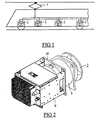
- Figure 1 shows a rail vehicle power train electric by means of a pantograph device 1 connected to a catenary supplying direct current at a voltage of 750V.
- the powerplant is equipped with electrical equipment from type traction motor, transformer, electronic power unit or rheostat braking, each comprising a cooling fan 2 driven in rotation by an asynchronous electric motor 3.
- a current converter 4 is integrated into the frame of each asynchronous motor 3 so as to ensure the transformation of the current direct 750V catenary in three-phase alternating current supplying the motor 3 asynchronous.
- the converter 4 is fixed by screws on a flange 31 of the frame of the electric motor 3 thus making it possible to obtain a 4-motor converter assembly 3 - fan 2 can be bulky.
- the winding of each electric motor 3 is dimensioned to operate directly at the fundamental output voltage of the converters, ie 545V / 50Hz.
- Each converter 4 comprises a control circuit receiving, as input parameter, the value of the current consumed by the electrical equipment at ventilate.
- the operation of the ventilation device according to the invention is as follows:
- fan motor 3 2 associated cooling system is supplied with alternating current by the integrated converter 4, the latter based on the reading of the current consumed by the electrical equipment to proportionally power the electric motor 3 so that the speed of rotation of fan 2 is proportional to the consumption associated electrical equipment.
- Such a ventilation device comprising asynchronous motors for the fan drive has the advantage of having a lifetime and a higher reliability than devices with DC motors while requiring less maintenance.
- the presence of a converter integrated into each fan motor allows individual modulation of the power of each fan as a function of the electrical power consumed by electrical equipment and therefore the heat given off by the latter.
- the ventilation device according to the invention makes it possible to adapt the ventilation of each electrical equipment according to the needs of cooling and thus considerably reduces consumption of energy. Furthermore, the ventilation device and method according to the invention also have the advantage, allowing individual control of the fans electrical equipment, limit the operating time of the fans thus reducing the noise pollution emitted by them and therefore providing a greater comfort for passengers.
Landscapes
- Engineering & Computer Science (AREA)
- Mechanical Engineering (AREA)
- Automation & Control Theory (AREA)
- Transportation (AREA)
- General Engineering & Computer Science (AREA)
- Microelectronics & Electronic Packaging (AREA)
- Physics & Mathematics (AREA)
- Thermal Sciences (AREA)
- Power Engineering (AREA)
- Electric Propulsion And Braking For Vehicles (AREA)
- Inverter Devices (AREA)
- Motor Or Generator Cooling System (AREA)
- Cooling Or The Like Of Electrical Apparatus (AREA)
- Control Of Multiple Motors (AREA)
- Linear Motors (AREA)
- Air-Conditioning For Vehicles (AREA)
Abstract
Description
- le convertisseur individuel est intégré sur le bâti du moteur de ventilateur ;
- chaque convertisseur d'alimentation des ventilateurs est piloté en fonction de la puissance consommée par l'équipement électrique associé ;
- le véhicule ferroviaire est une motrice comportant des équipements électriques de puissance tels que des transformateurs, des moteurs de traction, des rhéostats de freinage ou des blocs électronique de puissance.
- la figure 1 est une représentation schématique en vue de côté d'un véhicule ferroviaire muni d'un dispositif de ventilation d'équipements électriques embarqués selon l'invention ;
- la figure 2 est une vue en perspective d'un moteur de ventilation intégrant un convertisseur utilisé dans le dispositif de ventilation selon l'invention .
Claims (6)
- Dispositif de ventilation d'équipements électriques embarqués à bord d'un véhicule ferroviaire, ledit véhicule ferroviaire étant alimenté en courant continu soit directement par un système capteur de courant (1) relié à une source de courant continu, soit indirectement par redressage et filtrage d'un courant capté par un système capteur de courant (1) relié à une source de courant alternatif monophasé, chaque équipement électrique étant ventilé au moyen d'un ventilateur de refroidissement (2) commandé par un moteur électrique (3), caractérisé en ce que les moteurs électriques (3) sont des moteurs asynchrone, chaque moteur électrique (3) de ventilateur (2) étant alimenté en courant alternatif triphasé par un convertisseur individuel (4) relié au courant continu d'alimentation du véhicule ferroviaire.
- Dispositif de ventilation selon la revendication 1, caractérisé en ce que ledit convertisseur individuel (4) est intégré sur le bâti dudit moteur de ventilateur (2).
- Dispositif selon la revendication 2, caractérisé en ce que chaque convertisseur d'alimentation des ventilateurs (2) est piloté en fonction de la puissance consommée par ledit équipement électrique associé.
- Dispositif selon l'une quelconque des revendications 1 à 3, caractérisé en ce que ledit véhicule ferroviaire est une motrice comportant des équipements électriques de puissance tels que des transformateurs, des moteurs de traction, des rhéostats de freinage ou des blocs électronique de puissance.
- Procédé de ventilation d'équipements électriques embarqués à bord d'un véhicule ferroviaire alimenté en courant continu, chacun desdits équipements électriques étant ventilé au moyen d'un ventilateur de refroidissement (2) commandé par un moteur électrique (3), caractérisé en ce que les moteurs électriques (3) sont des moteurs asynchrone, chaque moteur électrique (3) de ventilateur (2) étant alimenté en courant alternatif triphasé de façon indépendante au moyen d'un convertisseur individuel relié au courant continu d'alimentation du véhicule ferroviaire, ledit convertisseur (4) individuel étant piloté en fonction de la puissance consommée par l'équipement électrique associé.
- Procédé de ventilation selon la revendication précédente, caractérisé en ce que chaque convertisseur est piloté de façon à ce que le refroidissement de l'équipement électrique associé soit proportionnel à la puissance consommée par ledit équipement électrique.
Applications Claiming Priority (2)
| Application Number | Priority Date | Filing Date | Title |
|---|---|---|---|
| FR0005746A FR2808487B1 (fr) | 2000-05-04 | 2000-05-04 | Dispositif et procede de ventilation d'equipements electriques embarques a bord d'un vehicule ferroviaire |
| FR0005746 | 2000-05-04 |
Publications (2)
| Publication Number | Publication Date |
|---|---|
| EP1151904A1 true EP1151904A1 (fr) | 2001-11-07 |
| EP1151904B1 EP1151904B1 (fr) | 2005-08-10 |
Family
ID=8849918
Family Applications (1)
| Application Number | Title | Priority Date | Filing Date |
|---|---|---|---|
| EP01400976A Expired - Lifetime EP1151904B1 (fr) | 2000-05-04 | 2001-04-13 | Dispositif et procédé de ventilation d'équipements électriques embarqués à bord d'un véhicule ferroviaire |
Country Status (17)
| Country | Link |
|---|---|
| US (1) | US6431081B2 (fr) |
| EP (1) | EP1151904B1 (fr) |
| JP (1) | JP2002019608A (fr) |
| KR (1) | KR100694754B1 (fr) |
| CN (1) | CN1274527C (fr) |
| AT (1) | ATE301568T1 (fr) |
| AU (1) | AU765963B2 (fr) |
| BR (1) | BR0101671A (fr) |
| CA (1) | CA2346314C (fr) |
| CZ (1) | CZ301328B6 (fr) |
| DE (1) | DE60112504T2 (fr) |
| FR (1) | FR2808487B1 (fr) |
| HK (1) | HK1051518A1 (fr) |
| MX (1) | MXPA01004472A (fr) |
| PL (1) | PL200983B1 (fr) |
| RU (1) | RU2238856C2 (fr) |
| TW (1) | TW555661B (fr) |
Cited By (1)
| Publication number | Priority date | Publication date | Assignee | Title |
|---|---|---|---|---|
| FR3070353A1 (fr) * | 2017-08-30 | 2019-03-01 | Speedinnov | Motrice de train a grande vitesse |
Families Citing this family (12)
| Publication number | Priority date | Publication date | Assignee | Title |
|---|---|---|---|---|
| FR2902049B1 (fr) * | 2006-06-09 | 2008-09-05 | Alstom Transport Sa | Systeme et procede d'alimentation pour un vehicule ferroviaire, convertisseur, unite de pilotage, climatiseur pour ce systeme |
| US20070285889A1 (en) * | 2006-06-12 | 2007-12-13 | Watson Mark A | Forced air cooled electrical box for mining equipment |
| KR100781140B1 (ko) * | 2006-10-09 | 2007-11-30 | 임효진 | 철도차량용 환기장치 |
| DE102007060893A1 (de) * | 2007-12-14 | 2009-06-25 | Bombardier Transportation Gmbh | Anordnung zur Versorgung von Einrichtungen einer Lokomotive mit elektrischer Energie und Verfahren zum Betreiben der Anordnung |
| DE102010041440A1 (de) * | 2010-09-27 | 2012-03-29 | Siemens Aktiengesellschaft | Fahrzeug mit einer mit Hilfe eines Kühlluftmassenstrms gekühlten Komponente |
| WO2013098879A1 (fr) | 2011-12-27 | 2013-07-04 | 三菱電機株式会社 | Dispositif de climatisation pour véhicule |
| CN102710756B (zh) * | 2012-05-18 | 2015-06-10 | 中国铁道科学研究院基础设施检测研究所 | 接触网检测数据的实时同步方法及处理方法 |
| CA2944371C (fr) * | 2014-06-05 | 2020-03-24 | Rittal Gmbh & Co. Kg | Appareil frigorifique, destine en particulier a refroidir des composants loges dans une armoire electrique, utilisation correspondante et procede correspondant |
| FR3070354B1 (fr) * | 2017-08-30 | 2019-09-13 | Speedinnov | Motrice de train a grande vitesse avec surpression interne |
| CN110304085B (zh) * | 2019-06-21 | 2020-08-14 | 常州大学 | 一种高铁紧急状态停车车厢通风散热装置 |
| CN113442955A (zh) * | 2021-07-01 | 2021-09-28 | 中车青岛四方车辆研究所有限公司 | 一种有轨电车车顶逆变器箱 |
| CN115898916A (zh) * | 2022-11-16 | 2023-04-04 | 阳光电源股份有限公司 | 一种风扇系统、逆变器及控制方法 |
Citations (3)
| Publication number | Priority date | Publication date | Assignee | Title |
|---|---|---|---|---|
| EP0073846A1 (fr) * | 1981-09-03 | 1983-03-16 | Fried. Krupp Gesellschaft mit beschränkter Haftung | Dispositif de réglage de la vitesse d'un moteur à courant triphase à ventilateurs d'une installation de conditionnement d'air |
| DE3231152A1 (de) * | 1981-08-27 | 1983-08-04 | Robert Bosch Gmbh, 7000 Stuttgart | Fremdbeluefteter wechselstromgenerator, insbesondere als drehstromgenerator |
| US4831294A (en) * | 1986-12-23 | 1989-05-16 | Kone Oy | Air cooled electromechanical drive apparatus |
Family Cites Families (16)
| Publication number | Priority date | Publication date | Assignee | Title |
|---|---|---|---|---|
| US2082230A (en) * | 1934-08-28 | 1937-06-01 | Pullman Standard Car Mfg Co | Engine cooling and air conditioning system for self-propelled vehicles |
| US2164444A (en) * | 1937-01-02 | 1939-07-04 | Gen Motors Corp | Cooling of railway traction motors |
| SE7500545L (sv) * | 1975-01-20 | 1976-07-21 | Asea Ab | Likstromsmatad drivutrustning |
| JPS5843161A (ja) * | 1981-08-27 | 1983-03-12 | ロ−ベルト・ボツシユ・ゲゼルシヤフト・ミツト・ベシユレンクテル・ハフツング | 外部送風冷却式交流発電機 |
| JPH01141163A (ja) * | 1986-02-11 | 1989-06-02 | Alsthom Atlantique Sa | 機関車の流体冷却器用及び/又は加減抵抗器用換気装置 |
| JPS63174501A (ja) * | 1987-01-14 | 1988-07-19 | Toshiba Corp | 電気車の制御装置 |
| JPH0274192A (ja) * | 1988-09-08 | 1990-03-14 | Toshiba Corp | 電力変換装置 |
| JPH04334901A (ja) * | 1991-05-13 | 1992-11-24 | Toshiba Corp | 電気車の電源装置 |
| EP0587818B1 (fr) * | 1991-06-03 | 1994-11-02 | Siemens Aktiengesellschaft | Ensemble ventilateur |
| DE9415770U1 (de) * | 1994-09-30 | 1994-12-15 | Abb Henschell Ag | Schienengebundenes Dieseltriebfahrzeug |
| US5646510A (en) * | 1995-03-31 | 1997-07-08 | General Electric Company | AC locomotive operation with DC bus current sensor failure |
| DE19611401C2 (de) * | 1996-03-22 | 2000-05-31 | Danfoss As | Frequenzumrichter für einen Elektromotor |
| DE19624090C1 (de) * | 1996-06-17 | 1997-10-02 | Siemens Ag | Einspeiseschaltung für eine Mehrsystem-Traktionseinrichtung |
| DE59712901D1 (de) * | 1997-08-18 | 2008-01-24 | Alstom Technology Ltd | Verfahren zur Versorgung einer Gasturbinenanlage |
| DE19817752B4 (de) * | 1998-04-21 | 2004-08-26 | Siemens Ag | Elektrische Schaltungsanordnung zum Versorgen eines elektrischen Antriebssystems |
| US20080121136A1 (en) * | 2006-11-28 | 2008-05-29 | General Electric Company | Hybrid locomotive and method of operating the same |
-
2000
- 2000-05-04 FR FR0005746A patent/FR2808487B1/fr not_active Expired - Fee Related
-
2001
- 2001-04-13 EP EP01400976A patent/EP1151904B1/fr not_active Expired - Lifetime
- 2001-04-13 DE DE60112504T patent/DE60112504T2/de not_active Expired - Fee Related
- 2001-04-13 AT AT01400976T patent/ATE301568T1/de not_active IP Right Cessation
- 2001-04-24 US US09/840,021 patent/US6431081B2/en not_active Expired - Fee Related
- 2001-04-27 PL PL347302A patent/PL200983B1/pl not_active IP Right Cessation
- 2001-04-30 CN CNB011167874A patent/CN1274527C/zh not_active Expired - Fee Related
- 2001-04-30 AU AU38982/01A patent/AU765963B2/en not_active Ceased
- 2001-05-01 CA CA002346314A patent/CA2346314C/fr not_active Expired - Fee Related
- 2001-05-01 JP JP2001134249A patent/JP2002019608A/ja not_active Withdrawn
- 2001-05-03 MX MXPA01004472A patent/MXPA01004472A/es active IP Right Grant
- 2001-05-03 RU RU2001112229A patent/RU2238856C2/ru active
- 2001-05-03 KR KR1020010024055A patent/KR100694754B1/ko not_active IP Right Cessation
- 2001-05-03 BR BR0101671-7A patent/BR0101671A/pt not_active IP Right Cessation
- 2001-05-03 TW TW090110647A patent/TW555661B/zh not_active IP Right Cessation
- 2001-05-04 CZ CZ20011588A patent/CZ301328B6/cs not_active IP Right Cessation
-
2003
- 2003-05-30 HK HK03103857A patent/HK1051518A1/xx not_active IP Right Cessation
Patent Citations (3)
| Publication number | Priority date | Publication date | Assignee | Title |
|---|---|---|---|---|
| DE3231152A1 (de) * | 1981-08-27 | 1983-08-04 | Robert Bosch Gmbh, 7000 Stuttgart | Fremdbeluefteter wechselstromgenerator, insbesondere als drehstromgenerator |
| EP0073846A1 (fr) * | 1981-09-03 | 1983-03-16 | Fried. Krupp Gesellschaft mit beschränkter Haftung | Dispositif de réglage de la vitesse d'un moteur à courant triphase à ventilateurs d'une installation de conditionnement d'air |
| US4831294A (en) * | 1986-12-23 | 1989-05-16 | Kone Oy | Air cooled electromechanical drive apparatus |
Cited By (4)
| Publication number | Priority date | Publication date | Assignee | Title |
|---|---|---|---|---|
| FR3070353A1 (fr) * | 2017-08-30 | 2019-03-01 | Speedinnov | Motrice de train a grande vitesse |
| CN109421757A (zh) * | 2017-08-30 | 2019-03-05 | 速度创新公司 | 用于高速列车的动力车厢 |
| EP3453584A1 (fr) * | 2017-08-30 | 2019-03-13 | SpeedInnov | Motrice de train à grande vitesse |
| CN109421757B (zh) * | 2017-08-30 | 2021-09-07 | 速度创新公司 | 用于高速列车的动力车厢 |
Also Published As
| Publication number | Publication date |
|---|---|
| CA2346314A1 (fr) | 2001-11-04 |
| TW555661B (en) | 2003-10-01 |
| US6431081B2 (en) | 2002-08-13 |
| DE60112504D1 (de) | 2005-09-15 |
| PL347302A1 (en) | 2001-11-05 |
| US20010050025A1 (en) | 2001-12-13 |
| FR2808487A1 (fr) | 2001-11-09 |
| AU765963B2 (en) | 2003-10-09 |
| RU2238856C2 (ru) | 2004-10-27 |
| PL200983B1 (pl) | 2009-02-27 |
| HK1051518A1 (en) | 2003-08-08 |
| KR20010100973A (ko) | 2001-11-14 |
| ATE301568T1 (de) | 2005-08-15 |
| EP1151904B1 (fr) | 2005-08-10 |
| JP2002019608A (ja) | 2002-01-23 |
| CA2346314C (fr) | 2008-12-23 |
| CZ301328B6 (cs) | 2010-01-20 |
| AU3898201A (en) | 2001-11-08 |
| FR2808487B1 (fr) | 2002-06-21 |
| DE60112504T2 (de) | 2006-06-01 |
| CN1274527C (zh) | 2006-09-13 |
| MXPA01004472A (es) | 2004-09-10 |
| CN1412037A (zh) | 2003-04-23 |
| BR0101671A (pt) | 2001-12-26 |
| CZ20011588A3 (cs) | 2001-12-12 |
| KR100694754B1 (ko) | 2007-03-14 |
Similar Documents
| Publication | Publication Date | Title |
|---|---|---|
| EP1151904B1 (fr) | Dispositif et procédé de ventilation d'équipements électriques embarqués à bord d'un véhicule ferroviaire | |
| CA2750092C (fr) | Locomotive diesel-electrique | |
| US8025115B2 (en) | Hybrid vehicle power control systems and methods | |
| US5129328A (en) | Gas turbine locomotive fueled by compressed natural Gas | |
| US4900944A (en) | Booster unit for diesel electric locomotive | |
| US20130328393A1 (en) | Ac drive system for a vehicle | |
| US9738159B2 (en) | Blower system and method | |
| JPH0646505A (ja) | 発電ブレーキ装置 | |
| US7045981B2 (en) | Optimized locomotive traction system | |
| RU2001112229A (ru) | Способ и устройство для вентиляции электрооборудования на рельсовом транспортном средстве | |
| US20170267108A1 (en) | Power system for a locomotive | |
| US7436142B2 (en) | Method for maintaining a direct voltage at the input of a DC/AC voltage converter, recording medium for this method, and electric vehicle | |
| CA1183201A (fr) | Commande de freinage sur moteur | |
| JPH03261307A (ja) | 電気車駆動用インバータ装置の制御方法およびインバータ駆動電気車システム | |
| CA1283472C (fr) | Bloc d'appoint pour locomotive a traction diesel-electrique | |
| FR3065936B1 (fr) | Systeme de refroidissement d'une chaine de traction pour un vehicule de transport, chaine de traction et vehicule electrique de transport associes | |
| US20150102752A1 (en) | Braking system for vehicle | |
| RU2319619C1 (ru) | Устройство для регулирования системы принудительного воздушного охлаждения тяговых электродвигателей электровоза | |
| JPS6112442B2 (fr) | ||
| RU64826U1 (ru) | Устройство для регулирования системы принудительного воздушного охлаждения тяговых электродвигателей электровоза | |
| FR2848602A1 (fr) | Systeme de motorisation pour equipement auxiliaire de vehicule | |
| JPH04134101U (ja) | 電気駆動車の界磁電流制御装置 |
Legal Events
| Date | Code | Title | Description |
|---|---|---|---|
| PUAI | Public reference made under article 153(3) epc to a published international application that has entered the european phase |
Free format text: ORIGINAL CODE: 0009012 |
|
| AK | Designated contracting states |
Kind code of ref document: A1 Designated state(s): AT BE CH CY DE DK ES FI FR GB GR IE IT LI LU MC NL PT SE TR |
|
| AX | Request for extension of the european patent |
Free format text: AL;LT;LV;MK;RO;SI |
|
| 17P | Request for examination filed |
Effective date: 20020507 |
|
| AKX | Designation fees paid |
Free format text: AT BE CH CY DE DK ES FI FR GB GR IE IT LI LU MC NL PT SE TR |
|
| 17Q | First examination report despatched |
Effective date: 20031120 |
|
| RAP1 | Party data changed (applicant data changed or rights of an application transferred) |
Owner name: ALSTOM |
|
| GRAP | Despatch of communication of intention to grant a patent |
Free format text: ORIGINAL CODE: EPIDOSNIGR1 |
|
| GRAS | Grant fee paid |
Free format text: ORIGINAL CODE: EPIDOSNIGR3 |
|
| GRAA | (expected) grant |
Free format text: ORIGINAL CODE: 0009210 |
|
| AK | Designated contracting states |
Kind code of ref document: B1 Designated state(s): AT BE CH CY DE DK ES FI FR GB GR IE IT LI LU MC NL PT SE TR |
|
| PG25 | Lapsed in a contracting state [announced via postgrant information from national office to epo] |
Ref country code: IT Free format text: LAPSE BECAUSE OF FAILURE TO SUBMIT A TRANSLATION OF THE DESCRIPTION OR TO PAY THE FEE WITHIN THE PRESCRIBED TIME-LIMIT;WARNING: LAPSES OF ITALIAN PATENTS WITH EFFECTIVE DATE BEFORE 2007 MAY HAVE OCCURRED AT ANY TIME BEFORE 2007. THE CORRECT EFFECTIVE DATE MAY BE DIFFERENT FROM THE ONE RECORDED. Effective date: 20050810 Ref country code: AT Free format text: LAPSE BECAUSE OF FAILURE TO SUBMIT A TRANSLATION OF THE DESCRIPTION OR TO PAY THE FEE WITHIN THE PRESCRIBED TIME-LIMIT Effective date: 20050810 Ref country code: FI Free format text: LAPSE BECAUSE OF FAILURE TO SUBMIT A TRANSLATION OF THE DESCRIPTION OR TO PAY THE FEE WITHIN THE PRESCRIBED TIME-LIMIT Effective date: 20050810 Ref country code: TR Free format text: LAPSE BECAUSE OF FAILURE TO SUBMIT A TRANSLATION OF THE DESCRIPTION OR TO PAY THE FEE WITHIN THE PRESCRIBED TIME-LIMIT Effective date: 20050810 Ref country code: IE Free format text: LAPSE BECAUSE OF FAILURE TO SUBMIT A TRANSLATION OF THE DESCRIPTION OR TO PAY THE FEE WITHIN THE PRESCRIBED TIME-LIMIT Effective date: 20050810 |
|
| REG | Reference to a national code |
Ref country code: GB Ref legal event code: FG4D Free format text: NOT ENGLISH |
|
| REG | Reference to a national code |
Ref country code: CH Ref legal event code: EP |
|
| REG | Reference to a national code |
Ref country code: IE Ref legal event code: FG4D Free format text: LANGUAGE OF EP DOCUMENT: FRENCH |
|
| REF | Corresponds to: |
Ref document number: 60112504 Country of ref document: DE Date of ref document: 20050915 Kind code of ref document: P |
|
| PG25 | Lapsed in a contracting state [announced via postgrant information from national office to epo] |
Ref country code: DK Free format text: LAPSE BECAUSE OF FAILURE TO SUBMIT A TRANSLATION OF THE DESCRIPTION OR TO PAY THE FEE WITHIN THE PRESCRIBED TIME-LIMIT Effective date: 20051110 Ref country code: SE Free format text: LAPSE BECAUSE OF FAILURE TO SUBMIT A TRANSLATION OF THE DESCRIPTION OR TO PAY THE FEE WITHIN THE PRESCRIBED TIME-LIMIT Effective date: 20051110 Ref country code: GR Free format text: LAPSE BECAUSE OF FAILURE TO SUBMIT A TRANSLATION OF THE DESCRIPTION OR TO PAY THE FEE WITHIN THE PRESCRIBED TIME-LIMIT Effective date: 20051110 |
|
| GBT | Gb: translation of ep patent filed (gb section 77(6)(a)/1977) |
Effective date: 20051101 |
|
| PG25 | Lapsed in a contracting state [announced via postgrant information from national office to epo] |
Ref country code: PT Free format text: LAPSE BECAUSE OF FAILURE TO SUBMIT A TRANSLATION OF THE DESCRIPTION OR TO PAY THE FEE WITHIN THE PRESCRIBED TIME-LIMIT Effective date: 20060110 |
|
| REG | Reference to a national code |
Ref country code: IE Ref legal event code: FD4D |
|
| PG25 | Lapsed in a contracting state [announced via postgrant information from national office to epo] |
Ref country code: MC Free format text: LAPSE BECAUSE OF NON-PAYMENT OF DUE FEES Effective date: 20060430 |
|
| PLBE | No opposition filed within time limit |
Free format text: ORIGINAL CODE: 0009261 |
|
| STAA | Information on the status of an ep patent application or granted ep patent |
Free format text: STATUS: NO OPPOSITION FILED WITHIN TIME LIMIT |
|
| 26N | No opposition filed |
Effective date: 20060511 |
|
| REG | Reference to a national code |
Ref country code: FR Ref legal event code: ST Effective date: 20061230 |
|
| PG25 | Lapsed in a contracting state [announced via postgrant information from national office to epo] |
Ref country code: FR Free format text: LAPSE BECAUSE OF NON-PAYMENT OF DUE FEES Effective date: 20060502 |
|
| PG25 | Lapsed in a contracting state [announced via postgrant information from national office to epo] |
Ref country code: LU Free format text: LAPSE BECAUSE OF NON-PAYMENT OF DUE FEES Effective date: 20060413 |
|
| PG25 | Lapsed in a contracting state [announced via postgrant information from national office to epo] |
Ref country code: CY Free format text: LAPSE BECAUSE OF FAILURE TO SUBMIT A TRANSLATION OF THE DESCRIPTION OR TO PAY THE FEE WITHIN THE PRESCRIBED TIME-LIMIT Effective date: 20050810 |
|
| PG25 | Lapsed in a contracting state [announced via postgrant information from national office to epo] |
Ref country code: ES Free format text: LAPSE BECAUSE OF NON-PAYMENT OF DUE FEES Effective date: 20060430 |
|
| PGFP | Annual fee paid to national office [announced via postgrant information from national office to epo] |
Ref country code: DE Payment date: 20090422 Year of fee payment: 9 |
|
| PGFP | Annual fee paid to national office [announced via postgrant information from national office to epo] |
Ref country code: CH Payment date: 20090417 Year of fee payment: 9 |
|
| PGFP | Annual fee paid to national office [announced via postgrant information from national office to epo] |
Ref country code: GB Payment date: 20090421 Year of fee payment: 9 |
|
| PGFP | Annual fee paid to national office [announced via postgrant information from national office to epo] |
Ref country code: NL Payment date: 20100413 Year of fee payment: 10 |
|
| PGFP | Annual fee paid to national office [announced via postgrant information from national office to epo] |
Ref country code: BE Payment date: 20100419 Year of fee payment: 10 |
|
| REG | Reference to a national code |
Ref country code: CH Ref legal event code: PL |
|
| GBPC | Gb: european patent ceased through non-payment of renewal fee |
Effective date: 20100413 |
|
| PG25 | Lapsed in a contracting state [announced via postgrant information from national office to epo] |
Ref country code: LI Free format text: LAPSE BECAUSE OF NON-PAYMENT OF DUE FEES Effective date: 20100430 Ref country code: CH Free format text: LAPSE BECAUSE OF NON-PAYMENT OF DUE FEES Effective date: 20100430 Ref country code: DE Free format text: LAPSE BECAUSE OF NON-PAYMENT OF DUE FEES Effective date: 20101103 |
|
| PG25 | Lapsed in a contracting state [announced via postgrant information from national office to epo] |
Ref country code: GB Free format text: LAPSE BECAUSE OF NON-PAYMENT OF DUE FEES Effective date: 20100413 |
|
| BERE | Be: lapsed |
Owner name: ALSTOM Effective date: 20110430 |
|
| REG | Reference to a national code |
Ref country code: NL Ref legal event code: V1 Effective date: 20111101 |
|
| PG25 | Lapsed in a contracting state [announced via postgrant information from national office to epo] |
Ref country code: NL Free format text: LAPSE BECAUSE OF NON-PAYMENT OF DUE FEES Effective date: 20111101 Ref country code: BE Free format text: LAPSE BECAUSE OF NON-PAYMENT OF DUE FEES Effective date: 20110430 |