EP1151690A2 - Haartrockner mit einer Aufwickelvorrichtung für ein Stromkabel - Google Patents
Haartrockner mit einer Aufwickelvorrichtung für ein Stromkabel Download PDFInfo
- Publication number
- EP1151690A2 EP1151690A2 EP01110264A EP01110264A EP1151690A2 EP 1151690 A2 EP1151690 A2 EP 1151690A2 EP 01110264 A EP01110264 A EP 01110264A EP 01110264 A EP01110264 A EP 01110264A EP 1151690 A2 EP1151690 A2 EP 1151690A2
- Authority
- EP
- European Patent Office
- Prior art keywords
- power cable
- hair dryer
- area
- support area
- protective cover
- Prior art date
- Legal status (The legal status is an assumption and is not a legal conclusion. Google has not performed a legal analysis and makes no representation as to the accuracy of the status listed.)
- Granted
Links
Images

Classifications
-
- A—HUMAN NECESSITIES
- A45—HAND OR TRAVELLING ARTICLES
- A45D—HAIRDRESSING OR SHAVING EQUIPMENT; EQUIPMENT FOR COSMETICS OR COSMETIC TREATMENTS, e.g. FOR MANICURING OR PEDICURING
- A45D20/00—Hair drying devices; Accessories therefor
- A45D20/04—Hot-air producers
- A45D20/08—Hot-air producers heated electrically
- A45D20/10—Hand-held drying devices, e.g. air douches
- A45D20/12—Details thereof or accessories therefor, e.g. nozzles, stands
- A45D2020/126—Stands therefor
- A45D2020/128—Stands therefor involving features of the hand-held hair dryer
Definitions
- the invention relates to a hair dryer according to the preamble of claim 1.
- Hair dryers have a power cable that is used to connect the hair dryer to a Socket serves.
- the power cord is compared to the dimensions of the hair dryer much longer, so that a compact arrangement of the power cable in the area of Hair dryer is relatively cumbersome.
- Hair dryers are used after use, for example hung on a hook with a retaining eyelet, with the power cord loose hangs down.
- the object of the invention is to provide a simple storage device the power cable in a compact form on the hair dryer.
- An advantage the invention is that the hair dryer itself has a first and a second support area are provided around which the power cable can be wrapped. This allows a compact storage of the power cable and does not require any further Component. Since the support areas are designed on the hair dryer, they are always there available and cannot be lost.
- a particularly advantageous embodiment is achieved in that a Support area on a blower part of the hair dryer and another support area are formed on a protective sheath of the power cable.
- the formation of the further support area on the protective cover of the power cable offers the advantage that a relatively large Distance between the first and the second contact area is present, so that only relatively few windings are necessary to wind up the entire power cable. This is the width of the support area required to wind up the power cable becomes relatively low.
- the protective cover is elastic, so that the protective cover with the Support area are aligned approximately parallel to the second support area can.
- the elasticity of the protective cover pre-tensions the wound Power cable between the first and second contact area reached. On this enables a secure fixation of the power cable.
- the first and the second contact area preferably have depressions which are in are designed so that at least a portion of the power cable into the recesses can be inserted. In this way, the slipping on the support area adjacent power cable pieces avoided. This ensures an orderly winding enables.
- a preferred embodiment has a clamping element with which a Clamping element inserted power cable is held by the clamping element. To this This prevents unintentional disconnection of the power cable.
- a preferred embodiment of the clamping element consists in the use of Webs, two webs being at a distance from one another which is approximately that Corresponds to the diameter of the power cable. To clamp the power cable is preferred the distance between two webs is made somewhat smaller than the diameter of the power cord. The webs are higher for a secure hold than half the diameter of the power cable and preferably in the upper area to each other inclined.
- the first or the second support area a surface with an increased coefficient of static friction. This will improve Fixing the power cable on the first or the second support area reached.
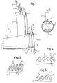
- Figure 1 shows a hair dryer 1, which consists essentially of a handle part 2 and a Blower part 3 exists.
- the handle part 2 and the blower part 3 are substantially vertical arranged to each other.
- In the blower part 3 there is an impeller and a heating coil arranged.
- the blower part 3 has a blow-out opening 19 at its front end and a suction opening 20 at its rear end.
- the handle part 2 is preferred Ergonomically designed and comfortable for a comfortable position of the hair dryer Switching elements for switching on and for setting the fan level and the heating coil on.
- a protective cover 4 is attached to the handle part 2.
- the protective cover 4 is designed as an elastic sleeve through which a power cable 5 is guided into the handle part 2.
- the task of the protective cover 4 is to avoid excessive bending or kinking of the power cable 5 in the mouth area to the handle part 2.
- a holding eyelet 7 is connected to the handle part 2 or the protective cover 4, which - as shown in FIG. 1 - serves to hang the hair dryer 1 on a hook 8.
- the blower part 3 generally has a cylindrical outer shape on which in the area the suction opening at least on two opposite surface areas first and a second support area 9, 10 are formed.
- first and a second support area 9, 10 are formed in an axis and the first contact area 9 is arranged in the region of the circumference of the blower part 3 in which the Handle part 2 merges into the blower part 3.
- the second support area 10 is in this embodiment opposite the first support area 9 in the area of the blower part 3 arranged, which is opposite to the handle part 2.
- the first and the second support area 9, 10 between the handle part 2 and the suction opening 20 arranged.
- first and the second Support area 9, 10 each formed only over part of the circumference of the blower part 3 is, as shown in section A-A of Figure 1.
- the circular arc of the support area 8, 10 preferably has a range between 10 ° and 60 °.
- the size of the Circular arc of the first and second support areas 9, 10 can, however, be individually adapted will also be up to 180 °.
- Figure 1 shows the basic shape of a first / second support area 9, 10, in cross section is designed in a simple form as a corrugated surface.
- the corrugated area is formed from elevations 15 and receiving areas 14.
- the distance between the surveys 15 is preferably chosen in such a way that the diameter of the power cable 5 can be inserted into a receiving area 14 and slipping of the inserted power cable 5 from a receiving area 14 into an adjacent receiving area 14 is prevented.
- first and the second support area 9, 10 is also in the manner possible that the first and the second support area 9, 10 adjoin one another and preferably Receiving areas 14 are formed in the form of an orbiting spiral.
- Figure 2 shows a further advantageous embodiment of the invention, in which the first Support area 9 is formed on the protective cover 4.
- the protective cover is preferably 4th made of an elastic material and can be bent in such a way that the first contact area 9 is arranged approximately parallel to the second contact area 10 is.
- the second support area 10 is opposite on the blower part 3 arranged to handle part 2.
- the embodiment of Figure 2 offers the Advantage that by bending the protective cover 4 back towards the suction opening 20 and winding the power cable 5 on the first and second Support area 9, 10 due to the elasticity of the protective cover 4 a bias in the wound loops of the power cable 5 is generated with which the power cable 5 with a pretensioning force is pressed onto the first or the second support area 9, 10. This makes it difficult for the power cable 5 to slip or shift.
- FIG. 2 shows in detail a further advantageous embodiment in which a Receiving area 14 of the first support area 9 is designed as a clamping element.
- the clamping element is delimited by a first and a second web 12, 13.
- the first and the second web 12, 13 are elastic and have a height that is preferably is over half the diameter of the power cable 5.
- the first and the second web 12, 13 is shaped in the direction of the center of the receiving area 14, so that the receiving area 14 has an opening upwards which is narrower than the distance between the first and the second web 12, 13. In this way, falling out of the power cable 5 prevented.
- the receiving area 14 has Cross-section on a pitch circle shape that is greater than 180 °.
- the embodiment of the receiving area shown in the detailed view is preferred 14 as the last receiving area 14 on the edge of the first contact area on the Protective cover 4 is formed and is used to hold the end piece of the power cable 5 which the plug 6 is formed. By clamping it is also possible to have one exert increased voltage on the power cable 5 so that the power cable 5 safely held and wound between the first and the second support area 9, 10 remains.
- the design of the receiving area 14 corresponds to the detailed view in FIG. 2 also in other embodiments, e.g. the first contact area 9 in FIG. 1 possible.
- the clamping element shown in the detailed view of FIG. 2 can also be opened the second support area 10 on the blower part 3.
- FIG. 3 shows a simple embodiment of a first and / or second contact area 9, 10, which consists essentially of webs 16 and intermediate receiving areas 14 is constructed.
- the webs 16 are preferably made of an elastic material formed and the distance between the webs 16 from one another is selected in such a way that a power cable 5 inserted into the receiving area 14 is laterally clamped by the webs 16 is.
- the webs 16 are preferably at least as high as half the diameter of the power cable 5, whereby a secure hold in the area of the power cable 5 is made possible.
- two webs 16 are at least one receiving area 14 inclined towards the receiving area 14, so that a clamping accordingly the detailed view of Figure 2 is achieved. In this way it will also fall out of the power cable 5 prevented from the receiving area 14.
- FIG. 4 shows a further embodiment of a first or second contact area 9, 10, in which receiving areas 14 are provided, which are rounded off by rounded webs 17 are spaced.
- the receiving areas 14 preferably also have a rounded shape on, which is adapted to the round shape of the power cable 5.
- a clamping element 11 is provided, which has a receiving area 14 and a first and second web 12, 13.
- the embodiments of the first and second support area 9, 10 correspond to the Figures 3 and 4 can either, as shown in Figure 1, on the blower part 3 or as shown in Figure 2, are formed on the blower part 3 and on the protective cover 4.
- the first support area 9 on the Arrange protective cover 4 in such a way that the protective cover 4 contrary to the embodiment 2 not to the rear, but to the front in the direction of the blow-out opening is bent.
- the second support area 10 is also in the area the blow-out opening 19 arranged on the blower part 3.
- first and the second support area 9, 10 are arranged in the area of the suction opening of the blower part 3
- the first and second support areas 9, 10 also in the area of the blow-out opening on the blower part 3 can be arranged.
- the first and the second support areas 9, 10 are preferably made of one material or have a corresponding surface that has an increased coefficient of friction, preferably has an increased coefficient of static and / or sliding friction. This offers the advantage that the parts of the power cable that are on the first or second support area 9, 10 rest, against slipping and being pulled out by the raised Coefficients of friction are secured.
- the first and the second support area are 9, 10 made of the same material as the component on which they are arranged.
- the first or the second support area 9, 10 made of the same material like the blower part 3 or the protective cover 4 formed. This enables a special inexpensive manufacturing.
- the receiving areas 14 preferably have an at least partially circular curvature on whose radius is adapted to the radius of the power cable 5 in such a way that the power cable 5 can be placed snugly in the receiving area 14.
- the clamping element 11 can also be replaced by two inwardly inclined webs a correspondingly high web is shown that leads to the recording area 14 is inclined and in this way an inserted in the receiving area 14 Power cable 5 holds in the receiving area 14 against falling out or pulling out.
- FIG. 5 shows a clamping element 11 which is only raised in the direction of the receiving area 14 inclined web 21 which cooperates with an elevation 15 and the clamping element 11 forms.
- a holding force is exerted laterally by prestressing the raised web 21.
Landscapes
- Cleaning And Drying Hair (AREA)
- Suspension Of Electric Lines Or Cables (AREA)
Abstract
Description
- Fig.1
- einen Haartrockner,
- Fig.2
- einen Haartrockner mit einer Schutzhülle, die einen Auflagebereich aufweist,
- Fig.3
- eine bevorzugte Ausführungsform eines Auflagebereiches,
- Fig.4
- eine weitere bevorzugte Ausführungsform eines Auflagereichs, und
- Fig.5
- ein Klemmelement mit einem erhöhten Steg.
Am Griffteil 2, vorzugsweise im Bereich der Schutzhülle 4, ist eine Halteöse 7 mit dem Griffteil 2 oder der Schutzhülle 4 verbunden, die - wie in Figur 1 dargestellt - zum Aufhängen des Haartrockners 1 an einem Haken 8 dient.
- 1
- Haartrockner
- 2
- Griffteil
- 3
- Gebläseteil
- 4
- Schutzhülle
- 5
- Stromkabel
- 6
- Stecker
- 7
- Halteöse
- 8
- Haken
- 9
- erster Auflagebereich
- 10
- zweiter Auflagebereich
- 11
- Klemmelement
- 12
- erster Steg
- 13
- zweiter Steg
- 14
- Aufnahmebereich
- 15
- Erhebung
- 16
- Steg
- 19
- Ausblasöffnung
- 20
- Ansaugöffnung
- 21
- ernöhter Steg
Claims (9)
- Haartrockner mit einem Gehäuse und mit einem Stromkabel zum Anschließen des Haartrockners an eine Stromversorgung, dadurch gekennzeichnet, daß der Haartrockner einen ersten und zweiten Auflagebereich (9,10) aufweist, daß der erste und zweite Auflagebereich (9,10) nahezu auf einer Achse gegenüberliegend angeordnet sind, und daß der erste und/oder der zweite Auflagebereich (9,10) Halteelemente (14,15,16,21) aufweist, die ein geordnetes Aufwickeln des Stromkabels (5) in Form von Schleifen auf dem ersten und zweiten Auflagebereich (9,10) unterstützen.
- Haartrockner nach Anspruch 1, dadurch gekennzeichnet, daß der Haartrockner ein Griffteil (2) und ein Gebläseteil (3) aufweist, daß am Griffteil (2) eine Schutzhülle (4) angebracht ist, daß durch die Schutzhülle (4) das Stromkabel (5) in das Griffteil (3) geführt ist, daß die Schutzhülle (4) einen ersten Auflagebereich (9) aufweist, und daß der zweite Auflagebereich (10) auf dem Gebläseteil (3) ausgebildet ist.
- Haartrockner nach Anspruch 2, dadurch gekennzeichnet, daß die Schutzhülle (4) elastisch ausgebildet ist und in einen vorgebbaren Winkel zur Achse des Griffteils biegbar ist.
- Haartrockner nach einem der Ansprüche 1 bis 3, dadurch gekennzeichnet, daß die Halteelemente in Form von nebeneinander angeordneten länglichen Vertiefungen (14) ausgebildet sind.
- Haartrockner nach Anspruch 4, dadurch gekennzeichnet, daß eine Vertiefung (14) einen Querschnitt aufweist, der an den Querschnitt des Stromkabels (5) in der Weise angepaßt ist, daß mindestens ein Teil des Stromkabels (5) in die Vertiefung (14) eingelegt werden kann.
- Haartrockner nach einem der Ansprüche 1 bis 5, dadurch gekennzeichnet, daß ein Auflagebereich (9, 10) ein Klemmelement (11) aufweist, daß das Klemmelement (11) in der Weise ausgebildet ist, daß ein in das Klemmelement (11) eingelegtes Stromkabel (5) vom Klemmelement (11) festgehalten wird.
- Haartrockner nach Anspruch 6, dadurch gekennzeichnet, daß das Klemmelement (11) in Form von nebeneinander angeordneten Stegen (16) ausgebildet ist, und daß die Stege (16) höher als der halbe Durchmesser des Stromkabels (5) sind.
- Haartrockner nach Anspruch 7, dadurch gekennzeichnet, daß die Stege (16) im oberen Endbereich zueinander ausgerichtet sind.
- Haartrockner nach einem der Ansprüche 1 bis 8, dadurch gekennzeichnet, daß der erste und/oder der zweite Auflagebereich (9, 10) eine Oberfläche mit erhöhtem Reibungskoeffizienten aufweisen.
Applications Claiming Priority (2)
| Application Number | Priority Date | Filing Date | Title |
|---|---|---|---|
| DE10021314 | 2000-05-02 | ||
| DE10021314A DE10021314B4 (de) | 2000-05-02 | 2000-05-02 | Haartrockner mit einer Aufwickelvorrichtung für ein Stromkabel |
Publications (3)
| Publication Number | Publication Date |
|---|---|
| EP1151690A2 true EP1151690A2 (de) | 2001-11-07 |
| EP1151690A3 EP1151690A3 (de) | 2003-09-24 |
| EP1151690B1 EP1151690B1 (de) | 2009-06-24 |
Family
ID=7640507
Family Applications (1)
| Application Number | Title | Priority Date | Filing Date |
|---|---|---|---|
| EP01110264A Expired - Lifetime EP1151690B1 (de) | 2000-05-02 | 2001-04-25 | Haartrockner mit einer Aufwickelvorrichtung für ein Stromkabel |
Country Status (4)
| Country | Link |
|---|---|
| EP (1) | EP1151690B1 (de) |
| AT (1) | ATE434394T1 (de) |
| DE (2) | DE10021314B4 (de) |
| ES (1) | ES2327603T3 (de) |
Cited By (3)
| Publication number | Priority date | Publication date | Assignee | Title |
|---|---|---|---|---|
| CN107692472A (zh) * | 2017-05-22 | 2018-02-16 | 梧州理想科技有限公司 | 一种新型吹风机装置 |
| CN108283355A (zh) * | 2017-05-22 | 2018-07-17 | 梧州理想科技有限公司 | 一种改进型吹风机装置 |
| EP4449941A1 (de) | 2023-04-20 | 2024-10-23 | Babyliss Faco SRL | Haartrockner mit schnuraufbewahrungsvorrichtung |
Families Citing this family (2)
| Publication number | Priority date | Publication date | Assignee | Title |
|---|---|---|---|---|
| DE102008035980A1 (de) * | 2008-08-01 | 2010-02-04 | BSH Bosch und Siemens Hausgeräte GmbH | Elektrisch betreibbares Kleingerät mit Haltevorrichtung |
| DE202011103104U1 (de) * | 2011-07-12 | 2012-07-20 | Nilfisk-Advance A/S | Klemmvorrichtung für eine elektrische Zuleitung für ein Reinigungsgerät |
Family Cites Families (8)
| Publication number | Priority date | Publication date | Assignee | Title |
|---|---|---|---|---|
| GB2080680A (en) * | 1980-06-17 | 1982-02-10 | Fcf Ltd | Hairdryer |
| DE3501161A1 (de) * | 1985-01-16 | 1986-07-17 | Gimelli & Co. AG, Zollikofen | Von hand zu fuehrendes, elektrisches geraet |
| DE3816287A1 (de) * | 1988-05-13 | 1989-11-23 | Guenter Petz | Einfuehrungstuelle |
| DE8904382U1 (de) * | 1989-04-07 | 1989-05-24 | Schroll, Stefan, Dipl.-Ing. (FH), 8221 Nußdorf | Haarföhn mit abklappbarem Haltegriff |
| DE9114815U1 (de) * | 1991-11-28 | 1992-07-16 | Licentia Patent-Verwaltungs-Gmbh, 6000 Frankfurt | Elektrischer Handhaartrockner |
| CH688669A5 (de) * | 1993-07-22 | 1997-12-31 | Landis & Gyr Business Support | Zugentlastungsvorrichtung. |
| DE4332300C1 (de) * | 1993-09-23 | 1994-12-22 | Braun Ag | Haartrockner mit Kabelaufwickelvorrichtung |
| DE9317555U1 (de) * | 1993-11-16 | 1994-02-03 | Wu, Otto, Taipeh/T'ai-pei | Haartrockner |
-
2000
- 2000-05-02 DE DE10021314A patent/DE10021314B4/de not_active Expired - Fee Related
-
2001
- 2001-04-25 EP EP01110264A patent/EP1151690B1/de not_active Expired - Lifetime
- 2001-04-25 DE DE50114944T patent/DE50114944D1/de not_active Expired - Lifetime
- 2001-04-25 ES ES01110264T patent/ES2327603T3/es not_active Expired - Lifetime
- 2001-04-25 AT AT01110264T patent/ATE434394T1/de not_active IP Right Cessation
Cited By (4)
| Publication number | Priority date | Publication date | Assignee | Title |
|---|---|---|---|---|
| CN107692472A (zh) * | 2017-05-22 | 2018-02-16 | 梧州理想科技有限公司 | 一种新型吹风机装置 |
| CN108283355A (zh) * | 2017-05-22 | 2018-07-17 | 梧州理想科技有限公司 | 一种改进型吹风机装置 |
| EP4449941A1 (de) | 2023-04-20 | 2024-10-23 | Babyliss Faco SRL | Haartrockner mit schnuraufbewahrungsvorrichtung |
| WO2024217712A1 (fr) | 2023-04-20 | 2024-10-24 | Babyliss FACO SRL | Seche-cheveux avec dispositif de rangement de cordon |
Also Published As
| Publication number | Publication date |
|---|---|
| ATE434394T1 (de) | 2009-07-15 |
| DE10021314B4 (de) | 2006-02-09 |
| EP1151690B1 (de) | 2009-06-24 |
| DE10021314A1 (de) | 2001-11-15 |
| EP1151690A3 (de) | 2003-09-24 |
| DE50114944D1 (de) | 2009-08-06 |
| ES2327603T3 (es) | 2009-11-02 |
Similar Documents
| Publication | Publication Date | Title |
|---|---|---|
| DE3430402C2 (de) | ||
| DE4036834A1 (de) | Bindevorrichtung fuer netzanschlussschnuere | |
| EP0702181B1 (de) | Rohr- und Kabelschelle mit Fussteil und Aufnahmebügel | |
| EP1151690B1 (de) | Haartrockner mit einer Aufwickelvorrichtung für ein Stromkabel | |
| DE1912219B2 (de) | Aus schraubenfoermig vorgeformten draehten bestehendes halteelement zum befestigen von elektrischen leitungen auf isolatoren | |
| DE2706326C2 (de) | Steckverbindung für ein Tauchthermoelement | |
| US4265362A (en) | Device for releasably holding relatively slim articles | |
| DE2923893A1 (de) | Haengeklemme fuer isolierte leiter und leiterbuendel | |
| EP0434008B1 (de) | Schutzvorrichtung für Injektionsnadeln | |
| DE19816784A1 (de) | Bolzenhaltevorrichtung | |
| WO1999046840A1 (de) | Steckernetzgerät | |
| EP0072030B1 (de) | Halterung für einen Pfeifenreiniger | |
| EP0655300A1 (de) | Vorrichtung zur Befestigung eines Rohres in einem Hülsenteil | |
| EP0778436B1 (de) | Tülle-Halter-Vorrichtung | |
| DE3837340C1 (de) | ||
| DE2853463A1 (de) | Elektrische mehrfach-steckdose mit schutzkontakten | |
| DE2924518C2 (de) | Steckverbindungsvorrichtung für Schmuckstücke | |
| EP2320777B1 (de) | Elektrisch betreibbares kleingerät mit haltevorrichtung | |
| EP0954078A1 (de) | Halteeinrichtung für wenigstens ein Kabel oder eine Leitung | |
| DE820190C (de) | Lockenwickler | |
| DE202024104797U1 (de) | Halterungsvorrichtung für einen Hammer | |
| DE9216445U1 (de) | Vorrichtung zum Halten eines Schirmes in Kraftfahrzeugen | |
| DE1615584C (de) | Elektrischer Stecker | |
| DE20215285U1 (de) | Wickelansatz für das Kabel eines Akkuladegerätes | |
| DE102021130256A1 (de) | Protektor |
Legal Events
| Date | Code | Title | Description |
|---|---|---|---|
| PUAI | Public reference made under article 153(3) epc to a published international application that has entered the european phase |
Free format text: ORIGINAL CODE: 0009012 |
|
| AK | Designated contracting states |
Kind code of ref document: A2 Designated state(s): AT BE CH CY DE DK ES FI FR GB GR IE IT LI LU MC NL PT SE TR |
|
| AX | Request for extension of the european patent |
Free format text: AL;LT;LV;MK;RO;SI |
|
| PUAL | Search report despatched |
Free format text: ORIGINAL CODE: 0009013 |
|
| AK | Designated contracting states |
Kind code of ref document: A3 Designated state(s): AT BE CH CY DE DK ES FI FR GB GR IE IT LI LU MC NL PT SE TR |
|
| AX | Request for extension of the european patent |
Extension state: AL LT LV MK RO SI |
|
| RAP1 | Party data changed (applicant data changed or rights of an application transferred) |
Owner name: BSH BOSCH UND SIEMENS HAUSGERAETE GMBH |
|
| 17P | Request for examination filed |
Effective date: 20040324 |
|
| AKX | Designation fees paid |
Designated state(s): AT BE CH CY DE DK ES FI FR GB GR IE IT LI LU MC NL PT SE TR |
|
| GRAP | Despatch of communication of intention to grant a patent |
Free format text: ORIGINAL CODE: EPIDOSNIGR1 |
|
| GRAS | Grant fee paid |
Free format text: ORIGINAL CODE: EPIDOSNIGR3 |
|
| GRAA | (expected) grant |
Free format text: ORIGINAL CODE: 0009210 |
|
| AK | Designated contracting states |
Kind code of ref document: B1 Designated state(s): AT BE CH CY DE DK ES FI FR GB GR IE IT LI LU MC NL PT SE TR |
|
| REG | Reference to a national code |
Ref country code: GB Ref legal event code: FG4D Free format text: NOT ENGLISH |
|
| REG | Reference to a national code |
Ref country code: CH Ref legal event code: EP |
|
| REG | Reference to a national code |
Ref country code: IE Ref legal event code: FG4D Free format text: LANGUAGE OF EP DOCUMENT: GERMAN |
|
| REF | Corresponds to: |
Ref document number: 50114944 Country of ref document: DE Date of ref document: 20090806 Kind code of ref document: P |
|
| PG25 | Lapsed in a contracting state [announced via postgrant information from national office to epo] |
Ref country code: FI Free format text: LAPSE BECAUSE OF FAILURE TO SUBMIT A TRANSLATION OF THE DESCRIPTION OR TO PAY THE FEE WITHIN THE PRESCRIBED TIME-LIMIT Effective date: 20090624 |
|
| REG | Reference to a national code |
Ref country code: ES Ref legal event code: FG2A Ref document number: 2327603 Country of ref document: ES Kind code of ref document: T3 |
|
| PG25 | Lapsed in a contracting state [announced via postgrant information from national office to epo] |
Ref country code: SE Free format text: LAPSE BECAUSE OF FAILURE TO SUBMIT A TRANSLATION OF THE DESCRIPTION OR TO PAY THE FEE WITHIN THE PRESCRIBED TIME-LIMIT Effective date: 20090924 |
|
| NLV1 | Nl: lapsed or annulled due to failure to fulfill the requirements of art. 29p and 29m of the patents act | ||
| REG | Reference to a national code |
Ref country code: IE Ref legal event code: FD4D |
|
| PG25 | Lapsed in a contracting state [announced via postgrant information from national office to epo] |
Ref country code: NL Free format text: LAPSE BECAUSE OF FAILURE TO SUBMIT A TRANSLATION OF THE DESCRIPTION OR TO PAY THE FEE WITHIN THE PRESCRIBED TIME-LIMIT Effective date: 20090624 |
|
| PG25 | Lapsed in a contracting state [announced via postgrant information from national office to epo] |
Ref country code: PT Free format text: LAPSE BECAUSE OF FAILURE TO SUBMIT A TRANSLATION OF THE DESCRIPTION OR TO PAY THE FEE WITHIN THE PRESCRIBED TIME-LIMIT Effective date: 20091024 |
|
| PG25 | Lapsed in a contracting state [announced via postgrant information from national office to epo] |
Ref country code: DK Free format text: LAPSE BECAUSE OF FAILURE TO SUBMIT A TRANSLATION OF THE DESCRIPTION OR TO PAY THE FEE WITHIN THE PRESCRIBED TIME-LIMIT Effective date: 20090624 Ref country code: IE Free format text: LAPSE BECAUSE OF FAILURE TO SUBMIT A TRANSLATION OF THE DESCRIPTION OR TO PAY THE FEE WITHIN THE PRESCRIBED TIME-LIMIT Effective date: 20090624 |
|
| PLBE | No opposition filed within time limit |
Free format text: ORIGINAL CODE: 0009261 |
|
| STAA | Information on the status of an ep patent application or granted ep patent |
Free format text: STATUS: NO OPPOSITION FILED WITHIN TIME LIMIT |
|
| 26N | No opposition filed |
Effective date: 20100325 |
|
| PG25 | Lapsed in a contracting state [announced via postgrant information from national office to epo] |
Ref country code: GR Free format text: LAPSE BECAUSE OF FAILURE TO SUBMIT A TRANSLATION OF THE DESCRIPTION OR TO PAY THE FEE WITHIN THE PRESCRIBED TIME-LIMIT Effective date: 20090925 |
|
| BERE | Be: lapsed |
Owner name: BSH BOSCH UND SIEMENS HAUSGERATE G.M.B.H. Effective date: 20100430 |
|
| PG25 | Lapsed in a contracting state [announced via postgrant information from national office to epo] |
Ref country code: MC Free format text: LAPSE BECAUSE OF NON-PAYMENT OF DUE FEES Effective date: 20100430 |
|
| REG | Reference to a national code |
Ref country code: CH Ref legal event code: PL |
|
| PG25 | Lapsed in a contracting state [announced via postgrant information from national office to epo] |
Ref country code: CH Free format text: LAPSE BECAUSE OF NON-PAYMENT OF DUE FEES Effective date: 20100430 Ref country code: LI Free format text: LAPSE BECAUSE OF NON-PAYMENT OF DUE FEES Effective date: 20100430 |
|
| PG25 | Lapsed in a contracting state [announced via postgrant information from national office to epo] |
Ref country code: BE Free format text: LAPSE BECAUSE OF NON-PAYMENT OF DUE FEES Effective date: 20100430 |
|
| PG25 | Lapsed in a contracting state [announced via postgrant information from national office to epo] |
Ref country code: AT Free format text: LAPSE BECAUSE OF NON-PAYMENT OF DUE FEES Effective date: 20100425 |
|
| PG25 | Lapsed in a contracting state [announced via postgrant information from national office to epo] |
Ref country code: CY Free format text: LAPSE BECAUSE OF FAILURE TO SUBMIT A TRANSLATION OF THE DESCRIPTION OR TO PAY THE FEE WITHIN THE PRESCRIBED TIME-LIMIT Effective date: 20090624 |
|
| PG25 | Lapsed in a contracting state [announced via postgrant information from national office to epo] |
Ref country code: LU Free format text: LAPSE BECAUSE OF NON-PAYMENT OF DUE FEES Effective date: 20100425 |
|
| PG25 | Lapsed in a contracting state [announced via postgrant information from national office to epo] |
Ref country code: TR Free format text: LAPSE BECAUSE OF FAILURE TO SUBMIT A TRANSLATION OF THE DESCRIPTION OR TO PAY THE FEE WITHIN THE PRESCRIBED TIME-LIMIT Effective date: 20090624 |
|
| REG | Reference to a national code |
Ref country code: FR Ref legal event code: PLFP Year of fee payment: 15 |
|
| REG | Reference to a national code |
Ref country code: DE Ref legal event code: R081 Ref document number: 50114944 Country of ref document: DE Owner name: BSH HAUSGERAETE GMBH, DE Free format text: FORMER OWNER: BSH BOSCH UND SIEMENS HAUSGERAETE GMBH, 81739 MUENCHEN, DE Effective date: 20150402 |
|
| REG | Reference to a national code |
Ref country code: ES Ref legal event code: PC2A Owner name: BSH HAUSGERATE GMBH Effective date: 20150527 |
|
| REG | Reference to a national code |
Ref country code: FR Ref legal event code: CD Owner name: BSH HAUSGERATE GMBH Effective date: 20151022 |
|
| REG | Reference to a national code |
Ref country code: FR Ref legal event code: PLFP Year of fee payment: 16 |
|
| REG | Reference to a national code |
Ref country code: FR Ref legal event code: PLFP Year of fee payment: 17 |
|
| PGFP | Annual fee paid to national office [announced via postgrant information from national office to epo] |
Ref country code: FR Payment date: 20170424 Year of fee payment: 17 Ref country code: DE Payment date: 20170430 Year of fee payment: 17 Ref country code: GB Payment date: 20170425 Year of fee payment: 17 |
|
| PGFP | Annual fee paid to national office [announced via postgrant information from national office to epo] |
Ref country code: ES Payment date: 20170503 Year of fee payment: 17 Ref country code: IT Payment date: 20170420 Year of fee payment: 17 |
|
| REG | Reference to a national code |
Ref country code: DE Ref legal event code: R119 Ref document number: 50114944 Country of ref document: DE |
|
| GBPC | Gb: european patent ceased through non-payment of renewal fee |
Effective date: 20180425 |
|
| PG25 | Lapsed in a contracting state [announced via postgrant information from national office to epo] |
Ref country code: DE Free format text: LAPSE BECAUSE OF NON-PAYMENT OF DUE FEES Effective date: 20181101 |
|
| PG25 | Lapsed in a contracting state [announced via postgrant information from national office to epo] |
Ref country code: GB Free format text: LAPSE BECAUSE OF NON-PAYMENT OF DUE FEES Effective date: 20180425 |
|
| PG25 | Lapsed in a contracting state [announced via postgrant information from national office to epo] |
Ref country code: IT Free format text: LAPSE BECAUSE OF NON-PAYMENT OF DUE FEES Effective date: 20180425 Ref country code: FR Free format text: LAPSE BECAUSE OF NON-PAYMENT OF DUE FEES Effective date: 20180430 |
|
| REG | Reference to a national code |
Ref country code: ES Ref legal event code: FD2A Effective date: 20190912 |
|
| PG25 | Lapsed in a contracting state [announced via postgrant information from national office to epo] |
Ref country code: ES Free format text: LAPSE BECAUSE OF NON-PAYMENT OF DUE FEES Effective date: 20180426 |