EP4449941A1 - Haartrockner mit schnuraufbewahrungsvorrichtung - Google Patents
Haartrockner mit schnuraufbewahrungsvorrichtung Download PDFInfo
- Publication number
- EP4449941A1 EP4449941A1 EP23168996.9A EP23168996A EP4449941A1 EP 4449941 A1 EP4449941 A1 EP 4449941A1 EP 23168996 A EP23168996 A EP 23168996A EP 4449941 A1 EP4449941 A1 EP 4449941A1
- Authority
- EP
- European Patent Office
- Prior art keywords
- handle
- hair dryer
- housing
- protective tip
- cord
- Prior art date
- Legal status (The legal status is an assumption and is not a legal conclusion. Google has not performed a legal analysis and makes no representation as to the accuracy of the status listed.)
- Withdrawn
Links
Images


Classifications
-
- A—HUMAN NECESSITIES
- A45—HAND OR TRAVELLING ARTICLES
- A45D—HAIRDRESSING OR SHAVING EQUIPMENT; EQUIPMENT FOR COSMETICS OR COSMETIC TREATMENTS, e.g. FOR MANICURING OR PEDICURING
- A45D20/00—Hair drying devices; Accessories therefor
- A45D20/04—Hot-air producers
- A45D20/08—Hot-air producers heated electrically
- A45D20/10—Hand-held drying devices, e.g. air douches
-
- A—HUMAN NECESSITIES
- A45—HAND OR TRAVELLING ARTICLES
- A45D—HAIRDRESSING OR SHAVING EQUIPMENT; EQUIPMENT FOR COSMETICS OR COSMETIC TREATMENTS, e.g. FOR MANICURING OR PEDICURING
- A45D20/00—Hair drying devices; Accessories therefor
- A45D20/04—Hot-air producers
Definitions
- the present invention relates to a hair dryer comprising a device for storing the power cable by winding it around the hair dryer.
- Hair dryers are equipped with a power cord that is usually quite long. After use, the user usually simply wraps the power cord around the hair dryer housing to store it. However, if the cord is not held by some device, it can detach and slip out of the hair dryer housing. There are therefore systems to keep the cord on the hair dryer once it is wrapped around it.
- the document CN104621947 discloses a hair dryer having a winding groove on the rear portion of its housing. The user can wind the power cord by passing it through the groove so that it is retained therein. However, since the winding is done only around the housing of the hair dryer, many loops are necessary before the cord is completely wound.
- the document DE9114815 illustrates a hair dryer that includes a cord winding device for winding the cord over the entire height of the hair dryer, namely between the hair dryer housing and the bottom of the handle.
- the distal portion of the handle includes a hollow-shaped receiving recess for passing the cable therethrough
- the hair dryer housing includes a protrusion to center the cable and prevent it from slipping off the housing.
- the document EP1151690A2 discloses a hair dryer comprising a device for storing the power cord compactly on the hair dryer.
- the cord is stored by winding it around two contact surfaces, corresponding on the one hand to the housing of the hair dryer and on the other hand to the cord protection sleeve located at the base of the handle of the hair dryer.
- the contact surfaces are provided with indentations into which the cord is inserted in order to be held.
- the document DE3501161 describes a hair dryer comprising a holder for winding the power cord.
- the holder is located on the lower portion of the handle, and is pivotable between a position aligned with the handle and a position perpendicular to the handle. The user can position the holder perpendicular to the handle in order to wind the cord between the holder and the housing of the hair dryer.
- the present invention aims to overcome the disadvantages of the prior art, and in particular to provide a hair dryer with efficient storage of the power cord, by winding the cord around the hair dryer.
- the invention makes it possible to hold the cord once it is placed in its storage position and to prevent it from slipping out of the housing.
- Another aim of the invention is to provide a solution which prevents damage to the cord at the outlet of the hair dryer, thanks to the presence of a movable protective tip.
- Another aim of the invention is to facilitate the handling of the hair dryer during use, thanks to the mobility of the cord protection tip at the outlet of the handle, allowing greater flexibility during movements of the cord at the outlet of the hair dryer.
- Another aim of the invention is to allow more compact storage of the hair dryer thanks to the mobility of the protective tip which is folded substantially perpendicular to the handle and avoids having additional length below the handle.
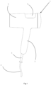
- FIG. 1 represents a side view of an exemplary hair dryer according to the invention, the protective tip of the power cord being in a position aligned with the handle of the hair dryer.
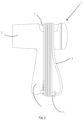
- FIG 2 represents the hair dryer of the figure 1 , with its power cord stored by winding it around the hair dryer housing and the protective tip placed approximately perpendicular to the hair dryer handle.
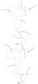
- figure 3 represents the hair dryer of the figure 1 , with the power cord protection tip placed in the intermediate position, between the alignment position with the handle and the storage position substantially perpendicular to the handle.
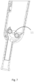
- FIG 4 represents the hair dryer of the figure 1 , with the power cord protection tip placed in a storage position approximately perpendicular to the handle.
- FIG. 5 represents a sectional view of the lower part of the handle and the protective tip, the protective tip being in a position of alignment with the handle of the hair dryer according to the invention.
- FIG. 6 represents a sectional view of the lower part of the handle and the protective tip, the protective tip being in a storage position substantially perpendicular to the handle of the hair dryer according to the invention.
- figure 7 represents the cross-section view of the figure 5 on which the power cord has not been shown, in order to illustrate the axis of rotation of the protective tip.
- FIG 8 represents a three-dimensional view of the lower portion of the handle, more specifically illustrating the handle cord exit hole.
- FIG 9 represents a partial sectional view of the figure 8 , illustrating the arrangement of the semi-spherical internal part of the protective tip in the lower part of the handle.
- the cord outlet has a shape which allows the cord to exit the handle on the same axis as that of the handle, or to exit perpendicular to the handle, following a rotation of the protective tip.
- FIG. 1 An example of a hair dryer according to the invention is illustrated in Figure 1 .
- This comprises a housing 2 fitted with a handle 3. Like all hair dryers without a battery, it is fitted with a power cord 4 exiting the hair dryer through an opening 7 located at the lower end of the handle.
- the hair dryer of the present invention comprises a device for storing the power cord after use, allowing the cord to be wound around the hair dryer. More specifically, it comprises a housing 6 formed in the upper part of the housing of the hair dryer and a movable protective tip 5 of the power cord is provided at the outlet of the hair dryer.
- the protective tip can be moved between a position of alignment with the handle, as shown in the Figure 1 , and a storage position in which the movable tip is positioned approximately perpendicular to the handle, as shown in the Figures 2 And 4 .
- each loop of the cord is placed in the housing provided for this purpose, in order to hold the cord on the housing.
- the holding housing is in fact a recess made in the housing, which preferably has a length of between 3.5 and 5.5 cm, preferably between 4 and 5 cm and a depth of between 0.7 and 1.3 cm, preferably between 0.8 and 1.2 cm.
- the size of the loops formed by the cord around the hair dryer are maximized by the device of the invention, which makes it possible to limit the number of turns to be made to store the entire cord.
- the distance traveled by the cord between the protective tip and the holding housing is preferably greater than 23 cm, more preferably greater than 24 cm. Furthermore, since the protective tip is movable, the radius of curvature of the cord at the outlet of the handle is increased, which prevents it from being damaged.
- the movable protective tip is shown in more detail on the figures 5 And 6 .
- the protective tip is located on the distal side of the handle and passes through the hole 7 located at the end of the handle.
- the tip comprises an internal part 8 to the handle and an external part 9 to the handle.
- the internal part 8 is in the form of a semi-spherical shell and is extended by the external part 9 in tubular form.
- the cord comprises a first part internal to the hair dryer which powers the electrical elements such as the motor, and a second part external to the hair dryer which allows it to be connected to the mains.
- the protective tip protects the cord as it passes outside the handle, the cord being locally housed inside the tip.
- the inner part of the tip in the form of a semi-spherical shell is preferably formed of two hollow quarter spheres fixed using two screws.
- the pillars of the two screws 10 frame the power cord to channel it inside the semi-spherical shell.
- the protective tip is movable and can pivot around an axis 11 located at the center of the semi-spherical internal part, as shown in the figure 7 .
- the semi-spherical inner part can pivot about this axis, which allows the tubular outer part to move from a position of alignment with the handle, as shown in the Figure 5 to a storage position in which the outer portion is approximately perpendicular to the handle, as shown in the Figure 6 .
- the cord in the distal part of the handle has a bending radius of at least 0.8 cm, preferably at least 1 cm, more preferably at least 1.2 cm.
- the mobility of the protective tip also allows for greater flexibility of use due to the mobility of the cord near the handle, without damaging it. The user has to be less careful during use and the cord is somewhat spared from the many movements.
- the semi-spherical portion When the protective cap is in the storage position, the semi-spherical portion is positioned so as to close the hole located at the end of the handle so that the handle remains sealed. In this position, the hole acts as a housing for the protective cap.
- the cord outlet hole has a specific shape allowing the protective tip to move from the aligned position relative to the handle to the storage position in which the tip is perpendicular to the handle. The hole is therefore located partly in the base of the handle but also partly on a lateral side of the handle so that the protective tip can pass through the handle laterally to be positioned in the storage position.
Landscapes
- Cleaning And Drying Hair (AREA)
Priority Applications (4)
| Application Number | Priority Date | Filing Date | Title |
|---|---|---|---|
| EP23168996.9A EP4449941A1 (de) | 2023-04-20 | 2023-04-20 | Haartrockner mit schnuraufbewahrungsvorrichtung |
| EP23806332.5A EP4698007A1 (de) | 2023-04-20 | 2023-11-17 | Haartrockner mit schnuraufbewahrungsvorrichtung |
| CN202380097357.3A CN120981179A (zh) | 2023-04-20 | 2023-11-17 | 具有线收纳装置的吹风机 |
| PCT/EP2023/082249 WO2024217712A1 (fr) | 2023-04-20 | 2023-11-17 | Seche-cheveux avec dispositif de rangement de cordon |
Applications Claiming Priority (1)
| Application Number | Priority Date | Filing Date | Title |
|---|---|---|---|
| EP23168996.9A EP4449941A1 (de) | 2023-04-20 | 2023-04-20 | Haartrockner mit schnuraufbewahrungsvorrichtung |
Publications (1)
| Publication Number | Publication Date |
|---|---|
| EP4449941A1 true EP4449941A1 (de) | 2024-10-23 |
Family
ID=86095924
Family Applications (2)
| Application Number | Title | Priority Date | Filing Date |
|---|---|---|---|
| EP23168996.9A Withdrawn EP4449941A1 (de) | 2023-04-20 | 2023-04-20 | Haartrockner mit schnuraufbewahrungsvorrichtung |
| EP23806332.5A Pending EP4698007A1 (de) | 2023-04-20 | 2023-11-17 | Haartrockner mit schnuraufbewahrungsvorrichtung |
Family Applications After (1)
| Application Number | Title | Priority Date | Filing Date |
|---|---|---|---|
| EP23806332.5A Pending EP4698007A1 (de) | 2023-04-20 | 2023-11-17 | Haartrockner mit schnuraufbewahrungsvorrichtung |
Country Status (3)
| Country | Link |
|---|---|
| EP (2) | EP4449941A1 (de) |
| CN (1) | CN120981179A (de) |
| WO (1) | WO2024217712A1 (de) |
Citations (7)
| Publication number | Priority date | Publication date | Assignee | Title |
|---|---|---|---|---|
| FR2482432A1 (fr) * | 1980-05-15 | 1981-11-20 | Matsushita Electric Works Ltd | Seche-cheveux |
| GB2080680A (en) * | 1980-06-17 | 1982-02-10 | Fcf Ltd | Hairdryer |
| DE3501161A1 (de) | 1985-01-16 | 1986-07-17 | Gimelli & Co. AG, Zollikofen | Von hand zu fuehrendes, elektrisches geraet |
| DE9114815U1 (de) | 1991-11-28 | 1992-07-16 | Licentia Patent-Verwaltungs-Gmbh, 6000 Frankfurt | Elektrischer Handhaartrockner |
| EP1151690A2 (de) | 2000-05-02 | 2001-11-07 | BSH Bosch und Siemens Hausgeräte GmbH | Haartrockner mit einer Aufwickelvorrichtung für ein Stromkabel |
| CN104621947A (zh) | 2013-11-15 | 2015-05-20 | 李林 | 带绕线器的电吹风 |
| CN108720234A (zh) * | 2018-06-25 | 2018-11-02 | 深圳稀树智能科技有限公司 | 吹风机 |
-
2023
- 2023-04-20 EP EP23168996.9A patent/EP4449941A1/de not_active Withdrawn
- 2023-11-17 WO PCT/EP2023/082249 patent/WO2024217712A1/fr not_active Ceased
- 2023-11-17 EP EP23806332.5A patent/EP4698007A1/de active Pending
- 2023-11-17 CN CN202380097357.3A patent/CN120981179A/zh active Pending
Patent Citations (7)
| Publication number | Priority date | Publication date | Assignee | Title |
|---|---|---|---|---|
| FR2482432A1 (fr) * | 1980-05-15 | 1981-11-20 | Matsushita Electric Works Ltd | Seche-cheveux |
| GB2080680A (en) * | 1980-06-17 | 1982-02-10 | Fcf Ltd | Hairdryer |
| DE3501161A1 (de) | 1985-01-16 | 1986-07-17 | Gimelli & Co. AG, Zollikofen | Von hand zu fuehrendes, elektrisches geraet |
| DE9114815U1 (de) | 1991-11-28 | 1992-07-16 | Licentia Patent-Verwaltungs-Gmbh, 6000 Frankfurt | Elektrischer Handhaartrockner |
| EP1151690A2 (de) | 2000-05-02 | 2001-11-07 | BSH Bosch und Siemens Hausgeräte GmbH | Haartrockner mit einer Aufwickelvorrichtung für ein Stromkabel |
| CN104621947A (zh) | 2013-11-15 | 2015-05-20 | 李林 | 带绕线器的电吹风 |
| CN108720234A (zh) * | 2018-06-25 | 2018-11-02 | 深圳稀树智能科技有限公司 | 吹风机 |
Also Published As
| Publication number | Publication date |
|---|---|
| CN120981179A (zh) | 2025-11-18 |
| EP4698007A1 (de) | 2026-02-25 |
| WO2024217712A1 (fr) | 2024-10-24 |
Similar Documents
| Publication | Publication Date | Title |
|---|---|---|
| WO2016146948A1 (fr) | Rangement pour cable electrique | |
| EP1581830A1 (de) | Spule zur aufbewahrung mit vorrichtung zum abrollen von optischen kabeln | |
| FR2721763A1 (fr) | Dispositif portatif de stockage d'une ligne téléphonique. | |
| FR2733219A1 (fr) | Dispositif de devidage de cables bobines en couronne | |
| EP4449941A1 (de) | Haartrockner mit schnuraufbewahrungsvorrichtung | |
| FR2986520A3 (fr) | Enrouleur de tuyau et agencement d'enrouleur de tuyau | |
| FR3012299A1 (fr) | Bagage roulant comportant une canne escamotable | |
| EP3515234B1 (de) | Frisiervorrichtung mit einem führungselement | |
| EP0020268A1 (de) | Faltbarer und verpackbarer Toilettartikel, z.B. Zahnbürste | |
| EP2087164A1 (de) | Bügeleisen mit verbesserter schnurführungsvorrichtung | |
| FR2767316A1 (fr) | Boite de rangement d'un cable electrique | |
| EP2993151B1 (de) | Hochleistungs-trommel | |
| FR3101785A1 (fr) | Dispositif de rangement de clubs de golf | |
| EP2888969A1 (de) | Frisiergerät mit Kabelspeicher | |
| FR2549308A1 (fr) | Enrouleur automatique de cordon electrique et de tout element analogue | |
| FR2749712A1 (fr) | Dispositif pour le montage d'au moins un cable dans un disque destine a etre positionne dans un manchon de protection d'un raccordement de cables | |
| EP1764439A1 (de) | Bügeleisen mit einer verbesserten Vorrichtung zur Kabelzuführung | |
| FR2503116A1 (fr) | Enrouleur de cables | |
| EP3974363B1 (de) | Transportvorrichtung für eine kabelrolle mit einem richtrohr | |
| EP4265551A1 (de) | Verriegelbare und abnehmbare halterung für eine trommel | |
| WO2018055271A1 (fr) | Appareil de coiffure equipe d'un capot de protection mobile | |
| FR2617819A1 (fr) | Dispositif derouleur de bobines de films en matiere plastique etirable et auto-adhesive pour fardelage de produits divers | |
| FR2636055A1 (fr) | Derouleur pour tube plastique semi-rigide | |
| FR3165591A3 (fr) | Dispositif de bobinage pour la gestion d’un élément flexible dans un environnement de travail | |
| WO2021198986A1 (fr) | Ensemble collier-laisse a enrouleur integre |
Legal Events
| Date | Code | Title | Description |
|---|---|---|---|
| PUAI | Public reference made under article 153(3) epc to a published international application that has entered the european phase |
Free format text: ORIGINAL CODE: 0009012 |
|
| STAA | Information on the status of an ep patent application or granted ep patent |
Free format text: STATUS: THE APPLICATION HAS BEEN PUBLISHED |
|
| AK | Designated contracting states |
Kind code of ref document: A1 Designated state(s): AL AT BE BG CH CY CZ DE DK EE ES FI FR GB GR HR HU IE IS IT LI LT LU LV MC ME MK MT NL NO PL PT RO RS SE SI SK SM TR |
|
| STAA | Information on the status of an ep patent application or granted ep patent |
Free format text: STATUS: THE APPLICATION IS DEEMED TO BE WITHDRAWN |
|
| 18D | Application deemed to be withdrawn |
Effective date: 20250424 |