EP4449941A1 - Hair dryer with cord storage device - Google Patents
Hair dryer with cord storage device Download PDFInfo
- Publication number
- EP4449941A1 EP4449941A1 EP23168996.9A EP23168996A EP4449941A1 EP 4449941 A1 EP4449941 A1 EP 4449941A1 EP 23168996 A EP23168996 A EP 23168996A EP 4449941 A1 EP4449941 A1 EP 4449941A1
- Authority
- EP
- European Patent Office
- Prior art keywords
- handle
- hair dryer
- housing
- protective tip
- cord
- Prior art date
- Legal status (The legal status is an assumption and is not a legal conclusion. Google has not performed a legal analysis and makes no representation as to the accuracy of the status listed.)
- Withdrawn
Links
Images


Classifications
-
- A—HUMAN NECESSITIES
- A45—HAND OR TRAVELLING ARTICLES
- A45D—HAIRDRESSING OR SHAVING EQUIPMENT; EQUIPMENT FOR COSMETICS OR COSMETIC TREATMENTS, e.g. FOR MANICURING OR PEDICURING
- A45D20/00—Hair drying devices; Accessories therefor
- A45D20/04—Hot-air producers
- A45D20/08—Hot-air producers heated electrically
- A45D20/10—Hand-held drying devices, e.g. air douches
-
- A—HUMAN NECESSITIES
- A45—HAND OR TRAVELLING ARTICLES
- A45D—HAIRDRESSING OR SHAVING EQUIPMENT; EQUIPMENT FOR COSMETICS OR COSMETIC TREATMENTS, e.g. FOR MANICURING OR PEDICURING
- A45D20/00—Hair drying devices; Accessories therefor
- A45D20/04—Hot-air producers
Definitions
- the present invention relates to a hair dryer comprising a device for storing the power cable by winding it around the hair dryer.
- Hair dryers are equipped with a power cord that is usually quite long. After use, the user usually simply wraps the power cord around the hair dryer housing to store it. However, if the cord is not held by some device, it can detach and slip out of the hair dryer housing. There are therefore systems to keep the cord on the hair dryer once it is wrapped around it.
- the document CN104621947 discloses a hair dryer having a winding groove on the rear portion of its housing. The user can wind the power cord by passing it through the groove so that it is retained therein. However, since the winding is done only around the housing of the hair dryer, many loops are necessary before the cord is completely wound.
- the document DE9114815 illustrates a hair dryer that includes a cord winding device for winding the cord over the entire height of the hair dryer, namely between the hair dryer housing and the bottom of the handle.
- the distal portion of the handle includes a hollow-shaped receiving recess for passing the cable therethrough
- the hair dryer housing includes a protrusion to center the cable and prevent it from slipping off the housing.
- the document EP1151690A2 discloses a hair dryer comprising a device for storing the power cord compactly on the hair dryer.
- the cord is stored by winding it around two contact surfaces, corresponding on the one hand to the housing of the hair dryer and on the other hand to the cord protection sleeve located at the base of the handle of the hair dryer.
- the contact surfaces are provided with indentations into which the cord is inserted in order to be held.
- the document DE3501161 describes a hair dryer comprising a holder for winding the power cord.
- the holder is located on the lower portion of the handle, and is pivotable between a position aligned with the handle and a position perpendicular to the handle. The user can position the holder perpendicular to the handle in order to wind the cord between the holder and the housing of the hair dryer.
- the present invention aims to overcome the disadvantages of the prior art, and in particular to provide a hair dryer with efficient storage of the power cord, by winding the cord around the hair dryer.
- the invention makes it possible to hold the cord once it is placed in its storage position and to prevent it from slipping out of the housing.
- Another aim of the invention is to provide a solution which prevents damage to the cord at the outlet of the hair dryer, thanks to the presence of a movable protective tip.
- Another aim of the invention is to facilitate the handling of the hair dryer during use, thanks to the mobility of the cord protection tip at the outlet of the handle, allowing greater flexibility during movements of the cord at the outlet of the hair dryer.
- Another aim of the invention is to allow more compact storage of the hair dryer thanks to the mobility of the protective tip which is folded substantially perpendicular to the handle and avoids having additional length below the handle.
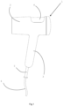
- FIG. 1 represents a side view of an exemplary hair dryer according to the invention, the protective tip of the power cord being in a position aligned with the handle of the hair dryer.
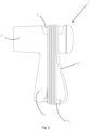
- FIG 2 represents the hair dryer of the figure 1 , with its power cord stored by winding it around the hair dryer housing and the protective tip placed approximately perpendicular to the hair dryer handle.
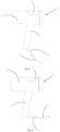
- figure 3 represents the hair dryer of the figure 1 , with the power cord protection tip placed in the intermediate position, between the alignment position with the handle and the storage position substantially perpendicular to the handle.
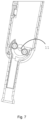
- FIG 4 represents the hair dryer of the figure 1 , with the power cord protection tip placed in a storage position approximately perpendicular to the handle.
- FIG. 5 represents a sectional view of the lower part of the handle and the protective tip, the protective tip being in a position of alignment with the handle of the hair dryer according to the invention.
- FIG. 6 represents a sectional view of the lower part of the handle and the protective tip, the protective tip being in a storage position substantially perpendicular to the handle of the hair dryer according to the invention.
- figure 7 represents the cross-section view of the figure 5 on which the power cord has not been shown, in order to illustrate the axis of rotation of the protective tip.
- FIG 8 represents a three-dimensional view of the lower portion of the handle, more specifically illustrating the handle cord exit hole.
- FIG 9 represents a partial sectional view of the figure 8 , illustrating the arrangement of the semi-spherical internal part of the protective tip in the lower part of the handle.
- the cord outlet has a shape which allows the cord to exit the handle on the same axis as that of the handle, or to exit perpendicular to the handle, following a rotation of the protective tip.
- FIG. 1 An example of a hair dryer according to the invention is illustrated in Figure 1 .
- This comprises a housing 2 fitted with a handle 3. Like all hair dryers without a battery, it is fitted with a power cord 4 exiting the hair dryer through an opening 7 located at the lower end of the handle.
- the hair dryer of the present invention comprises a device for storing the power cord after use, allowing the cord to be wound around the hair dryer. More specifically, it comprises a housing 6 formed in the upper part of the housing of the hair dryer and a movable protective tip 5 of the power cord is provided at the outlet of the hair dryer.
- the protective tip can be moved between a position of alignment with the handle, as shown in the Figure 1 , and a storage position in which the movable tip is positioned approximately perpendicular to the handle, as shown in the Figures 2 And 4 .
- each loop of the cord is placed in the housing provided for this purpose, in order to hold the cord on the housing.
- the holding housing is in fact a recess made in the housing, which preferably has a length of between 3.5 and 5.5 cm, preferably between 4 and 5 cm and a depth of between 0.7 and 1.3 cm, preferably between 0.8 and 1.2 cm.
- the size of the loops formed by the cord around the hair dryer are maximized by the device of the invention, which makes it possible to limit the number of turns to be made to store the entire cord.
- the distance traveled by the cord between the protective tip and the holding housing is preferably greater than 23 cm, more preferably greater than 24 cm. Furthermore, since the protective tip is movable, the radius of curvature of the cord at the outlet of the handle is increased, which prevents it from being damaged.
- the movable protective tip is shown in more detail on the figures 5 And 6 .
- the protective tip is located on the distal side of the handle and passes through the hole 7 located at the end of the handle.
- the tip comprises an internal part 8 to the handle and an external part 9 to the handle.
- the internal part 8 is in the form of a semi-spherical shell and is extended by the external part 9 in tubular form.
- the cord comprises a first part internal to the hair dryer which powers the electrical elements such as the motor, and a second part external to the hair dryer which allows it to be connected to the mains.
- the protective tip protects the cord as it passes outside the handle, the cord being locally housed inside the tip.
- the inner part of the tip in the form of a semi-spherical shell is preferably formed of two hollow quarter spheres fixed using two screws.
- the pillars of the two screws 10 frame the power cord to channel it inside the semi-spherical shell.
- the protective tip is movable and can pivot around an axis 11 located at the center of the semi-spherical internal part, as shown in the figure 7 .
- the semi-spherical inner part can pivot about this axis, which allows the tubular outer part to move from a position of alignment with the handle, as shown in the Figure 5 to a storage position in which the outer portion is approximately perpendicular to the handle, as shown in the Figure 6 .
- the cord in the distal part of the handle has a bending radius of at least 0.8 cm, preferably at least 1 cm, more preferably at least 1.2 cm.
- the mobility of the protective tip also allows for greater flexibility of use due to the mobility of the cord near the handle, without damaging it. The user has to be less careful during use and the cord is somewhat spared from the many movements.
- the semi-spherical portion When the protective cap is in the storage position, the semi-spherical portion is positioned so as to close the hole located at the end of the handle so that the handle remains sealed. In this position, the hole acts as a housing for the protective cap.
- the cord outlet hole has a specific shape allowing the protective tip to move from the aligned position relative to the handle to the storage position in which the tip is perpendicular to the handle. The hole is therefore located partly in the base of the handle but also partly on a lateral side of the handle so that the protective tip can pass through the handle laterally to be positioned in the storage position.
Landscapes
- Cleaning And Drying Hair (AREA)
Abstract
La présente invention divulgue un sèche-cheveux comportant :
- un boitier avec une bouche d'entrée d'air et une bouche de sortie d'air;
- une poignée ;
- un cordon d'alimentation électrique ;
- un embout de protection du cordon d'alimentation électrique traversant un orifice compris dans la partie distale de la poignée ;
- un logement de maintien du câble situé dans la partie supérieure du boitier du sèche-cheveux ;
caractérisé en ce que l'embout de protection est mobile entre une position d'alignement avec la poignée et une position de rangement du cordon d'alimentation électrique dans lequel l'embout de protection est approximativement perpendiculaire à la poignée, ledit cordon d'alimentation électrique étant rangé, en utilisation, par enroulement à l'aide du logement de maintien du câble prévu dans le boitier et de l'embout de protection.

- a box with an air inlet and an air outlet;
- a handle;
- an electrical power cord;
- a protective tip for the electrical power cord passing through an orifice included in the distal part of the handle;
- a cable retention housing located in the upper part of the hair dryer housing;
characterized in that the protective tip is movable between a position of alignment with the handle and a position for storing the electrical power cord in which the protective tip is approximately perpendicular to the handle, said electrical power cord being stored, in use, by winding using the cable holding housing provided in the housing and the protective tip.
Description
La présente invention se rapporte à un sèche-cheveux comprenant un dispositif pour ranger le câble d'alimentation par enroulement de celui-ci autour du sèche-cheveux.The present invention relates to a hair dryer comprising a device for storing the power cable by winding it around the hair dryer.
Les sèche-cheveux sont équipés d'un câble d'alimentation électrique généralement assez long. Après utilisation, l'utilisateur enroule généralement le cordon d'alimentation simplement autour du boitier du sèche-cheveux pour le ranger. Cependant, si le câble n'est pas maintenu par un quelconque dispositif, il peut se détacher et glisser du boîtier du sèche-cheveux. Il existe donc des systèmes permettant de maintenir le cordon sur le sèche-cheveux une fois qu'il est enroulé autour de celui-ci.Hair dryers are equipped with a power cord that is usually quite long. After use, the user usually simply wraps the power cord around the hair dryer housing to store it. However, if the cord is not held by some device, it can detach and slip out of the hair dryer housing. There are therefore systems to keep the cord on the hair dryer once it is wrapped around it.
Le document
Le document
Le document
Le document
Lorsque le câble est enroulé autour du sèche-cheveux, son rayon de courbure à la sortie de la poignée est très petit. Cette pliure du cordon l'use petit à petit. Ceci représente une des causes premières des retours des sèche-cheveux aux fabricants pour endommagement.When the cord is wrapped around the hair dryer, its bend radius as it exits the handle is very small. This bending of the cord gradually wears it out. This is one of the primary causes of hair dryers being returned to manufacturers due to damage.
La présente invention vise à surmonter les inconvénients de l'état de la technique, et en particulier à fournir un sèche-cheveux avec un rangement efficace du cordon d'alimentation, par enroulement du cordon autour du sèche-cheveux. L'invention permet de maintenir le cordon une fois qu'il est placé dans sa position de rangement et d'éviter qu'il ne glisse du boitier.The present invention aims to overcome the disadvantages of the prior art, and in particular to provide a hair dryer with efficient storage of the power cord, by winding the cord around the hair dryer. The invention makes it possible to hold the cord once it is placed in its storage position and to prevent it from slipping out of the housing.
Un autre but de l'invention est de fournir une solution qui évite l'endommagement du cordon à la sortie du sèche-cheveux, grâce à la présence d'un embout de protection mobile.Another aim of the invention is to provide a solution which prevents damage to the cord at the outlet of the hair dryer, thanks to the presence of a movable protective tip.
Un autre but de l'invention est de faciliter la manipulation du sèche-cheveux lors de l'utilisation, grâce à la mobilité de l'embout de protection du cordon à la sortie de la poignée, permettant une meilleure flexibilité lors des mouvements du cordon à la sortie du sèche-cheveux.Another aim of the invention is to facilitate the handling of the hair dryer during use, thanks to the mobility of the cord protection tip at the outlet of the handle, allowing greater flexibility during movements of the cord at the outlet of the hair dryer.
Un autre but de l'invention est de permettre un rangement plus compact du sèche-cheveux grâce à la mobilité de l'embout de protection qui est replié sensiblement perpendiculairement à la poignée et évite d'avoir une longueur supplémentaire en dessous de la poignée.Another aim of the invention is to allow more compact storage of the hair dryer thanks to the mobility of the protective tip which is folded substantially perpendicular to the handle and avoids having additional length below the handle.
La présente invention divulgue un sèche-cheveux comportant :
- un boitier avec une bouche d'entrée d'air et une bouche de sortie d'air;
- une poignée ;
- un cordon d'alimentation électrique ;
- un embout de protection du cordon d'alimentation électrique traversant un orifice compris dans la partie distale de la poignée ;
- un logement de maintien du câble situé dans la partie supérieure du boitier du sèche-cheveux ;
- a box with an air inlet and an air outlet;
- a handful;
- an electrical power cord;
- a protective tip for the electrical power cord passing through an orifice included in the distal part of the handle;
- a cable retention housing located in the upper part of the hair dryer housing;
Selon des modes d'exécution particuliers, l'invention comporte une ou plusieurs des caractéristiques suivantes :
- l'embout de protection comprend une partie interne à la poignée de forme semi-sphérique et une partie externe à la poignée de forme tubulaire ;
- la partie interne semi-sphérique pivote autour d'un axe ;
- la partie interne semi-sphérique de l'embout de protection comprend deux vis dont les piliers de vis maintiennent le cordon à l'intérieur de l'embout de protection ;
- le rayon de courbure du cordon d'alimentation électrique dans la partie distale de la poignée est d'au moins 0.8 cm, de préférence d'au moins 1 cm, de manière encore préférée d'au-moins 1.2 cm ;
- le logement de maintien du câble permet de loger au moins quatre fois le diamètre enroulé du cordon ;
- le logement de maintien a une longueur comprise entre 3,5 et 5,5 cm, de préférence entre 4 et 5 cm ;
- le logement de maintien a une profondeur comprise entre 0.7 et 1.3 cm, de préférence entre 0.8 et 1.2 cm.
- the protective tip comprises an internal part of the handle of semi-spherical shape and an external part of the handle of tubular shape;
- the semi-spherical internal part pivots around an axis;
- the semi-spherical inner part of the protective tip comprises two screws whose screw pillars hold the cord inside the protective tip;
- the bending radius of the power supply cord in the distal portion of the handle is at least 0.8 cm, preferably at least 1 cm, more preferably at least 1.2 cm;
- the cable retention housing accommodates at least four times the wound diameter of the cord;
- the holding housing has a length of between 3.5 and 5.5 cm, preferably between 4 and 5 cm;
- the holding housing has a depth of between 0.7 and 1.3 cm, preferably between 0.8 and 1.2 cm.
La
La
La
La
La
La
La
La
La
- 1 : sèche-cheveux1: hair dryer
- 2 : boitier du sèche-cheveux2: Hair dryer housing
- 3 : poignée du sèche-cheveux3: Hair dryer handle
- 4 : cordon d'alimentation électrique4: Power cord
- 5 : manchon/embout de protection du cordon d'alimentation5: Power cord protection sleeve/tip
- 6 : logement de maintien du câble d'alimentation sur le boitier6: housing for holding the power cable on the case
- 7 : orifice de sortie du cordon de la poignée dans son embout de protection7: exit hole for the handle cord in its protective end cap
- 8 : partie interne semi-sphérique de l'embout de protection8: semi-spherical internal part of the protective tip
- 9 : partie externe tubulaire de l'embout de protection9: tubular external part of the protective tip
- 10 : pilier de vis10: screw pillar
- 11 : axe de rotation de l'embout de protection11: axis of rotation of the protective tip
Un exemple de sèche-cheveux selon l'invention est illustré à la
Le sèche-cheveux de la présente invention comprend un dispositif pour ranger le cordon d'alimentation après utilisation, permettant l'enroulement du cordon autour du sèche-cheveux. Plus précisément, il comporte un logement 6 formé dans la partie supérieure du boitier du sèche-cheveux et un embout de protection mobile 5 du cordon d'alimentation est prévu à la sortie du sèche-cheveux. L'embout de protection peut être déplacé entre une position d'alignement avec la poignée, tel que représenté sur la
Comme représenté sur la
La taille des boucles formées par le cordon autour du sèche-cheveux sont maximisées grâce au dispositif de l'invention, ce qui permet de limiter le nombre de tours à effectuer pour ranger l'entièreté du cordon. La distance que parcourt le cordon entre l'embout de protection et le logement de maintien est de préférence supérieur à 23 cm, de préférence encore supérieur à 24 cm. Par ailleurs, étant donné que l'embout de protection est mobile, le rayon de courbure du cordon à la sortie de la poignée est augmenté ce qui évite son endommagement.The size of the loops formed by the cord around the hair dryer are maximized by the device of the invention, which makes it possible to limit the number of turns to be made to store the entire cord. The distance traveled by the cord between the protective tip and the holding housing is preferably greater than 23 cm, more preferably greater than 24 cm. Furthermore, since the protective tip is movable, the radius of curvature of the cord at the outlet of the handle is increased, which prevents it from being damaged.
L'embout de protection mobile est représenté plus en détails sur les
La partie interne de l'embout sous forme de coque semi-sphérique est de préférence formée de deux quart de sphères creuses fixées à l'aide de deux vis. Les piliers des deux vis 10 encadrent le cordon d'alimentation pour le canaliser à l'intérieur de la coque semi-sphérique.The inner part of the tip in the form of a semi-spherical shell is preferably formed of two hollow quarter spheres fixed using two screws. The pillars of the two
L'embout de protection est mobile et peut pivoter autour d'un axe 11 situé au centre de la partie interne semi-sphérique, comme représenté sur la
Grâce à son maintien à l'intérieur de l'embout de protection mobile, le cordon dans la partie distale de la poignée a un rayon de courbure d'au moins 0.8 cm, préférablement au moins 1 cm, de manière encore préférée d'au moins 1.2 cm. La mobilité de l'embout de protection permet également une meilleure flexibilité d'utilisation due à la mobilité du cordon près de la poignée, sans l'abîmer. L'utilisateur doit faire moins attention lors de l'utilisation et le cordon est un peu épargné des nombreux mouvements.By being held inside the movable protective tip, the cord in the distal part of the handle has a bending radius of at least 0.8 cm, preferably at least 1 cm, more preferably at least 1.2 cm. The mobility of the protective tip also allows for greater flexibility of use due to the mobility of the cord near the handle, without damaging it. The user has to be less careful during use and the cord is somewhat spared from the many movements.
Lorsque l'embout de protection est en position de rangement, la partie semi-sphérique est positionnée de telle manière à fermer l'orifice situé à l'extrémité de la poignée pour que la poignée reste hermétique. Dans cette position, l'orifice fait office de logement pour l'embout de protection. Comme représenté sur les
Claims (8)
Priority Applications (3)
| Application Number | Priority Date | Filing Date | Title |
|---|---|---|---|
| EP23168996.9A EP4449941A1 (en) | 2023-04-20 | 2023-04-20 | Hair dryer with cord storage device |
| PCT/EP2023/082249 WO2024217712A1 (en) | 2023-04-20 | 2023-11-17 | Hair dryer with cord stowage device |
| CN202380097357.3A CN120981179A (en) | 2023-04-20 | 2023-11-17 | Hair dryer with wire storage device |
Applications Claiming Priority (1)
| Application Number | Priority Date | Filing Date | Title |
|---|---|---|---|
| EP23168996.9A EP4449941A1 (en) | 2023-04-20 | 2023-04-20 | Hair dryer with cord storage device |
Publications (1)
| Publication Number | Publication Date |
|---|---|
| EP4449941A1 true EP4449941A1 (en) | 2024-10-23 |
Family
ID=86095924
Family Applications (1)
| Application Number | Title | Priority Date | Filing Date |
|---|---|---|---|
| EP23168996.9A Withdrawn EP4449941A1 (en) | 2023-04-20 | 2023-04-20 | Hair dryer with cord storage device |
Country Status (3)
| Country | Link |
|---|---|
| EP (1) | EP4449941A1 (en) |
| CN (1) | CN120981179A (en) |
| WO (1) | WO2024217712A1 (en) |
Citations (7)
| Publication number | Priority date | Publication date | Assignee | Title |
|---|---|---|---|---|
| FR2482432A1 (en) * | 1980-05-15 | 1981-11-20 | Matsushita Electric Works Ltd | HAIR DRYER |
| GB2080680A (en) * | 1980-06-17 | 1982-02-10 | Fcf Ltd | Hairdryer |
| DE3501161A1 (en) | 1985-01-16 | 1986-07-17 | Gimelli & Co. AG, Zollikofen | Manually operated electrical apparatus |
| DE9114815U1 (en) | 1991-11-28 | 1992-07-16 | Licentia Patent-Verwaltungs-Gmbh, 6000 Frankfurt | Electric handheld hair dryer |
| EP1151690A2 (en) | 2000-05-02 | 2001-11-07 | BSH Bosch und Siemens Hausgeräte GmbH | Hair dryer with a device for winding a power cable |
| CN104621947A (en) | 2013-11-15 | 2015-05-20 | 李林 | Electric hair drier with wire winder |
| CN108720234A (en) * | 2018-06-25 | 2018-11-02 | 深圳稀树智能科技有限公司 | Hair-dryer |
-
2023
- 2023-04-20 EP EP23168996.9A patent/EP4449941A1/en not_active Withdrawn
- 2023-11-17 CN CN202380097357.3A patent/CN120981179A/en active Pending
- 2023-11-17 WO PCT/EP2023/082249 patent/WO2024217712A1/en active Pending
Patent Citations (7)
| Publication number | Priority date | Publication date | Assignee | Title |
|---|---|---|---|---|
| FR2482432A1 (en) * | 1980-05-15 | 1981-11-20 | Matsushita Electric Works Ltd | HAIR DRYER |
| GB2080680A (en) * | 1980-06-17 | 1982-02-10 | Fcf Ltd | Hairdryer |
| DE3501161A1 (en) | 1985-01-16 | 1986-07-17 | Gimelli & Co. AG, Zollikofen | Manually operated electrical apparatus |
| DE9114815U1 (en) | 1991-11-28 | 1992-07-16 | Licentia Patent-Verwaltungs-Gmbh, 6000 Frankfurt | Electric handheld hair dryer |
| EP1151690A2 (en) | 2000-05-02 | 2001-11-07 | BSH Bosch und Siemens Hausgeräte GmbH | Hair dryer with a device for winding a power cable |
| CN104621947A (en) | 2013-11-15 | 2015-05-20 | 李林 | Electric hair drier with wire winder |
| CN108720234A (en) * | 2018-06-25 | 2018-11-02 | 深圳稀树智能科技有限公司 | Hair-dryer |
Also Published As
| Publication number | Publication date |
|---|---|
| WO2024217712A1 (en) | 2024-10-24 |
| CN120981179A (en) | 2025-11-18 |
Similar Documents
| Publication | Publication Date | Title |
|---|---|---|
| WO2016146948A1 (en) | Storage for electric cable | |
| EP1581830A1 (en) | Packaging reel with optical cable winding device | |
| FR2721763A1 (en) | Portable device for storing a telephone line. | |
| FR2733219A1 (en) | DEVICE FOR RELEASING REEL COIL CABLES | |
| EP4449941A1 (en) | Hair dryer with cord storage device | |
| FR2986520A3 (en) | Hose reel i.e. garden hose reel, for use on wall of building for watering garden in household application, has supporting structure defining alignment of reel relative to base, where reel body's rotational axis extends perpendicular to base | |
| FR3012299A1 (en) | ROLLING LUGGAGE COMPRISING A RETRACTABLE ROD | |
| EP3515234B1 (en) | Hairstyling appliance comprising a guiding element | |
| EP0020268A1 (en) | Foldable and packageable toilet utensil, e.g. a toothbrush | |
| EP2087164A1 (en) | Iron with an improved cord guiding device | |
| FR2767316A1 (en) | Storage box for excess lengths of electrical cable | |
| EP3515236B1 (en) | Hairstyling appliance comprising a movable guiding element | |
| EP2993151B1 (en) | High-capacity reel | |
| EP2888969A1 (en) | Hair styling apparatus with cord storage | |
| FR2549308A1 (en) | Automatic winder for electrical lead and for any other similar element. | |
| FR2749712A1 (en) | DEVICE FOR MOUNTING AT LEAST ONE CABLE IN A DISC TO BE POSITIONED IN A SLEEVE FOR PROTECTING A CABLE CONNECTION | |
| EP1764439A1 (en) | Iron with an improved apparatus for guiding the cord | |
| FR2503116A1 (en) | CABLE REVERTER | |
| EP3974363B1 (en) | Transport device for a cable coil with straightening tube | |
| FR3101785A1 (en) | Golf club storage device | |
| BE1015994A5 (en) | Winder strap. | |
| EP4265551A1 (en) | Lockable and removable support for a reel | |
| WO2018055271A1 (en) | Hairstyling appliance comprising a movable protective cover | |
| FR2617819A1 (en) | Device for unreeling reels of stretchable and self-adhesive plastic films for bundling up various products | |
| FR2636055A1 (en) | Unwinder for semi-rigid plastic tube |
Legal Events
| Date | Code | Title | Description |
|---|---|---|---|
| PUAI | Public reference made under article 153(3) epc to a published international application that has entered the european phase |
Free format text: ORIGINAL CODE: 0009012 |
|
| STAA | Information on the status of an ep patent application or granted ep patent |
Free format text: STATUS: THE APPLICATION HAS BEEN PUBLISHED |
|
| AK | Designated contracting states |
Kind code of ref document: A1 Designated state(s): AL AT BE BG CH CY CZ DE DK EE ES FI FR GB GR HR HU IE IS IT LI LT LU LV MC ME MK MT NL NO PL PT RO RS SE SI SK SM TR |
|
| STAA | Information on the status of an ep patent application or granted ep patent |
Free format text: STATUS: THE APPLICATION IS DEEMED TO BE WITHDRAWN |
|
| 18D | Application deemed to be withdrawn |
Effective date: 20250424 |