EP1139273A2 - Dispositif d'entrée multidirectionnel - Google Patents
Dispositif d'entrée multidirectionnel Download PDFInfo
- Publication number
- EP1139273A2 EP1139273A2 EP01302005A EP01302005A EP1139273A2 EP 1139273 A2 EP1139273 A2 EP 1139273A2 EP 01302005 A EP01302005 A EP 01302005A EP 01302005 A EP01302005 A EP 01302005A EP 1139273 A2 EP1139273 A2 EP 1139273A2
- Authority
- EP
- European Patent Office
- Prior art keywords
- rotor
- push
- shaft
- operating member
- operating
- Prior art date
- Legal status (The legal status is an assumption and is not a legal conclusion. Google has not performed a legal analysis and makes no representation as to the accuracy of the status listed.)
- Granted
Links
Images


Classifications
-
- H—ELECTRICITY
- H01—ELECTRIC ELEMENTS
- H01H—ELECTRIC SWITCHES; RELAYS; SELECTORS; EMERGENCY PROTECTIVE DEVICES
- H01H25/00—Switches with compound movement of handle or other operating part
-
- G—PHYSICS
- G06—COMPUTING; CALCULATING OR COUNTING
- G06F—ELECTRIC DIGITAL DATA PROCESSING
- G06F3/00—Input arrangements for transferring data to be processed into a form capable of being handled by the computer; Output arrangements for transferring data from processing unit to output unit, e.g. interface arrangements
- G06F3/01—Input arrangements or combined input and output arrangements for interaction between user and computer
- G06F3/03—Arrangements for converting the position or the displacement of a member into a coded form
- G06F3/033—Pointing devices displaced or positioned by the user, e.g. mice, trackballs, pens or joysticks; Accessories therefor
- G06F3/0362—Pointing devices displaced or positioned by the user, e.g. mice, trackballs, pens or joysticks; Accessories therefor with detection of 1D translations or rotations of an operating part of the device, e.g. scroll wheels, sliders, knobs, rollers or belts
-
- H—ELECTRICITY
- H01—ELECTRIC ELEMENTS
- H01H—ELECTRIC SWITCHES; RELAYS; SELECTORS; EMERGENCY PROTECTIVE DEVICES
- H01H19/00—Switches operated by an operating part which is rotatable about a longitudinal axis thereof and which is acted upon directly by a solid body external to the switch, e.g. by a hand
- H01H19/02—Details
- H01H19/10—Movable parts; Contacts mounted thereon
- H01H19/14—Operating parts, e.g. turn knob
- H01H2019/146—Roller type actuators
-
- H—ELECTRICITY
- H01—ELECTRIC ELEMENTS
- H01H—ELECTRIC SWITCHES; RELAYS; SELECTORS; EMERGENCY PROTECTIVE DEVICES
- H01H25/00—Switches with compound movement of handle or other operating part
- H01H25/008—Operating part movable both angularly and rectilinearly, the rectilinear movement being perpendicular to the axis of angular movement
-
- H—ELECTRICITY
- H01—ELECTRIC ELEMENTS
- H01H—ELECTRIC SWITCHES; RELAYS; SELECTORS; EMERGENCY PROTECTIVE DEVICES
- H01H25/00—Switches with compound movement of handle or other operating part
- H01H25/06—Operating part movable both angularly and rectilinearly, the rectilinear movement being along the axis of angular movement
Definitions
- the present invention relates to a multidirectional input device for use, for example, in a computer terminal device such as a mouse or a portable electronic device such as a portable telephone set.
- a rotary electric part 50 is constituted by a rotary encoder, and an insulating base 51 formed by molding a synthetic resin and constituting the rotary electric part 50 is provided with a substrate portion 51b having a central circular hole 51a, with plural contact pieces 52 being embedded in the substrate portion 51b.
- a cover 53 of the rotary electric part 50 is provided with a cylindrical portion 53b having a circular hole 53a.
- the cover 53 is attached to the insulating base 51 so as to cover an opening portion of the insulating base.
- a rotor 54 of the rotary electric part 50 which rotor is formed by molding a synthetic resin, is provided with a disc portion 54a, shaft portions 54b and 54c projecting from both sides of the disc portion 54a, and a hexagonal, non-circular through hole 54d formed in a central part of the rotor 54.
- Code patterns 55 are formed on a surface of the disc portion 54a.
- the shaft portion 54b is fitted in the hole 51a of the insulating base 51 and the shaft portion 54c is fitted in the hole 53a of the cylindrical portion 53b. Further, the rotor 54 is sandwiched axially and rotatably between the insulating base 51 and the cover 53.
- the code patterns 55 formed on the rotor come into contact with the contact pieces 52, and upon rotation of the rotor 54, the code patterns 55 also rotate in sliding contact with the contact pieces 52 and produce pulse signals.
- the rotary electric part 50 thus constructed is mounted to a printed circuit board P2.
- the conventional multidirectional input device has a push-switch 56.
- the push-switch 56 is provided with a housing 56a formed by molding a synthetic resin and with a contact portion (not shown) housed therein and is also provided with a push-button 56b attached to the housing 56a movably.
- the push-switch 56 is mounted to the printed circuit board P2 in a predetermined spaced position from the rotary electric part 50.
- An operating member 57 is provided with an operating portion 57a of a large diameter, shafts 57b and 57c projecting from both sides of the operating portion 57a, and a regular hexagonal sphere portion 57d formed at one end of the shaft 57b.
- the operating member 57 is mounted by inserting the regular hexagonal sphere portion 57d on the shaft 57b side into the through hole 54a of the rotor 54 from the insulating base 51 side and by holding the shaft 57c with the housing 56a.
- a coiled spring 58 is disposed between the shaft 57c and the housing 56a so that the operating member 57 is positioned on a horizontal line Z2.
- the operating member 57 can perform both a rotating motion and a tilting motion with the abutment portion of the regular hexagonal sphere portion 57d against the rotor 54 as fulcrum.
- the shaft 57c moves against the coiled spring 58 with the abutment portion of the regular hexagonal sphere portion 57d against the rotor 54 as fulcrum, the operating member 57 tilts to the position indicated with an inclined line Y2, and the push-button 56b is pushed by the shaft 57c to operate the push-switch 56.
- the operating member 57 Upon release of the operating member 57, the operating member returns to its original position on the horizontal line Z2 under the action of the coiled spring 58 and the push-switch 56 also reverts to its original state.
- a vertical or transverse scrolling operation is performed by the rotary electric part 51, and an operation for decision may be performed by the push-switch 56.
- the regular hexagonal sphere portion 57d When the operating member 57 tilts in the conventional multidirectional input device, the regular hexagonal sphere portion 57d performs a circular motion with respect to the rotor 54, and for allowing the circular motion to be carried out smoothly, the regular hexagonal sphere portion 57d is fitted in the through hole 54d loosely. Consequently, between the regular hexagonal sphere portion 57d and the rotor 54 there occurs a play in the rotational direction upon rotation of the operating member 57, so that the rotation of the operating member 57 cannot immediately be transmitted to the rotor 54.
- one rotary electric part 51 and one push-switch 56 are operated by the operating member 57 and thus the number of electric parts operated by one operating member 57 is small. This is not suitable for a portable electronic device for which various functions are required.
- a multidirectional input device comprising a rotary electric part having a rotor and an operating member having a shaft and an operating portion, the shaft being splined to a non-circular hole formed in the rotor, the operating portion being formed on an outer peripheral portion in an axial direction of the shaft and thicker than the shaft, wherein two first and second push-switches are disposed side by side in parallel with the axial direction of the shaft, an actuating member capable of performing a rotating motion and a sliding motion in the axial direction and capable of coming into abutment against the operating member is provided, the actuating member extending in a direction orthogonal to the axial direction, the rotary electric part is operated by rotation of the operating member, and the two first and second push-switches are operated through the actuating member by the sliding motion in the axial direction of the operating member.
- the actuating member has a pair of branched arm portions, the arm portions being put in abutment against both side faces of the operating portion positioned lower than the operating side.
- the two first and second push-switches are disposed in positions spaced from and opposed to each other, and the actuating member is disposed between the two first and second push-switches.
- one end portion of the actuating member is supported and an opposite end portion thereof rotates arcuately with the one end portion as fulcrum.
- one end portion of the shaft of the operating member is splined to the rotor, a third push-switch is disposed so as to be opposed to an opposite end portion of the shaft, the operating member tilts when pushed in a direction perpendicular to the axial direction, and the third push-switch is operated by the shaft of the operating member in response to the tilting motion of the operating member.
- a rotary electric part D1 used in a multidirectional input device embodying the present invention.
- the rotary electric part D1 is formed as a rotary encoder.
- An insulating base 1 which is formed by molding an insulating material, is made up of a rectangular main base portion 2, a side wall portion 3 which is upright at right angles from the main base portion 2, and a pair of sub-base portions 5 connected respectively both sides of the main base portion 2 through thin-walled portions 4.
- the main base portion 2 is provided with recesses 2a formed respectively in end faces on both sides, a cylindrical protrusion 2b formed centrally on a front end face, and a pair of retaining portions 2c formed on a lower surface of the main base portion and each having a tapered portion.
- the side wall portion 3 is formed upright from corners of an upper surface of the main base portion 2.
- the side wall portion 3 is provided with a central circular hole 3b having a flange 3a, a pair of relief holes 3c extending from both sides of the hole 3b up to the main base portion 2, a pair of upper walls 3d extending perpendicularly from an upper position, a groove 3e formed between the paired upper walls 3d, retaining portions 3f formed respectively on upper surfaces of the paired upper walls 3d, and protrusions 3g.
- Each of the paired sub-base portions 5 is provided with a convex portion 5a formed on an end face and having a roundish end.
- a plurality of contact pieces 6 each formed by a metallic plate are each provided with a contact portion 6a and a terminal portion 6b.
- the contact pieces 6 are respectively embedded in the sub-base portions 5.
- the contact portion 6a projects upward from an upper surface of the insulating base 1, while the terminal portion 6b projects downward from a lower surface of the insulating base 1 and a flat surface of an outer end thereof is bent so as to be positioned in parallel with and at substantially the same position as one end of the insulating base 1, i.e., the side wall portion 3.
- the common contact piece 7 is embedded in the main base portion 2 at a position close to the side wall portion 3.
- the contact portions 7a project upward from the upper surface of the insulating base 1 and are positioned in the relief holes 3c of the side wall portion 3, while the terminal portion 7b projects downward from the lower surface of the insulating base 1.
- each embedded contact piece 6 straddles the main base portion 2 and the associated sub-base portion 5 and constitutes each thin-walled portion 4 as a connection between the main and sub-base portions 2, 5.
- a metallic plate separate from that of the contact piece 6 may be embedded in the insulating base 1 to form each thin-walled portion 4. Further, the thin-walled portion 4 may be formed by the insulating material of the insulating base 1.
- a cylindrical rotor 8 which is formed by molding an insulating material, comprises a shaft portion 8a provided on one end side, a holding portion 8b formed contiguously to the shaft portion 8a and having a diameter larger than the diameter of the shaft portion 8a, a concave-convex portion 8d for clicking which is formed on an end face 8c on one side of the holding portion 8b which end face is orthogonal to a rotational axis direction of the rotor, and end face 8e positioned between the shaft portion 8a and the holding portion 8b on an opposite side of the holding portion, the end face 8e being orthogonal to the rotational axis direction of the rotor, and a non-circular, hexagonal hole 8f formed centrally.
- a code member 9 which is formed by a metallic plate, is provided with a ring-like plate portion 9a which forms a common pattern and a plurality of tongue pieces 9b which are bent from an inner periphery of the plate portion 9a and which form code patterns, as shown particularly in Fig. 14.
- the code member 9 is embedded or press-fitted into the rotor 8.
- the ring-like plate portion 9a which forms a common pattern is positioned at the end face 8e of the rotor 8, while the tongue pieces 9b which form a code pattern are exposed to an outer circumferential surface of the holding portion 8b.
- the tongue pieces 9b extend in an axial direction G1 (see Fig. 8) of the rotor 8.
- the shaft portion of the rotor 8 is inserted into the hole 3b of the side wall portion 3, whereby the rotor 8 and the code member 9 both constituted as above are held rotatably.
- the shaft portion 8a is fitted in the hole 3b loosely so as to create a small clearance K1, thereby permitting the rotor 8 to perform a tilting motion with respect to the insulating base 1.
- the paired contact portions 7a of the common contact piece 7 are opposed to the end face 8e and are in contact with the plate portion 9a as a common pattern of the code member 9.
- the plural contact pieces 6 are positioned on opposite sides with the circumferential surface of the rotor therebetween and come into and out of contact with the tongue pieces 9b as code patterns of the code member 9, and a pair of contact portions 6a are brought into contact with the code patterns with a phase difference.
- the contact pieces 6 are located perpendicularly to the axial direction G1 and are put in sliding contact with the code patterns.
- An engaging member 10 which is formed by a metallic plate, comprises a rectangular plate-like base portion 10a, an engaging portion 10b formed by cutting and bending a central part of the base portion 10 in a C shape, the engaging portion 10b having convex portions at free ends thereof, a circular hole 10c formed in a lower position of the base portion 10a, a pair of side plates 10d bent from both sides of the base portion 10a, cut and raised portions 10e formed in the side plates 10d respectively, a T-shaped upper-side plate 10g bent from an upper side of the base portion 10a and having a retaining portion 10f at a free end thereof, and a C-shaped lower-side plate 10j bent from a lower side of the base portion 10a and having a rectangular hole 10h formed centrally.
- the engaging member 10 is aligned with the insulating base 1 so that the engaging portion 10b becomes opposed to the end face 8c of the rotor 8 having the concave-convex portion 8d, and then the protrusion 2b is inserted into the hole 10c.
- the upper-side plate 10g is positioned on the upper walls 3d of the side wall portion 3 and is pushed in, allowing the retaining portion 10f to be engaged with the retaining portions 3f. Further, the upper-side plate 10g is positioned in the groove 3e and is secured to the side wall portion 3.
- the lower-side plate 10j is positioned on the lower surface of the main base portion 2 and is pushed in, allowing the retaining portions 2c to be positioned in the hole 10h, whereby the lower-side plate 10j is locked to the retaining portions 2c and the lower-side plate 10j is secured to the main base portion 2.
- the engaging member 10 is mounted at both upper and lower positions relative to the rotor 8, while the side plates 10d are located at right and left positions respectively relative to the rotor 8.
- the convex portions of the engaging portion 10b are engaged disengageably with the concave-convex portion 8d formed on the end face 8c of the rotor 8, constituting a click mechanism.
- the engaging member 10, the contact pieces 6 and the common contact piece 7 extend toward the rotor 8 with the insulating base 1 as a reference plane.
- An encoder body E1 is formed by such a configuration.
- a mounting plate 12 which is constituted by a solderable metallic plate, comprises a flat plate portion 12c, the flat plate portion 12c having a cylindrical portion 12h formed with a large circular hole 12a provided at a central and also having a small hole 12b in a lower position, a pair of arm portions 12d bent opposedly from both sides of the flat plate portion 12c, rectangular holes 12e formed at the central of the arm portions 12d respectively, mounting portions 12f bent from side ends of the arm portions 12d, and projecting portions 12g provided on the mounting portions 12f side of the flat plate portion 12c.
- the mounting plate 12 is positioned on the engaging member 10 side of the encoder body E1 and the cylindrical portion 12h is positioned within the rotor 8, then in this state the protrusion 2b of the insulating base 1 is inserted into the small hole 12b.
- the arm portions 12d are pushed inwards on the side plates 10d of the engaging member 10, so that the cut and raised portions 10e are positioned in the holes 12e respectively and the arm portions 12d are engaged with the cut and raised portions 10e, whereby the mounting plate 12 is snap-fastened to the engaging member 10.
- the mounting plate 12 When the mounting plate 12 is thus mounted, the flat plate portion 12c is superimposed outside the plate-like base portion 10a of the engaging member 10, the arm portions 12d are mounted to the side plate 10d respectively at right and left positions with respect to the rotor 8.
- Lower surfaces of the mounting portions 12f bent from side ends of the arm portions 12d which extend in the axial direction G1 of the rotor 8 are located at approximately the same position as the L-shaped terminal portions 6b and 7b of the contact pieces 6 and the common contact piece 7 both extending from the lower surface of the insulating base 1.
- a clearance K2 is formed between the cylindrical portion 12h and the rotor 8, the clearance K2 being larger than the clearance K1.
- the rotor 8 is brought into abutment against the side wall portion 3 by the engaging member 10.
- the undersides of the main- and sub-base portions 2, 5 are brought into opposition to a printed circuit board P1 and the projecting portions 12g are inserted into holes 13 formed in the printed circuit board P1, whereby the rotary electric part D1 is established its position.
- the terminal portions 6b and 7b of the contact pieces 6 and the common contact piece 7, and the mounting portions 12f of the mounting plate 12 are positioned on wiring patterns (not shown) formed on an upper surface of the printed circuit board P1.
- the contact pieces 6, the common contact piece 7 and the mounting plate 12 thus constituted are surface-mounted to the wiring patterns by creamy solder and thus mounted to the printed circuit board P1, whereby the rotary electric part D1 is mounted to the printed circuit board in parallel with the axial direction G1 of the rotor 8.
- the concave-convex portion 8d of the rotor 8 performs engaging and disengaging motions for the engaging portion 10b to effect a click motion, the tongue pieces 9b come into and out of contact with the contact pieces 6, and the common contact piece 7 contacts the plate portion 9a constantly, with consequent generation of a two-phase pulse signal between the contact pieces 6 and the common contact piece 7.
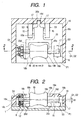
- the rotary electric part D1 constituted as above is mounted to the printed circuit board P1, as shown in Figs. 1 to 5.
- First, second and third push-switches S1, S2, S3, as shown in Figs. 1 to 5, are each made up of a housing 16 which houses a contact portion (not shown) therein and a push-button 17 which is secured to the housing 16 vertically movably and which is urged upwards constantly.
- the push-switches S1 and S2 are mounted on the printed circuit board P1 so as to be orthogonal to the axial direction G1 in the surface direction of the printed circuit board P1 and opposed to each other side by side in parallel with the axial direction G1.
- the push-switch S3 is mounted to the printed circuit board P1 on an extension of the axial direction G1 spacedly a predetermined distance from the rotary electric part D1.
- the operating member 18 which is formed by molding a synthetic resin, comprises a hourglass-like operating portion 18a of a large diameter, cylindrical shafts 18c and 18d smaller in diameter than the operating portion 18a, the shafts 18c and 18d projecting in an axial direction G2 of the operating member 18 from central positions of both side faces 18b of the operating portion 18a, and a hexagonal, non-cylindrical, non-circular portion 18e formed at an end portion of the shaft 18c.
- the shaft 18c of the operating member 18 is inserted into the hole 12a from the mounting plate 12 side while being guided by the cylindrical portion 12h, and the non-circular portion 18e is fitted in the non-circular hole 8f of the rotor 8.
- a case 19 which is formed by molding a synthetic resin, comprises an upper wall 19b having a hole 19a, side walls 19c extending downwards from the outer periphery of the upper wall 19b, and a concave holding portion 19d formed in a side wall 19c.
- the case 19 is mounted to the printed circuit board P1 while covering the rotary electric part D1 and also covering the first, second and third push-switches S1, S2, S3. When the case 19 is thus mounted, part of the operating portion 18a projects outwards from the hole 19a.
- the operating member 18 can perform a rotating motion, a sliding motion in the axial direction G2, and a tilting motion when pushed in a direction orthogonal to the axial direction G2.
- An actuating member 20 which is formed by molding a synthetic resin, comprises a base portion 20a, an arcuate support portion 20b provided at one end of the base portion 20a, and a pair of arm portions 20c and 20d bifurcated from the opposite end of the base portion 20a.
- the actuating member 20 is disposed on the printed circuit board P1 so that its support portion 20b is held by the holding portion 19d of the case 19 and so that the paired arm portions 20c and 20d hold the operating portion 18a therebetween.
- the arm portions 20c and 20d can abut both side faces 18b respectively of the operating portion 18a.
- the paired arm portions 20c and 20d can abut the side faces 18b at positions lower than the operating side (the portion projecting from the hole 19a) of the operating member 18a.
- the arm portions 20c and 20d at the opposite end of the actuating member are adapted to rotate arcuately.
- the operating portion 18a projecting from the hole 19a is rotated with a finger, with consequent rotation of the shafts 18c and 18d and subsequent rotation of the code member 9 together with the rotor 8 through the non-circular portion 18e, so that the contact pieces 6 come into sliding contact with the tongue pieces 9b as code patterns, producing a pulse signal.
- the operating member 18 tilts at a predetermined angle A1 on its shaft 18d side with the rotary electric part D1 as fulcrum, as shown in Figs. 2 and 4, with the result that the push-button 17 of the third push-switch S3 moves downward and the third push-switch S3 is operated (contact ON to OFF or OFF to ON).
- the tilting motion of the operating member 18 is performed in the following manner.
- Fig. 4 when the operating member 18 is pushed, first a lower portion of the shaft 8a of the rotor 8 comes into abutment with the side face of the insulating base 3 which defines the hole 3b.
- the rotor 8 begins to tilt with an abutment portion T1 as fulcrum and at the same time the outermost periphery of the plate portion 9a of the code member 9 abuts the insulating base 1 at an abutment portion T2.
- the rotor 8 tilts at a predetermined angle A2 equal to that of the operating member 18, as shown in Fig. 4, and the mounting plate 12-side portion of the rotor 8 moves to a greater extent than the insulating base 1-side portion thereof, but the presence of the large clearance K2 permits the tilting motion of the rotor 8.
- the code patterns (tongue pieces 9b) extending in the axial direction G1 and the contact pieces 6 disposed perpendicularly thereto are in contact with each other, provided the position of contact of the code patterns with the contact pieces 6 merely shifts downward, and therefore both are kept contacted positively.
- the tongue pieces 9b are less displaced at their contact portions with the contact pieces 6, thus making it difficult to produce unnecessary pulse signals.
- the shaft 18d is guided by a vertical groove (not shown) formed in the case 19 and thus its downward movement can be done accurately.
- the first push-switch S1 is operated (contact ON to OFF or OFF to ON) by the base portion 20a.
- the second push-switch S2 is operated (contact ON to OFF or OFF to ON) by the base portion 20a.
- the multidirectional input device of this embodiment is operated in the manner described above.
- a vertical scrolling operation is performed by the rotary electric device D1
- a transverse scrolling operation is performed by the first and second push-switches S1, S2
- a decision operation is performed by the third push-switch S3.
- the tilting motion of the rotor 8 is conducted with the insulating base 1 as a support member
- the mounting plate 12 or another member may be used as the support member.
- the shafts 18c and 18d may be formed integrally, the shafts 18c and 18d may be formed by a single non-circular shaft and the operating portion 18a may be splined thereto.
- the third push-switch S3 may be omitted.
- the multidirectional input device since one rotary electric part D1 and two first and second push-switches S1, S2 are operated by one operating member 18, a larger number of electric parts than in the prior art can be operated and thus the multidirectional input device of the invention is suitable for use in a portable electronic device for which various functions are required.
- the actuating member 20 has a pair of branched arm portions 20c and 20d and these arm portions are abutted against both side faces 18b at lower positions than the operating side with respect to the operating portion 18a, the actuating member 20 is not an obstacle to the operation of the operating portion 18a and thus the multidirectional input device is superior in operability and can be reduced in thickness.
- the two first and second push-switches S1, S2 are spaced from and opposed to each other and the actuating member 20 is interposed between them, there is attained a good space factor and the multidirectional input device can be further reduced in both thickness and size.
- the moving range of the actuating member 20 is small, thus permitting the reduction in size of the multidirectional input device.
- one end portion of the shaft 18c of the operating member 18 is splined to the rotor 8
- the third push-switch S3 is disposed in opposition to the opposite end portion of the shaft 18d, and when the operating member 18 is pushed in a direction perpendicular to the axial direction G2, the operating member 18 performs a tilting motion and the third push-switch S3 is operated by the shaft 18d. Therefore, a larger number of electric parts can be operated and the multidirectional input device is suitable for use in a portable electronic device for which various functions are required.
- the third push-switch S3 is operated through the shaft 18d by a tilting motion of the operating member 18, the operation is simple and the size of the multidirectional input device can be reduced.
Landscapes
- Engineering & Computer Science (AREA)
- General Engineering & Computer Science (AREA)
- Theoretical Computer Science (AREA)
- Human Computer Interaction (AREA)
- Physics & Mathematics (AREA)
- General Physics & Mathematics (AREA)
- Switches With Compound Operations (AREA)
- Rotary Switch, Piano Key Switch, And Lever Switch (AREA)
- Telephone Set Structure (AREA)
Applications Claiming Priority (2)
| Application Number | Priority Date | Filing Date | Title |
|---|---|---|---|
| JP2000072474 | 2000-03-10 | ||
| JP2000072474A JP3869996B2 (ja) | 2000-03-10 | 2000-03-10 | 多方向入力装置 |
Publications (3)
| Publication Number | Publication Date |
|---|---|
| EP1139273A2 true EP1139273A2 (fr) | 2001-10-04 |
| EP1139273A3 EP1139273A3 (fr) | 2004-04-21 |
| EP1139273B1 EP1139273B1 (fr) | 2007-01-03 |
Family
ID=18590875
Family Applications (1)
| Application Number | Title | Priority Date | Filing Date |
|---|---|---|---|
| EP01302005A Expired - Lifetime EP1139273B1 (fr) | 2000-03-10 | 2001-03-05 | Dispositif d'entrée multidirectionnel |
Country Status (7)
| Country | Link |
|---|---|
| US (1) | US6441325B2 (fr) |
| EP (1) | EP1139273B1 (fr) |
| JP (1) | JP3869996B2 (fr) |
| KR (1) | KR100403431B1 (fr) |
| CN (1) | CN1202541C (fr) |
| DE (1) | DE60125629T2 (fr) |
| TW (1) | TW475189B (fr) |
Families Citing this family (7)
| Publication number | Priority date | Publication date | Assignee | Title |
|---|---|---|---|---|
| JP2001255991A (ja) * | 2000-03-10 | 2001-09-21 | Alps Electric Co Ltd | 入力装置 |
| EP1132855A3 (fr) * | 2000-03-10 | 2005-11-02 | Alps Electric Co., Ltd. | Dispositif d'entrée et appareil électronique portable l'utilisant |
| JP4125931B2 (ja) * | 2002-08-26 | 2008-07-30 | 株式会社ワコー | 回転操作量の入力装置およびこれを利用した操作装置 |
| DE10315721B4 (de) * | 2003-04-04 | 2005-12-08 | Siemens Ag | Bedieneinrichtung für Kraftfahrzeuge mit einer Anzeige, auf der Menüs, Funktionen und Funktionswerte darstellbar und mittels eines Bedienelementes anwählbar und auswählbar sind |
| TW584357U (en) * | 2003-06-24 | 2004-04-11 | Benq Corp | A dial-switch |
| JP4363155B2 (ja) | 2003-10-20 | 2009-11-11 | オムロン株式会社 | 回転・押圧操作型電子部品およびそれを用いた電子機器 |
| ATE534067T1 (de) * | 2008-05-02 | 2011-12-15 | Alps Electric Co Ltd | Multidirektionale eingabevorrichtung |
Citations (3)
| Publication number | Priority date | Publication date | Assignee | Title |
|---|---|---|---|---|
| EP0724278A2 (fr) * | 1995-01-24 | 1996-07-31 | Matsushita Electric Industrial Co., Ltd. | Composant électronique actionné par rotation, avec interrupteur à bouton poussoir |
| EP0855668A2 (fr) * | 1997-01-24 | 1998-07-29 | Matsushita Electric Industrial Co., Ltd. | ContrÔleur multidirectionnel et dispositif de commande multidirectionnel utilisant un tel contrÔleur |
| JPH10326144A (ja) * | 1997-05-27 | 1998-12-08 | Matsushita Electric Ind Co Ltd | 回転操作型電子部品 |
Family Cites Families (16)
| Publication number | Priority date | Publication date | Assignee | Title |
|---|---|---|---|---|
| US4945195A (en) * | 1989-03-20 | 1990-07-31 | C & K Components, Inc. | Rotary switch |
| US5446481A (en) * | 1991-10-11 | 1995-08-29 | Mouse Systems Corporation | Multidimensional hybrid mouse for computers |
| EP0623942A1 (fr) * | 1993-04-20 | 1994-11-09 | FRITZ HARTMANN GERÄTEBAU GMBH & CO KG | Codeur |
| US5606155A (en) * | 1995-02-06 | 1997-02-25 | Garcia; Ricardo L. | Rotary switch |
| US5594220A (en) * | 1995-08-22 | 1997-01-14 | Us Controls Corp. | Rotary switch with cam operated sliding contact engaging noble metal stationary contact bar surface |
| JP3824723B2 (ja) * | 1996-12-27 | 2006-09-20 | アルプス電気株式会社 | 多方向スイッチ |
| JPH10241501A (ja) * | 1997-02-25 | 1998-09-11 | Matsushita Electric Ind Co Ltd | プッシュスイッチ付複合操作型電子部品 |
| TW369658B (en) | 1997-03-13 | 1999-09-11 | Alps Electric Co Ltd | Rotary operation electric components and the coordinate input apparatus using the rotary operation electric components |
| JPH1139998A (ja) * | 1997-07-16 | 1999-02-12 | Matsushita Electric Ind Co Ltd | 回転型エンコーダ |
| JP3694392B2 (ja) * | 1997-08-22 | 2005-09-14 | アルプス電気株式会社 | 複合操作型電気部品 |
| JPH11121210A (ja) * | 1997-10-08 | 1999-04-30 | Alps Electric Co Ltd | プッシュスイッチ付回転型電気部品 |
| JP3911800B2 (ja) * | 1997-11-10 | 2007-05-09 | 松下電器産業株式会社 | 多方向操作スイッチ |
| JP3766207B2 (ja) * | 1998-05-25 | 2006-04-12 | アルプス電気株式会社 | 複合操作型電気部品 |
| JP3837926B2 (ja) * | 1998-07-30 | 2006-10-25 | 松下電器産業株式会社 | 回転形電子部品およびこれを用いた電子機器 |
| JP3951485B2 (ja) * | 1998-12-25 | 2007-08-01 | 松下電器産業株式会社 | 回転・押圧操作型電子部品およびそれを用いた電子機器 |
| TW508606B (en) * | 1999-07-27 | 2002-11-01 | Alps Electric Co Ltd | Multi-directional input device |
-
2000
- 2000-03-10 JP JP2000072474A patent/JP3869996B2/ja not_active Expired - Fee Related
-
2001
- 2001-02-06 TW TW090102547A patent/TW475189B/zh active
- 2001-03-05 DE DE60125629T patent/DE60125629T2/de not_active Expired - Fee Related
- 2001-03-05 EP EP01302005A patent/EP1139273B1/fr not_active Expired - Lifetime
- 2001-03-05 CN CNB011093692A patent/CN1202541C/zh not_active Expired - Fee Related
- 2001-03-07 US US09/800,617 patent/US6441325B2/en not_active Expired - Fee Related
- 2001-03-09 KR KR10-2001-0012267A patent/KR100403431B1/ko not_active IP Right Cessation
Patent Citations (3)
| Publication number | Priority date | Publication date | Assignee | Title |
|---|---|---|---|---|
| EP0724278A2 (fr) * | 1995-01-24 | 1996-07-31 | Matsushita Electric Industrial Co., Ltd. | Composant électronique actionné par rotation, avec interrupteur à bouton poussoir |
| EP0855668A2 (fr) * | 1997-01-24 | 1998-07-29 | Matsushita Electric Industrial Co., Ltd. | ContrÔleur multidirectionnel et dispositif de commande multidirectionnel utilisant un tel contrÔleur |
| JPH10326144A (ja) * | 1997-05-27 | 1998-12-08 | Matsushita Electric Ind Co Ltd | 回転操作型電子部品 |
Non-Patent Citations (1)
| Title |
|---|
| PATENT ABSTRACTS OF JAPAN vol. 1999, no. 03, 31 March 1999 (1999-03-31) & JP 10 326144 A (MATSUSHITA ELECTRIC IND CO LTD), 8 December 1998 (1998-12-08) * |
Also Published As
| Publication number | Publication date |
|---|---|
| TW475189B (en) | 2002-02-01 |
| EP1139273A3 (fr) | 2004-04-21 |
| CN1202541C (zh) | 2005-05-18 |
| US6441325B2 (en) | 2002-08-27 |
| JP3869996B2 (ja) | 2007-01-17 |
| DE60125629T2 (de) | 2007-10-04 |
| EP1139273B1 (fr) | 2007-01-03 |
| KR20010091949A (ko) | 2001-10-23 |
| DE60125629D1 (de) | 2007-02-15 |
| US20010020573A1 (en) | 2001-09-13 |
| CN1313621A (zh) | 2001-09-19 |
| JP2001256866A (ja) | 2001-09-21 |
| KR100403431B1 (ko) | 2003-10-30 |
Similar Documents
| Publication | Publication Date | Title |
|---|---|---|
| JP3222714B2 (ja) | 押圧・回転操作型電子部品 | |
| JP4487821B2 (ja) | 複合操作型電子部品 | |
| JP4882842B2 (ja) | 多方向入力装置 | |
| EP1139273B1 (fr) | Dispositif d'entrée multidirectionnel | |
| JP2007123459A (ja) | 回転型電気部品 | |
| JP2001325859A (ja) | 複合操作型スイッチ装置 | |
| JP2005158328A (ja) | 回転操作型電子部品 | |
| JP3763711B2 (ja) | 複合操作型電子部品 | |
| EP1132856A1 (fr) | Dispositif d'entrée et dispositif électronique portable avec un tel dispositif | |
| JP4213019B2 (ja) | 多方向入力装置 | |
| JP2005259634A (ja) | 回転型電気部品 | |
| EP1132855A2 (fr) | Dispositif d'entrée et appareil électronique portable l'utilisant | |
| JP2001345031A (ja) | 複合操作型電子部品 | |
| JP4030391B2 (ja) | 多方向入力装置 | |
| KR100399457B1 (ko) | 스위치장치 | |
| JP2001325860A (ja) | 複合操作型スイッチ装置 | |
| WO2005038843A1 (fr) | Composant electronique du type fonctionnant par rotation et pression et dispositif electronique comportant ledit composant | |
| EP0918344A2 (fr) | Interrupteur et dispositifs électroniques utilisant cet interrupteur | |
| JP3770768B2 (ja) | 多方向入力装置 | |
| JP2001332155A (ja) | 多方向入力装置 | |
| JP3780119B2 (ja) | 入力装置 | |
| JP2001255990A (ja) | 入力装置 | |
| JP2001265508A (ja) | 入力装置、及びこの入力装置を使用した携帯用電子機器 | |
| JP2001357751A (ja) | 複合スイッチ | |
| JP3964093B2 (ja) | スイッチ装置 |
Legal Events
| Date | Code | Title | Description |
|---|---|---|---|
| PUAI | Public reference made under article 153(3) epc to a published international application that has entered the european phase |
Free format text: ORIGINAL CODE: 0009012 |
|
| AK | Designated contracting states |
Kind code of ref document: A2 Designated state(s): AT BE CH CY DE DK ES FI FR GB GR IE IT LI LU MC NL PT SE TR |
|
| AX | Request for extension of the european patent |
Free format text: AL;LT;LV;MK;RO;SI |
|
| PUAL | Search report despatched |
Free format text: ORIGINAL CODE: 0009013 |
|
| AK | Designated contracting states |
Kind code of ref document: A3 Designated state(s): AT BE CH CY DE DK ES FI FR GB GR IE IT LI LU MC NL PT SE TR |
|
| AX | Request for extension of the european patent |
Extension state: AL LT LV MK RO SI |
|
| 17P | Request for examination filed |
Effective date: 20040522 |
|
| 17Q | First examination report despatched |
Effective date: 20041122 |
|
| AKX | Designation fees paid |
Designated state(s): DE FI FR GB SE |
|
| RIC1 | Information provided on ipc code assigned before grant |
Ipc: G06F 3/033 20060101AFI20060120BHEP |
|
| GRAP | Despatch of communication of intention to grant a patent |
Free format text: ORIGINAL CODE: EPIDOSNIGR1 |
|
| GRAS | Grant fee paid |
Free format text: ORIGINAL CODE: EPIDOSNIGR3 |
|
| GRAA | (expected) grant |
Free format text: ORIGINAL CODE: 0009210 |
|
| AK | Designated contracting states |
Kind code of ref document: B1 Designated state(s): DE FI FR GB SE |
|
| PG25 | Lapsed in a contracting state [announced via postgrant information from national office to epo] |
Ref country code: FI Free format text: LAPSE BECAUSE OF FAILURE TO SUBMIT A TRANSLATION OF THE DESCRIPTION OR TO PAY THE FEE WITHIN THE PRESCRIBED TIME-LIMIT Effective date: 20070103 |
|
| REG | Reference to a national code |
Ref country code: GB Ref legal event code: FG4D |
|
| REF | Corresponds to: |
Ref document number: 60125629 Country of ref document: DE Date of ref document: 20070215 Kind code of ref document: P |
|
| PG25 | Lapsed in a contracting state [announced via postgrant information from national office to epo] |
Ref country code: SE Free format text: LAPSE BECAUSE OF FAILURE TO SUBMIT A TRANSLATION OF THE DESCRIPTION OR TO PAY THE FEE WITHIN THE PRESCRIBED TIME-LIMIT Effective date: 20070403 |
|
| ET | Fr: translation filed | ||
| PLBE | No opposition filed within time limit |
Free format text: ORIGINAL CODE: 0009261 |
|
| STAA | Information on the status of an ep patent application or granted ep patent |
Free format text: STATUS: NO OPPOSITION FILED WITHIN TIME LIMIT |
|
| 26N | No opposition filed |
Effective date: 20071005 |
|
| PGFP | Annual fee paid to national office [announced via postgrant information from national office to epo] |
Ref country code: GB Payment date: 20090105 Year of fee payment: 9 |
|
| PGFP | Annual fee paid to national office [announced via postgrant information from national office to epo] |
Ref country code: DE Payment date: 20090528 Year of fee payment: 9 |
|
| PGFP | Annual fee paid to national office [announced via postgrant information from national office to epo] |
Ref country code: FR Payment date: 20090114 Year of fee payment: 9 |
|
| GBPC | Gb: european patent ceased through non-payment of renewal fee |
Effective date: 20100305 |
|
| REG | Reference to a national code |
Ref country code: FR Ref legal event code: ST Effective date: 20101130 |
|
| PG25 | Lapsed in a contracting state [announced via postgrant information from national office to epo] |
Ref country code: FR Free format text: LAPSE BECAUSE OF NON-PAYMENT OF DUE FEES Effective date: 20100331 |
|
| PG25 | Lapsed in a contracting state [announced via postgrant information from national office to epo] |
Ref country code: DE Free format text: LAPSE BECAUSE OF NON-PAYMENT OF DUE FEES Effective date: 20101001 |
|
| PG25 | Lapsed in a contracting state [announced via postgrant information from national office to epo] |
Ref country code: GB Free format text: LAPSE BECAUSE OF NON-PAYMENT OF DUE FEES Effective date: 20100305 |