EP1138928A2 - Moteur turbo-suralimenté avec recirculation de gaz d'échappement - Google Patents
Moteur turbo-suralimenté avec recirculation de gaz d'échappement Download PDFInfo
- Publication number
- EP1138928A2 EP1138928A2 EP01107602A EP01107602A EP1138928A2 EP 1138928 A2 EP1138928 A2 EP 1138928A2 EP 01107602 A EP01107602 A EP 01107602A EP 01107602 A EP01107602 A EP 01107602A EP 1138928 A2 EP1138928 A2 EP 1138928A2
- Authority
- EP
- European Patent Office
- Prior art keywords
- line
- exhaust
- engine
- point
- turbine
- Prior art date
- Legal status (The legal status is an assumption and is not a legal conclusion. Google has not performed a legal analysis and makes no representation as to the accuracy of the status listed.)
- Granted
Links
Images

Classifications
-
- F—MECHANICAL ENGINEERING; LIGHTING; HEATING; WEAPONS; BLASTING
- F02—COMBUSTION ENGINES; HOT-GAS OR COMBUSTION-PRODUCT ENGINE PLANTS
- F02B—INTERNAL-COMBUSTION PISTON ENGINES; COMBUSTION ENGINES IN GENERAL
- F02B37/00—Engines characterised by provision of pumps driven at least for part of the time by exhaust
- F02B37/04—Engines with exhaust drive and other drive of pumps, e.g. with exhaust-driven pump and mechanically-driven second pump
- F02B37/10—Engines with exhaust drive and other drive of pumps, e.g. with exhaust-driven pump and mechanically-driven second pump at least one pump being alternatively or simultaneously driven by exhaust and other drive, e.g. by pressurised fluid from a reservoir or an engine-driven pump
-
- F—MECHANICAL ENGINEERING; LIGHTING; HEATING; WEAPONS; BLASTING
- F02—COMBUSTION ENGINES; HOT-GAS OR COMBUSTION-PRODUCT ENGINE PLANTS
- F02B—INTERNAL-COMBUSTION PISTON ENGINES; COMBUSTION ENGINES IN GENERAL
- F02B37/00—Engines characterised by provision of pumps driven at least for part of the time by exhaust
- F02B37/005—Exhaust driven pumps being combined with an exhaust driven auxiliary apparatus, e.g. a ventilator
-
- F—MECHANICAL ENGINEERING; LIGHTING; HEATING; WEAPONS; BLASTING
- F02—COMBUSTION ENGINES; HOT-GAS OR COMBUSTION-PRODUCT ENGINE PLANTS
- F02B—INTERNAL-COMBUSTION PISTON ENGINES; COMBUSTION ENGINES IN GENERAL
- F02B37/00—Engines characterised by provision of pumps driven at least for part of the time by exhaust
- F02B37/12—Control of the pumps
- F02B37/16—Control of the pumps by bypassing charging air
-
- F—MECHANICAL ENGINEERING; LIGHTING; HEATING; WEAPONS; BLASTING
- F02—COMBUSTION ENGINES; HOT-GAS OR COMBUSTION-PRODUCT ENGINE PLANTS
- F02M—SUPPLYING COMBUSTION ENGINES IN GENERAL WITH COMBUSTIBLE MIXTURES OR CONSTITUENTS THEREOF
- F02M26/00—Engine-pertinent apparatus for adding exhaust gases to combustion-air, main fuel or fuel-air mixture, e.g. by exhaust gas recirculation [EGR] systems
- F02M26/13—Arrangement or layout of EGR passages, e.g. in relation to specific engine parts or for incorporation of accessories
- F02M26/17—Arrangement or layout of EGR passages, e.g. in relation to specific engine parts or for incorporation of accessories in relation to the intake system
- F02M26/19—Means for improving the mixing of air and recirculated exhaust gases, e.g. venturis or multiple openings to the intake system
-
- F—MECHANICAL ENGINEERING; LIGHTING; HEATING; WEAPONS; BLASTING
- F02—COMBUSTION ENGINES; HOT-GAS OR COMBUSTION-PRODUCT ENGINE PLANTS
- F02B—INTERNAL-COMBUSTION PISTON ENGINES; COMBUSTION ENGINES IN GENERAL
- F02B37/00—Engines characterised by provision of pumps driven at least for part of the time by exhaust
- F02B37/007—Engines characterised by provision of pumps driven at least for part of the time by exhaust with exhaust-driven pumps arranged in parallel, e.g. at least one pump supplying alternatively
-
- F—MECHANICAL ENGINEERING; LIGHTING; HEATING; WEAPONS; BLASTING
- F02—COMBUSTION ENGINES; HOT-GAS OR COMBUSTION-PRODUCT ENGINE PLANTS
- F02M—SUPPLYING COMBUSTION ENGINES IN GENERAL WITH COMBUSTIBLE MIXTURES OR CONSTITUENTS THEREOF
- F02M26/00—Engine-pertinent apparatus for adding exhaust gases to combustion-air, main fuel or fuel-air mixture, e.g. by exhaust gas recirculation [EGR] systems
- F02M26/02—EGR systems specially adapted for supercharged engines
- F02M26/04—EGR systems specially adapted for supercharged engines with a single turbocharger
- F02M26/05—High pressure loops, i.e. wherein recirculated exhaust gas is taken out from the exhaust system upstream of the turbine and reintroduced into the intake system downstream of the compressor
-
- F—MECHANICAL ENGINEERING; LIGHTING; HEATING; WEAPONS; BLASTING
- F02—COMBUSTION ENGINES; HOT-GAS OR COMBUSTION-PRODUCT ENGINE PLANTS
- F02M—SUPPLYING COMBUSTION ENGINES IN GENERAL WITH COMBUSTIBLE MIXTURES OR CONSTITUENTS THEREOF
- F02M26/00—Engine-pertinent apparatus for adding exhaust gases to combustion-air, main fuel or fuel-air mixture, e.g. by exhaust gas recirculation [EGR] systems
- F02M26/02—EGR systems specially adapted for supercharged engines
- F02M26/04—EGR systems specially adapted for supercharged engines with a single turbocharger
- F02M26/06—Low pressure loops, i.e. wherein recirculated exhaust gas is taken out from the exhaust downstream of the turbocharger turbine and reintroduced into the intake system upstream of the compressor
-
- F—MECHANICAL ENGINEERING; LIGHTING; HEATING; WEAPONS; BLASTING
- F02—COMBUSTION ENGINES; HOT-GAS OR COMBUSTION-PRODUCT ENGINE PLANTS
- F02M—SUPPLYING COMBUSTION ENGINES IN GENERAL WITH COMBUSTIBLE MIXTURES OR CONSTITUENTS THEREOF
- F02M26/00—Engine-pertinent apparatus for adding exhaust gases to combustion-air, main fuel or fuel-air mixture, e.g. by exhaust gas recirculation [EGR] systems
- F02M26/02—EGR systems specially adapted for supercharged engines
- F02M26/08—EGR systems specially adapted for supercharged engines for engines having two or more intake charge compressors or exhaust gas turbines, e.g. a turbocharger combined with an additional compressor
-
- F—MECHANICAL ENGINEERING; LIGHTING; HEATING; WEAPONS; BLASTING
- F02—COMBUSTION ENGINES; HOT-GAS OR COMBUSTION-PRODUCT ENGINE PLANTS
- F02M—SUPPLYING COMBUSTION ENGINES IN GENERAL WITH COMBUSTIBLE MIXTURES OR CONSTITUENTS THEREOF
- F02M26/00—Engine-pertinent apparatus for adding exhaust gases to combustion-air, main fuel or fuel-air mixture, e.g. by exhaust gas recirculation [EGR] systems
- F02M26/13—Arrangement or layout of EGR passages, e.g. in relation to specific engine parts or for incorporation of accessories
- F02M26/22—Arrangement or layout of EGR passages, e.g. in relation to specific engine parts or for incorporation of accessories with coolers in the recirculation passage
- F02M26/23—Layout, e.g. schematics
- F02M26/25—Layout, e.g. schematics with coolers having bypasses
-
- F—MECHANICAL ENGINEERING; LIGHTING; HEATING; WEAPONS; BLASTING
- F02—COMBUSTION ENGINES; HOT-GAS OR COMBUSTION-PRODUCT ENGINE PLANTS
- F02M—SUPPLYING COMBUSTION ENGINES IN GENERAL WITH COMBUSTIBLE MIXTURES OR CONSTITUENTS THEREOF
- F02M26/00—Engine-pertinent apparatus for adding exhaust gases to combustion-air, main fuel or fuel-air mixture, e.g. by exhaust gas recirculation [EGR] systems
- F02M26/13—Arrangement or layout of EGR passages, e.g. in relation to specific engine parts or for incorporation of accessories
- F02M26/38—Arrangement or layout of EGR passages, e.g. in relation to specific engine parts or for incorporation of accessories with two or more EGR valves disposed in parallel
-
- F—MECHANICAL ENGINEERING; LIGHTING; HEATING; WEAPONS; BLASTING
- F02—COMBUSTION ENGINES; HOT-GAS OR COMBUSTION-PRODUCT ENGINE PLANTS
- F02M—SUPPLYING COMBUSTION ENGINES IN GENERAL WITH COMBUSTIBLE MIXTURES OR CONSTITUENTS THEREOF
- F02M26/00—Engine-pertinent apparatus for adding exhaust gases to combustion-air, main fuel or fuel-air mixture, e.g. by exhaust gas recirculation [EGR] systems
- F02M26/13—Arrangement or layout of EGR passages, e.g. in relation to specific engine parts or for incorporation of accessories
- F02M26/42—Arrangement or layout of EGR passages, e.g. in relation to specific engine parts or for incorporation of accessories having two or more EGR passages; EGR systems specially adapted for engines having two or more cylinders
-
- Y—GENERAL TAGGING OF NEW TECHNOLOGICAL DEVELOPMENTS; GENERAL TAGGING OF CROSS-SECTIONAL TECHNOLOGIES SPANNING OVER SEVERAL SECTIONS OF THE IPC; TECHNICAL SUBJECTS COVERED BY FORMER USPC CROSS-REFERENCE ART COLLECTIONS [XRACs] AND DIGESTS
- Y02—TECHNOLOGIES OR APPLICATIONS FOR MITIGATION OR ADAPTATION AGAINST CLIMATE CHANGE
- Y02T—CLIMATE CHANGE MITIGATION TECHNOLOGIES RELATED TO TRANSPORTATION
- Y02T10/00—Road transport of goods or passengers
- Y02T10/10—Internal combustion engine [ICE] based vehicles
- Y02T10/12—Improving ICE efficiencies
Definitions
- the present invention relates generally to the field of internal combustion engines and, more particularly, to turbocharged internal combustion engines with exhaust gas recirculation (EGR).
- EGR exhaust gas recirculation
- Turbocharging is a well known method for increasing power output from an internal combustion engine.
- a turbine uses energy from exhaust gases to power a compressor. This increases the pressure of the air supplied to the engine so that higher cylinder pressure can be achieved thereby improving the performance of the engine.
- EGR exhaust gas recirculation
- turbocharged internal combustion engines with EGR are known in the art.
- a compressor is driven by a turbine connected to the exhaust manifold to pressurize intake air for the engine, and an EGR manifold is connected between the exhaust manifold and the intake manifold to recycle exhaust gases back to the engine to reduce emissions.
- the EGR manifold includes a one-way valve or a series of valve arrangements to prevent the pressurized intake manifold air from backflowing into the exhaust manifold, and an EGR control system monitors the differential pressure between the intake and exhaust manifolds. When a predetermined pressure differential is established between the intake and exhaust manifolds, the EGR manifold valve opens to recycle exhaust gases.
- a disadvantage of turbocharged internal combustion engines with EGR of the above type is that diversion of exhaust gases through the EGR manifold tends to reduce air flow through the compressor. Since compressor map width (i.e., the range of mass air flow over which the compressor is fully functional) decreases with increasing compressor pressure ratio for a given engine speed, any reduction in air flow through the compressor will tend to result in a reduction in surge margin thereby increasing the likelihood of compressor malfunction when there are changes in the air inlet temperature and/or the amount of air flowing through the compressor especially at low engine speeds. Compressor choke problems can also occur at rated load and speed.
- a bypass line extends from the intake manifold to a combustion chamber from which it separates into two branches that connect with the exhaust manifold and the EGR manifold, respectively, so that intensely preheated gas from the combustion chamber can be mixed with recycled exhaust gases to overcome unfavorable ignition conditions. While this approach may improve the ability of an engine to start under extreme conditions, the addition of a combustion chamber increases the cost and complexity of the system and may also reduce efficiency and surge margin by significantly increasing pressure ratios.
- a turbocharged internal combustion engine assembly with exhaust gas recirculation including an air compressor driven by an exhaust turbine, an air intake line for conveying air from the compressor to the engine, an exhaust line for conveying exhaust gas from the engine to the exhaust turbine, an EGR line extending from a first point on the exhaust line downstream of the engine to a second point on the air intake line upstream of the engine, a combustion bypass line extending from a third point on the air intake line upstream of the exhaust gas recirculation line to a fourth point on the exhaust line downstream of the exhaust gas recirculation line, and a pressure adjusting feature disposed along at least one of the air intake line and the exhaust line to maintain the pressure at the fourth point below the pressure at the third point and above the pressure at the second point.
- EGR exhaust gas recirculation
- Suitable pressure adjusting features include a venturi placed in the air intake line at the second point, a power turbine located along the exhaust line downstream of the exhaust turbine, a split exhaust manifold feeding unequal turbine inlets, and an orifice located along the exhaust line between the EGR line and the bypass line.
- Another aspect of the present invention is generally characterized in a method of operating a turbocharged engine assembly with exhaust gas recirculation including the steps of feeding exhaust gas from the engine to an exhaust turbine via an exhaust line, compressing air with an air compressor powered by the exhaust turbine, feeding compressed air from the air compressor to the engine via an air intake line, providing an exhaust gas recirculation line between a first point on the exhaust line downstream of the engine and a second point on the air intake line upstream of the engine, providing a combustion bypass line between a third point on the air intake line upstream of the second point and a fourth point on the exhaust line downstream of the first point, and adjusting the pressure in at least one of the air intake line and the exhaust line such that the pressure at the fourth point is below the pressure at the third point and above the pressure at the second point so that a first portion of the exhaust gas from the engine is mixed with a first portion of the compressed air from the compressor for combustion in the engine and a second portion of the compressed air is diverted from the air intake line to the exhaust line without being combusted
- the pressure adjusting step includes the step of passing the first compressed air portion through a venturi so that the second exhaust gas portion is mixed with the first compressed air portion in the venturi.
- the pressure adjusting step includes the step of driving a power turbine with exhaust gases from the exhaust turbine via an extension of the exhaust line and connecting the combustion bypass line with the exhaust line extension.
- the pressure adjusting step includes the steps of feeding exhaust gases from a first set of cylinders to a first turbine inlet and feeding exhaust gases from a second set of cylinders to a second turbine inlet.
- the pressure adjusting step includes the step of passing exhaust gases from the engine through an orifice in the exhaust line such that the pressure downstream of the orifice is lower than the pressure upstream of the orifice.
- Some of the advantages of the present invention over the prior art include the ability to operate a turbocharged engine with EGR at lower engine speeds without surge problems and at rated load and speed without compressor choke problems, improvement in air to fuel ratio, simplified construction, and increased power output.
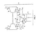
- FIG. 1 A first embodiment of a turbocharged internal combustion engine assembly 10 with exhaust gas recirculation (EGR) according to the present invention is shown in FIG. 1.
- the engine assembly 10 includes an internal combustion engine 12 with at least one cylinder in communication with an air inlet 14 and an exhaust gas outlet 16, and a turbocharger having an air compressor 18 driven by an exhaust turbine 20.
- the compressor includes an air inlet 17 and a compressed air outlet 19.
- the exhaust turbine includes a gas inlet 21 and a gas outlet 23.
- An air intake line 22 leads from the compressor outlet to the engine inlet via a first cooler 24, and an exhaust line 26 leads from the engine outlet to the exhaust turbine inlet.
- An EGR line 28 for recycling exhaust gases branches off from a first point 30 on the exhaust line to connect with the air intake line at a second point 32 via a second cooler 34.
- a valve 36 is provided along the EGR line upstream of the second cooler to control the amount of exhaust gas that is recycled through the engine.
- a combustion bypass line 38 is connected between the compressor outlet 19 and the turbine inlet 21, and the turbine inlet geometry is chosen such that the pressure at the inlet is lower than the pressure at the compressor outlet so that compressed air can be made to flow from the compressor directly to the turbine without combustion. More specifically, the bypass line 38 extends from a third point 40 on the intake line 22 upstream from the second point 32 to a fourth point 42 on the exhaust line 26 downstream of the first point 30. A valve 44 is provided along the combustion bypass line 38 to control the amount of compressed air flowing from the compressor 18 to the turbine 20.
- a venturi 46 is disposed along the air intake line 22 downstream of the cooler 24 and the EGR line 28 is connected with the air intake line at the venturi.
- an engine control unit (not shown) preferably monitors one or more operating parameters of the engine (e.g., air flow, compressor pressure ratio, engine speed, etc.) and controls the valves 36 and 44 based on certain predetermined conditions.
- the engine control unit preferably includes a microprocessor configured to receive signals from sensors measuring engine operating parameters, to determine whether certain predetermined conditions exist using the measured parameters, and to output signals that control the valves in an appropriate manner.
- various electrical, mechanical and electromechanical control mechanisms can be used to control the valves in response to predetermined conditions.
- the engine 10 is preferably started with the bypass valve 44 and the EGR valve 36 closed; although, in a less preferred embodiment, one or both of these valves can be left open when starting the engine.
- Air initially drawn into the engine 10 when starting the engine will flow through the compressor 18 into the air intake line 22 without being charged (i.e., compressed).
- the air intake line 22 conveys the air into the engine (i.e., cylinder 12) where the air is then mixed with fuel and combusted to move a piston disposed within the cylinder.
- the resulting exhaust gases are expelled from the engine into the exhaust line 26 which conveys the exhaust gases to the turbine 20.
- the exhaust gases act on vanes within the turbine 20 to induce the turbine shaft to rotate. Rotation of the turbine shaft by the exhaust gases drives the compressor 18 so that air subsequently flowing through the compressor can be compressed before it enters the air intake line 22.
- the EGR valve 36 is preferably opened to recycle a portion of the exhaust gases back through the engine. More specifically, a portion of the exhaust gas discharged from the engine is diverted from the first point 30 along the exhaust line 26 and conveyed through the EGR cooler 34 to the second point 32 on the intake line 22. The recycled exhaust gas then mixes with compressed air in the intake line 22 and is fed to the engine for combustion. In this manner, exhaust species which are still rich in nitrogen are reintroduced to the engine, lowering NO x emissions levels by lowering flame temperature.
- Recirculation of exhaust gases in the above manner can reduce air flow through the compressor such that surge margin becomes a concern. This is particularly true when operating at relatively high compressor pressure ratios (e.g., greater than about 3.5:1 ) and lower engine speeds.
- air flow through the compressor can be increased by opening the bypass valve 44.
- the engine control unit can be configured to open the bypass valve 44 when the surge margin is less than or equal to about 10% of the compressor map width.
- the turbine inlet geometry is chosen such that, when the bypass valve 44 is open, the pressure at the turbine inlet 21 will be lower than the pressure at the compressor outlet 19 so that a portion of the compressed air from the compressor 18 will flow directly into the exhaust turbine 20 from the compressor via the bypass line 38.
- This increases air flow through the compressor 18 thereby increasing surge margin to an acceptable level, even at low engine speeds.
- Opening the bypass valve 44 can also cause the pressure at the turbine inlet 21 to decrease; however, the compressed air that is not diverted through the bypass line 38 is subsequently cooled and passed through the venturi 46 where it is accelerated to reduce the pressure in the intake line 22 below the turbine inlet pressure so that exhaust gases continue to be diverted from the exhaust line 26 into the EGR line 28.
- the diverted exhaust gas passes through the EGR cooler 34 and into the intake manifold via the venturi 46, to mix with incoming air for combustion in the engine. Emissions from the engine are thus reduced without the significant reductions in air flow normally seen in turbocharged engines with EGR. This ensures sufficient surge margin to permit operation over a range of inlet air temperatures and to accommodate periodic changes in air flow.
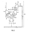
- FIG 2 A second embodiment of a turbocharged internal combustion engine assembly with EGR according to the present invention is shown in FIG 2 at 50.
- the engine assembly in this second embodiment includes an engine 12 with at least one cylinder, and a turbocharger having an air compressor 18 driven by an exhaust turbine 20.
- the engine assembly also includes an air intake line 22 with a main cooler 24 that leads from the compressor outlet 19 to the engine inlet 14, an exhaust line 26 that leads from the engine outlet 16 to the exhaust turbine inlet 21, and a return line 28 with an EGR cooler 34 branching off from a first point 30 along the exhaust line and connecting with the air intake line at a point 32 upstream of the engine.
- the engine assembly in this second embodiment does not include a venturi and the combustion bypass line 38 extends directly from a point 40 along the air intake line 22 to a point 42 along an extension 52 of the exhaust line extending from the exhaust turbine outlet 23 to the inlet 54 of a power turbine 56.
- the power turbine 56 includes a shaft 57 that can optionally be coupled with the drive shaft of the engine to provide additional power to the engine.
- a valve 44 in the combustion bypass line 38 controls the amount of compressed air allowed to flow through the bypass line.
- pressure in the exhaust line 26 at the turbine inlet 21 will be greater than pressure in the air intake line 22 downstream of the cooler 24 so that exhaust gases will tend to flow through the EGR line 28 when the EGR valve 36 is open.
- expansion of the exhaust gases in the exhaust turbine 20 will result in a lowering of the pressure at the turbine outlet 23 such that the pressure in the turbine exhaust line 52 is lower than the pressure in the air intake line 22 thereby promoting the flow of compressed air from the compressor 18 to the turbine exhaust line when the combustion bypass valve 44 is open. This increases air flow through the compressor as in the previous embodiment thereby increasing efficiency and surge margin.
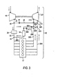
- FIG. 3 A third embodiment of a turbocharged internal combustion engine assembly with EGR according to the present invention is shown in FIG. 3 at 60.
- the engine assembly in this third embodiment includes an engine 12 with a plurality of cylinders, and a turbocharger having an air compressor 18 driven by an exhaust turbine 20.
- the engine assembly also includes an air inlet line 22 with a main cooler 24 that leads from the compressor 18 to the engine.
- a plurality of exhaust lines lead from the engine to the turbine and a corresponding number of EGR return lines lead from the respective exhaust lines to the air inlet line via an EGR cooler.
- a first exhaust line 26A leads from a first set of cylinders 12A to a first, high pressure inlet 21A of the turbine and a second exhaust line 26B leads from a second set of cylinders 12B to a second, low pressure inlet 21B of the turbine.
- the combustion bypass line 38 extends directly from the third point 40 along the air inlet line 22 to a fourth point 42A along the first exhaust line 26A.
- the EGR return lines 28A and 28B extend from points 30A and 30B along respective exhaust lines 26A and 26B to a common EGR cooler 34 and continue as a single return line 28C from the cooler to the second point 32 along the air intake line 22. Valves 36A and 36B control the flow of exhaust gases through the exhaust lines 26A and 26B, respectively.
- first turbine inlet nozzle 21A Due to the smaller turbine inlet area of the first turbine inlet nozzle 21A, pressure in the first exhaust line 26A will be higher than pressure in the second exhaust line 26B; however, the geometry of the first turbine inlet nozzle is chosen such that the pressure in the first exhaust line is lower than the pressure at the compressor outlet 19 so that compressed air will flow through the combustion bypass line 38 to the exhaust turbine 20 when the combustion bypass valve 44 is open. In addition, the geometry of the second turbine inlet nozzle 21B is chosen such that the pressure in the second exhaust line 26B at point 30B is higher than the pressure in the air intake line 22 at point 32 so that exhaust gases will flow through the second EGR line 28B when the second EGR valve 36B is open.
- the second EGR valve 36B is opened in the second EGR line 28B. Then, the combustion bypass valve 44 can be opened. Since the pressure in the first exhaust line 26A is already higher than in the second exhaust line 26B, exhaust gases will flow through the first EGR line 28A when the EGR valve 36A is opened causing a greater portion of the exhaust gases to be recycled.
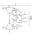
- FIG. 4 A fourth embodiment of a turbocharged internal combustion engine assembly with EGR according to the present invention is shown in FIG. 4 at 70.
- the engine assembly in this fourth embodiment includes an engine 12 with one or more cylinders, and a turbocharger having an air compressor 18 driven by an exhaust turbine 20.
- the engine assembly also includes an air inlet line 22 with a main cooler 24 that leads from the compressor outlet 19 to the engine inlet 14, an exhaust line 26 that leads from the engine outlet 16 to the exhaust turbine inlet 21, and an EGR return line 28 with a cooler 34 branching off from a first point 30 along the exhaust line and connecting with the air inlet line at a point 32 upstream of the engine.
- the engine assembly also includes a combustion bypass line 38 with a valve 44 extending from a third point 40 along the air intake line 22 to a fourth point 42 along the exhaust line.
- the engine assembly in this fourth embodiment does not include a venturi and is provided with an orifice 72 in the exhaust line 26.
- the orifice 72 is located at a point along the exhaust line 26 between the first and fourth points 30 and 42 corresponding to the upstream end of the EGR return line and the downstream end of the combustion bypass line, respectively.
- a venturi 46 is provided in the air intake line 22 to counteract the effect of the bypass line on the flow of exhaust gases through the EGR line 28
- a valved bypass line 74 can extend around the venturi as shown by broken lines in FIG. 5 to allow compressed air to flow into the engine without passing through the venturi if the pressure is already low enough after the main cooler to induce flow through the EGR line.
- one or more additional combustion bypass lines can be provided between the inlet air line and the exhaust line.
- respective bypass lines can terminate upstream and downstream of the turbine.
- turbocharged diesel engines as shown or in any other type of turbocharged internal combustion engine.
- the engine can have any number of cylinders.
- turbocharger can be a single stage turbocharger, a compound turbocharger, a series turbocharger, or any other type of turbocharger.
- the exhaust turbine can have a fixed inlet nozzle geometry or a variable inlet nozzle geometry.
- suitable coolers for use in the air intake and/or EGR lines include, without limitation, shell and tube type coolers and fin and plate type coolers.
- suitable valves for use in the EGR and/or bypass lines include modulated poppet-type valves, proportional solenoid valves and butterfly-type valves.
- any of the embodiments can be modified to include a venturi, a power turbine, a split exhaust manifold and/or an orifice as described above.
Landscapes
- Engineering & Computer Science (AREA)
- Chemical & Material Sciences (AREA)
- Combustion & Propulsion (AREA)
- Mechanical Engineering (AREA)
- General Engineering & Computer Science (AREA)
- Supercharger (AREA)
- Exhaust-Gas Circulating Devices (AREA)
Applications Claiming Priority (2)
| Application Number | Priority Date | Filing Date | Title |
|---|---|---|---|
| US19232300P | 2000-03-27 | 2000-03-27 | |
| US192323P | 2000-03-27 |
Publications (3)
| Publication Number | Publication Date |
|---|---|
| EP1138928A2 true EP1138928A2 (fr) | 2001-10-04 |
| EP1138928A3 EP1138928A3 (fr) | 2002-08-07 |
| EP1138928B1 EP1138928B1 (fr) | 2013-04-24 |
Family
ID=22709174
Family Applications (1)
| Application Number | Title | Priority Date | Filing Date |
|---|---|---|---|
| EP01107602.3A Expired - Lifetime EP1138928B1 (fr) | 2000-03-27 | 2001-03-27 | Moteur turbo suralimenté avec recirculation de gaz d'échappement |
Country Status (3)
| Country | Link |
|---|---|
| US (1) | US6470864B2 (fr) |
| EP (1) | EP1138928B1 (fr) |
| CA (1) | CA2342404C (fr) |
Cited By (13)
| Publication number | Priority date | Publication date | Assignee | Title |
|---|---|---|---|---|
| WO2004031552A3 (fr) * | 2002-09-28 | 2004-05-27 | Daimler Chrysler Ag | Moteur a combustion interne a turbosoufflante d'echappement et dispositif de recyclage des gaz d'echappement |
| FR2853011A1 (fr) * | 2003-03-26 | 2004-10-01 | Melchior Jean F | Moteur alternatif a recirculation de gaz brules destine a la propulsion des vehicules automobiles et procede de turbocompression de ce moteur |
| WO2004104390A1 (fr) | 2003-05-19 | 2004-12-02 | Ricardo Uk Limited | Appareil turbocompresseur |
| FR2894289A1 (fr) | 2005-12-02 | 2007-06-08 | Renault Sas | Procede et dispositif de commande d'une vanne de recirculation de gaz brules lors de la phase de demarrage du moteur |
| US7243495B2 (en) | 2004-07-23 | 2007-07-17 | Visteon Global Technologies, Inc. | Pressure boosted IC engine with exhaust gas recirculation |
| WO2011031411A1 (fr) * | 2009-09-08 | 2011-03-17 | General Electric Company | Système et procédé de fonctionnement de moteur suralimenté par turbocompresseur |
| JP2011157959A (ja) * | 2010-01-29 | 2011-08-18 | Man Diesel & Turbo Filial Af Man Diesel & Turbo Se Tyskland | 排ガス再循環システムを備える大型2サイクルディーゼル機関 |
| WO2015090343A1 (fr) * | 2013-12-19 | 2015-06-25 | Volvo Truck Corporation | Système de moteur à combustion interne |
| WO2016169805A1 (fr) * | 2015-04-22 | 2016-10-27 | IFP Energies Nouvelles | Méthode de contrôle de la quantité d'air introduit à l'admission d'un moteur à combustion interne suralimenté |
| WO2018002037A1 (fr) | 2016-06-30 | 2018-01-04 | IFP Energies Nouvelles | Dispositif et methode de controle de l'introduction d'air et de gaz d'echappement a l'admission d'un moteur a combustion interne suralimente |
| WO2018019558A1 (fr) | 2016-07-29 | 2018-02-01 | IFP Energies Nouvelles | Dispositif et méthode de contrôle de l'introduction conjointe d'air et de gaz d'échappement à l'admission d'un moteur à combustion interne suralimenté |
| WO2018108551A1 (fr) | 2016-12-15 | 2018-06-21 | IFP Energies Nouvelles | METHODE DE CONTROLE DE LA QUANTITE D'AIR COMPRIME INTRODUIT A l'ADMISSION D'UN MOTEUR A COMBUSTION INTERNE SURALIMENTE |
| AT523712B1 (de) * | 2020-05-14 | 2021-11-15 | Avl List Gmbh | Brennkraftmaschine |
Families Citing this family (86)
| Publication number | Priority date | Publication date | Assignee | Title |
|---|---|---|---|---|
| DE10049912A1 (de) * | 2000-10-10 | 2002-04-11 | Daimler Chrysler Ag | Brennkraftmaschine mit Abgasturbolader und Compound-Nutzturbine |
| DE10062377B4 (de) * | 2000-12-14 | 2005-10-20 | Siemens Ag | Vorrichtung und Verfahren zum Beheizen eines Abgaskatalysators für eine aufgeladene Brennkraftmaschine |
| US6601388B1 (en) * | 2001-08-30 | 2003-08-05 | Caterpillar Inc | Turbocharger with enhanced compressor bleed capability |
| US20030183212A1 (en) * | 2002-03-26 | 2003-10-02 | Paul Gottemoller | Engine turbocompressor controllable bypass system and method |
| US6899090B2 (en) * | 2002-08-21 | 2005-05-31 | Honeywell International, Inc. | Dual path EGR system and methods |
| US7040094B2 (en) * | 2002-09-20 | 2006-05-09 | The Regents Of The University Of California | Staged combustion with piston engine and turbine engine supercharger |
| US6767185B2 (en) * | 2002-10-11 | 2004-07-27 | Honeywell International Inc. | Turbine efficiency tailoring |
| US7287378B2 (en) * | 2002-10-21 | 2007-10-30 | International Engine Intellectual Property Company, Llc | Divided exhaust manifold system and method |
| US20040112329A1 (en) * | 2002-12-17 | 2004-06-17 | Coleman Gerald N. | Low emissions compression ignited engine technology |
| US6820599B2 (en) * | 2003-02-03 | 2004-11-23 | Ford Global Technologies, Llc | System and method for reducing Nox emissions during transient conditions in a diesel fueled vehicle with EGR |
| JP4134816B2 (ja) * | 2003-06-03 | 2008-08-20 | いすゞ自動車株式会社 | ターボチャージャ付エンジン |
| US6883322B2 (en) * | 2003-06-16 | 2005-04-26 | General Electric Company | System and method for turbocharger control |
| US7007680B2 (en) * | 2003-08-07 | 2006-03-07 | Mack Trucks, Inc. | Cooler bypass valve system and method |
| US6955162B2 (en) * | 2003-10-16 | 2005-10-18 | International Truck Intellectual Property Company, Llc | Internal combustion engine with pressure boosted exhaust gas recirculation |
| US7398773B2 (en) | 2003-11-12 | 2008-07-15 | Mack Trucks, Inc. | EGR recovery system and method |
| US7013879B2 (en) * | 2003-11-17 | 2006-03-21 | Honeywell International, Inc. | Dual and hybrid EGR systems for use with turbocharged engine |
| ITMI20032606A1 (it) * | 2003-12-29 | 2005-06-30 | Iveco Spa | Metodo per il controllo della temperatuira dei gas di scarico in impianto motore ed impianto motore |
| FR2864994A1 (fr) * | 2004-01-12 | 2005-07-15 | Remi Curtil | Moteur a combustion interne suralimente par turbocompresseur |
| US7610757B2 (en) * | 2004-07-30 | 2009-11-03 | Komatsu Ltd. | Intake controller of internal combustion engine |
| DE112005001946T5 (de) * | 2004-08-11 | 2007-05-31 | Komatsu Ltd. | Öffnungs/Schliesssteuerung einer Einlass- und Auslassverbindungsschaltung |
| JP4367335B2 (ja) * | 2004-12-27 | 2009-11-18 | 日産自動車株式会社 | エンジンの制御装置。 |
| JP4713147B2 (ja) * | 2004-12-27 | 2011-06-29 | 日産自動車株式会社 | エンジンの制御装置 |
| US7254948B2 (en) * | 2005-02-21 | 2007-08-14 | Cummins Inc. | Boost wastegate device for EGR assist |
| US8001780B2 (en) * | 2005-03-09 | 2011-08-23 | Komatsu Ltd. | Supercharged engine with EGR device |
| US7089738B1 (en) | 2005-04-09 | 2006-08-15 | Cummins, Inc. | System for controlling turbocharger compressor surge |
| FI119117B (fi) * | 2005-06-02 | 2008-07-31 | Waertsilae Finland Oy | Menetelmä ja järjestely turboahdetun mäntämoottorin yhteydessä |
| US7658069B2 (en) * | 2005-08-05 | 2010-02-09 | Borgwarner Inc. | Air charger system diagnostic |
| US7257950B2 (en) * | 2005-09-14 | 2007-08-21 | International Engine Intellectual Property Company, Llc | Diesel engine charge air cooler bypass passage and method |
| US7322194B2 (en) * | 2005-09-28 | 2008-01-29 | Ford Global Technologies Llc | System and method for reducing surge |
| US20070074512A1 (en) * | 2005-10-03 | 2007-04-05 | Deere & Company, A Delaware Corporation | Turbocharged internal combustion engine with EGR system having reverse flow |
| US7311090B2 (en) * | 2006-01-31 | 2007-12-25 | International Engine Intellectual Property Company, Llc | Engine exhaust gas passage flow orifice and method |
| US7654085B2 (en) * | 2006-08-28 | 2010-02-02 | Elijah Dumas | System of an induced flow machine |
| US7736126B2 (en) * | 2006-11-16 | 2010-06-15 | Honeywell International Inc. | Wide flow compressor with diffuser bypass |
| US20080163855A1 (en) * | 2006-12-22 | 2008-07-10 | Jeff Matthews | Methods systems and apparatuses of EGR control |
| JP4878305B2 (ja) * | 2007-02-08 | 2012-02-15 | ヤンマー株式会社 | エンジン用egr装置 |
| DE102007025282A1 (de) * | 2007-05-30 | 2008-12-04 | Voith Patent Gmbh | Abgasturbolader |
| US8272215B2 (en) * | 2008-05-28 | 2012-09-25 | Ford Global Technologies, Llc | Transient compressor surge response for a turbocharged engine |
| US8297053B2 (en) * | 2008-07-31 | 2012-10-30 | Caterpillar Inc. | Exhaust system having parallel asymmetric turbochargers and EGR |
| US8161747B2 (en) | 2008-07-31 | 2012-04-24 | Caterpillar Inc. | Exhaust system having series turbochargers and EGR |
| US8196403B2 (en) * | 2008-07-31 | 2012-06-12 | Caterpillar Inc. | Turbocharger having balance valve, wastegate, and common actuator |
| US8176737B2 (en) * | 2008-07-31 | 2012-05-15 | Caterpillar Inc. | Exhaust system having 3-way valve |
| US8561403B2 (en) | 2008-08-05 | 2013-10-22 | Vandyne Super Turbo, Inc. | Super-turbocharger having a high speed traction drive and a continuously variable transmission |
| WO2010017324A1 (fr) * | 2008-08-05 | 2010-02-11 | Woodward Governor Company | Turbocompresseur équipé d’un mécanisme d’entraînement par traction à grande vitesse et d’une transmission à variation continue |
| US8474258B2 (en) * | 2008-09-24 | 2013-07-02 | Deere & Company | Stoichiometric compression ignition engine with increased power output |
| RU2472010C1 (ru) * | 2008-11-19 | 2013-01-10 | Вольво Ластвагнар Аб | Способ и устройство для снижения содержания оксидов азота в отработавших газах двигателя внутреннего сгорания транспортного средства |
| US20110036336A1 (en) * | 2009-08-01 | 2011-02-17 | Moravec Keith E | Control system for an exhaust gas recirculation system for a locomotive two-stroke uniflow scavenged diesel engine |
| US20110155111A1 (en) * | 2009-08-01 | 2011-06-30 | Heilenbach James W | Exhaust gas recirculation system for a locomotive two-stroke uniflow scavenged diesel engine |
| WO2011017272A1 (fr) * | 2009-08-01 | 2011-02-10 | Electro-Motive Diesel, Inc. | Système et appareil de recirculation des gaz déchappement pour un moteur diesel de locomotive à deux temps et balayage continu |
| WO2011017254A1 (fr) * | 2009-08-01 | 2011-02-10 | Electro-Motive Diesel, Inc. | Piston pour un moteur diesel de locomotive à deux temps possédant un système de recirculation des gaz d'échappement |
| DE112010003185T5 (de) * | 2009-08-05 | 2012-06-28 | Woodward Governor Co. | Stufenlos verstellbarer Hochdrehzahl-Traktionsantrieb |
| US8056339B2 (en) | 2010-01-08 | 2011-11-15 | Ford Global Technologies, Llc | Warming intake air using EGR cooler in dual-throttle boosted engine system |
| US8627805B2 (en) * | 2010-03-27 | 2014-01-14 | Cummins Inc. | System and apparatus for controlling reverse flow in a fluid conduit |
| AT508180B1 (de) * | 2010-06-02 | 2011-09-15 | Avl List Gmbh | Brennkraftmaschine |
| US8479511B2 (en) * | 2010-09-09 | 2013-07-09 | Ford Global Technologies, Llc | Method and system for a turbocharged engine |
| DE102010043027B4 (de) * | 2010-10-27 | 2019-08-14 | Mtu Friedrichshafen Gmbh | Brennkraftmaschine |
| CN103370560B (zh) | 2010-12-23 | 2016-04-13 | 范戴尼超级涡轮有限公司 | 对称式牵引驱动装置、机械-涡轮增压器以及在对称式牵引驱动装置中传输旋转机械能的方法 |
| DE112012000506B4 (de) | 2011-01-19 | 2021-02-18 | Vandyne Superturbo, Inc. | Drehmomentstarker Traktionsantrieb |
| US8904786B2 (en) * | 2011-04-13 | 2014-12-09 | GM Global Technology Operations LLC | Internal combustion engine |
| US8683974B2 (en) | 2011-08-29 | 2014-04-01 | Electro-Motive Diesel, Inc. | Piston |
| US8899040B2 (en) | 2011-09-29 | 2014-12-02 | Caterpillar Inc. | Compressor bypass |
| AT512073B1 (de) * | 2011-10-20 | 2013-12-15 | Avl List Gmbh | Brennkraftmaschine |
| DE102012223808B4 (de) * | 2012-01-05 | 2019-06-13 | Ford Global Technologies, Llc | Brennkraftmaschine mit Abgasturboaufladung und Abgasrückführung und Verfahren zum Betreiben einer derartigen Brennkraftmaschine |
| US20150083096A1 (en) * | 2012-04-16 | 2015-03-26 | International Engine Intellectual Property Company , Llc | Turbocharger turbine booster |
| US20140026538A1 (en) * | 2012-07-25 | 2014-01-30 | JATechnologies, LLC | Turbo charger pre-spooler |
| US9249761B2 (en) | 2013-06-13 | 2016-02-02 | Cummins Inc. | Exhaust gas recirculation and control with twin scroll turbines |
| CA2922577C (fr) | 2013-08-26 | 2023-03-14 | Westport Power Inc. | Systeme de recirculation de gaz d'echappement direct |
| US9670832B2 (en) | 2013-11-21 | 2017-06-06 | Vandyne Superturbo, Inc. | Thrust absorbing planetary traction drive superturbo |
| US9599075B2 (en) | 2013-12-10 | 2017-03-21 | Ford Global Technologies, Llc | Bidirectional valved aspirator for surge control and vacuum generation |
| MX364676B (es) | 2014-10-24 | 2019-05-03 | Superturbo Tech Inc | Turbocompresor accionado mediante una velocidad reducida. |
| US10107183B2 (en) | 2014-11-20 | 2018-10-23 | Superturbo Technologies, Inc. | Eccentric planetary traction drive super-turbocharger |
| US10590842B2 (en) | 2015-06-25 | 2020-03-17 | Pratt & Whitney Canada Corp. | Compound engine assembly with bleed air |
| US10696417B2 (en) * | 2015-06-25 | 2020-06-30 | Pratt & Whitney Canada Corp. | Auxiliary power unit with excess air recovery |
| US10710738B2 (en) | 2015-06-25 | 2020-07-14 | Pratt & Whitney Canada Corp. | Auxiliary power unit with intercooler |
| KR101816429B1 (ko) * | 2016-08-10 | 2018-01-08 | 현대자동차주식회사 | 에어 블로잉 방식 egr 이물질 제거방법과 배기가스재순환시스템 적용 차량 |
| US10428729B2 (en) * | 2016-08-24 | 2019-10-01 | Ge Global Sourcing Llc | Systems and method for an engine bypass valve |
| CN106762131B (zh) * | 2017-03-14 | 2022-10-14 | 观致汽车有限公司 | 发动机系统及应用该发动机系统的汽车 |
| US10316803B2 (en) | 2017-09-25 | 2019-06-11 | Woodward, Inc. | Passive pumping for recirculating exhaust gas |
| US10578048B2 (en) * | 2018-01-15 | 2020-03-03 | Ford Global Technologies, Llc | Wide range active compressor for HP-EGR engine systems |
| EP3892964B1 (fr) * | 2018-12-05 | 2024-04-03 | Weichai Power Co., Ltd. | Procédé et dispositif de calcul de pression de tube venturi |
| KR20200093949A (ko) * | 2019-01-29 | 2020-08-06 | 현대자동차주식회사 | 엔진 시스템 |
| US10995705B2 (en) | 2019-02-07 | 2021-05-04 | Woodward, Inc. | Modular exhaust gas recirculation system |
| CN213175878U (zh) | 2020-01-08 | 2021-05-11 | 伍德沃德有限公司 | 排气气体再循环混合器和发动机系统 |
| US11313263B2 (en) * | 2020-06-29 | 2022-04-26 | Cummins Inc. | Systems and methods for heating an aftertreatment system |
| US11174809B1 (en) | 2020-12-15 | 2021-11-16 | Woodward, Inc. | Controlling an internal combustion engine system |
| US11215132B1 (en) | 2020-12-15 | 2022-01-04 | Woodward, Inc. | Controlling an internal combustion engine system |
| KR20230028869A (ko) * | 2021-08-23 | 2023-03-03 | 현대자동차주식회사 | 하이브리드 차량의 배기가스 정화 장치 및 방법 |
Citations (2)
| Publication number | Priority date | Publication date | Assignee | Title |
|---|---|---|---|---|
| US3925989A (en) | 1974-04-15 | 1975-12-16 | Case Co J I | Turbocharger exhaust gas recirculation system |
| US4215550A (en) | 1977-02-17 | 1980-08-05 | Motoren- Und Turbinen-Union Friedrichshafen Gmbh | Supercharged internal combustion engine and method of operation thereof |
Family Cites Families (29)
| Publication number | Priority date | Publication date | Assignee | Title |
|---|---|---|---|---|
| FR2271394B1 (fr) * | 1974-05-15 | 1978-03-24 | France Etat | |
| JPS5449421A (en) | 1977-09-27 | 1979-04-18 | Toyota Motor Corp | Controlling of run of internal combustion engine |
| US4142493A (en) | 1977-09-29 | 1979-03-06 | The Bendix Corporation | Closed loop exhaust gas recirculation control system |
| US4164206A (en) | 1978-01-19 | 1979-08-14 | The Bendix Corporation | Closed loop programmable EGR with coolant temperature sensitivity |
| JPS5835255A (ja) | 1981-08-27 | 1983-03-01 | Toyota Motor Corp | デイ−ゼルエンジンの排気ガス再循環装置 |
| JPS5885353A (ja) | 1981-11-17 | 1983-05-21 | Nissan Motor Co Ltd | 内燃機関の排気還流制御装置 |
| JPS5888451A (ja) | 1981-11-20 | 1983-05-26 | Nissan Motor Co Ltd | 内燃機関の排気還流制御装置 |
| US4426848A (en) * | 1981-11-20 | 1984-01-24 | Dresser Industries, Inc. | Turbocharged engine exhaust gas recirculation system |
| JPS58220948A (ja) | 1982-06-15 | 1983-12-22 | Toyota Motor Corp | デイ−ゼル機関の排気ガス再循環装置 |
| DE3233290A1 (de) | 1982-09-08 | 1984-03-08 | Robert Bosch Gmbh, 7000 Stuttgart | Einrichtung fuer die abgasrueckfuehrung bei einer insbesondere mit selbstzuendung arbeitenden brennkraftmaschine |
| JPS6166854A (ja) | 1984-09-11 | 1986-04-05 | Toyota Motor Corp | デイ−ゼルエンジンのegr制御装置 |
| DE3807372C2 (de) * | 1988-03-07 | 1996-12-12 | Asea Brown Boveri | Verbrennungsmotor mit zweistufigem Abgasturbolader und Nutzturbine |
| CZ696390A3 (en) * | 1990-12-29 | 1993-08-11 | Josef Ing Lecnar | Supercharging device of internal combustion engine |
| US5363091A (en) | 1991-08-07 | 1994-11-08 | Ford Motor Company | Catalyst monitoring using ego sensors |
| US5758309A (en) | 1992-02-05 | 1998-05-26 | Nissan Motor Co., Ltd. | Combustion control apparatus for use in internal combustion engine |
| GB9322510D0 (en) | 1993-11-01 | 1993-12-22 | Eagles Eddie J | Method and unit for storage |
| US5440880A (en) | 1994-05-16 | 1995-08-15 | Navistar International Transportation Corp. | Diesel engine EGR system with exhaust gas conditioning |
| US5625750A (en) | 1994-06-29 | 1997-04-29 | Ford Motor Company | Catalyst monitor with direct prediction of hydrocarbon conversion efficiency by dynamic neural networks |
| US5703777A (en) | 1994-10-20 | 1997-12-30 | Anr Pipeline Company | Parametric emissions monitoring system having operating condition deviation feedback |
| SE506125C2 (sv) * | 1994-12-08 | 1997-11-10 | Scania Cv Ab | Arrangemang för återledning av avgaser i överladdade motorer med parallella turbiner |
| JP3330287B2 (ja) | 1996-09-17 | 2002-09-30 | トヨタ自動車株式会社 | 内燃機関の制御装置 |
| US5890359A (en) | 1996-12-17 | 1999-04-06 | Volvo Lastvagnar Ab | Method and a device for reducing NOx emissions from a diesel engine |
| US6003315A (en) * | 1997-03-31 | 1999-12-21 | Caterpillar Inc. | Exhaust gas recirculation system for an internal combustion engine |
| US5802846A (en) * | 1997-03-31 | 1998-09-08 | Caterpillar Inc. | Exhaust gas recirculation system for an internal combustion engine |
| US5924280A (en) | 1997-04-04 | 1999-07-20 | Clean Diesel Technologies, Inc. | Reducing NOx emissions from an engine while maximizing fuel economy |
| US5771867A (en) | 1997-07-03 | 1998-06-30 | Caterpillar Inc. | Control system for exhaust gas recovery system in an internal combustion engine |
| SE517844C2 (sv) * | 1997-12-03 | 2002-07-23 | Volvo Lastvagnar Ab | Arrangemang vid förbränningsmotor samt förfarande för minskning av skadliga utsläpp |
| US6324846B1 (en) * | 1999-03-31 | 2001-12-04 | Caterpillar Inc. | Exhaust gas recirculation system for an internal combustion engine |
| US6276139B1 (en) * | 2000-03-16 | 2001-08-21 | Ford Global Technologies, Inc. | Automotive engine with controlled exhaust temperature and oxygen concentration |
-
2001
- 2001-03-27 EP EP01107602.3A patent/EP1138928B1/fr not_active Expired - Lifetime
- 2001-03-27 CA CA002342404A patent/CA2342404C/fr not_active Expired - Fee Related
- 2001-03-27 US US09/817,265 patent/US6470864B2/en not_active Expired - Lifetime
Patent Citations (2)
| Publication number | Priority date | Publication date | Assignee | Title |
|---|---|---|---|---|
| US3925989A (en) | 1974-04-15 | 1975-12-16 | Case Co J I | Turbocharger exhaust gas recirculation system |
| US4215550A (en) | 1977-02-17 | 1980-08-05 | Motoren- Und Turbinen-Union Friedrichshafen Gmbh | Supercharged internal combustion engine and method of operation thereof |
Cited By (25)
| Publication number | Priority date | Publication date | Assignee | Title |
|---|---|---|---|---|
| WO2004031552A3 (fr) * | 2002-09-28 | 2004-05-27 | Daimler Chrysler Ag | Moteur a combustion interne a turbosoufflante d'echappement et dispositif de recyclage des gaz d'echappement |
| FR2853011A1 (fr) * | 2003-03-26 | 2004-10-01 | Melchior Jean F | Moteur alternatif a recirculation de gaz brules destine a la propulsion des vehicules automobiles et procede de turbocompression de ce moteur |
| WO2004088115A2 (fr) * | 2003-03-26 | 2004-10-14 | Melchior Jean F | Moteur alternatif a recirculation de gaz brules destine a la propulsion des vehicules automobiles et procede de turbocompression de ce moteur |
| WO2004088115A3 (fr) * | 2003-03-26 | 2004-11-25 | Melchior Jean F | Moteur alternatif a recirculation de gaz brules destine a la propulsion des vehicules automobiles et procede de turbocompression de ce moteur |
| US7313918B2 (en) | 2003-03-26 | 2008-01-01 | Melchior Jean Frederic | Alternative (reciprocating) engine with recirculation of exhaust gases intended for the propulsion of automobiles and method turbocharging these motors |
| WO2004104390A1 (fr) | 2003-05-19 | 2004-12-02 | Ricardo Uk Limited | Appareil turbocompresseur |
| US7243495B2 (en) | 2004-07-23 | 2007-07-17 | Visteon Global Technologies, Inc. | Pressure boosted IC engine with exhaust gas recirculation |
| FR2894289A1 (fr) | 2005-12-02 | 2007-06-08 | Renault Sas | Procede et dispositif de commande d'une vanne de recirculation de gaz brules lors de la phase de demarrage du moteur |
| CN102597451B (zh) * | 2009-09-08 | 2015-07-22 | 通用电气公司 | 用于操作涡轮增压发动机的系统和方法 |
| CN102597451A (zh) * | 2009-09-08 | 2012-07-18 | 通用电气公司 | 用于操作涡轮增压发动机的系统和方法 |
| WO2011031411A1 (fr) * | 2009-09-08 | 2011-03-17 | General Electric Company | Système et procédé de fonctionnement de moteur suralimenté par turbocompresseur |
| US10196993B2 (en) | 2009-09-08 | 2019-02-05 | Ge Global Sourcing Llc | System and method for operating a turbocharged engine |
| JP2011157959A (ja) * | 2010-01-29 | 2011-08-18 | Man Diesel & Turbo Filial Af Man Diesel & Turbo Se Tyskland | 排ガス再循環システムを備える大型2サイクルディーゼル機関 |
| US10161300B2 (en) | 2013-12-19 | 2018-12-25 | Volvo Truck Corporation | Internal combustion engine system |
| WO2015090343A1 (fr) * | 2013-12-19 | 2015-06-25 | Volvo Truck Corporation | Système de moteur à combustion interne |
| US10619559B2 (en) | 2015-04-22 | 2020-04-14 | IFP Energies Nouvelles | Method of controlling the amount of air fed into the intake of a supercharged internal combustion engine |
| FR3035444A1 (fr) * | 2015-04-22 | 2016-10-28 | Ifp Energies Now | Methode de controle de la quantite d'air introduit a l'admission d'un moteur a combustion interne suralimente |
| WO2016169805A1 (fr) * | 2015-04-22 | 2016-10-27 | IFP Energies Nouvelles | Méthode de contrôle de la quantité d'air introduit à l'admission d'un moteur à combustion interne suralimenté |
| WO2018002037A1 (fr) | 2016-06-30 | 2018-01-04 | IFP Energies Nouvelles | Dispositif et methode de controle de l'introduction d'air et de gaz d'echappement a l'admission d'un moteur a combustion interne suralimente |
| US10704476B2 (en) | 2016-06-30 | 2020-07-07 | IFP Energies Nouvelles | Device and method for controlling the injection of air and exhaust gas at the intake of a supercharged internal-combustion engine |
| WO2018019558A1 (fr) | 2016-07-29 | 2018-02-01 | IFP Energies Nouvelles | Dispositif et méthode de contrôle de l'introduction conjointe d'air et de gaz d'échappement à l'admission d'un moteur à combustion interne suralimenté |
| WO2018108551A1 (fr) | 2016-12-15 | 2018-06-21 | IFP Energies Nouvelles | METHODE DE CONTROLE DE LA QUANTITE D'AIR COMPRIME INTRODUIT A l'ADMISSION D'UN MOTEUR A COMBUSTION INTERNE SURALIMENTE |
| FR3060655A1 (fr) * | 2016-12-15 | 2018-06-22 | IFP Energies Nouvelles | Methode de controle de la quantite d'air comprime introduit a l'admission d'un moteur a combustion interne suralimente |
| AT523712B1 (de) * | 2020-05-14 | 2021-11-15 | Avl List Gmbh | Brennkraftmaschine |
| AT523712A4 (de) * | 2020-05-14 | 2021-11-15 | Avl List Gmbh | Brennkraftmaschine |
Also Published As
| Publication number | Publication date |
|---|---|
| US6470864B2 (en) | 2002-10-29 |
| EP1138928B1 (fr) | 2013-04-24 |
| CA2342404A1 (fr) | 2001-09-27 |
| CA2342404C (fr) | 2007-05-15 |
| EP1138928A3 (fr) | 2002-08-07 |
| US20010035171A1 (en) | 2001-11-01 |
Similar Documents
| Publication | Publication Date | Title |
|---|---|---|
| EP1138928B1 (fr) | Moteur turbo suralimenté avec recirculation de gaz d'échappement | |
| US9316180B2 (en) | Internal combustion engine | |
| CN100427735C (zh) | 带egr的排气增压发动机 | |
| US6311494B2 (en) | Exhaust gas recirculation system for a turbocharged internal combustion engine | |
| US7721541B2 (en) | Secondary internal combustion device for providing exhaust gas to EGR-equipped engine | |
| US6324846B1 (en) | Exhaust gas recirculation system for an internal combustion engine | |
| US8499747B2 (en) | Method and device for operating an internal combustion engine | |
| US6742506B1 (en) | Combustion engine having exhaust gas recirculation | |
| US6412279B1 (en) | Twin turbine exhaust gas re-circulation system having a second stage variable nozzle turbine | |
| US7243495B2 (en) | Pressure boosted IC engine with exhaust gas recirculation | |
| US6295817B1 (en) | Drive assembly for a vehicle | |
| US20070074513A1 (en) | Turbo charging in a variable displacement engine | |
| CN106065809A (zh) | 具有两级机械增压和排气后处理的发动机及其运行方法 | |
| US20020088230A1 (en) | Two turbocharger exhaust gas re-circulation system having a frist stage variable nozzle turbine | |
| JP2002508472A (ja) | 燃焼機関のための装置 | |
| US6484499B2 (en) | Twin variable nozzle turbine exhaust gas recirculation system | |
| US6880500B2 (en) | Internal combustion engine system | |
| US20040050047A1 (en) | Low speed turbo EGR | |
| US20200284187A1 (en) | Twin Scroll Turbocharger with Waste Heat Recovery | |
| JPH01195923A (ja) | ツインターボ式内燃機関 | |
| JP2004060499A (ja) | ディーゼルエンジンのegr装置 | |
| EP0046156B1 (fr) | Moteur à combustion suralimenté avec recirculation des gaz d'échappement sous pression | |
| CN205936822U (zh) | 发动机组件及具有该发动机组件的车辆 | |
| JP3627470B2 (ja) | 過給式エンジンのegr装置 | |
| JPH11132113A (ja) | 排気再循環装置付き内燃機関 |
Legal Events
| Date | Code | Title | Description |
|---|---|---|---|
| PUAI | Public reference made under article 153(3) epc to a published international application that has entered the european phase |
Free format text: ORIGINAL CODE: 0009012 |
|
| AK | Designated contracting states |
Kind code of ref document: A2 Designated state(s): AT BE CH CY DE DK ES FI FR GB GR IE IT LI LU MC NL PT SE TR |
|
| AX | Request for extension of the european patent |
Free format text: AL;LT;LV;MK;RO;SI |
|
| PUAL | Search report despatched |
Free format text: ORIGINAL CODE: 0009013 |
|
| AK | Designated contracting states |
Kind code of ref document: A3 Designated state(s): AT BE CH CY DE DK ES FI FR GB GR IE IT LI LU MC NL PT SE TR |
|
| AX | Request for extension of the european patent |
Free format text: AL;LT;LV;MK;RO;SI |
|
| RIC1 | Information provided on ipc code assigned before grant |
Free format text: 7F 02M 25/07 A, 7F 02B 37/16 B |
|
| 17P | Request for examination filed |
Effective date: 20021216 |
|
| 17Q | First examination report despatched |
Effective date: 20030310 |
|
| AKX | Designation fees paid |
Designated state(s): AT BE CH CY DE DK ES FI FR GB GR IE IT LI LU MC NL PT SE TR |
|
| GRAP | Despatch of communication of intention to grant a patent |
Free format text: ORIGINAL CODE: EPIDOSNIGR1 |
|
| GRAS | Grant fee paid |
Free format text: ORIGINAL CODE: EPIDOSNIGR3 |
|
| GRAA | (expected) grant |
Free format text: ORIGINAL CODE: 0009210 |
|
| AK | Designated contracting states |
Kind code of ref document: B1 Designated state(s): AT BE CH CY DE DK ES FI FR GB GR IE IT LI LU MC NL PT SE TR |
|
| REG | Reference to a national code |
Ref country code: GB Ref legal event code: FG4D |
|
| REG | Reference to a national code |
Ref country code: CH Ref legal event code: EP |
|
| REG | Reference to a national code |
Ref country code: AT Ref legal event code: REF Ref document number: 608771 Country of ref document: AT Kind code of ref document: T Effective date: 20130515 |
|
| REG | Reference to a national code |
Ref country code: IE Ref legal event code: FG4D |
|
| REG | Reference to a national code |
Ref country code: DE Ref legal event code: R096 Ref document number: 60147907 Country of ref document: DE Effective date: 20130613 |
|
| REG | Reference to a national code |
Ref country code: SE Ref legal event code: TRGR |
|
| REG | Reference to a national code |
Ref country code: AT Ref legal event code: MK05 Ref document number: 608771 Country of ref document: AT Kind code of ref document: T Effective date: 20130424 |
|
| REG | Reference to a national code |
Ref country code: NL Ref legal event code: VDEP Effective date: 20130424 |
|
| PG25 | Lapsed in a contracting state [announced via postgrant information from national office to epo] |
Ref country code: AT Free format text: LAPSE BECAUSE OF FAILURE TO SUBMIT A TRANSLATION OF THE DESCRIPTION OR TO PAY THE FEE WITHIN THE PRESCRIBED TIME-LIMIT Effective date: 20130424 Ref country code: FI Free format text: LAPSE BECAUSE OF FAILURE TO SUBMIT A TRANSLATION OF THE DESCRIPTION OR TO PAY THE FEE WITHIN THE PRESCRIBED TIME-LIMIT Effective date: 20130424 Ref country code: PT Free format text: LAPSE BECAUSE OF FAILURE TO SUBMIT A TRANSLATION OF THE DESCRIPTION OR TO PAY THE FEE WITHIN THE PRESCRIBED TIME-LIMIT Effective date: 20130826 Ref country code: BE Free format text: LAPSE BECAUSE OF FAILURE TO SUBMIT A TRANSLATION OF THE DESCRIPTION OR TO PAY THE FEE WITHIN THE PRESCRIBED TIME-LIMIT Effective date: 20130424 Ref country code: GR Free format text: LAPSE BECAUSE OF FAILURE TO SUBMIT A TRANSLATION OF THE DESCRIPTION OR TO PAY THE FEE WITHIN THE PRESCRIBED TIME-LIMIT Effective date: 20130725 Ref country code: ES Free format text: LAPSE BECAUSE OF FAILURE TO SUBMIT A TRANSLATION OF THE DESCRIPTION OR TO PAY THE FEE WITHIN THE PRESCRIBED TIME-LIMIT Effective date: 20130804 |
|
| PG25 | Lapsed in a contracting state [announced via postgrant information from national office to epo] |
Ref country code: CY Free format text: LAPSE BECAUSE OF FAILURE TO SUBMIT A TRANSLATION OF THE DESCRIPTION OR TO PAY THE FEE WITHIN THE PRESCRIBED TIME-LIMIT Effective date: 20130424 |
|
| PG25 | Lapsed in a contracting state [announced via postgrant information from national office to epo] |
Ref country code: DK Free format text: LAPSE BECAUSE OF FAILURE TO SUBMIT A TRANSLATION OF THE DESCRIPTION OR TO PAY THE FEE WITHIN THE PRESCRIBED TIME-LIMIT Effective date: 20130424 |
|
| PG25 | Lapsed in a contracting state [announced via postgrant information from national office to epo] |
Ref country code: NL Free format text: LAPSE BECAUSE OF FAILURE TO SUBMIT A TRANSLATION OF THE DESCRIPTION OR TO PAY THE FEE WITHIN THE PRESCRIBED TIME-LIMIT Effective date: 20130424 Ref country code: IT Free format text: LAPSE BECAUSE OF FAILURE TO SUBMIT A TRANSLATION OF THE DESCRIPTION OR TO PAY THE FEE WITHIN THE PRESCRIBED TIME-LIMIT Effective date: 20130424 |
|
| PLBE | No opposition filed within time limit |
Free format text: ORIGINAL CODE: 0009261 |
|
| STAA | Information on the status of an ep patent application or granted ep patent |
Free format text: STATUS: NO OPPOSITION FILED WITHIN TIME LIMIT |
|
| 26N | No opposition filed |
Effective date: 20140127 |
|
| REG | Reference to a national code |
Ref country code: DE Ref legal event code: R097 Ref document number: 60147907 Country of ref document: DE Effective date: 20140127 |
|
| PG25 | Lapsed in a contracting state [announced via postgrant information from national office to epo] |
Ref country code: LU Free format text: LAPSE BECAUSE OF FAILURE TO SUBMIT A TRANSLATION OF THE DESCRIPTION OR TO PAY THE FEE WITHIN THE PRESCRIBED TIME-LIMIT Effective date: 20140327 |
|
| REG | Reference to a national code |
Ref country code: CH Ref legal event code: PL |
|
| GBPC | Gb: european patent ceased through non-payment of renewal fee |
Effective date: 20140327 |
|
| REG | Reference to a national code |
Ref country code: IE Ref legal event code: MM4A |
|
| PG25 | Lapsed in a contracting state [announced via postgrant information from national office to epo] |
Ref country code: IE Free format text: LAPSE BECAUSE OF NON-PAYMENT OF DUE FEES Effective date: 20140327 Ref country code: LI Free format text: LAPSE BECAUSE OF NON-PAYMENT OF DUE FEES Effective date: 20140331 Ref country code: GB Free format text: LAPSE BECAUSE OF NON-PAYMENT OF DUE FEES Effective date: 20140327 Ref country code: CH Free format text: LAPSE BECAUSE OF NON-PAYMENT OF DUE FEES Effective date: 20140331 |
|
| REG | Reference to a national code |
Ref country code: FR Ref legal event code: PLFP Year of fee payment: 16 |
|
| PGFP | Annual fee paid to national office [announced via postgrant information from national office to epo] |
Ref country code: DE Payment date: 20160301 Year of fee payment: 16 |
|
| PG25 | Lapsed in a contracting state [announced via postgrant information from national office to epo] |
Ref country code: MC Free format text: LAPSE BECAUSE OF FAILURE TO SUBMIT A TRANSLATION OF THE DESCRIPTION OR TO PAY THE FEE WITHIN THE PRESCRIBED TIME-LIMIT Effective date: 20130424 |
|
| PGFP | Annual fee paid to national office [announced via postgrant information from national office to epo] |
Ref country code: SE Payment date: 20160307 Year of fee payment: 16 |
|
| PG25 | Lapsed in a contracting state [announced via postgrant information from national office to epo] |
Ref country code: TR Free format text: LAPSE BECAUSE OF FAILURE TO SUBMIT A TRANSLATION OF THE DESCRIPTION OR TO PAY THE FEE WITHIN THE PRESCRIBED TIME-LIMIT Effective date: 20130424 |
|
| PGFP | Annual fee paid to national office [announced via postgrant information from national office to epo] |
Ref country code: FR Payment date: 20160330 Year of fee payment: 16 |
|
| REG | Reference to a national code |
Ref country code: DE Ref legal event code: R119 Ref document number: 60147907 Country of ref document: DE |
|
| REG | Reference to a national code |
Ref country code: SE Ref legal event code: EUG |
|
| PG25 | Lapsed in a contracting state [announced via postgrant information from national office to epo] |
Ref country code: SE Free format text: LAPSE BECAUSE OF NON-PAYMENT OF DUE FEES Effective date: 20170328 |
|
| REG | Reference to a national code |
Ref country code: FR Ref legal event code: ST Effective date: 20171130 |
|
| PG25 | Lapsed in a contracting state [announced via postgrant information from national office to epo] |
Ref country code: DE Free format text: LAPSE BECAUSE OF NON-PAYMENT OF DUE FEES Effective date: 20171003 Ref country code: FR Free format text: LAPSE BECAUSE OF NON-PAYMENT OF DUE FEES Effective date: 20170331 |