EP1137877B1 - Soupape d'injection de carburant - Google Patents
Soupape d'injection de carburant Download PDFInfo
- Publication number
- EP1137877B1 EP1137877B1 EP00979405A EP00979405A EP1137877B1 EP 1137877 B1 EP1137877 B1 EP 1137877B1 EP 00979405 A EP00979405 A EP 00979405A EP 00979405 A EP00979405 A EP 00979405A EP 1137877 B1 EP1137877 B1 EP 1137877B1
- Authority
- EP
- European Patent Office
- Prior art keywords
- armature
- fuel injection
- armature part
- injection valve
- valve according
- Prior art date
- Legal status (The legal status is an assumption and is not a legal conclusion. Google has not performed a legal analysis and makes no representation as to the accuracy of the status listed.)
- Expired - Lifetime
Links
Images


Classifications
-
- F—MECHANICAL ENGINEERING; LIGHTING; HEATING; WEAPONS; BLASTING
- F02—COMBUSTION ENGINES; HOT-GAS OR COMBUSTION-PRODUCT ENGINE PLANTS
- F02M—SUPPLYING COMBUSTION ENGINES IN GENERAL WITH COMBUSTIBLE MIXTURES OR CONSTITUENTS THEREOF
- F02M51/00—Fuel-injection apparatus characterised by being operated electrically
- F02M51/06—Injectors peculiar thereto with means directly operating the valve needle
- F02M51/061—Injectors peculiar thereto with means directly operating the valve needle using electromagnetic operating means
- F02M51/0625—Injectors peculiar thereto with means directly operating the valve needle using electromagnetic operating means characterised by arrangement of mobile armatures
- F02M51/0664—Injectors peculiar thereto with means directly operating the valve needle using electromagnetic operating means characterised by arrangement of mobile armatures having a cylindrically or partly cylindrically shaped armature, e.g. entering the winding; having a plate-shaped or undulated armature entering the winding
- F02M51/0685—Injectors peculiar thereto with means directly operating the valve needle using electromagnetic operating means characterised by arrangement of mobile armatures having a cylindrically or partly cylindrically shaped armature, e.g. entering the winding; having a plate-shaped or undulated armature entering the winding the armature and the valve being allowed to move relatively to each other or not being attached to each other
-
- F—MECHANICAL ENGINEERING; LIGHTING; HEATING; WEAPONS; BLASTING
- F02—COMBUSTION ENGINES; HOT-GAS OR COMBUSTION-PRODUCT ENGINE PLANTS
- F02M—SUPPLYING COMBUSTION ENGINES IN GENERAL WITH COMBUSTIBLE MIXTURES OR CONSTITUENTS THEREOF
- F02M51/00—Fuel-injection apparatus characterised by being operated electrically
- F02M51/06—Injectors peculiar thereto with means directly operating the valve needle
- F02M51/061—Injectors peculiar thereto with means directly operating the valve needle using electromagnetic operating means
- F02M51/0625—Injectors peculiar thereto with means directly operating the valve needle using electromagnetic operating means characterised by arrangement of mobile armatures
- F02M51/0664—Injectors peculiar thereto with means directly operating the valve needle using electromagnetic operating means characterised by arrangement of mobile armatures having a cylindrically or partly cylindrically shaped armature, e.g. entering the winding; having a plate-shaped or undulated armature entering the winding
- F02M51/0671—Injectors peculiar thereto with means directly operating the valve needle using electromagnetic operating means characterised by arrangement of mobile armatures having a cylindrically or partly cylindrically shaped armature, e.g. entering the winding; having a plate-shaped or undulated armature entering the winding the armature having an elongated valve body attached thereto
Definitions
- the invention is based on a fuel injector according to the genus of the main claim.
- DE 33 14 899 A1 is already an electromagnetic one operable fuel injector known in which an anchor with an electromagnetic actuator electrically excitable solenoid interacts and the stroke of the anchor via a valve needle on one Valve closing body is transmitted.
- the valve closing body acts with a valve seat surface to a sealing seat together.
- the armature is not rigid on the valve needle attached, but arranged axially movable on this.
- a first return spring acts on the valve needle in Closing direction and thus holds the fuel injector in the de-energized, de-energized state of the solenoid closed.
- the anchor is secured by means of a second one Return spring applied in the stroke direction so that the armature in the rest position on one provided on the valve needle first stop is present.
- the well-known one-piece anchor adheres to the closing movement relatively long on the magnetized inner pole and comes loose due to the residual magnetization only after a relatively long time Time. This leads to relatively long closing times.
- WO 97/02425 A already has one Fuel injector for Known fuel injection systems of internal combustion engines, the one with a solenoid, one through the solenoid in a closing direction of a first return spring loaded anchor and one non-positively with the anchor connected valve needle for actuating a Valve closing body, which together with a Valve seat surface forms a sealing seat, is formed.
- the anchor is in a first anchor part and a second Anchor part divided, the first anchor part in the Closing direction of the first return spring and the second Anchor part in the closing direction from a second Return spring is applied.
- the spring force of the two Return springs are of different sizes. Both Armature parts act when the solenoid coil and are excited thus in the operating state of the fuel injector independently of each other.
- Solenoid coil When not excited Solenoid coil provides the first return spring between a paragraph of a housing-fixed nozzle body and the first Anchor part is inserted, so that the valve needle with the valve closing body due to the fixed connection of first armature part and valve needle on the valve seat in the system is held and the valve remains closed.
- the second Return spring between the first armature part and the is introduced second anchor part has the function that second anchor part with a closing body so too position that a fuel feed of the Fuel injector remains closed.
- the second return spring is the two anchor parts deliberately kept at a distance; a stop of the anchor parts should be avoided.
- features of the main claim have the advantage that the opening achieved by the two-part anchor or closing times of the fuel injector reduced and therefore to a greater metering accuracy. for the Lead fuel. This is proportionate to that a one-piece anchor very quick solution of the Anchor reached from the inner pole.
- the return spring with large Spring constant only applies to one of the Anchor parts and only has to loosen this from the inner pole. Since the Contact area that this anchor part forms with the inner pole, in terms of the total contact area that the entire forms two-part anchor with the inner pole, significantly less this first anchor part detaches from the inner pole at an early stage, so that the closing movement starts early.
- the application of a two-part anchor offers good coordination of the mass ratios is a possibility Debouncing the system by the time difference which when the excitation current is switched off between acceleration of the first anchor part and the second anchor part exists, the two anchor parts in opposite Directions meet. This leads to Annihilation of the momentum of the slightly rebounding first Anchor part, causing an undesirable further short-term Opening of the fuel injector is prevented.
- this advantageous effect is achieved in that the two anchor parts are arranged in such a way that one with the second anchor part cooperating second return spring the second anchor part so acted that this in the idle state of the fuel injector abuts the first anchor part.
- Vorhubodys One between the larger anchor part and the Pre-stroke gap located support flange allows a Pre-acceleration of the two anchor parts, creating a There is an initial pulse in the stroke direction. This is to the extent that when switching on the Magnetic coil exciting current due to the magnetic force Self-induction and eddy currents are not yet theirs final value reached. The time taken by the advance stroke is sufficient, however, the magnetic field is sufficient build. The valve needle and the valve closing body are therefore undiminished at the beginning of the opening stroke Force accelerates. This results in short and precise Opening and metering times.
- the fuel injector 1 is in the form of a Injector for fuel injection systems from Mixed compression, spark ignition internal combustion engines executed.
- the fuel injector 1 is suitable especially for direct injection of fuel into a combustion chamber, not shown Internal combustion engine.
- the fuel injector 1 consists of a Nozzle body 2, in which a valve needle 3 is guided.
- the valve needle 3 is operatively connected to a Valve closing body 4, the one with a Valve seat body 5 arranged valve seat surface 6 into one Sealing seat interacts.
- the fuel injector 1 in the exemplary embodiment it is an inward opening fuel injector 1, which has a Spray opening 7 has.
- the nozzle body 2 is through a Seal 8 against a partially forming a valve housing Sealed outer pole 9 of a magnetic coil 10.
- the solenoid 10 is encapsulated in a coil housing 11 and on one Coil carrier 32 wound, which on an inner pole 12 Solenoid 10 is present.
- the inner pole 12 and the outer pole 9 are separated from each other by a gap 26, both Components 9 and 12 with a non-magnetic Connecting component 29 are connected.
- the solenoid 10 is via a line 19 from an electrical Plug contact 17 energized electrical current.
- the Plug contact 17 is from a plastic sheath 18 surrounded, which may be molded onto the inner pole 12.
- the magnetic flux circuit is through a reflux body 33rd closed.
- the valve needle 3 is in a valve needle guide 13 led, which is disc-shaped. to A paired adjusting disk 14 serves for stroke adjustment. Upstream of the shim 14 is on the valve needle 3 an anchor 20 is arranged. This is about one Support flange 21 non-positively with the valve needle 3 through a weld 22 connected. On the support flange 21 a return spring 23 is supported, which in the present design of the fuel injector 1 by an adjusting sleeve 24 is preloaded.
- valve needle guide 13 in the armature 20 and on Valve seat body 5 run fuel channels 15a-15c the fuel, which comes from a central fuel supply 16 is fed and filtered by a filter element 25, direct to spray opening 7.
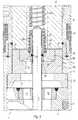
- Fig. 2 shows an axial excerpt Sectional view of a first embodiment of the embodiment of the invention Fuel injector 1. It will be enlarged Representation only those components listed in Regarding the invention are essential.
- the other components can be designed with a known fuel injector 1, in particular with the 1, fuel injector 1, be identical. Elements already described are included matching reference numerals so that there is a repetitive description is unnecessary.
- the one-piece anchor 20 shown in FIG. 1 is subdivided according to the invention in a first larger anchor part 20a and a second smaller anchor part 20b.
- the smaller one Anchor part 20b is in a central recess 28 of the arranged larger anchor part 20a.
- the larger anchor part 20a is replaced by a first stronger return spring 23a acts, the smaller anchor part 20b by a second weaker return spring 23b.
- the return spring 23a supports on the support flange 21 of a z.
- a flange 36 which is non-positively with the valve needle 3 is welded, serves as the lower Anchor stop, which intercepts the larger anchor part 20a, after it has detached from the inner pole 12.
- This effect can be caused by a slight wedge End faces 31 and 35 of the armature 20 are reinforced.
- the impact effect of a two-part anchor 20 is also improved over a one-piece anchor 20. This will on the one hand due to the reduced mass of each of the two Anchor parts 20a and 20b reached because of a smaller anchor mass bounces less.
- suitable Choice of the mass ratio of the anchor parts 20a and 20b achieve that the smaller armature part 20b from the inner pole 12th drops that it has fallen off and has already fallen from the flange 36 serving as the lower anchor stop rebounding anchor part 20a and the opposite impulses almost canceled be what an undesirable further momentary opening of the fuel injector 1 by the bouncing larger Anchor part 20a prevented.
- the flange 36 with the valve needle 3 is another briefly opening the fuel injector 1 prevented because the anchor part 20a in the closing direction on the Flange 36 hits and the pressure on the valve closing body 4 increased rather than decreased.
- FIG. 3 shows an axial excerpt Sectional view of a second embodiment of the embodiment of the invention Fuel injector 1. Elements already described are provided with the same reference numerals, so that a repetitive description is not necessary.
- the fuel injection valve 1 here one between the larger anchor part 20a and Support flange 21 located Vorhubspalt 30, the one Pre-acceleration of the two armature parts 20a, 20b enables.
- the anchor part 20a strikes the Support flange 21 already has a pulse in the stroke direction
- the over the support flange 21 on the valve needle 3rd is transmitted and has a positive impact on the opening times of the Fuel injector 1 affects.
- the lower anchor stop which is in the first Embodiment designed as a flange 36 and fixed with the valve needle 3 is connected, is in the second Embodiment designed and located as a ring 37 upstream of the nozzle body 2.
- the position fixed to the housing of the ring 37 is even more advantageous than that with the Valve needle 3 connected flange 36, since the valve needle 3rd now free when bouncing the larger anchor part 20a can swing through and no more impulse on this can be transferred.
- FIG 4 shows an axial section through an armature 20 a third embodiment of an inventive Fuel injector 1.
- the larger first anchor part 20a becomes ring-shaped from the smaller second anchor part 20b enclosed.
- the first anchor part 20a thereby contributes this embodiment inside and the second anchor part 20b on the outside against the inner pole 12.
- the invention is not shown on the Embodiments limited and also with a variety other designs of fuel injectors realizable.
- the second Return spring 23b also on the inner pole 12 or on one Support the housing component.
Claims (12)
- Injecteur de carburant (1) pour des installations d'injection de carburant de moteurs à combustion interne, notamment pour injecter directement du carburant dans la chambre de combustion d'un moteur à combustion interne, comprenant une bobine électromagnétique (10), un induit (20) sollicité par la bobine électromagnétique (10) dans le sens de la fermeture par un ressort de rappel (23) et une aiguille d'injecteur (3) reliée par une liaison de force à l'induit (20) pour actionner un organe d'obturation de soupape (4) formant un siège d'étanchéité avec une surface de siège de soupape (6),
l'induit (20) étant sollicité en outre par un second ressort de rappel (23b) et l'induit (20) étant subdivisé en une première partie d'induit (20) et une seconde partie d'induit (20b), la première partie d'induit (20a) étant sollicitée dans la direction de fermeture par le premier ressort de rappel (23a) alors que la seconde partie d'induit (20b) est sollicitée dans le sens de la fermeture par le second ressort de rappel (23b), dont les forces de rappel des ressorts (23a, 23b) sont différentes,
caractérisé en ce que
les deux parties d'induit (20a, 20b) sont associées l'une par rapport à l'autre,
en position de repos de l'injecteur de carburant (1), la seconde partie d'induit (20b) est appliquée par la mise en oeuvre du second ressort de rappel (23b) contre la première partie d'induit (20a). - Injecteur de carburant selon la revendication 1.
caractérisé en ce que
la première partie d'induit (20a) comporte une cavité centrale (28) guidant la seconde partie d'induit (20b). - Injecteur de carburant selon la revendication 2,
caractérisé en ce que
la première partie d'induit (20a) est reliée par une liaison de force avec une bride d'appui (21) reliée solidairement à l'aiguille d'injecteur (3). - Injecteur de carburant selon la revendication 3,
caractérisé en ce que
la bride d'appui (21) est réalisée sur une pièce de fixation (34) en forme de manchon et l'aiguille d'injecteur (3) traverse une cavité centrale de la surface d'appui (21). - Injecteur de carburant selon les revendications 3 ou 4,
caractérisé en ce que
la première partie d'induit (20a) est sollicitée par le premier ressort de rappel (23a) par l'intermédiaire de la surface d'appui (21) contre l'aiguille d'injecteur (3). - Injecteur de carburant selon l'une des revendications 3 à 5,
caractérisé en ce que
la seconde partie d'induit (20b) est reliée par le second ressort de rappel (23b) à la bride d'appui (21) par une liaison par la force. - Injecteur de carburant selon l'une des revendications précédentes,
caractérisé en ce que
les deux parties d'induit (20a, 20b) se rapprochent en commun d'un pôle intérieur (12) dans la direction opposée à la direction de fermeture lorsque la bobine électromagnétique (10) est excitée. - Injecteur de carburant selon la revendication 7,
caractérisé en ce que
lors de la coupure de la bobine électromagnétique (10) la première partie d'induit (20a) se détache du pôle intérieur (12) sous l'effet de la force de rappel exercée par le premier ressort de rappel (23a) et revient en position de repos indépendamment de la seconde partie d'induit (20b). - Injecteur de carburant selon la revendication 8,
caractérisé en ce que
la seconde partie d'induit (20b) revient en position de repos sous l'effet du second ressort de rappel (23b) lorsque le champ magnétique continue de diminuer. - Injecteur de carburant selon l'une des revendications 7 à 9,
caractérisé en ce qu'
au moins la première partie d'induit (20a) possède une face frontale (31) tournée vers le pôle intérieur (12), cette face ayant une conicité. - Injecteur de carburant selon la revendication 10,
caractérisé en ce que
la première partie d'induit (20a) présente une face frontale conique (31), la seconde partie d'induit (20b) présente une face frontale (35) tournée vers le pôle intérieur (12), cette face ayant également une forme conique et la conicité de la face frontale (31) de la première partie d'induit (20a) est supérieure à la conicité de la face frontale (35) de la seconde partie d'induit (20b). - Injecteur de carburant selon l'une des revendications 3 à 6,
caractérisé par
un intervalle de course d'avance (30) prévu entre la bride d'appui (21) et la première partie d'induit (20a), cet intervalle permettant une pré-accélération de la première partie d'induit (20a) avant que celle-ci n'agisse sur l'aiguille d'injecteur (3) par l'intermédiaire de la bride d'appui (21).
Applications Claiming Priority (3)
| Application Number | Priority Date | Filing Date | Title |
|---|---|---|---|
| DE19948238 | 1999-10-07 | ||
| DE19948238A DE19948238A1 (de) | 1999-10-07 | 1999-10-07 | Brennstoffeinspritzventil |
| PCT/DE2000/003496 WO2001025614A1 (fr) | 1999-10-07 | 2000-10-05 | Soupape d'injection de carburant |
Publications (2)
| Publication Number | Publication Date |
|---|---|
| EP1137877A1 EP1137877A1 (fr) | 2001-10-04 |
| EP1137877B1 true EP1137877B1 (fr) | 2004-08-18 |
Family
ID=7924767
Family Applications (1)
| Application Number | Title | Priority Date | Filing Date |
|---|---|---|---|
| EP00979405A Expired - Lifetime EP1137877B1 (fr) | 1999-10-07 | 2000-10-05 | Soupape d'injection de carburant |
Country Status (8)
| Country | Link |
|---|---|
| US (1) | US6510841B1 (fr) |
| EP (1) | EP1137877B1 (fr) |
| JP (1) | JP4603749B2 (fr) |
| BR (1) | BR0007097A (fr) |
| CZ (1) | CZ20011996A3 (fr) |
| DE (2) | DE19948238A1 (fr) |
| ES (1) | ES2226945T3 (fr) |
| WO (1) | WO2001025614A1 (fr) |
Cited By (1)
| Publication number | Priority date | Publication date | Assignee | Title |
|---|---|---|---|---|
| EP2896813A1 (fr) | 2014-01-17 | 2015-07-22 | Continental Automotive GmbH | Soupape d'injection de carburant pour moteurs à combustion interne |
Families Citing this family (65)
| Publication number | Priority date | Publication date | Assignee | Title |
|---|---|---|---|---|
| DE19957172A1 (de) * | 1999-11-27 | 2001-08-09 | Bosch Gmbh Robert | Brennstoffeinspritzventil |
| DE10039083A1 (de) | 2000-08-10 | 2002-02-21 | Bosch Gmbh Robert | Brennstoffeinspritzventil |
| DE10123278C1 (de) * | 2001-05-10 | 2002-06-13 | Univ Hamburg | Vorrichtung zur Beatmung mit einem Endotrachealtubus |
| DE10124743A1 (de) * | 2001-05-21 | 2002-11-28 | Bosch Gmbh Robert | Brennstoffeinspritzventil |
| DE10124747A1 (de) * | 2001-05-21 | 2002-11-28 | Bosch Gmbh Robert | Brennstoffeinspritzventil |
| DE10136808A1 (de) | 2001-07-27 | 2003-02-13 | Bosch Gmbh Robert | Brennstoffeinspritzventil |
| DE10256661A1 (de) * | 2002-12-04 | 2004-06-17 | Robert Bosch Gmbh | Brennstoffeinspritzventil |
| DE10319384A1 (de) * | 2003-04-30 | 2004-11-18 | Universität Hamburg | Vorrichtung zur Beatmung mit einem doppellumigen Endotrachealtubus |
| JP4045209B2 (ja) * | 2003-06-20 | 2008-02-13 | 株式会社日立製作所 | 電磁式燃料噴射弁 |
| DE10332812B4 (de) * | 2003-07-18 | 2014-05-15 | Robert Bosch Gmbh | Brennstoffeinspritzventil |
| DE10345967B4 (de) * | 2003-10-02 | 2014-02-27 | Robert Bosch Gmbh | Brennstoffeinspritzventil |
| US7156368B2 (en) | 2004-04-14 | 2007-01-02 | Cummins Inc. | Solenoid actuated flow controller valve |
| US20060138374A1 (en) * | 2004-04-14 | 2006-06-29 | Lucas Michael A | Solenoid actuated flow control valve including adjustable spacer |
| DE102004024533A1 (de) * | 2004-05-18 | 2005-12-15 | Robert Bosch Gmbh | Brennstoffeinspritzventil |
| JP4239942B2 (ja) * | 2004-09-22 | 2009-03-18 | 株式会社デンソー | 燃料噴射弁 |
| JP2006097659A (ja) * | 2004-09-30 | 2006-04-13 | Nippon Soken Inc | 燃料噴射弁 |
| JP2006258074A (ja) * | 2005-03-18 | 2006-09-28 | Hitachi Ltd | 燃料噴射弁 |
| EP1801409B1 (fr) * | 2005-12-23 | 2008-08-27 | Delphi Technologies, Inc. | Injecteur de carburant |
| US8166953B2 (en) * | 2006-02-06 | 2012-05-01 | Orbital Australia Pty Limited | Fuel injection apparatus |
| US7741941B2 (en) * | 2006-11-30 | 2010-06-22 | Honeywell International Inc. | Dual armature solenoid valve assembly |
| JP5072745B2 (ja) * | 2008-07-07 | 2012-11-14 | 株式会社ケーヒン | 電磁式燃料噴射弁及びその製造方法 |
| EP2236807B1 (fr) | 2009-03-23 | 2016-05-11 | Continental Automotive GmbH | Injecteur de fluide |
| EP2241743B1 (fr) * | 2009-04-14 | 2014-07-02 | Continental Automotive GmbH | Ensemble de soupape pour soupape d'injection et soupape d'injection |
| JP5019137B2 (ja) * | 2009-09-04 | 2012-09-05 | 株式会社デンソー | 電磁駆動弁及びこれを用いた燃料噴射装置 |
| EP2333297B1 (fr) * | 2009-12-11 | 2013-03-20 | Continental Automotive GmbH | Ensemble de soupape pour soupape d'injection et soupape d'injection |
| US8215573B2 (en) * | 2010-05-14 | 2012-07-10 | Continental Automotive Systems Us, Inc. | Automotive gasoline solenoid double pole direct injector |
| US8453951B2 (en) * | 2010-09-22 | 2013-06-04 | Delphi Technologies, Inc. | Fuel injector |
| EP2436910B1 (fr) * | 2010-10-01 | 2017-05-03 | Continental Automotive GmbH | Ensemble de soupape pour soupape d'injection et soupape d'injection |
| JP5835421B2 (ja) * | 2010-10-05 | 2015-12-24 | 株式会社デンソー | 燃料噴射弁 |
| EP2444651B1 (fr) * | 2010-10-19 | 2013-07-10 | Continental Automotive GmbH | Ensemble de soupape pour soupape d'injection et soupape d'injection |
| JP5537472B2 (ja) * | 2011-03-10 | 2014-07-02 | 日立オートモティブシステムズ株式会社 | 燃料噴射装置 |
| EP2511515A1 (fr) * | 2011-04-14 | 2012-10-17 | Continental Automotive GmbH | Injecteur pour injection de fluides |
| US8689772B2 (en) | 2011-05-19 | 2014-04-08 | Caterpillar Inc. | Fuel injector with telescoping armature overtravel feature |
| JP5822269B2 (ja) | 2011-11-11 | 2015-11-24 | 株式会社ケーヒン | 電磁式燃料噴射弁 |
| JP5982210B2 (ja) | 2012-07-27 | 2016-08-31 | 日立オートモティブシステムズ株式会社 | 電磁式燃料噴射弁 |
| DE102012215448B3 (de) | 2012-08-31 | 2013-12-12 | Continental Automotive Gmbh | Injektor zur Krafteinspritzung in eine Brennkraftmaschine |
| JP6186126B2 (ja) | 2013-01-24 | 2017-08-23 | 日立オートモティブシステムズ株式会社 | 燃料噴射装置 |
| CN107605635B (zh) * | 2013-07-29 | 2022-11-18 | 日立安斯泰莫株式会社 | 燃料喷射装置的驱动装置 |
| EP2860386A1 (fr) * | 2013-10-10 | 2015-04-15 | Continental Automotive GmbH | Injecteur pour moteur à combustion |
| JP2015121188A (ja) * | 2013-12-25 | 2015-07-02 | 日立オートモティブシステムズ株式会社 | 燃料噴射弁 |
| US9453456B2 (en) * | 2014-01-21 | 2016-09-27 | Dresser-Rand Company | Electronic pre-chamber injector |
| EP2949917B1 (fr) * | 2014-05-27 | 2017-01-04 | Continental Automotive GmbH | Injecteur à carburant |
| DE102014220877B3 (de) * | 2014-10-15 | 2015-12-03 | Continental Automotive Gmbh | Kraftstoffeinspritzventil |
| KR101652586B1 (ko) * | 2014-10-22 | 2016-08-30 | 주식회사 현대케피코 | 연료 인젝터 |
| JP6277941B2 (ja) | 2014-11-05 | 2018-02-14 | 株式会社デンソー | 燃料噴射装置 |
| DE102015214171A1 (de) * | 2015-07-27 | 2017-02-02 | Robert Bosch Gmbh | Ventil zum Zumessen eines Fluids |
| JP6175475B2 (ja) | 2015-11-20 | 2017-08-02 | 株式会社ケーヒン | 電磁式燃料噴射弁 |
| JP6613973B2 (ja) * | 2016-03-10 | 2019-12-04 | 株式会社デンソー | 燃料噴射装置 |
| EP3260695B8 (fr) * | 2016-06-24 | 2019-07-17 | CPT Group GmbH | Ensemble de soupape pour soupape d'injection et soupape d'injection |
| DE112017003727T5 (de) * | 2016-08-26 | 2019-05-02 | Hitachi Automotive Systems, Ltd. | Kraftstoffeinspritzventil |
| DE102016225776A1 (de) * | 2016-12-21 | 2018-06-21 | Robert Bosch Gmbh | Ventil zum Zumessen eines Fluids |
| JP2018105271A (ja) * | 2016-12-28 | 2018-07-05 | 日立オートモティブシステムズ株式会社 | 燃料噴射弁 |
| WO2018150834A1 (fr) * | 2017-02-17 | 2018-08-23 | 日立オートモティブシステムズ株式会社 | Dispositif de commande d'injection de carburant et procédé de commande d'injection de carburant |
| JP6677194B2 (ja) * | 2017-03-03 | 2020-04-08 | 株式会社デンソー | 燃料噴射弁 |
| JP6364524B2 (ja) * | 2017-04-27 | 2018-07-25 | 日立オートモティブシステムズ株式会社 | 電磁式燃料噴射弁 |
| DE102017207845A1 (de) * | 2017-05-10 | 2018-11-15 | Robert Bosch Gmbh | Ventil zum Zumessen eines Fluids |
| JP6782856B2 (ja) * | 2017-10-13 | 2020-11-11 | 日立オートモティブシステムズ株式会社 | 燃料噴射弁 |
| JP6913816B2 (ja) * | 2018-02-23 | 2021-08-04 | 日立Astemo株式会社 | 燃料噴射弁及びその組立方法 |
| JP6753432B2 (ja) * | 2018-05-08 | 2020-09-09 | 株式会社デンソー | 燃料噴射装置 |
| WO2020022099A1 (fr) * | 2018-07-24 | 2020-01-30 | 日立オートモティブシステムズ株式会社 | Soupape d'injection de carburant |
| JP7338155B2 (ja) * | 2019-01-08 | 2023-09-05 | 株式会社デンソー | 燃料噴射弁 |
| JP6762393B2 (ja) * | 2019-03-18 | 2020-09-30 | 日立オートモティブシステムズ株式会社 | 燃料噴射装置 |
| EP3821985B1 (fr) * | 2019-11-18 | 2023-08-23 | Reinhold Schulte | Unité de soupape de pulvérisation agricole, dispositif de pulvérisation agricole, dispositif d'épandage agricole et procédé de fonctionnement d'une unité de soupape de pulvérisation agricole |
| EP4348031A1 (fr) * | 2021-05-28 | 2024-04-10 | Stanadyne LLC | Injecteur de carburant |
| KR102638111B1 (ko) * | 2021-07-09 | 2024-02-19 | 주식회사 현대케피코 | 작동시 니들의 거동을 방지할 수 있는 연료 인젝터 |
Family Cites Families (13)
| Publication number | Priority date | Publication date | Assignee | Title |
|---|---|---|---|---|
| US4508091A (en) * | 1979-10-26 | 1985-04-02 | Colt Industries Operating Corp | Fuel metering apparatus with multi-stage fuel metering valve assembly |
| US4311280A (en) * | 1980-07-21 | 1982-01-19 | General Motors Corporation | Electromagnetic fuel injector with adjustable armature spring |
| DE3314899A1 (de) | 1983-04-25 | 1984-10-25 | Mesenich, Gerhard, Dipl.-Ing., 4630 Bochum | Federanordnung mit zusatzmasse zur verbesserung des dynamischen verhaltens von elektromagnetsystemen |
| US5118077A (en) * | 1991-08-09 | 1992-06-02 | Borg-Warner Automotive Electronic & Mechanical Systems Corporation | Pulse width modulated solenoid valve for variable displacement control |
| FR2722538B1 (fr) | 1994-07-12 | 1996-09-20 | Magneti Marelli France | Injecteur de carburant "bi-jet" a noyaux et entrefers en parallele pour moteur a combustion interne alimente par injection |
| AT1622U1 (de) * | 1995-02-28 | 1997-08-25 | Avl Verbrennungskraft Messtech | Einspritzsystem mit einem einspritzventil für eine selbstzündende brennkraftmaschine |
| AUPN391295A0 (en) | 1995-06-30 | 1995-07-27 | Orbital Engine Company (Australia) Proprietary Limited | Fuel injection apparatus |
| US5717372A (en) * | 1995-08-14 | 1998-02-10 | Caterpillar Inc. | Dual armature solenoid |
| DE19650865A1 (de) * | 1996-12-07 | 1998-06-10 | Bosch Gmbh Robert | Magnetventil |
| DE19708104A1 (de) * | 1997-02-28 | 1998-09-03 | Bosch Gmbh Robert | Magnetventil |
| KR20010031761A (ko) | 1997-11-03 | 2001-04-16 | 디이젤 엔진 리타더스, 인코포레이티드 | 캐스케이드 전자 전기자 |
| DE19756103A1 (de) * | 1997-12-17 | 1999-06-24 | Bosch Gmbh Robert | Brennstoffeinspritzventil |
| US6047718A (en) * | 1999-04-01 | 2000-04-11 | Emersonelectric Co. | Solenoid valve having coaxial armatures in a single coil design |
-
1999
- 1999-10-07 DE DE19948238A patent/DE19948238A1/de not_active Withdrawn
-
2000
- 2000-10-05 US US09/857,239 patent/US6510841B1/en not_active Expired - Lifetime
- 2000-10-05 EP EP00979405A patent/EP1137877B1/fr not_active Expired - Lifetime
- 2000-10-05 DE DE50007470T patent/DE50007470D1/de not_active Expired - Lifetime
- 2000-10-05 CZ CZ20011996A patent/CZ20011996A3/cs unknown
- 2000-10-05 ES ES00979405T patent/ES2226945T3/es not_active Expired - Lifetime
- 2000-10-05 JP JP2001528322A patent/JP4603749B2/ja not_active Expired - Fee Related
- 2000-10-05 WO PCT/DE2000/003496 patent/WO2001025614A1/fr not_active Application Discontinuation
- 2000-10-05 BR BR0007097-1A patent/BR0007097A/pt not_active IP Right Cessation
Cited By (4)
| Publication number | Priority date | Publication date | Assignee | Title |
|---|---|---|---|---|
| EP2896813A1 (fr) | 2014-01-17 | 2015-07-22 | Continental Automotive GmbH | Soupape d'injection de carburant pour moteurs à combustion interne |
| KR20150086191A (ko) * | 2014-01-17 | 2015-07-27 | 콘티넨탈 오토모티브 게엠베하 | 내연 기관을 위한 연료 분사 밸브 |
| US9382885B2 (en) | 2014-01-17 | 2016-07-05 | Continental Automotive Gmbh | Fuel injection valve for an internal combustion engine |
| KR102274061B1 (ko) | 2014-01-17 | 2021-07-07 | 콘티넨탈 오토모티브 게엠베하 | 내연 기관을 위한 연료 분사 밸브 |
Also Published As
| Publication number | Publication date |
|---|---|
| US6510841B1 (en) | 2003-01-28 |
| WO2001025614A1 (fr) | 2001-04-12 |
| WO2001025614A8 (fr) | 2001-09-20 |
| DE19948238A1 (de) | 2001-04-19 |
| EP1137877A1 (fr) | 2001-10-04 |
| CZ20011996A3 (cs) | 2002-05-15 |
| DE50007470D1 (de) | 2004-09-23 |
| JP2003511604A (ja) | 2003-03-25 |
| ES2226945T3 (es) | 2005-04-01 |
| JP4603749B2 (ja) | 2010-12-22 |
| BR0007097A (pt) | 2001-10-16 |
Similar Documents
| Publication | Publication Date | Title |
|---|---|---|
| EP1137877B1 (fr) | Soupape d'injection de carburant | |
| EP1012469B1 (fr) | Soupape d'injection de carburant | |
| EP1415083B1 (fr) | Soupape d'injection de carburant | |
| EP1135599B1 (fr) | Soupape d'injection de carburant | |
| EP1255929B1 (fr) | Soupape d'injection de carburant et son procede de commande | |
| EP1151190B1 (fr) | Soupape d'injection de carburant | |
| EP0459999B1 (fr) | Soupape injectrice electromagnetique a haute pression | |
| EP1068440B1 (fr) | Vanne electromagnetique | |
| EP0683862B1 (fr) | Soupape a commande electromagnetique | |
| DE19708104A1 (de) | Magnetventil | |
| EP0861371A1 (fr) | Soupape d'injection de carburant avec bougie d'allumage integree | |
| EP1966483B1 (fr) | Soupape a actionnement electromagnetique | |
| DE3314899A1 (de) | Federanordnung mit zusatzmasse zur verbesserung des dynamischen verhaltens von elektromagnetsystemen | |
| EP0988447A1 (fr) | Soupape d'injection de carburant | |
| EP1165960B1 (fr) | Soupape d'injection de carburant | |
| DE102014226367A1 (de) | Brennstoffeinspritzventil | |
| DE10060290A1 (de) | Brennstoffeinspritzventil | |
| DE102012201413A1 (de) | Magnetventil für einen Kraftstoffinjektor | |
| DE10063261B4 (de) | Brennstoffeinspritzventil | |
| DE10005015B4 (de) | Verfahren zum Betreiben eines Brennstoffeinspritzventils | |
| DE10039080A1 (de) | Brennstoffeinspritzventil und Verfahren zum Betrieb eines Brennstoffeinspritzventils | |
| DE10005013A1 (de) | Brennstoffeinspritzventil |
Legal Events
| Date | Code | Title | Description |
|---|---|---|---|
| PUAI | Public reference made under article 153(3) epc to a published international application that has entered the european phase |
Free format text: ORIGINAL CODE: 0009012 |
|
| AK | Designated contracting states |
Kind code of ref document: A1 Designated state(s): AT BE CH CY DE DK ES FI FR GB GR IE IT LI LU MC NL PT SE |
|
| 17P | Request for examination filed |
Effective date: 20011012 |
|
| 17Q | First examination report despatched |
Effective date: 20020212 |
|
| GRAP | Despatch of communication of intention to grant a patent |
Free format text: ORIGINAL CODE: EPIDOSNIGR1 |
|
| GRAS | Grant fee paid |
Free format text: ORIGINAL CODE: EPIDOSNIGR3 |
|
| GRAA | (expected) grant |
Free format text: ORIGINAL CODE: 0009210 |
|
| AK | Designated contracting states |
Kind code of ref document: B1 Designated state(s): DE ES FR GB IT |
|
| REG | Reference to a national code |
Ref country code: GB Ref legal event code: FG4D Free format text: NOT ENGLISH |
|
| REG | Reference to a national code |
Ref country code: IE Ref legal event code: FG4D Free format text: GERMAN |
|
| REF | Corresponds to: |
Ref document number: 50007470 Country of ref document: DE Date of ref document: 20040923 Kind code of ref document: P |
|
| GBT | Gb: translation of ep patent filed (gb section 77(6)(a)/1977) |
Effective date: 20050107 |
|
| REG | Reference to a national code |
Ref country code: IE Ref legal event code: FD4D |
|
| REG | Reference to a national code |
Ref country code: ES Ref legal event code: FG2A Ref document number: 2226945 Country of ref document: ES Kind code of ref document: T3 |
|
| ET | Fr: translation filed | ||
| PLBE | No opposition filed within time limit |
Free format text: ORIGINAL CODE: 0009261 |
|
| STAA | Information on the status of an ep patent application or granted ep patent |
Free format text: STATUS: NO OPPOSITION FILED WITHIN TIME LIMIT |
|
| 26N | No opposition filed |
Effective date: 20050519 |
|
| PGFP | Annual fee paid to national office [announced via postgrant information from national office to epo] |
Ref country code: GB Payment date: 20050923 Year of fee payment: 6 |
|
| PGFP | Annual fee paid to national office [announced via postgrant information from national office to epo] |
Ref country code: ES Payment date: 20051014 Year of fee payment: 6 |
|
| PGFP | Annual fee paid to national office [announced via postgrant information from national office to epo] |
Ref country code: FR Payment date: 20051019 Year of fee payment: 6 |
|
| PGFP | Annual fee paid to national office [announced via postgrant information from national office to epo] |
Ref country code: IT Payment date: 20061031 Year of fee payment: 7 |
|
| GBPC | Gb: european patent ceased through non-payment of renewal fee |
Effective date: 20061005 |
|
| REG | Reference to a national code |
Ref country code: FR Ref legal event code: ST Effective date: 20070629 |
|
| PG25 | Lapsed in a contracting state [announced via postgrant information from national office to epo] |
Ref country code: GB Free format text: LAPSE BECAUSE OF NON-PAYMENT OF DUE FEES Effective date: 20061005 |
|
| REG | Reference to a national code |
Ref country code: ES Ref legal event code: FD2A Effective date: 20061006 |
|
| PG25 | Lapsed in a contracting state [announced via postgrant information from national office to epo] |
Ref country code: FR Free format text: LAPSE BECAUSE OF NON-PAYMENT OF DUE FEES Effective date: 20061031 Ref country code: ES Free format text: LAPSE BECAUSE OF NON-PAYMENT OF DUE FEES Effective date: 20061006 |
|
| PG25 | Lapsed in a contracting state [announced via postgrant information from national office to epo] |
Ref country code: IT Free format text: LAPSE BECAUSE OF NON-PAYMENT OF DUE FEES Effective date: 20071005 |
|
| PGFP | Annual fee paid to national office [announced via postgrant information from national office to epo] |
Ref country code: DE Payment date: 20151215 Year of fee payment: 16 |
|
| REG | Reference to a national code |
Ref country code: DE Ref legal event code: R119 Ref document number: 50007470 Country of ref document: DE |
|
| PG25 | Lapsed in a contracting state [announced via postgrant information from national office to epo] |
Ref country code: DE Free format text: LAPSE BECAUSE OF NON-PAYMENT OF DUE FEES Effective date: 20170503 |