EP0459999B1 - Soupape injectrice electromagnetique a haute pression - Google Patents
Soupape injectrice electromagnetique a haute pression Download PDFInfo
- Publication number
- EP0459999B1 EP0459999B1 EP90902618A EP90902618A EP0459999B1 EP 0459999 B1 EP0459999 B1 EP 0459999B1 EP 90902618 A EP90902618 A EP 90902618A EP 90902618 A EP90902618 A EP 90902618A EP 0459999 B1 EP0459999 B1 EP 0459999B1
- Authority
- EP
- European Patent Office
- Prior art keywords
- valve
- armature
- injection
- injection valve
- needle
- Prior art date
- Legal status (The legal status is an assumption and is not a legal conclusion. Google has not performed a legal analysis and makes no representation as to the accuracy of the status listed.)
- Expired - Lifetime
Links
Images

Classifications
-
- F—MECHANICAL ENGINEERING; LIGHTING; HEATING; WEAPONS; BLASTING
- F02—COMBUSTION ENGINES; HOT-GAS OR COMBUSTION-PRODUCT ENGINE PLANTS
- F02M—SUPPLYING COMBUSTION ENGINES IN GENERAL WITH COMBUSTIBLE MIXTURES OR CONSTITUENTS THEREOF
- F02M51/00—Fuel-injection apparatus characterised by being operated electrically
- F02M51/06—Injectors peculiar thereto with means directly operating the valve needle
- F02M51/061—Injectors peculiar thereto with means directly operating the valve needle using electromagnetic operating means
- F02M51/0614—Injectors peculiar thereto with means directly operating the valve needle using electromagnetic operating means characterised by arrangement of electromagnets or fixed armature
- F02M51/0617—Injectors peculiar thereto with means directly operating the valve needle using electromagnetic operating means characterised by arrangement of electromagnets or fixed armature having two or more electromagnets
- F02M51/0621—Injectors peculiar thereto with means directly operating the valve needle using electromagnetic operating means characterised by arrangement of electromagnets or fixed armature having two or more electromagnets acting on one mobile armature
-
- F—MECHANICAL ENGINEERING; LIGHTING; HEATING; WEAPONS; BLASTING
- F02—COMBUSTION ENGINES; HOT-GAS OR COMBUSTION-PRODUCT ENGINE PLANTS
- F02M—SUPPLYING COMBUSTION ENGINES IN GENERAL WITH COMBUSTIBLE MIXTURES OR CONSTITUENTS THEREOF
- F02M45/00—Fuel-injection apparatus characterised by having a cyclic delivery of specific time/pressure or time/quantity relationship
- F02M45/02—Fuel-injection apparatus characterised by having a cyclic delivery of specific time/pressure or time/quantity relationship with each cyclic delivery being separated into two or more parts
- F02M45/04—Fuel-injection apparatus characterised by having a cyclic delivery of specific time/pressure or time/quantity relationship with each cyclic delivery being separated into two or more parts with a small initial part, e.g. initial part for partial load and initial and main part for full load
- F02M45/08—Injectors peculiar thereto
-
- F—MECHANICAL ENGINEERING; LIGHTING; HEATING; WEAPONS; BLASTING
- F02—COMBUSTION ENGINES; HOT-GAS OR COMBUSTION-PRODUCT ENGINE PLANTS
- F02M—SUPPLYING COMBUSTION ENGINES IN GENERAL WITH COMBUSTIBLE MIXTURES OR CONSTITUENTS THEREOF
- F02M51/00—Fuel-injection apparatus characterised by being operated electrically
- F02M51/06—Injectors peculiar thereto with means directly operating the valve needle
- F02M51/061—Injectors peculiar thereto with means directly operating the valve needle using electromagnetic operating means
- F02M51/0614—Injectors peculiar thereto with means directly operating the valve needle using electromagnetic operating means characterised by arrangement of electromagnets or fixed armature
-
- F—MECHANICAL ENGINEERING; LIGHTING; HEATING; WEAPONS; BLASTING
- F02—COMBUSTION ENGINES; HOT-GAS OR COMBUSTION-PRODUCT ENGINE PLANTS
- F02M—SUPPLYING COMBUSTION ENGINES IN GENERAL WITH COMBUSTIBLE MIXTURES OR CONSTITUENTS THEREOF
- F02M51/00—Fuel-injection apparatus characterised by being operated electrically
- F02M51/06—Injectors peculiar thereto with means directly operating the valve needle
- F02M51/061—Injectors peculiar thereto with means directly operating the valve needle using electromagnetic operating means
- F02M51/0625—Injectors peculiar thereto with means directly operating the valve needle using electromagnetic operating means characterised by arrangement of mobile armatures
- F02M51/0664—Injectors peculiar thereto with means directly operating the valve needle using electromagnetic operating means characterised by arrangement of mobile armatures having a cylindrically or partly cylindrically shaped armature, e.g. entering the winding; having a plate-shaped or undulated armature entering the winding
- F02M51/0671—Injectors peculiar thereto with means directly operating the valve needle using electromagnetic operating means characterised by arrangement of mobile armatures having a cylindrically or partly cylindrically shaped armature, e.g. entering the winding; having a plate-shaped or undulated armature entering the winding the armature having an elongated valve body attached thereto
-
- F—MECHANICAL ENGINEERING; LIGHTING; HEATING; WEAPONS; BLASTING
- F02—COMBUSTION ENGINES; HOT-GAS OR COMBUSTION-PRODUCT ENGINE PLANTS
- F02M—SUPPLYING COMBUSTION ENGINES IN GENERAL WITH COMBUSTIBLE MIXTURES OR CONSTITUENTS THEREOF
- F02M51/00—Fuel-injection apparatus characterised by being operated electrically
- F02M51/06—Injectors peculiar thereto with means directly operating the valve needle
- F02M51/061—Injectors peculiar thereto with means directly operating the valve needle using electromagnetic operating means
- F02M51/0689—Injectors peculiar thereto with means directly operating the valve needle using electromagnetic operating means and permanent magnets
- F02M51/0692—Injectors peculiar thereto with means directly operating the valve needle using electromagnetic operating means and permanent magnets as valve or armature return means
-
- F—MECHANICAL ENGINEERING; LIGHTING; HEATING; WEAPONS; BLASTING
- F02—COMBUSTION ENGINES; HOT-GAS OR COMBUSTION-PRODUCT ENGINE PLANTS
- F02M—SUPPLYING COMBUSTION ENGINES IN GENERAL WITH COMBUSTIBLE MIXTURES OR CONSTITUENTS THEREOF
- F02M61/00—Fuel-injectors not provided for in groups F02M39/00 - F02M57/00 or F02M67/00
- F02M61/16—Details not provided for in, or of interest apart from, the apparatus of groups F02M61/02 - F02M61/14
- F02M61/161—Means for adjusting injection-valve lift
-
- F—MECHANICAL ENGINEERING; LIGHTING; HEATING; WEAPONS; BLASTING
- F02—COMBUSTION ENGINES; HOT-GAS OR COMBUSTION-PRODUCT ENGINE PLANTS
- F02M—SUPPLYING COMBUSTION ENGINES IN GENERAL WITH COMBUSTIBLE MIXTURES OR CONSTITUENTS THEREOF
- F02M61/00—Fuel-injectors not provided for in groups F02M39/00 - F02M57/00 or F02M67/00
- F02M61/16—Details not provided for in, or of interest apart from, the apparatus of groups F02M61/02 - F02M61/14
- F02M61/20—Closing valves mechanically, e.g. arrangements of springs or weights or permanent magnets; Damping of valve lift
-
- H—ELECTRICITY
- H01—ELECTRIC ELEMENTS
- H01F—MAGNETS; INDUCTANCES; TRANSFORMERS; SELECTION OF MATERIALS FOR THEIR MAGNETIC PROPERTIES
- H01F7/00—Magnets
- H01F7/06—Electromagnets; Actuators including electromagnets
- H01F7/08—Electromagnets; Actuators including electromagnets with armatures
- H01F7/16—Rectilinearly-movable armatures
- H01F7/1607—Armatures entering the winding
- H01F7/1615—Armatures or stationary parts of magnetic circuit having permanent magnet
-
- F—MECHANICAL ENGINEERING; LIGHTING; HEATING; WEAPONS; BLASTING
- F02—COMBUSTION ENGINES; HOT-GAS OR COMBUSTION-PRODUCT ENGINE PLANTS
- F02B—INTERNAL-COMBUSTION PISTON ENGINES; COMBUSTION ENGINES IN GENERAL
- F02B2275/00—Other engines, components or details, not provided for in other groups of this subclass
- F02B2275/14—Direct injection into combustion chamber
-
- F—MECHANICAL ENGINEERING; LIGHTING; HEATING; WEAPONS; BLASTING
- F02—COMBUSTION ENGINES; HOT-GAS OR COMBUSTION-PRODUCT ENGINE PLANTS
- F02M—SUPPLYING COMBUSTION ENGINES IN GENERAL WITH COMBUSTIBLE MIXTURES OR CONSTITUENTS THEREOF
- F02M2200/00—Details of fuel-injection apparatus, not otherwise provided for
- F02M2200/30—Fuel-injection apparatus having mechanical parts, the movement of which is damped
- F02M2200/304—Fuel-injection apparatus having mechanical parts, the movement of which is damped using hydraulic means
-
- F—MECHANICAL ENGINEERING; LIGHTING; HEATING; WEAPONS; BLASTING
- F02—COMBUSTION ENGINES; HOT-GAS OR COMBUSTION-PRODUCT ENGINE PLANTS
- F02M—SUPPLYING COMBUSTION ENGINES IN GENERAL WITH COMBUSTIBLE MIXTURES OR CONSTITUENTS THEREOF
- F02M2200/00—Details of fuel-injection apparatus, not otherwise provided for
- F02M2200/30—Fuel-injection apparatus having mechanical parts, the movement of which is damped
- F02M2200/306—Fuel-injection apparatus having mechanical parts, the movement of which is damped using mechanical means
-
- H—ELECTRICITY
- H01—ELECTRIC ELEMENTS
- H01F—MAGNETS; INDUCTANCES; TRANSFORMERS; SELECTION OF MATERIALS FOR THEIR MAGNETIC PROPERTIES
- H01F7/00—Magnets
- H01F7/06—Electromagnets; Actuators including electromagnets
- H01F7/08—Electromagnets; Actuators including electromagnets with armatures
- H01F7/121—Guiding or setting position of armatures, e.g. retaining armatures in their end position
- H01F7/122—Guiding or setting position of armatures, e.g. retaining armatures in their end position by permanent magnets
-
- Y—GENERAL TAGGING OF NEW TECHNOLOGICAL DEVELOPMENTS; GENERAL TAGGING OF CROSS-SECTIONAL TECHNOLOGIES SPANNING OVER SEVERAL SECTIONS OF THE IPC; TECHNICAL SUBJECTS COVERED BY FORMER USPC CROSS-REFERENCE ART COLLECTIONS [XRACs] AND DIGESTS
- Y02—TECHNOLOGIES OR APPLICATIONS FOR MITIGATION OR ADAPTATION AGAINST CLIMATE CHANGE
- Y02T—CLIMATE CHANGE MITIGATION TECHNOLOGIES RELATED TO TRANSPORTATION
- Y02T10/00—Road transport of goods or passengers
- Y02T10/10—Internal combustion engine [ICE] based vehicles
- Y02T10/12—Improving ICE efficiencies
Definitions
- the invention relates to an electromagnetic high-pressure injection valve for injecting fuel into the combustion chamber of internal combustion engines.
- the injection valve is mainly used for small and medium-sized diesel engines with a displacement of 300 cm3 to 700 cm3 per cylinder.
- the typical flow rate of the valve is 10-25 mm3 / ms.
- the injection valve can be used up to a fuel pressure of approx. 1000 bar.
- the valve has a needle-shaped valve closing body which is connected to the armature of an electromagnet. Similar to the known low-pressure injection valves, the fuel supply to the injection nozzle is released when the armature is pulled up.
- the injection valve is supplied with fuel by a high-pressure piston pump mechanically driven by the engine.
- Purely mechanical injection systems are usually used for high-pressure injection.
- the fuel is compressed in a pump element at the start of the injection process and the pump energy is transmitted to the injection nozzle as a pressure wave.
- the injection nozzle is provided with a nozzle needle which is lifted off the valve seat by the fuel pressure against the force of a spring.
- the resetting force of the spring is between 400 and 2000 N depending on the opening pressure of the nozzle.
- the diameter of the injectors is usually approx. 2 mm. Due to the high restoring force and the relatively large mass of the nozzle needle, the valve seat is exposed to a strong impact when the valve is closed.
- Strong pressure waves are reflected between the pump and nozzle during and after the injection process.
- the amplitude of these waves can be up to several 100 bar.
- the pressure waves may touch the zero line, below which the vapor pressure of the fuel falls below. This leads to cavitation in the elements of the injection system and to the formation of cavities with strong shock loads.
- the reflected pressure waves can trigger the needle to open again. In this case, post-spraying is delayed by the duration of the pressure wave, in which the fuel is atomized only poorly and only partially participates in the combustion. Additional injection is created by the needle bouncing that is always present when the valve is closed.
- the pumping process in the mechanically operating injection systems is firmly coupled to a certain angle of rotation.
- the injection pump is subjected to a high shock-like mechanical load, since the entire pressure build-up takes place within a very short time within the small angle of rotation. Since the time to go through this angle becomes shorter and shorter with increasing engine speed, but on the other hand the cross-section of the nozzle holes remains constant, there is a strong speed-dependent pressure rise, which leads to considerable problems in fuel preparation. At low speeds, the pressure is usually not sufficient to raise the nozzle needle completely.
- the speed-dependent pressure increase makes it difficult to match the injection nozzle to the requirements of the engine, so that the mechanically operating injection systems can only achieve optimal conditions in narrowly limited speed and load ranges.
- the known electromagnetic injection valves for injecting fuel into the combustion chamber of internal combustion engines require a large magnetic force, which is necessary to overcome the hydraulic forces acting on the valve needle.
- the known electromagnetic injection valves with a directly actuated valve needle have a very strong electromagnet, which often has several magnet coils excited at the same time.
- the armatures of such electromagnets are made as thin-walled as possible in order to achieve a low armature mass and to reduce the eddy current formation in the magnet iron. Because of the thin-walled design, the anchors tend to generate strong mechanical vibrations during rapid positioning movements, which can trigger undesired bouncing movements and disruptive forces.
- a known injection valve (DE-A 23 43 243), which is intended for two-stroke engines, has no limit for the injection stroke of the needle. This requires a very precise control of the starting stroke, which should be set by manual means.
- the aim of the invention is an electromagnetic high-pressure injection valve which allows sufficiently rapid and low-bounce actuating movements with a low excitation power.
- the injection valve should allow a relatively simple manufacture compared to the known designs of this type.
- the diameter of the valve seat is preferably 0.5-0.8 mm in the injection valve according to the invention. Even with such a small seat diameter, the flow rate required to operate small diesel engines with a small stroke of 0.05-0.15 mm can be achieved.
- the required maximum opening force for a given stroke is only dependent on the required flow.
- the stroke of the valve should be approx. 0.05-0.15 mm.
- the injection valve is adapted to high fuel pressures by reducing the outer diameter of the valve seat down to 0.4 mm.
- the maximum opening force results from the product of the fuel pressure and the non-pressure-equalized area of the valve seat.
- the area of the valve seat that is not pressure-balanced is always less than 1 mm2.
- Reliable operation of the injection valve according to the invention is made possible by a force level which is drastically reduced compared to the conventional high-pressure injection valves and a particularly low armature mass of preferably approximately 1-2 g. Due to the low level of force and the low anchor mass, the impact load occurring in the seating area is kept within permissible limits.
- the armature of the injection valve is completely surrounded by fuel under pressure.
- the anchor space is not separated from the system pressure by a narrow needle guide.
- Complete flushing of the armature with fuel under pressure is absolutely necessary in the injection valve according to the invention in order to largely prevent the occurrence of unbalanced interference forces.
- the magnetic circuit of the valve consists of the armature 112, the magnetic pole 108, the housing 101 and the carrier 116. All parts of the magnetic circuit consist of soft magnetic material.
- the magnetic circuit is excited by the magnetic coil 105, which is wound onto the coil former 106.
- the magnetic coil 105 preferably has about 100 turns.
- the magnetic pole 108 and the armature 112 should consist of a material with high saturation induction in order to achieve the highest possible magnetic force.
- An iron material with up to 50% cobalt is a suitable material.
- the outer diameter of the armature 112 is preferably approximately 7-8 mm, the wall thickness is preferably approximately 1-1.2 mm.
- the maximum magnetic force of the electromagnet is approx. 25-40 N when the magnetic iron is saturated.
- the tubular armature 112 is pressed onto the valve needle 113, which reaches the stop with the central stop pin 125 directly on the stop element 126.
- the armature 112 is secured against axial displacement by an additional laser welding or by soldering to the valve needle 113.
- the armature is reset by the return spring 110, which is arranged within the armature 112 and the magnetic pole 108.
- the stop surface of the stop pin 125 projects beyond the end face of the armature 112 by approximately 50 micrometers, so that a residual air gap remains between the pole and the armature even when the armature is tightened.
- the residual air gap rapidly dissipates the magnetic field after the excitation current has been switched off. Furthermore, the residual air gap prevents an inadmissibly strong damping of the armature's tightening movement.
- a needle-shaped closing body 119 is machined, which closes the valve seat 120.
- the diameter of the needle-shaped closing body 119 is approximately 2 mm.
- the conical valve seat 120 and the nozzle 118 are incorporated directly into the nozzle holder 117.
- the nozzle 118 is arranged directly below the valve seat 120 without the intermediary of the otherwise usual blind hole. As a result, very good flow quality is achieved with a low-swirl conversion of the fuel pressure.
- the injection valve has a hydraulic characteristic curve adjustment, in which the hydraulic restoring forces when the armature is tightened exceed those when the armature has dropped. With such a characteristic curve adjustment, the reset time of the armature is considerably shortened.
- the lower end of the valve needle 113 is guided within the guide bore 112 with a slight radial play of a few 1/100 mm.
- the diameter of the guide bore 112 is approximately 2 mm.
- the radial clearance of the valve needle within the guide bore is dimensioned such that a permanent pressure drop of approx. 10-20% of the static fuel pressure occurs behind the ring gap when the armature is tightened.
- the diameter of the annular gap should be selected to be approximately 2-3 times larger than that of the valve seat 111. With the specified dimensioning, a hydraulic centering of the closing body and a damping of the impact movement of the closing body on the valve seat are achieved without the restoring time of the armature being thereby extended inadmissibly. By damping the return movement, the closing bounce is greatly reduced.
- a groove 121 is arranged inside the valve needle 113. The groove 121 serves to increase the permanent pressure drop and to evenly distribute the pressure drop over the circumference of the annular gap.
- the magnetic pole 108 is carried by a non-magnetizable sleeve 107, which has a collar 129 at the lower end.
- the sleeve 107 is clamped with the collar 129 between the middle housing part 116 and the nozzle carrier 117.
- the valve housing 101 is screwed to the middle housing part 116.
- the magnetic pole 108 is preferably fastened within the sleeve 107 by pressing and subsequent laser welding or by brazing.
- the sleeve 107 should consist of austenitic steel with the highest possible electrical resistance in order to keep the eddy current formation within the sleeve low.
- a stop element 126 which consists of non-magnetizable material, is pressed into the magnetic pole 108.
- the stop element 126 is fixedly connected to the magnetic pole 108 and is provided with lateral grooves 130 which allow fuel to pass through.
- the end face of the stop element 126 and that of the magnetic pole 108 are in a common plane.
- the fuel reaches the valve housing through a supply line, not shown.
- the supply line is screwed to the upper housing part 101. From here, the fuel reaches the valve seat 120 through lateral grooves in the upper stop 126 and through lateral grooves 123 in the valve needle 113.
- the magnetic pole 118 is sealed against the housing 101 by the sealing ring 109.
- a hydraulic adhesive force arises from the vacuum formation between the stop pin 125 and the stop element 126.
- the hydraulic adhesive force is opposed to the force of the return spring 110 and causes an undesirable delay in the armature reset. If the stop surface is too large, the valve may even become blocked and inoperative. It is therefore imperative to keep the hydraulic adhesive force as low as possible.
- the size of the contact area between the stop pin 125 and the stop element 126 should under no circumstances exceed that of the valve seat.
- the diameter of the stop pin 125 should therefore be less than that of the valve seat.
- the diameter of the stop pin 125 is preferably 0.5-1 mm.
- a damping chamber is formed on the end face of the valve needle 113, which is formed by the circumferential pocket 128.
- the damping chamber is surrounded by a narrow collar 124.
- the end face of the circumferential collar 124 is set back by about 5-10 micrometers relative to the end face of the stop pin 125. This leaves a narrow pinch gap, even when the armature is tightened, through which the fuel is pressed out during the armature tightening. The squeezing flow dampens the impact movement.
- the valve With a very small diameter of the stop pin 125, the valve is self-stabilized by wear. When there is wear in the area of the stop surface, the free flow cross-section between the collar 124 and the stop element 126 is reduced. This results in strongly increasing damping forces which greatly reduce the impact load when the armature is tightened. Because the impact load decreases with increasing wear, wear can be stopped after a short running-in phase. However, wear increases the valve lift and thus the flow of the valve. In the case of correspondingly closely tolerated parts, this change in stroke is limited to a few micrometers. Such small changes in stroke are still portable in the injection valve according to the invention.
- a vibration damper 111 is arranged between the return spring 110 and the valve needle 113 and serves to reduce the bounce vibrations.
- the vibration damper 111 is guided by the pin-shaped extension 131 so that it can move axially with little radial play.
- the vibration damper 111 In the rest position, the vibration damper 111 is pressed firmly onto the shoulder of the valve needle 113 by the force of the return spring 110.
- the vibration damper 111 is released from the shoulder of the valve needle by the inherent kinetic energy, which creates a narrow gap in the support area.
- the valve needle 113 is first relieved of the force of the return spring. Furthermore, there is a very strong hydraulic force in the direction of the opening movement, which is triggered by the formation of a vacuum within the resulting gap.
- the vibration damper 111 With the vibration damper 111, extremely low-bounce, stable movement conditions are achieved even with very short opening times.
- the mass of the vibration damper is not critical within wide limits in the high-pressure injection valve according to the invention. The dynamically most favorable conditions are achieved with a mass of the vibration damper of approx. 10% of the mass of the armature and valve needle.
- a further vibration absorber 114 is arranged below the armature and serves to further dampen the impact vibrations when the valve closes.
- the vibration damper 114 is pressed against the lower shoulder of the valve needle by a weak spring 115.
- the force of the spring 115 is considerably less than that of the return spring 110.
- the damping of the closing bounce takes place in the same way as with the upper vibration absorber.
- the closing bounce is damped by vacuum formation and spring force relief in the area of the support shoulder of the lower vibration damper 114.
- a vibration damper of this type can also be used in the known mechanical injection nozzles to reduce the closing bounce.
- the valve can be calibrated in a known manner by selecting matching parts.
- the valve is controlled directly by the on-board electrical system voltage of approximately 12 V using known electronic circuits. This leads to overexcitation with a peak current of up to approx. 10 A until the end of the tightening process, which is reduced to approx. 2-3 A in the subsequent holding phase. With such a control, pull-in times of less than 0.5 ms are achieved.
- the tightening time is made up of the tightening delay time and the opening movement time of the anchor.
- the tightening movement time is approx. 0.15-0.2 ms.
- the valve's fall time will generally be approx. 0.3 ms.
- the valve enables cost-effective production, since the guides of the armature and the valve needle can be manufactured with comparatively little precision.
- the magnetic pole 108 and the sleeve 107 are almost completely relieved of axial forces. This enables a lightweight, thin-walled and low-eddy current design.
- the guide of the valve needle must be made with extremely high precision, since this serves to seal the pressure chamber. Furthermore, these valves require additional return lines for the return of the leak fuel. With the valve according to the invention, sealing within the needle guide is not necessary. The valve has only a few possible leak paths. There is no need for return lines.
- the valve Due to the drastically reduced level of force and the low armature mass, the valve has a comparatively very low electrical energy requirement.
- the valve has an extremely small size and allows rapid adjustment movements. Because of the damping measures, low-bounce movements are achieved.
- the anchor bounce will usually come to a standstill in less than 0.05-0.1 ms.
- Even in the event of a closing bounce, the fuel pressure is converted to a high speed directly in the valve seat, which always results in a complete spraying of the entire metered amount of fuel with good atomization. Very good atomization is also achieved with any post-spraying. Due to the very small seat diameter, no significant amounts of fuel are stored below the valve seat.
- pilot injection can reduce ignition delay and pollutant emissions from diesel engines.
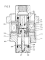
- FIG. 2 shows a further high-pressure injection valve, which is constructed similarly to that according to FIG. 1. Two slightly different versions are shown on the right and left. Various options for fastening the magnetic pole and a particularly favorable design for setting the armature stroke are explained. Only the details deviating from Fig. 1 are discussed here.
- the magnetic circuit of the valve consists of the magnetic pole 204, the housing 201 and the armature 215. Furthermore, the magnetic yoke on the right side of FIG. 2 takes place through the carrier 214, which is screwed to the support sleeve 208. The magnetic pole 204 is screwed directly to the non-magnetizable support sleeve 208. On the left side of FIG. 2, the pole 204 is carried by a non-magnetizable sleeve 206, which is fastened within the lower support sleeve 207 made of magnetizable material. The attachment is preferably carried out by brazing or by laser welding.
- the machining of the end face of the magnetic pole 204 and the guide bore for the armature 215 can be carried out together in one setting, which makes it easy to maintain a precise rectangular position.
- the pole 204 and the armature 215 on the left side of FIG. 2 are each composed of two concentric parts.
- the armature 215 carries the sleeve 216 and the pole 204 carries the sleeve 204.
- the advantage of such an embodiment is reduced eddy current formation, since the individual parts can be made thinner overall.
- the armature stroke is adjusted by rotating the seat support 209.
- the seat support 209 is braced against the valve neck 208 without play.
- the bracing takes place through the spring action of the shoulder 213 above the sealing ring groove 220.
- the bracing seat bracket 209 achieves a high tensioning force with a particularly small size of the valve.
- a fitting ring 211 is arranged between the shoulder 213 and the shoulder of the valve neck 208.
- the fitting ring 211 is used for rough adjustment of the valve stroke.
- the fine calibration is then carried out after a test run of the valve by rotating the seat support 209 accordingly.
- a braceable shoulder can also be arranged on the outer circumference of the seat support, which then rests on the end of the neck 208 Edition reached.
- the necessary elasticity is then also achieved by an undercut groove within the seat support.
- the tensionable seat bracket 209 permits particularly simple and reliable static calibration of the valve. The required long-term stability of the adjustment would not be reliably guaranteed with a separate spring element.
- the tensionable seat support can also be used advantageously for low-pressure injection valves.
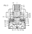
- FIG 3 shows a further high-pressure injection valve, the magnetic circuit of which has a double working air gap.
- the outside diameter of the valve is approx. 20 mm.
- the magnetic circuit of the valve consists of the armature 307, the central pole 302, the housing 301 and the side pole 306.
- the magnetic circuit has two working air gaps 315 and 316.
- the central working air gap 315 is arranged within the solenoid coil 303.
- the outer diameter of the central pole 302 is approximately 6-8 mm.
- the wall thickness of the central pole 302 is approximately 0.8-1.2 mm.
- the area of the two magnetic poles is approx. 15-20 mm2 each.
- armature 307 is tightened, a residual air gap of approximately 0.05 mm remains in the area of working poles 315 and 316.
- the valve stroke is preferably approximately 0.05-0.1 mm.
- the magnet coil 303 is wound on a coil body 304 made of non-magnetizable material.
- the coil body 304 serves to seal the coil space and can consist, for example, of austenitic steel or of high-strength ceramic.
- the coil space can be filled with a sealing compound to seal and improve the mechanical stability.
- the magnetic coil 303 can also be made from a thin film. Such a film spool has a very high mechanical and electrical stability, so that it is then also possible to dispense with a sealing of the coil space from the system pressure.
- the valve needle 308 has a side collar 322 to which the armature 307 is attached. The total moving mass of the armature 307 and the valve needle 308 together is approximately 1 g. The diameter of the valve needle 308 is approximately 2-2.5 mm.
- a ballic pin 317 is worked onto the valve needle 308 and closes the valve seat.
- the diameter of this pin 317 is approximately 0.8 mm.
- the non-pressure-equalized area of the valve seat 318 is approximately 0.3 mm2.
- the design pressure of the valve is approx. 500 bar.
- a stop pin 319 the diameter of which is approximately 0.5-0.8 mm, is machined onto the top of the valve needle 308.
- the stop pin 319 is surrounded by the damping chamber 320.
- the stop pin 319 comes to rest against the central stop 312 when the anchor 307 is tightened.
- the central stop 312 is made of non-magnetizable material and is fastened within the magnetic pole 302, for example by brazing.
- the valve needle 308 is clamped between two diaphragm springs 305 and 310, and is guided through them with little play in the radial direction.
- Diaphragm springs 305 and 310 are provided with openings to allow fuel to pass through.
- the vibration damper 313 is arranged between the armature 307 and the upper diaphragm spring 305.
- the return spring force can be set by selecting a suitable thickness of the vibration damper 313.
- Another vibration damper can be arranged between the lower diaphragm spring 310 and the valve needle 308.
- the coil former 304, the diaphragm spring 305 and the side pole 306 are clamped within the housing 301 by the seat support 309.
- the seat support 309 is designed to be elastic in the area of the sealing ring groove 311, so that the valve lift can be calibrated by screwing the seat support 309 in correspondingly deeply.
- the fuel supply to the valve seat 318 takes place through the central connecting piece 325 on the housing 301, through lateral grooves in the central stop 312 and in the collar 322 of the valve needle 308, and further through the openings in the diaphragm springs 305 and 310.
- the advantage of the above valve design compared to the valve designs according to FIG. 1 and FIG. 2 is less eddy current formation, since the magnetic circuit can be made thinner-walled at a predetermined maximum magnetic force.
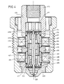
- FIG. 4 shows a high-pressure injection valve with a polarized magnetic circuit.
- the basic structure of the polarized magnetic circuit is known.
- the design pressure of the valve is approx. 1000 bar.
- the outside diameter of the valve is approx. 22 mm.
- the valve allows the fastest positioning movements.
- the disadvantage is a considerably increased construction effort.
- a monostable version is understood to mean a valve which automatically goes into the closed position after the excitation current has been switched off.
- the monostable version offers the advantage of increased safety in the event of malfunctions in the electrical control circuit.
- an electrical counter pulse is required to close the valve.
- the bistable design offers the advantage of better efficiency and thus a higher working speed.
- the valve shown has a friction-free armature suspension between two diaphragm springs with a very steep spring characteristic. The spring force is zero when the valve is in the half-open position.
- the maximum spring force is reached in the respective end positions of the valve both in the open and in the closed position.
- the spring force in the closed position of the valve should correspond approximately to the sum of the permanent magnetic force of the magnetic circuit and the closing force required for safety reasons.
- injection valves with polarized magnetic circuits can achieve much faster actuating movements than with the usual flat spring characteristic curves.
- Flat spring characteristics would result when using coil springs.
- the valve is suitable for a fuel pressure of up to approx. 1000 bar.
- the polarized solenoid valve according to FIG. 4 has a tubular armature 415 which is firmly connected to the valve needle 416.
- the outer diameter of the armature 415 is preferably 7-8 mm.
- the wall thickness of the anchor is preferably approximately 0.8-1.2 mm.
- the total mass of armature 415 and valve needle 416 is approximately 1.5 g.
- the valve needle 416 is suspended on the top and bottom in the diaphragm springs 413 and 414.
- the characteristic curve of the diaphragm springs 413 and 414 is calibrated by grinding the flat side of these springs accordingly.
- the vibration absorbers 417 and 418 are arranged between the diaphragm springs 413 and 414 and the valve needle 416.
- the diaphragm springs 413 and 414 are provided with openings which allow fuel to pass through.
- the armature stroke is limited by the upper stop 411, against which the valve needle 416 comes to a stop when the valve is open.
- the two magnetic poles of the valve are arranged within non-magnetizable sleeves.
- the bistable valve on the right side of Fig. 4 has a magnetically symmetrical structure.
- air gaps 423 and 424 are only arranged between the armature 415 and the two magnetic poles 409 and 410.
- the non-magnetizable sleeve 420 forms an additional air gap between the upper magnetic pole 419 and the sealing plug 426. This additional air gap weakens the magnetic field within the upper working air gap 424. This ensures that the armature 415 automatically returns to the rest position by the stronger magnetic field in the region of the lower working air gap 423.
- residual air gaps 423 and 424 of preferably approximately 0.05 mm each.
- the residual air gaps are required to avoid hydraulic sticking.
- a desired hydraulic damping of the actuating movements is achieved in the area of the residual air gaps.
- a monostable mode of operation can also be achieved through an asymmetrical arrangement of the residual air gaps 423 and 424.
- the upper residual air gap 424 is made considerably longer than the lower residual air gap 423, so that a correspondingly stronger permanent magnetic field is formed in the area of the lower residual air gap 423, which causes the independent resetting.
- the monostable arrangement shown on the left-hand side of FIG. 4 with an additional magnetic air gap between pole 419 and sealing plug 426 is more favorable in terms of magnet technology.
- the permanent magnetic field is generated by the permanent magnet 402, which can be made up of several separate segments.
- the inner magnetic yoke to the armature 415 takes place through the central pole 403.
- the outer magnetic yoke to the two magnetic poles 409 and 410 takes place through the valve housing 401, the upper sealing plug 412 and the seat support 408.
- the central pole 403 is with the non-magnetizable sleeves 404 and 405 or 420 firmly connected.
- the connection is preferably made by laser welding or by brazing.
- the electrical excitation takes place through the two solenoid coils 406 and 407.
- the inner parts of the valve are clamped together with the upper sealing plug 412 in the valve housing 401.
- the interior of the valve is acted on by the full system pressure.
- the installation spaces of the solenoids 406 and 407 are sealed against the system pressure.
- valve according to the invention can also be equipped with a simple nozzle shape other than that shown.
- Such other nozzle shapes are known from the usual mechanical injection nozzles. These known nozzle shapes can be used in miniaturized form without further ado in the valve according to the invention.
- the valve can be equipped with a miniaturized pin nozzle to improve atomization, in which case the pin diameter should be approximately 0.5-0.7 mm.
- the atomization can also be improved by using very short nozzles with a length of less than 0.5 mm.
- the mouth of such a nozzle can be sunk to improve the mechanical strength.
- the use of such short nozzles is made possible in the valve according to the invention because of the low mechanical load in the seat area.
- the nozzle on the combustion chamber side can be provided with a radius with a radius of a few 1/100 mm or with a conical outlet, which also improves atomization and achieves a larger spray cone.
- Vertebral bodies for generating a fuel swirl can be arranged within the injection nozzle or on the valve needle.
- a blind hole can be arranged below the valve seat, which supplies one or more obliquely arranged nozzles with fuel. This makes it possible to change the beam direction.
- the flow quality in the inflow region of the nozzle is considerably impaired by the blind hole, which overall always results in a considerable deterioration in the dynamic properties of the valve. Blind holes below the valve seat should therefore be avoided if possible in the valve according to the invention.
- the valve according to the invention could theoretically also be equipped with a collar-shaped stop which partially encompasses the valve needle.
- the collar-shaped stop can have a single or several radially evenly distributed separate stop areas.
- the stop surface of such a stop would only have to be made sufficiently small.
- Such a stop shape is generally known from the field of low-pressure injection valves.
- With a collar-shaped stop however, there are extremely great difficulties in maintaining an exact parallelism of the stop surfaces. It is hardly possible to maintain the required parallelism even with very precise machining methods.
- such a high-pressure injection valve with a collar-shaped stop will often result in strongly fluctuating hydraulic adhesive forces which result in impermissible, strongly fluctuating closing times of the valve. Such an embodiment causes a high manufacturing scrap. Therefore, the high-pressure injector according to the invention will always prefer the design proposed here with a single central stop.
Abstract
Claims (10)
- Soupape électromagnétique d'injection à haute pression, qui sert à injecter du carburant directement dans la chambre de combustion de moteurs à combustion interne, comportant un obturateur de soupape (113) en forme de pointeau, qui est relié rigidement à l'armature (112) d'un électroaimant, l'obturateur de soupape étant mobile, conjointement avec l'armature, le long d'un axe central de la soupape d'injection, et son mouvement de déplacement étant limité d'une part par un siège de soupape (120) et d'autre part par un élément de butée (126),
caractérisée par le fait- que l'armature (112) est entourée complètement du carburant à haute pression,- que la masse totale des parties mobiles de la soupape d'injection est égale au maximum à 2,5 g et de préférence est comprise entre 1 et 2,5 g,- que l'élément de butée (126) possède une surface de butée, qui est coupée par l'axe central de la soupape d'injection, et- qu'aussi bien la surface de contact entre l'armature (112) et la surface de butée que la section transversale, non compensée en pression, de l'obturateur de soupape (119) sont respectivement inférieures à 1 mm² et sont comprises, de préférence, entre 0,2 et 0,5 mm², lorsque l'obturateur de soupape est appliqué sur le siège de soupape (120). - Soupape d'injection suivant la revendication 1,
caractérisée par le fait- qu'elle comporte un support (117) du siège de soupape,- qui est fixé par vissage sur la soupape d'injection et qui est bloqué par rapport à cette dernière,- dont la profondeur de vissage permet d'ajuster la course de l'armature, et- qui est pourvu d'une gorge circonférentielle (220), dont le diamètre intérieur est inférieur au diamètre du filetage et qui délimite une zone déformable en forme de collet (213) du support (117) du siège de soupape, qui est bloqué mécaniquement par rapport à la soupape d'injection. - Soupape d'injection suivant la revendication 1,
caractérisée par le fait- qu'elle possède un amortisseur d'oscillations (111) servant à amortir le rebond de fermeture de l'obturateur de soupape (119), qui est repoussé contre le siège de soupape (120) par la force d'un ressort de rappel (110) et qui est soumis à la pression complète du carburant,- que l'amortisseur d'oscillations (114) entoure le pointeau (113) de la soupape et est repoussé contre ce dernier par un ressort supplémentaire (115), dont la force est dirigée en sens opposé à celle du ressort de rappel (110),- que la force élastique du ressort supplémentaire (115) est égale seulement à une fraction -de préférence environ 10 %- de la force du ressort de rappel (110), et- que la masse de l'amortisseur d'oscillations (114) est égale seulement à une fraction -de préférence environ 10 à 20 %- de la masse des autres parties mobiles de la soupape. - Soupape d'injection suivant la revendication 1,
caractérisée par le fait- qu'elle possède un circuit magnétique polarisé permettant l'actionnement rapide de la soupape avec une course de l'armature inférieure à 0,3 mm - égale de préférence à environ 0,1 mm,- que l'armature (415) du circuit magnétique est suspendue entre au moins deux ressorts (413,414), qui possèdent une courbe caractéristique d'élasticité très abrupte et qui appliquent des forces de sens réciproquement opposé l'une à l'autre,- que la force résultante des ressorts (413,414) dans les positions d'extrémité respectives est de sens opposé de la force de l'aimant permanent, et- que la force élastique résultante des ressorts (413,414) est nulle dans une position intermédiaire de l'armature (414) et atteint des valeurs extrèmes dans les positions d'extrémité respectives de l'armature. - Soupape d'injection suivant la revendication 1, caractérisée par le fait
que le pôle magnétique (108,205) de la soupape est porté par une douille non aimantable (107,208), qui sert à guider radialement l'armature (112,215). - Soupape d'injection suivant la revendication 1, caractérisée par le fait
que l'armature (112,307) de la soupape a une forme tubulaire ou une forme en chapeau et qu'un entrefer de travail (127,315) du circuit magnétique est disposé à l'intérieur de la bobine magnétique (105,303). - Soupape d'injection suivant la revendication 6, caractérisée par le fait
que l'armature est guidée radialement par au moins un ressort à membrane (305). - Soupape d'injection suivant la revendication 1, caractérisée par le fait que le pointeau (113,210,308) de la soupape porte une butée en forme de tige ou bombée (125,319), qui fait saillie de 30 à 100 microns de la face polaire de l'armature (112,215,307).
- Soupape d'injection suivant la revendication 1, caractérisée par le fait
qu'entre le ressort de rappel (110) et le pointeau (113) de la soupape est disposé un amortisseur d'oscillations (111), qui est porté par le pointeau de la soupape. - Soupape d'injection suivant la revendication 1, caractérisée par le fait
que le pointeau (113) de la soupape porte un téton qui traverse la buse d'injection (118) et dont le diamètre est compris entre environ 0,4 et 0,7 mm.
Applications Claiming Priority (2)
| Application Number | Priority Date | Filing Date | Title |
|---|---|---|---|
| DE3905992A DE3905992A1 (de) | 1989-02-25 | 1989-02-25 | Elektromagnetisches hochdruckeinspritzventil |
| DE3905992 | 1989-02-25 |
Publications (2)
| Publication Number | Publication Date |
|---|---|
| EP0459999A1 EP0459999A1 (fr) | 1991-12-11 |
| EP0459999B1 true EP0459999B1 (fr) | 1992-11-04 |
Family
ID=6374986
Family Applications (1)
| Application Number | Title | Priority Date | Filing Date |
|---|---|---|---|
| EP90902618A Expired - Lifetime EP0459999B1 (fr) | 1989-02-25 | 1990-02-12 | Soupape injectrice electromagnetique a haute pression |
Country Status (6)
| Country | Link |
|---|---|
| US (1) | US5127585A (fr) |
| EP (1) | EP0459999B1 (fr) |
| JP (1) | JPH03505769A (fr) |
| AU (1) | AU5036090A (fr) |
| DE (2) | DE3905992A1 (fr) |
| WO (1) | WO1990010151A1 (fr) |
Cited By (1)
| Publication number | Priority date | Publication date | Assignee | Title |
|---|---|---|---|---|
| DE10136808A1 (de) * | 2001-07-27 | 2003-02-13 | Bosch Gmbh Robert | Brennstoffeinspritzventil |
Families Citing this family (99)
| Publication number | Priority date | Publication date | Assignee | Title |
|---|---|---|---|---|
| IT1240180B (it) * | 1990-04-06 | 1993-11-27 | Weber Srl | Valvola dosatrice e polverizzatrice di carburante ad azionamento elettromagnetico per un dispositivo di alimentazione di un motore endotermico |
| DE4214284A1 (de) * | 1992-04-30 | 1993-11-04 | Schneider Co Optische Werke | Elektromagnetischer linearmotor |
| US5271565A (en) * | 1992-12-18 | 1993-12-21 | Chrysler Corporation | Fuel injector with valve bounce inhibiting means |
| WO1994016208A1 (fr) * | 1993-01-03 | 1994-07-21 | Bo Tan | Moteur rotatif a explosion a piston coulissant |
| JP2660388B2 (ja) * | 1993-12-29 | 1997-10-08 | 株式会社ケーヒン | 電磁式燃料噴射弁 |
| US5558066A (en) * | 1995-02-02 | 1996-09-24 | Cummins Engine Company, Inc. | Fuel system vibration damper |
| DE19543141A1 (de) * | 1995-11-18 | 1997-05-22 | Schultz Wolfgang E | Elektromagnet mit beweglichem Bremskörper |
| DE19543142A1 (de) * | 1995-11-18 | 1997-05-22 | Schultz Wolfgang E | Elektromagnet mit beweglichem Kernteil |
| EP0781915A1 (fr) * | 1995-12-26 | 1997-07-02 | General Motors Corporation | Injecteur de carburant |
| US5954312A (en) * | 1996-01-31 | 1999-09-21 | Siemens Automotive Corporation | Groove means in a fuel injector valve seat |
| FR2751701B1 (fr) * | 1996-07-23 | 1998-10-16 | Peugeot Motocycles Sa | Electrovanne notamment d'impact pour un systeme d'injection de carburant par effet de coup de belier dans un moteur de vehicule |
| US5875747A (en) * | 1997-03-26 | 1999-03-02 | Lamp; Justin | Internal combustion engine |
| US6250284B1 (en) | 1997-03-26 | 2001-06-26 | Justin Lamp | Engine with fuel delivery system |
| US5921475A (en) * | 1997-08-07 | 1999-07-13 | Ford Motor Company | Automotive fuel injector |
| US6047907A (en) | 1997-12-23 | 2000-04-11 | Siemens Automotive Corporation | Ball valve fuel injector |
| WO1999061780A1 (fr) * | 1998-05-27 | 1999-12-02 | Siemens Automotive Corporation | Injecteur pour gaz naturel comprime tolerant aux contaminants et organisation de la traversee de l'injecteur par le carburant gazeux |
| US6508418B1 (en) | 1998-05-27 | 2003-01-21 | Siemens Automotive Corporation | Contaminant tolerant compressed natural gas injector and method of directing gaseous fuel therethrough |
| US6328231B1 (en) | 1998-05-27 | 2001-12-11 | Siemens Automotive Corporation | Compressed natural gas injector having improved low noise valve needle |
| US6109541A (en) * | 1998-07-23 | 2000-08-29 | Caterpillar Inc. | Apparatus for reducing the bounce of a poppet valve |
| IT1309674B1 (it) * | 1999-03-26 | 2002-01-30 | Magneti Marelli Spa | Iniettore carburante |
| US6318646B1 (en) | 1999-03-26 | 2001-11-20 | MAGNETI MARELLI S.p.A. | Fuel injector |
| JP2000297720A (ja) * | 1999-04-13 | 2000-10-24 | Hitachi Ltd | 燃料噴射装置 |
| US6089467A (en) * | 1999-05-26 | 2000-07-18 | Siemens Automotive Corporation | Compressed natural gas injector with gaseous damping for armature needle assembly during opening |
| US6431474B2 (en) | 1999-05-26 | 2002-08-13 | Siemens Automotive Corporation | Compressed natural gas fuel injector having magnetic pole face flux director |
| US6422488B1 (en) | 1999-08-10 | 2002-07-23 | Siemens Automotive Corporation | Compressed natural gas injector having gaseous dampening for armature needle assembly during closing |
| US6405947B2 (en) | 1999-08-10 | 2002-06-18 | Siemens Automotive Corporation | Gaseous fuel injector having low restriction seat for valve needle |
| US6123275A (en) * | 1999-08-12 | 2000-09-26 | Delphi Technologies, Inc. | Dual gap fuel injector |
| US7021569B1 (en) | 2000-01-26 | 2006-04-04 | Hitachi, Ltd. | Fuel injection valve |
| US6758421B1 (en) | 2000-03-31 | 2004-07-06 | Siemens Automotive Corporation | Double concentric inlet tube for setting armature/needle lift and method of manufacturing same |
| US6676044B2 (en) * | 2000-04-07 | 2004-01-13 | Siemens Automotive Corporation | Modular fuel injector and method of assembling the modular fuel injector |
| US6799733B1 (en) * | 2000-06-28 | 2004-10-05 | Siemens Automotive Corporation | Fuel injector having a modified seat for enhanced compressed natural gas jet mixing |
| US6481646B1 (en) | 2000-09-18 | 2002-11-19 | Siemens Automotive Corporation | Solenoid actuated fuel injector |
| US6520421B2 (en) | 2000-12-29 | 2003-02-18 | Siemens Automotive Corporation | Modular fuel injector having an integral filter and o-ring retainer |
| US6568609B2 (en) | 2000-12-29 | 2003-05-27 | Siemens Automotive Corporation | Modular fuel injector having an integral or interchangeable inlet tube and having an integral filter and o-ring retainer assembly |
| US6547154B2 (en) | 2000-12-29 | 2003-04-15 | Siemens Automotive Corporation | Modular fuel injector having a terminal connector interconnecting an electromagnetic actuator with a pre-bent electrical terminal |
| US6698664B2 (en) | 2000-12-29 | 2004-03-02 | Siemens Automotive Corporation | Modular fuel injector having an integral or interchangeable inlet tube and having an integral filter and dynamic adjustment assembly |
| US6550690B2 (en) | 2000-12-29 | 2003-04-22 | Siemens Automotive Corporation | Modular fuel injector having interchangeable armature assemblies and having an integral filter and dynamic adjustment assembly |
| US6543707B2 (en) | 2000-12-29 | 2003-04-08 | Siemens Automotive Corporation | Modular fuel injector having a lift set sleeve |
| US6523760B2 (en) | 2000-12-29 | 2003-02-25 | Siemens Automotive Corporation | Modular fuel injector having interchangeable armature assemblies and having a terminal connector interconnecting an electromagnetic actuator with an electrical terminal |
| US6499668B2 (en) | 2000-12-29 | 2002-12-31 | Siemens Automotive Corporation | Modular fuel injector having a surface treatment on an impact surface of an electromagnetic actuator and having a terminal connector interconnecting an electromagnetic actuator with an electrical terminal |
| US6502770B2 (en) | 2000-12-29 | 2003-01-07 | Siemens Automotive Corporation | Modular fuel injector having a snap-on orifice disk retainer and having a terminal connector interconnecting an electromagnetic actuator with an electrical terminal |
| US6607143B2 (en) | 2000-12-29 | 2003-08-19 | Siemens Automotive Corporation | Modular fuel injector having a surface treatment on an impact surface of an electromagnetic actuator and having a lift set sleeve |
| US6499677B2 (en) | 2000-12-29 | 2002-12-31 | Siemens Automotive Corporation | Modular fuel injector having a low mass, high efficiency electromagnetic actuator and having an integral filter and dynamic adjustment assembly |
| US6533188B1 (en) | 2000-12-29 | 2003-03-18 | Siemens Automotive Corporation | Modular fuel injector having a snap-on orifice disk retainer and having an integral filter and dynamic adjustment assembly |
| US6769636B2 (en) | 2000-12-29 | 2004-08-03 | Siemens Automotive Corporation | Modular fuel injector having interchangeable armature assemblies and having an integral filter and O-ring retainer assembly |
| US6523761B2 (en) | 2000-12-29 | 2003-02-25 | Siemens Automotive Corporation | Modular fuel injector having an integral or interchangeable inlet tube and having a lift set sleeve |
| US6655609B2 (en) | 2000-12-29 | 2003-12-02 | Siemens Automotive Corporation | Modular fuel injector having a low mass, high efficiency electromagnetic actuator and having an integral filter and o-ring retainer assembly |
| US6565019B2 (en) | 2000-12-29 | 2003-05-20 | Seimens Automotive Corporation | Modular fuel injector having a snap-on orifice disk retainer and having an integral filter and O-ring retainer assembly |
| US6523756B2 (en) | 2000-12-29 | 2003-02-25 | Siemens Automotive Corporation | Modular fuel injector having a low mass, high efficiency electromagnetic actuator and having a lift set sleeve |
| US6708906B2 (en) * | 2000-12-29 | 2004-03-23 | Siemens Automotive Corporation | Modular fuel injector having a surface treatment on an impact surface of an electromagnetic actuator and having an integral filter and dynamic adjustment assembly |
| US6536681B2 (en) | 2000-12-29 | 2003-03-25 | Siemens Automotive Corporation | Modular fuel injector having a surface treatment on an impact surface of an electromagnetic actuator and having an integral filter and O-ring retainer assembly |
| US6811091B2 (en) | 2000-12-29 | 2004-11-02 | Siemens Automotive Corporation | Modular fuel injector having an integral filter and dynamic adjustment assembly |
| US6695232B2 (en) | 2000-12-29 | 2004-02-24 | Siemens Automotive Corporation | Modular fuel injector having interchangeable armature assemblies and having a lift set sleeve |
| US6511003B2 (en) | 2000-12-29 | 2003-01-28 | Siemens Automotive Corporation | Modular fuel injector having an integral or interchangeable inlet tube and having a terminal connector interconnecting an electromagnetic actuator with an electrical terminal |
| US6676043B2 (en) | 2001-03-30 | 2004-01-13 | Siemens Automotive Corporation | Methods of setting armature lift in a modular fuel injector |
| US6904668B2 (en) | 2001-03-30 | 2005-06-14 | Siemens Vdo Automotive Corp. | Method of manufacturing a modular fuel injector |
| US7093362B2 (en) | 2001-03-30 | 2006-08-22 | Siemens Vdo Automotive Corporation | Method of connecting components of a modular fuel injector |
| US6687997B2 (en) | 2001-03-30 | 2004-02-10 | Siemens Automotive Corporation | Method of fabricating and testing a modular fuel injector |
| DE10119982A1 (de) | 2001-04-24 | 2002-10-31 | Bosch Gmbh Robert | Kraftstoffeinspritzeinrichtung für eine Brennkraftmaschine |
| DE10131125A1 (de) * | 2001-06-28 | 2002-09-12 | Bosch Gmbh Robert | Magnetventil mit gedämpftem, einteiligem Ankerelement |
| US6851622B2 (en) * | 2002-01-08 | 2005-02-08 | Siemens Vdo Automotive Corporation | Fuel injector having a ferromagnetic coil bobbin |
| DE10202324A1 (de) * | 2002-01-23 | 2003-07-31 | Bosch Gmbh Robert | Magnetventil und Verfahren zu seiner Herstellung |
| JP2003232268A (ja) * | 2002-02-08 | 2003-08-22 | Hitachi Ltd | 電磁式燃料噴射弁 |
| DE10208225A1 (de) * | 2002-02-26 | 2003-10-30 | Bosch Gmbh Robert | Brennstoffeinspritzsystem |
| DE10325442A1 (de) * | 2003-06-05 | 2004-12-23 | Robert Bosch Gmbh | Magnetventil mit reduzierten Schaltgeräuschen |
| FR2875863B1 (fr) * | 2004-09-30 | 2009-05-01 | Peugeot Citroen Automobiles Sa | Dispositif d'injection a rayonnement accoustique reduit |
| JP2007278218A (ja) * | 2006-04-10 | 2007-10-25 | Denso Corp | 燃料噴射弁 |
| DE102007029064A1 (de) * | 2007-06-21 | 2008-12-24 | Focke & Co.(Gmbh & Co. Kg) | Ventil, insbesondere Leimventil |
| DE102007049945A1 (de) * | 2007-10-18 | 2009-04-23 | Robert Bosch Gmbh | Brennstoffeinspritzventil |
| CN101978152B (zh) * | 2008-03-17 | 2013-07-03 | 胡斯华纳有限公司 | 燃料供应单元 |
| GB0919645D0 (en) * | 2009-11-10 | 2009-12-23 | Sentec Ltd | Flux switched fuel injector |
| DE102010040914A1 (de) * | 2010-09-16 | 2012-03-22 | Robert Bosch Gmbh | Brennstoffeinspritzventil |
| DE102010040916A1 (de) * | 2010-09-16 | 2012-03-22 | Robert Bosch Gmbh | Brennstoffeinspritzventil |
| GB201207289D0 (en) | 2011-06-14 | 2012-06-06 | Sentec Ltd | Flux switch actuator |
| EP2589786A1 (fr) * | 2011-11-04 | 2013-05-08 | Continental Automotive GmbH | Ensemble de soupape pour vanne de contrôle et vanne de contrôle |
| US8436704B1 (en) | 2011-11-09 | 2013-05-07 | Caterpillar Inc. | Protected powder metal stator core and solenoid actuator using same |
| EP2608226B1 (fr) | 2011-12-23 | 2015-12-23 | Techspace Aero S.A. | Actionneur solénoïde à chemisage magnétique |
| DE102012204299A1 (de) * | 2012-03-19 | 2013-09-19 | Robert Bosch Gmbh | Magnetischer Aktor, Ventil, sowie Verwendung eines Materials bei magnetischen Aktoren |
| EP2700807A1 (fr) * | 2012-08-23 | 2014-02-26 | Continental Automotive GmbH | Ensemble de soupape pour soupape d'injection et soupape d'injection |
| DE102012112729B4 (de) * | 2012-12-20 | 2015-12-17 | Wp Performance Systems Gmbh | Dämpfungsventilanordnung für einen semiaktiven Schwingungsdämpfer |
| EP2775132A1 (fr) * | 2013-03-07 | 2014-09-10 | Continental Automotive GmbH | Corps de soupape et injecteur de fluide |
| EP2918816B1 (fr) * | 2014-03-14 | 2017-09-06 | Continental Automotive GmbH | Injecteur de carburant |
| US9627121B2 (en) * | 2014-05-28 | 2017-04-18 | Flextronics Automotive, Inc. | Solenoid robust against misalignment of pole piece and flux sleeve |
| JP6488134B2 (ja) | 2015-01-26 | 2019-03-20 | 日立オートモティブシステムズ株式会社 | 燃料噴射弁 |
| WO2016121475A1 (fr) * | 2015-01-30 | 2016-08-04 | 日立オートモティブシステムズ株式会社 | Robinet d'injection de carburant |
| DE102015005369A1 (de) * | 2015-04-25 | 2016-10-27 | Wabco Gmbh | Bistabiles Magnetventil für ein Fluidsystem, Magnetventil-Einrichtung und Verfahren zum Schalten des Magnetventils |
| EP3141736A1 (fr) * | 2015-09-09 | 2017-03-15 | Continental Automotive GmbH | Groupe d'alimentation pour un injecteur de carburant et injecteur de carburant |
| JP6538495B2 (ja) * | 2015-09-11 | 2019-07-03 | 日立オートモティブシステムズ株式会社 | 燃料噴射弁 |
| DE102015217362A1 (de) * | 2015-09-11 | 2017-03-16 | Continental Automotive Gmbh | Kraftstoffinjektor, Verfahren zum Ermitteln der Position eines beweglichen Ankers und Motorsteuerung |
| US9879645B2 (en) | 2016-02-18 | 2018-01-30 | Caterpillar Inc. | Control valve bounce limiting mechanism for fuel injectors |
| EP3222914B1 (fr) * | 2016-03-23 | 2019-01-09 | Orkli, S. Coop. | Valve de sécurité à gaz |
| GB2549095A (en) * | 2016-04-04 | 2017-10-11 | Delphi Int Operations Luxembourg Sarl | Fuel injector |
| DE102017105531A1 (de) * | 2017-03-15 | 2018-09-20 | Eto Magnetic Gmbh | Aktorvorrichtung und Verfahren zum Betrieb einer Aktorvorrichtung |
| DE102017120805A1 (de) * | 2017-09-08 | 2019-03-14 | Eto Magnetic Gmbh | Magnetventilvorrichtung |
| DE102018008266A1 (de) * | 2018-10-18 | 2020-04-23 | Gea Tuchenhagen Gmbh | Prozesskomponente |
| DE102018222614A1 (de) * | 2018-12-20 | 2020-06-25 | Robert Bosch Gmbh | Elektromagnetische Betätigungseinrichtung |
| DE102019104192A1 (de) * | 2019-02-19 | 2020-08-20 | Eto Magnetic Gmbh | Magnetaktorvorrichtung, magnetisch betätigbares Ventil, Verfahren mit der Magnetaktorvorrichtung und Verfahren zur Herstellung der Magnetaktorvorrichtung |
| DE102021111032A1 (de) | 2021-04-29 | 2022-11-03 | Samson Aktiengesellschaft | Elektromagnetischer Antrieb für beispielsweise ein 3/2-Wegeventil und 3/2-Wegeventil |
| WO2023059662A1 (fr) | 2021-10-04 | 2023-04-13 | Billet Machine And Fabrication, Inc. | Injecteur de combustible |
Citations (1)
| Publication number | Priority date | Publication date | Assignee | Title |
|---|---|---|---|---|
| EP0017719A1 (fr) * | 1979-04-23 | 1980-10-29 | Rockwell International Corporation | Procédé de fabrication microélectronique minimisant les variations de tension de seuil |
Family Cites Families (31)
| Publication number | Priority date | Publication date | Assignee | Title |
|---|---|---|---|---|
| BE440388A (fr) * | 1940-02-12 | |||
| US2881980A (en) * | 1957-05-10 | 1959-04-14 | Bendix Aviat Corp | Fuel injection nozzle |
| GB1064679A (en) * | 1962-12-03 | 1967-04-05 | Ass Eng Ltd | Fuel injectors for internal combustion engines |
| CH426414A (fr) * | 1965-08-27 | 1966-12-15 | Lucifer Sa | Electro-valve |
| DE1263396B (de) * | 1966-04-20 | 1968-03-14 | Philips Patentverwaltung | Magnetventil fuer eine Brennstoffeinspritzanlage fuer Brennkraftmaschinen |
| DE2062420A1 (de) * | 1970-12-18 | 1972-06-22 | Bosch Gmbh Robert | Elektromagnetisch betätigbares Kraftstoff-Einspritzventil für eine Brennkraftmaschine |
| FR2206795A5 (fr) * | 1972-11-13 | 1974-06-07 | Motobecane Ateliers | |
| DD101783A1 (fr) * | 1972-12-20 | 1973-11-12 | ||
| DE2548774A1 (de) * | 1975-10-31 | 1977-05-05 | Bosch Gmbh Robert | Elektromagnetventil |
| JPS5321450A (en) * | 1976-08-11 | 1978-02-27 | Matsushita Refrig Co | Insulating box |
| JPS6015967B2 (ja) * | 1977-07-20 | 1985-04-23 | 日本電気株式会社 | 桁あふれ検出可能な3入力直列全加算器 |
| US4306683A (en) * | 1980-07-21 | 1981-12-22 | General Motors Corporation | Electromagnetic fuel injector with adjustable armature spring |
| US4310123A (en) * | 1980-07-21 | 1982-01-12 | General Motors Corporation | Electromagnetic fuel injector with adjustable armature spring |
| DE3031564A1 (de) * | 1980-08-21 | 1982-04-08 | Robert Bosch Gmbh, 7000 Stuttgart | Elektromagnetisches kraftstoffeinspritzventil und verfahren zur herstellung eines elektromagnetischen kraftstoffeinspritzventiles |
| AT372417B (de) * | 1980-08-21 | 1983-10-10 | Zimmer Johannes Gmbh | Spritzduese |
| US4405912A (en) * | 1982-01-28 | 1983-09-20 | General Motors Corporation | Solenoid assembly and method of making same |
| IT1152503B (it) * | 1982-08-18 | 1987-01-07 | Alfa Romeo Spa | Elettroiniettore per un motore a c.i. |
| US4552312A (en) * | 1983-01-14 | 1985-11-12 | Tohoku Mikuni Kogyo Kabushiki Kaisha | Fuel injection valve |
| DE3314899A1 (de) * | 1983-04-25 | 1984-10-25 | Mesenich, Gerhard, Dipl.-Ing., 4630 Bochum | Federanordnung mit zusatzmasse zur verbesserung des dynamischen verhaltens von elektromagnetsystemen |
| DE3314900A1 (de) * | 1983-04-25 | 1984-10-25 | Gerhard Dipl.-Ing. 4630 Bochum Mesenich | Elektromagnet fuer ventile |
| DE3320610A1 (de) * | 1983-06-08 | 1984-12-13 | Gerhard Dipl.-Ing. 4630 Bochum Mesenich | Einspritzventil fuer verbrennungsmotoren |
| DE3332801A1 (de) * | 1983-09-12 | 1985-03-28 | Robert Bosch Gmbh, 7000 Stuttgart | Ventil fuer gasfoermige oder fluessige medien |
| DE3408012A1 (de) * | 1984-03-05 | 1985-09-05 | Gerhard Dipl.-Ing. Warren Mich. Mesenich | Elektromagnetisches einspritzventil |
| DE3437162A1 (de) * | 1984-10-10 | 1986-04-17 | Vdo Adolf Schindling Ag, 6000 Frankfurt | Elektromagnetisch betaetigbares kraftstoffeinspritzventil |
| DE3446410A1 (de) * | 1984-12-20 | 1986-06-26 | Wabco Westinghouse Steuerungstechnik GmbH & Co, 3000 Hannover | Betaetigungseinrichtung fuer ventile |
| DE3531153A1 (de) * | 1985-06-14 | 1986-12-18 | Pierburg Gmbh & Co Kg, 4040 Neuss | Elektromagnetisches, intermittierendes einspritzventil |
| DE3527174A1 (de) * | 1985-07-30 | 1987-02-12 | Bosch Gmbh Robert | Doppeltwirkendes magnetventil |
| DE3704541A1 (de) * | 1987-02-13 | 1988-09-01 | Vdo Schindling | Kraftstoff-einspritzventil |
| IT210505Z2 (it) * | 1987-02-25 | 1988-12-30 | Iveco Fiat | Elettrovalvola particolarmente per iniettori di di motori a combustione interna |
| US4766405A (en) * | 1987-04-14 | 1988-08-23 | Allied Corporation | Dynamic energy absorber |
| JP2564861B2 (ja) * | 1987-11-23 | 1996-12-18 | 日本電装株式会社 | 内燃機関用電磁式燃料噴射弁 |
-
1989
- 1989-02-25 DE DE3905992A patent/DE3905992A1/de not_active Withdrawn
-
1990
- 1990-02-12 WO PCT/DE1990/000092 patent/WO1990010151A1/fr active IP Right Grant
- 1990-02-12 DE DE9090902618T patent/DE59000434D1/de not_active Expired - Fee Related
- 1990-02-12 JP JP2502547A patent/JPH03505769A/ja active Pending
- 1990-02-12 EP EP90902618A patent/EP0459999B1/fr not_active Expired - Lifetime
- 1990-02-12 AU AU50360/90A patent/AU5036090A/en not_active Abandoned
-
1991
- 1991-08-26 US US07/749,884 patent/US5127585A/en not_active Expired - Fee Related
Patent Citations (1)
| Publication number | Priority date | Publication date | Assignee | Title |
|---|---|---|---|---|
| EP0017719A1 (fr) * | 1979-04-23 | 1980-10-29 | Rockwell International Corporation | Procédé de fabrication microélectronique minimisant les variations de tension de seuil |
Cited By (1)
| Publication number | Priority date | Publication date | Assignee | Title |
|---|---|---|---|---|
| DE10136808A1 (de) * | 2001-07-27 | 2003-02-13 | Bosch Gmbh Robert | Brennstoffeinspritzventil |
Also Published As
| Publication number | Publication date |
|---|---|
| EP0459999A1 (fr) | 1991-12-11 |
| US5127585A (en) | 1992-07-07 |
| DE59000434D1 (de) | 1992-12-10 |
| JPH03505769A (ja) | 1991-12-12 |
| WO1990010151A1 (fr) | 1990-09-07 |
| DE3905992A1 (de) | 1989-09-21 |
| AU5036090A (en) | 1990-09-26 |
Similar Documents
| Publication | Publication Date | Title |
|---|---|---|
| EP0459999B1 (fr) | Soupape injectrice electromagnetique a haute pression | |
| EP0897469B1 (fr) | Vanne electromagnetique | |
| EP1137877B1 (fr) | Soupape d'injection de carburant | |
| EP1208298B1 (fr) | Soupape d'injection de carburant et procede de production d'orifices de sortie dans les soupapes | |
| EP0904488B1 (fr) | Soupape d'injection de carburant et procede de production d'un pointeau d'une telle soupape | |
| EP1266135B1 (fr) | Electrovanne destinee a commander la soupape d'injection d'un moteur a combustion interne | |
| EP1270930B1 (fr) | Vanne electromagnetique pour piloter un injecteur d'un moteur a combustion interne | |
| EP0880647A1 (fr) | Electrovanne | |
| DE3408012A1 (de) | Elektromagnetisches einspritzventil | |
| DE3834444A1 (de) | Elektromagnetisches einspritzventil mit membranfeder | |
| EP1309793A1 (fr) | Soupape d'injection de carburant | |
| EP1315900A1 (fr) | Soupape d'injection de carburant | |
| DE3035453A1 (de) | Elektromagnetische kraftstoffeinspritzvorrichtung | |
| EP2156046A1 (fr) | Ajustement de trajet d'armature pour électrovanne | |
| EP0496844A1 (fr) | Procede pour le reglage d'une soupape et soupape. | |
| DE10131199A1 (de) | Magnetventil zur Steuerung eines Einspritzventils einer Brennkraftmaschine | |
| DE3834446A1 (de) | Elektromagnetisches einspritzventil in patronenbauweise | |
| DE3601710C2 (de) | Kraftstoffeinspritzvorrichtung für Brennkraftmaschinen | |
| EP1339969A1 (fr) | Electrovanne destinee a la commande d'un injecteur d'un moteur a combustion interne | |
| DE3909893A1 (de) | Elektromagnetisch betaetigbares ventil | |
| DE3741526C2 (fr) | ||
| EP1402171B1 (fr) | Soupape d'injection de carburant et procede de reglage | |
| DE10055513B4 (de) | Brennstoffeinspritzventil | |
| DE102004013413A1 (de) | Kraftstoff-Einspritzventil | |
| DE102014200884A1 (de) | Kraftstoffinjektor |
Legal Events
| Date | Code | Title | Description |
|---|---|---|---|
| PUAI | Public reference made under article 153(3) epc to a published international application that has entered the european phase |
Free format text: ORIGINAL CODE: 0009012 |
|
| 17P | Request for examination filed |
Effective date: 19910809 |
|
| AK | Designated contracting states |
Kind code of ref document: A1 Designated state(s): DE FR GB IT |
|
| 17Q | First examination report despatched |
Effective date: 19920422 |
|
| GRAA | (expected) grant |
Free format text: ORIGINAL CODE: 0009210 |
|
| AK | Designated contracting states |
Kind code of ref document: B1 Designated state(s): DE FR GB IT |
|
| REF | Corresponds to: |
Ref document number: 59000434 Country of ref document: DE Date of ref document: 19921210 |
|
| ET | Fr: translation filed | ||
| ITF | It: translation for a ep patent filed |
Owner name: STUDIO JAUMANN |
|
| GBT | Gb: translation of ep patent filed (gb section 77(6)(a)/1977) |
Effective date: 19930108 |
|
| PLBE | No opposition filed within time limit |
Free format text: ORIGINAL CODE: 0009261 |
|
| STAA | Information on the status of an ep patent application or granted ep patent |
Free format text: STATUS: NO OPPOSITION FILED WITHIN TIME LIMIT |
|
| 26N | No opposition filed | ||
| REG | Reference to a national code |
Ref country code: GB Ref legal event code: IF02 |
|
| PGFP | Annual fee paid to national office [announced via postgrant information from national office to epo] |
Ref country code: GB Payment date: 20030206 Year of fee payment: 14 |
|
| PGFP | Annual fee paid to national office [announced via postgrant information from national office to epo] |
Ref country code: FR Payment date: 20030227 Year of fee payment: 14 |
|
| PGFP | Annual fee paid to national office [announced via postgrant information from national office to epo] |
Ref country code: DE Payment date: 20030417 Year of fee payment: 14 |
|
| PG25 | Lapsed in a contracting state [announced via postgrant information from national office to epo] |
Ref country code: GB Free format text: LAPSE BECAUSE OF NON-PAYMENT OF DUE FEES Effective date: 20040212 |
|
| PG25 | Lapsed in a contracting state [announced via postgrant information from national office to epo] |
Ref country code: DE Free format text: LAPSE BECAUSE OF NON-PAYMENT OF DUE FEES Effective date: 20040901 |
|
| GBPC | Gb: european patent ceased through non-payment of renewal fee |
Effective date: 20040212 |
|
| PG25 | Lapsed in a contracting state [announced via postgrant information from national office to epo] |
Ref country code: FR Free format text: LAPSE BECAUSE OF NON-PAYMENT OF DUE FEES Effective date: 20041029 |
|
| REG | Reference to a national code |
Ref country code: FR Ref legal event code: ST |
|
| PG25 | Lapsed in a contracting state [announced via postgrant information from national office to epo] |
Ref country code: IT Free format text: LAPSE BECAUSE OF NON-PAYMENT OF DUE FEES;WARNING: LAPSES OF ITALIAN PATENTS WITH EFFECTIVE DATE BEFORE 2007 MAY HAVE OCCURRED AT ANY TIME BEFORE 2007. THE CORRECT EFFECTIVE DATE MAY BE DIFFERENT FROM THE ONE RECORDED. Effective date: 20050212 |