EP1136847A2 - Retroreflektierende Folie mit dreieck-pyramidischen Würfelecken - Google Patents
Retroreflektierende Folie mit dreieck-pyramidischen Würfelecken Download PDFInfo
- Publication number
- EP1136847A2 EP1136847A2 EP00107190A EP00107190A EP1136847A2 EP 1136847 A2 EP1136847 A2 EP 1136847A2 EP 00107190 A EP00107190 A EP 00107190A EP 00107190 A EP00107190 A EP 00107190A EP 1136847 A2 EP1136847 A2 EP 1136847A2
- Authority
- EP
- European Patent Office
- Prior art keywords
- triangular
- faces
- pyramidal
- elements
- retroreflective
- Prior art date
- Legal status (The legal status is an assumption and is not a legal conclusion. Google has not performed a legal analysis and makes no representation as to the accuracy of the status listed.)
- Granted
Links
Images


Classifications
-
- G—PHYSICS
- G02—OPTICS
- G02B—OPTICAL ELEMENTS, SYSTEMS OR APPARATUS
- G02B5/00—Optical elements other than lenses
- G02B5/12—Reflex reflectors
- G02B5/122—Reflex reflectors cube corner, trihedral or triple reflector type
- G02B5/124—Reflex reflectors cube corner, trihedral or triple reflector type plural reflecting elements forming part of a unitary plate or sheet
Definitions
- the present invention relates to a triangular-pyramidal cube-corner retroreflective sheeting having a novel structure. More minutely, the present invention relates to a cube-corner retroreflective sheeting in which triangular-pyramidal reflective elements having a novel structure are arranged in a closest-packed state.
- the present invention relates to a cube-corner retroreflective sheeting constituted of triangular-pyramidal cube-corner retroreflective elements (hereafter referred to as triangular-pyramidal reflective elements or merely, elements) useful for signs including license plates of automobiles and motorcycles, safety materials of clothing and life jackets, markings of signboards, and reflectors of visible-light, laser-beam, and infrared-ray reflective sensors.
- triangular-pyramidal cube-corner retroreflective elements hereafter referred to as triangular-pyramidal reflective elements or merely, elements
- the present invention relates to triangular-pyramidal cube-corner retroreflective sheeting in which a pair of triangular-pyramidal cube-corner retroreflective elements partitioned by three lateral faces (faces a 1 , b 1 , and c 1 ; faces a 2 , b 2 , and c 2 ; ...) almost perpendicularly intersecting each other because V-shaped grooves having substantially-symmetric cross sections intersect each other are arranged in a closest-packed state so as to protrude to one side on a common bottom plane (S-S'), faced lateral faces (faces c 1 and c 2 ) of this pair of triangular-pyramidal retroreflective elements are paired by sharing a base (x), the bottom face (S-S') is a common plane including bases (z and z) of one-side lateral faces (faces a 1 and a 2 ) and bases (y and y) of the other-side
- the present invention relates to a triangular-pyramidal cube-corner retroreflective sheeting in which a pair of triangular-pyramidal cube-corner retroreflective elements partitioned by three lateral faces (faces a 1 , b 1 , and c 1 ; faces a 2 , b 2 , and c 2 ; ...) almost perpendicularly intersecting each other because V-shaped grooves having substantially-symmetric cross sections intersect each other have substantially optically analogous shapes and thereby, have angles ⁇ (hereafter also referred to as tilts of optical axes) formed between substantially same optical axes though different from each other in direction by 180° and a vertical line.
- ⁇ hereafter also referred to as tilts of optical axes
- a retroreflective sheeting for reflecting entrance light toward a light source has been well known so far and the sheeting using its retroreflective characteristic is widely used in the above fields.
- a cube-corner retroreflective sheeting using the retroreflective theory of a cube-corner retroreflective element such as a triangular-pyramidal retroreflective element is extremely superior to a conventional retroreflective sheeting using micro glass beads in retroreflectivity and its purpose has been expanded year by year because of its superior retroreflective performance.
- a conventionally-publicly-known triangular-pyramidal retroreflective element shows a preferable retroreflectivity when an angle formed between an axis vertical to a sheet plane (axis passing through the apex of the triangular pyramid of the triangular-pyramidal retroreflective element equally separate from three faces constituting a triangular-pyramidal cube-corner retroreflective element and intersecting each other at an angle of 90°) and entrance light (the angle is hereafter referred to as entrance angle) is kept in a small range.
- the retroreflectivity rapidly deteriorates as the entrance angle increases (that is, the entrance angularity deteriorates).
- the light entering the triangular-pyramidal retroreflective element face at an angle less than a critical angle ( ⁇ c ) satisfying an internal total-reflection condition determined by the ratio between the refractive index of a transparent medium constituting the triangular-pyramidal retroreflective element and the refractive index of air penetrates into the back of the element without totally reflecting on the interface of the element. Therefore, a retroreflective sheeting using a triangular-pyramidal retroreflective element generally has a disadvantage that it is inferior in entrance angularity.
- a triangular-pyramidal retroreflective element can reflect light in the light entrance direction almost over the entire surface of the element, retroreflected light is not diverged at a wide angle due to spherical aberration differently from the case of a micro-glass-bead reflective element.
- the narrow dispersion angle of the retroreflected light practically easily causes a trouble that, when the light emitted from a head lamp of an automobile is retroreflected on a traffic sign, the retroreflected light hardly reaches, for example, a driver present at a position distant from the axis of the incident light.
- the above trouble more frequently occurs because the angle (observation angle) formed between the entrance axis of a light ray and the axis (observation axis) connecting a driver and a reflective point increases (that is, the observation angularity deteriorates).
- FIG. 15 in the US patent illustrates a triangular-pyramidal reflective element whose optical axis tilts in the direction to be plus (+) as described later.
- the tilt angle ( ⁇ ) of the optical axis is estimated as approx. 6.5° when obtaining it from the ratio between the major and minor sides of the base triangle of the illustrated triangular-pyramidal reflective element.
- Stamm's UP Pat. No. 3,712,706 discloses a retroreflective sheeting in which so-called equilateral triangular-pyramidal cube-corner retroreflective elements whose base triangles are equilateral triangles are arranged on a thin sheeting so that their bottom faces are brought into a closest-packed state on a common plane. Stamm's US patent solves the problems that retroreflectivity is deteriorated and light entrance at an angle of less than an internal total reflection condition passes through an interface between elements and thereby it is not retroreflected by vacuum-depositing with a metal such as aluminum on the reflective surface of a reflective element, mirror-reflecting entrance light, and increasing an entrance angle.
- a metal such as aluminum on the reflective surface of a reflective element, mirror-reflecting entrance light, and increasing an entrance angle.
- Hoopman's European Pat. No. 137,736B1 describes a retroreflective sheeting in which a pair of tilted triangular-pyramidal cube-corner retroreflective elements whose base triangles are isosceles triangles are arranged on a thin sheeting while rotated by 180° from each other and whose bottom faces are arranged on a common plane in a closest-packed state.
- Optical axes of the triangular-pyramidal cube-corner retroreflective elements described in the above patent tilt in the minus (-) direction described in this specification and it is shown that the tilt angle ranges between 7° and 13°.
- an optical axis tilts so that the distance (p) between a face including a common side of paired elements and vertical to a common plane and the apex of an element is not equal to the distance (q) between a point at which the optical axis of an element intersects with the common plane and the vertical face and a tilt angle of the optical axis ranges between approx. 2° and 5°, and the height from the common plane up to the apex of an element ranges between 25 and 100 ⁇ m.
- Every retroreflective sheeting constituted of a triangular-pyramidal retroreflective element whose bottom face is present on the same face is inferior in entrance angularity, that is, every retroreflective sheeting has a disadvantage that retroreflective brightness rapidly decreases when the entrance angle of light to the triangular-pyramidal retroreflective elements increases.
- a retroreflective sheeting obtained through the method proposed by Appeldorn et al. can be a sheeting whose entrance angularity and observation angularity are improved to a certain extent.
- very complex operations are required together with a very-high accuracy and skill.
- a retroreflective element assembly is also publicly known which includes an asymmetric retroreflective element pair in which three-directional V-shaped grooves do not intersect at one point.
- the official gazette of International Patent Publication No. 94/14,091 (WO94/14091) by Gubela discloses a unique retroreflective body and its forming method in order to providing wide angularity for retroreflected light by decreasing the non-retroreflective surface of the retroreflective body.
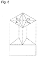
- the retroreflective body is constituted by setting a hexagonal pyramid whose bottom face is an equilateral hexagon (A 0 -D 1 -E 1 -B 0 -E 2 -D 2 ) to the central portion of the bottom face of a rhombus formed when two-directional V-shaped grooves shown in FIGs.
- another-directional V-shaped grooves (E 1 -E 1 and D 2 -E 2 ) do not pass through the apex of a rhombus (A 0 -C 1 -B 0 -C 2 ) formed by four V-shaped grooves (A 0 -C 1 , B 0 -C 2 , A 0 -C 2 , and B 0 -C 1 ) and an offset value from the apex (H 0 ) of the another-directional V-shaped grooves is equal to 25% of the length of the longer diagonal line of the rhombus (that is, in FIGs.
- intervals between C 1 -C 1 , E 1 -E 1 , B 0 -H 0 , E 2 -E 2 , and C 2 -C 2 ) shown by dotted extension lines are equal to each other and are 1/4 the interval between C 1 -C 1 and C 2 -C 2 ).
- a pair of equilateral triangular pyramids which have the same height and which are symmetric and one hexagonal pyramid whose bottom face is an equilateral triangle (A 0 -D 1 -E 1 -B 0 -E 2 -D 2 ) are formed in the rhombus.
- no description or suggestion about a retroreflective-element assembly specified by the present invention is present in the official gazette.
- the retroreflective body by Benson et al. is cut so that another-directional tilted V-shaped groove does not pass through the intersection between rhombic base shapes formed by two-directional tilted V-shaped grooves and can be constituted of various reflective elements including elements having no retroreflectivity by changing the intersection angle, depth, V-shaped-groove angle, number of grooves, and degree of V-shaped-groove tilt of the two-directional V-shaped grooves and the offset position, number of grooves, depth, V-groove angle, and degree of V-shaped-groove tilt of the another-directional V-shaped groove.
- the retroreflective body by Benson et al. is an asymmetric V-shaped groove in which a V-shaped-groove lateral face is tilted almost vertically to the base bottom face
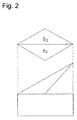
- a midway shape whose base is rhombic formed by two-directional V-shaped grooves passes through the shape asymmetric to right and left shown in FIG. 2 and reflective lateral faces formed of the midway shape include the faces a 2 and b 2 in FIG. 2.
- a midway shape according to the prior art is formed of symmetric V-shaped grooves as shown in FIG. 1, reflective lateral faces to be formed are a pair of faces (faces a 1 and b 1 and faces a 2 and b 2 ).
- optical axes of reflective elements faced each other at the both sides of a V-shaped groove are oriented toward the same direction because of the shape of the assembly.
- the optical axes tilt in the same direction a slight improvement of observation angularity is expected in accordance with spread of reflected light due to variety of types of reflective elements.
- the reflective-element assembly has a very high directivity and thereby, superior entrance angularity is expected in an optical-axis tilting direction.
- the assembly is unavoidably inferior in entrance angularity in other directions.
- the following are requested for a triangular-pyramidal cube-corner retroreflective sheeting as basic optical characteristics: high-brightness characteristics such as height (magnitude) of reflection brightness represented by reflection brightness of light incoming from the front of the sheeting and wide angularity. Moreover, three performances such as observation angularity, entrance angularity, and rotation angularity are requested for wide angularity.
- any retroreflective sheeting constituted of conventionally-publicly-known triangular-pyramidal cube-corner retroreflective elements has a low entrance angularity and does not have observation angularity to be satisfied.
- a retroreflective sheeting constituted of a triangular-pyramidal reflective element in which V-shaped grooves having substantially-symmetric cross sections intersect each other and thereby, a pair of triangular-pyramidal cube-corner retroreflective elements partitioned by three lateral faces (faces a 1 , b 1 , and c 1 ; faces a 2 , b 2 , and c 2 ; ...) are arranged so as to protrude to one side on a common bottom face (S-S') in a closest-packed state, faced lateral faces (faces c 1 and c 2 ) of this pair of triangular-pyramidal retroreflective elements share a base (x) and are paired, the bottom face (S-S') is a common plane including the base (z and z) of one-side lateral faces (faces a 1 and a 2 ) and bases (y and y) of
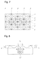
- FIGs. 7 and 8 show a top view and a sectional view for explaining triangular-pyramidal cube-corner retroreflective elements according to a prior art in order to compare the conventional retroreflective elements with triangular-pyramidal cube-corner retroreflective elements of the present invention.
- FIG. 8 shows a pair of reflective elements of the triangular-pyramidal reflective element groups shown in FIG. 7.
- Optical axes (H 1 -Q 1 and H 2 -Q 2 ) of this pair of triangular-pyramidal reflective elements tilt from the vertical plane (Lx-Lx') in directions opposite to each other so that differences between distances (p 1 and p 2 ) from intersections (P 1 and P 2 ) of vertical lines extended from apexes (H 1 and H 2 ) of this pair of elements to a bottom face (S-S') and the base (S-S') up to bases (x,x,...) shared by this pair of elements and distances (q 1 and q 2 ) from intersections (Q 1 and Q 2 ) of the optical axes and the bottom face up to the bases (x,x,...) shared by this pair of elements become plus (+).
- These elements are faced each other as optically analogous shapes rotated by 180° from each other by sharing a base (x) and height
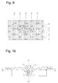
- FIGs. 9 and 10 show a top view and a sectional view for explaining a mode of a triangular-pyramidal cube-corner retroreflective element according to the present invention.
- FIG. 9 shows a triangular-pyramidal cube-corner retroreflective element of the present invention in which a pair of triangular-pyramidal cube-corner retroreflective elements partitioned by three lateral faces (faces a 1 , b 1 , and c 1 ; faces a 2 , b 2 , and c 2 ; ...) almost perpendicularly intersecting each other because V-shaped grooves having substantially-symmetric cross sections intersect each other are arranged in a closest-packed state so as to protrude to one side on a common bottom face (S-S'), faced lateral faces (faces c 1 and c 2 ) of this pair of triangular-pyramidal retroreflective elements share a base (x) and are paired, the bottom face (S-S') is a common plane including bases (z and z) of one-side lateral faces (faces a 1 and a 2 ) of this pair of triangular-pyramidal retrore
- FIG. 10 shows a triangular-pyramidal cube-corner retroreflective sheeting in which, when assuming that the height from a bottom face (Sx-Sx') including bases (x,x,...) shared by faced lateral faces (faces c 1 and c 2 ) of a pair of triangular-pyramidal retroreflective elements (R 1 and R 2 ) up to a apex (H 1 ) of the triangular-pyramidal retroreflective element is hx 1 and the height from a common bottom face (S-S') including bases (z and z) of one-side lateral faces (faces a 1 and a 2 ) of the two triangular-pyramidal retroreflective elements and bases (y and y) of the other-side lateral faces (faces b 1 and b 2 ) of the elements up to the apex (H 1 ) is hyz 1 , hx 1 is larger than hyz 1 and
- a V-shaped groove forming the base (x) is formed so that a height ratio hx 1 /hyz 1 is kept in a range of 1.05 to 1.5, hx 1 becomes larger than hyz 1 , and the above groove becomes deeper than a V-shaped groove forming other bases (y and z).
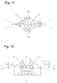
- FIGs. 11 and 12 show enlarged views of a pair of triangular-pyramidal retroreflective elements selected out of the triangular-pyramidal cube-corner retroreflective element groups shown in FIGs. 9 and 10.
- FIGs. 11 and 12 show a pair of triangular-pyramidal cube-corner retroreflective elements in which this pair of triangular-pyramidal cube-corner retroreflective elements partitioned by three lateral faces (faces a 1 , b 1 , and c 1 ; faces a 2 , b 2 , and c 2 ; ...) almost perpendicularly intersecting each other because V-shaped grooves having substantially-symmetric cross sections intersect each other have substantially optically analogous shapes and thereby, have angles ( ⁇ ) formed between substantially same optical axes though different from each other in direction by 180° and a vertical line.
- the pair of triangular-pyramidal cube-corner retroreflective elements shown in FIGs. 11 and 12 particularly have the following features:
- the mode in FIGs. 11 and 12 shows a pair of triangular-pyramidal cube-corner retroreflective elements (R 1 and R 2 ) in which optical axes of this pair of triangular-pyramidal cube-corner retroreflective elements (R 1 and R 2 ) have substantially same tilts ( ⁇ ) though different from each other in direction by 180° and an optical axis (t 1 ) of one-side element (R 1 ) of the triangular-pyramidal reflective element tilts in a direction in which the difference (q 1 -p 1 ) between the distance (q 1 ) from the intersection (Q 1 ) of the optical axis (t 1 ) and the common bottom face (S-S') up to a plane (Lx-Lx') including the base (x) shared by the element pair and vertical to the common bottom face (S-S') and the distance (p 1 ) from the intersection (P 1 ) of a vertical line extended from the apex (H 1
- an optical axis (t 2 ) tilts in a direction in which the difference (q 2 -p 2 ) between the distance (q 2 ) from the intersection (Q 2 ) of the optical axis (t 2 ) and the common bottom face (S-S') up to the plane (Lx-Lx') including the base (x) shared by the element pair and vertical to the common bottom face (S-S') and the distance (p 2 ) from the intersection (P 2 ) of the bottom face (S-S') extended from the apex (H 2 ) of the element to the common bottom face (S-S') and the bottom face (S-S') up to the vertical plane (Lx-Lx') becomes plus (+).
- Optical axes of these elements have substantially same tilt angles ( ⁇ ) though different from each other in direction by 180°.
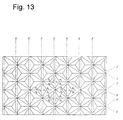
- FIGs. 13 to 15 show a triangular-pyramidal cube-corner retroreflective element that is another mode of the present invention.
- FIGs. 13 to 15 show a triangular-pyramidal cube-corner retroreflective sheeting in which a pair of triangular-pyramidal cube-corner retroreflective elements partitioned by three lateral faces (faces a 1 , b 1 , and c 1 ; faces a 2 , b 2 , and c 2 ; ...) almost perpendicularly intersecting each other because V-shaped grooves having substantially-symmetric cross sections intersect each other have faced lateral faces (faces c 1 and c 2 ) different from each other in shape and heights (hx 1 and hx 2 ) from the common bottom face (S-S') including bases (z and z) of one-side bottom faces (faces a 1 and a 2 ) and bases (y and y) of the other-side lateral faces (faces b 1 and b 2 ) of a pair of retroreflective elements up to apexes (H 1 and H 2 ) are different from each
- FIG. 15 shows a pair of triangular-pyramidal retroreflective elements (R 1 and R 2 ) in which, when assuming that the height from a bottom face (Sx-Sx') including bases (x,x,...) shared by faced lateral faces (faces c 1 and c 2 ) of the triangular-pyramidal retroreflective elements (R 1 and R 2 ) up to a apex (H 1 ) of the triangular-pyramidal retroreflective elements is hx 1 and the height from a common bottom face (S-S') including bases (z and z) of one-side lateral faces (faces a 1 and a 2 ) and bases (y and y) of the other-side lateral faces (faces b 1 and b 2 ) up to the apex (H 1 ) of the two triangular-pyramidal retroreflective elements is hyz 1 , hx 1 is smaller than hyz 1 , and
- each triangular-pyramidal retroreflective element is formed so that a height ratio hx 1 /hyz 1 is kept in a range of 0.67 to 0.95, hx 1 is smaller than hyz 1 , and a V-shaped groove forming the base (x) is shallower than a V-shaped groove forming other bases (y and z).
- FIG. 14 shows a triangular-pyramidal cube-corner retroreflective sheeting in which a pair of triangular-pyramidal cube-corner retroreflective elements partitioned by three lateral faces (faces a 1 , b 1 , and c 1 ; a 2 , b 2 , and c 2 ; ...) almost perpendicularly intersecting each other because V-shaped grooves having substantially-symmetric cross sections intersect each other have substantially optically analogous shapes and thereby, the pair of triangular-pyramidal cube-corner retroreflective elements have angles ( ⁇ ) formed between substantially same optical axes though different from each other in direction by 180° and a vertical line.
- ⁇ angles
- the common base (x) of faced faces (faces c 1 and c 2 ) of a pair of triangular-pyramidal retroreflective elements (R 1 and R 2 ) is formed so as to pass through separate positions (A 2 and B 2 ) without passing through a set of corresponding intersections (A 0 and B 0 ) of a rhombic bottom face (A 0 -C 1 -B 0 -C 2 ) formed by two other bases (y and z) and the distance (offset value) between a line segment (A 0 -B 0 ) and a line segment (A 2 -B 2 ) can be properly selected in a range of ⁇ 2 to ⁇ 20% of the distance between other corresponding intersections (C 1 and C 2 ) of two retroreflective elements (R 1 and R 2 ).
- heights (hx 1 and hx 2 ) from the bottom face (Sx-Sx') up to apexes (H 1 and H 2 ) are different from each other and moreover, two faced lateral faces (c 1 : J 1 -J 2 -K 2 -K 1 -H 1 ) and other lateral face (c 2 : J 2 -H 2 -K 2 ) have shapes different from each other, and the face c 1 of the retroreflective element (R 1 ) becomes larger than the face c 2 of the other retroreflective element (R 2 ).
- a pair of triangular-pyramidal cube-corner retroreflective elements of the present invention have substantially same optical-axis tilts ( ⁇ ) though different from each other in direction by 180° and it is permitted that an optical axis (t 1 ) of one-side element (R 1 ) of the pair of triangular-pyramidal reflective elements tilts in a direction in which the difference (q 1 -p 1 ) between the distance (q 1 ) from the intersection (Q 1 ) of the optical axis (t 1 ) and the common bottom face (S-S') up to a plane (Lx-Lx') including a base (x) shared by the pair of elements and vertical to the common bottom face (S-S') and the distance (p 1 ) from the intersection (P 1 ) of a vertical line extended from a apex (H 1 ) of the elements to the common bottom face (S-S') and the common bottom face (S-S') up to the vertical plane (Lx-L
- These elements have substantially same optical-axis tilts ( ⁇ ) though different from each other in direction by 180°.
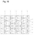
- FIGs. 16 to 18 show a pair of triangular-pyramidal cube-corner retroreflective elements of still another mode of the present invention.
- FIGs. 16 to 18 show a triangular-pyramidal cube-corner retroreflective sheeting in which a pair of triangular-pyramidal cube-corner retroreflective elements partitioned by three lateral faces (faces a 1 , b 1 , and c 1 ; faces a 2 , b 2 , and c 2 ; ...) almost-perpendicularly intersecting each other because V-shaped grooves having substantially-symmetric cross sections intersect each other have faced lateral faces (faces c 1 and c 2 ) different from each other in shape and heights from the common bottom face (S-S') of a pair of retroreflective elements (R 1 and R 2 ) up to apexes (H 1 and H 2 ) of the reflective elements (R 1 and R 2 ) are different from each other.
- S-S' common bottom face
- FIG. 18 shows a pair of triangular-pyramidal retroreflective elements (R 1 and R 2 ) in which, when assuming that the height from a base (Sx-Sx') shared by faced lateral faces (faces c 1 and c 2 ) of the triangular-pyramidal retroreflective elements (R 1 and R 2 ) up to a apex (H 1 ) of the two elements is hx 1 and the height from a common bottom face (S-S') including bases (z and z) of one-side lateral faces (faces a 1 and a 2 ) and bases (y and y) of the other-side lateral faces (faces b 1 and b 2 ) of the two triangular-pyramidal retroreflective elements up to the apex (H 1 ) is hyz 1 , hx 1 is equal to hyz 1 and the height (hx 1 ) from the bottom face (Sx-Sx') up to
- FIG. 17 shows a triangular-pyramidal cube-corner retroreflective sheeting in which a pair of triangular-pyramidal cube-corner retroreflective elements partitioned by lateral faces (faces a 1 , b 1 , and c 1 ; faces a 2 , b 2 , and c 2 ; ...) almost perpendicularly intersecting each other because V-shaped grooves having substantially-symmetric cross sections intersect each other have substantially optically analogous shapes and thereby, this pair of triangular-pyramidal cube-corner retroreflective elements (R 1 and R 2 ) have angles ( ⁇ ) formed between substantially same optical axes though different from each other in direction by 180° and a vertical line.
- a common base (x) of two faced faces (faces c 1 and c 2 ) of two reflective elements is formed so as to pass through positions (A 2 and B 2 ) from a set of corresponding intersections (A 0 and B 0 ) of a rhombic bottom face (A 0 -C 1 -B 0 -C 2 ) formed by two other bases (y and z) without passing through the intersections (A 0 and B 0 ).
- the distance (offset value) between a line segment (A 0 -B 0 ) and a line segment (A 2 -B 2 ) can be properly selected in a range of ⁇ 2 to ⁇ 20% of the distance between two other corresponding intersections (C 1 and C 2 ).
- heights from the common bottom face (S-S') of the two elements (R 1 and R 2 ) up to the apexes (H 1 and H 2 ) are different from each other and two lateral faces (c 1 : A 2 -B 2 -H 1 ) and other lateral face (c 2 : A 2 -H 2 -B 2 ) have shapes and areas different from each other.
- V-shaped grooves forming the common base (x) and other bases (y and z) of faced faces of two elements are formed so that heights hx 1 and hyz 1 are equal to each other. Therefore, other lateral faces (a 1 and b 1 ) of the element (R 1 ) are cut off by V-shaped grooves (y and z) forming lateral faces (a 2 and b 2 ) of other element (R 2 ) and lateral faces (A 0 -A 2 -H 1 and B 0 -B 2 -H 1 ) not contributing to retroreflection may be formed.
- the pair of triangular-pyramidal cube-corner retroreflective elements shown in FIG. 18 have substantially same optical-axis tilts ( ⁇ ) though different from each other in direction by 180° and furthermore, the optical axis (t 1 ) of one-side element (R 1 ) of the pair of triangular-pyramidal reflective elements tilts in a direction in which the difference (q 1 -p 1 ) between the distance from the intersection (Q 1 ) of the optical axis (t 1 ) and the common bottom face (S-S') up to a plane (Lx-Lx') including a base (x) shared by the pair of elements and vertical to the common bottom face (S-S') and the distance (p 1 ) from the intersection (P 1 ) of a vertical line extended from the apex (H 1 ) of the elements to the common bottom face (S-S') and the bottom face (S-S') up to the vertical plane (Lx-Lx') become plus (+).
- the optical axis (t 2 ) of the other element (R 2 ) different from the element (R 1 ) in height tilts in a direction in which the difference (q 2 -p 2 ) between the distance from the intersection (Q 2 ) of the optical axis (t 2 ) and the common bottom face (S-S') up to a plane (Lx-Lx') including a base (x) shared by the elements and vertical to the common bottom face (S-S') and the distance from the intersection (P 2 ) of a vertical line extended from a apex (H 2 ) of the elements and the lane up to the vertical plane (Lx-Lx') becomes plus (+).
- directions of tilt angles of optical axes of these elements are different from each other by 180°, the elements have substantially same optical-axis tilts ( ⁇ ).
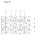
- FIG. 19 shows a triangular-pyramidal cube-corner retroreflective sheeting of still another mode of the present invention.
- FIG. 19 shows a triangular-pyramidal cube-corner retroreflective sheeting in which a pair of triangular-pyramidal cube-corner retroreflective elements partitioned by three lateral faces (faces a 1 , b 1 , and c 1 ; faces a 2 , b 2 , and c 2 ,...) almost perpendicularly intersecting each other because V-shaped grooves having substantially-symmetric cross sections intersect each other are arranged in a closet-packed state so as to protrude to one side on a common bottom face (S-S'), the faced faces (faces c 1 and c 2 ) of this pair of triangular-pyramidal retroreflective elements share a base (x), the common bottom face (S-S') is a common face including bases (z and z) of one-side lateral faces (faces a 1 and a 2 ) and bases (y and y) of the other-side lateral faces (faces b
- bases (x,x,x,... of V-grooves are formed so that they do not match lines (x 0 ,x 0 ,x 0 ,...) passing through a set of corresponding intersections of a rhombic bottom face formed by two other bases (y and z) but they pass through separate positions and distances (offset values) between lines (x 0 ) and bases (x) of V grooves are arranged at right and left of lines (x 0 ,x 0 ,x 0 ,...) every other one of V-shaped grooves (x,x,x,).
- the pitch between one-directional V-shaped grooves (x,x,x%) forming a group of triangular-pyramidal retroreflective elements of the present invention matches the distance between a set of corresponding intersections of a rhombic bottom face (A 0 -C 1 -B 0 -C 2 ) formed by two sets of bases (y and y, and z and z) in two other directions.
- By providing a slight deviation for the pitch between the V-shaped grooves (x,x,x,...) it is possible to provide an offset ⁇ for example, distance between line segment (A 0 ,B 0 ) and line segment (A 2 ,B 2 ) for the base (x) of a V-groove.
- the offset value slowly increases proportionally to the number of V-shaped grooves (x,x,x,%) as cutting of the V-shaped grooves (x,x,x,%) is repeated.
- an opening through which rays pass denotes an other face (element bottom face) enclosed by three lateral faces (faces a 1 , b 1 , and c 1 or faces a 2 , b 2 , and c 2 ) of a triangular pyramid and the area of the face changes proportionally to the height of the element.
- the opening area decreases. Therefore, the spread of reflected light increases as the diffraction effect increases.
- the height of an element becomes 50 ⁇ m or less, spread of reflected light increases.
- excessively small element dimension lowers a retroreflection intensity in the front direction through which light is incoming.
- a triangular-pyramidal retroreflective element of the present invention as shown in FIGs. 9 to 10 and FIGs. 13 to 15, it is possible to obtain a triangular-pyramidal cube-corner retroreflective sheeting in which faced right and left elements are different from each other in height. As a result, it is possible to obtain a new triangular-pyramidal cube-corner retroreflective sheeting in which retroreflective characteristic of rays incoming from right and left are different from each other. Every optical axis of a group of large-height elements arranged at the right side in FIGs.
- FIGs. 9 and 10 tilts rightward and thereby, shows a superior retroreflective characteristic in the right direction and every optical axis of a group of small-height elements arranged at the left side in FIGs. 9 and 10 tilts leftward and thereby, shows superior observation angularity in right and left directions.
- An optical axis (t 1 ) of a pair of triangular-pyramidal retroreflective elements of the present invention tilts in a direction in which the difference (q 1 -p 1 ) between the distance (q 1 ) from the intersection (Q 1 ) of the optical axis (t 1 ) and the bottom face (S-S') of up to a plane (Lx-Lx') including the base (x) shared by the pair of elements and vertical to the common bottom face (S-S') and the distance (p 1 ) from the intersection (P 1 ) of a vertical line extended from a apex (H 1 ) of the elements to the common bottom face (S-S') up to the vertical plane (Lx-Lx') becomes plus (+) or minus (-) so that an angle ( ⁇ ) formed between the optical axis (t 1 ) and the vertical line becomes 0.5 to 12°, preferably 0.6 to 10°, or more preferably 0.6 to 1.5°.
- hx 1 is substantially larger than hyz 1 and thereby, it is possible to increase the area of the face c 1 compared to the faced lateral faces (faces c 1 and c 2 in FIG. 11) of the prior art in which hx 1 is equal to hyz 1 .
- light incoming at an angle almost vertical to the face c 1 in other words, in the case of a large entrance angle, entrance angularity is remarkably improved because the area of the face c 1 is increased.
- improvement of optical characteristics according to increase of the area of the face c 1 is particularly remarkable for a triangular-pyramidal retroreflective element, above all, when the optical axis of the element tilts in a direction in which the difference (q-p) between distances (p) and (q) becomes plus.
- a pair of triangular-pyramidal retroreflective elements of the present invention having a minus tilt are formed so that, when assuming that the height from a bottom face (Sx-Sx') including bases (x,x,x%) shared by faced lateral faces (faces c 1 and c 2 ) of the triangular-pyramidal retroreflective elements up to a apex (H 1 ) of the triangular-pyramidal retroreflective elements is hx 1 and the height from a common bottom face (S-S') including bases (z and z) of one-side lateral faces (faces a 1 and a 2 ) and bases (y and y) of the other-side lateral faces (faces b 1 and b 2 ) of the two triangular-pyramidal retroreflective elements up to the apex (H 1 ) is hyz 1 , hx 1 is substantially smaller than hyz 1 and the ratio hx 1 /h
- hx 1 is substantially smaller than hyz 1 and it is possible to decrease the area of the face c 1 compared to the lateral face c 1 of the prior art in which hx 1 is equal to hyz 1 .
- a cube-corner retroreflective sheeting which has triangular-pyramidal reflective elements in which distances (hx 1 and hx 2 ) from a common bottom face (Sx-Xx') including bases (x,x,...) of triangular-pyramidal cube-corner retroreflective elements protruding beyond the bottom face (Sx-Sx') up to apexes (H 1 and H 2 ) of the triangular-pyramidal reflective elements range between 30 and 400 ⁇ m, more preferably between 50 and 200 ⁇ m, or particularly between 60 and 100 ⁇ m.
- angles formed between three reflective lateral faces (faces a 1 , b 1 , and c 1 or faces a 2 , b 2 , and c 2 ) of a pair of triangular-pyramidal cube-corner retroreflective elements (R 1 and R 2 ) (prism apex angles; a 1 -b 1 -face apex angle, b 1 -c 1 -face apex angle, and c 1 -a 1 -face apex angle, or a 2 -b 2 -face apex angle, b 2 -c 2 -face apex angle, and c 2 -a 2 -face apex angle) are substantially perpendicular to each other.
- angles are not always accurately perpendicular (90.00°) to each other. It is preferable to provide a very slight angular deviation from a right angle for the prism apex angles in order to improve observation angularity. By providing a very-slight angular deviation for the prism apex angles, it is possible to proper diverge the light retroreflected from an obtained triangular-pyramidal cube-corner retroreflective element and improve the observation angularity.
- a method for providing the angular deviation to cut three-directional V-shaped grooves (x, y, and z) forming a triangular-pyramidal cube-corner retroreflective element, it is possible to cut the grooves by right-left-symmetrically providing a slight deviation for the angle of at least one-directional V-shaped groove from an angle for a prism apex angle to form a right angle.
- the method for providing a deviation is achieved by using a right-left-symmetric cutting tool.
- the angle of a V-shaped groove so that at least one prism apex angle is slightly deviated from 90.00° in a range of ⁇ (0.01° to 0.4°) or preferably in a range of ⁇ (0.001° to 0.2°).
- a triangular-pyramidal cube-corner retroreflective sheeting of the present invention by forming the sheeting into a concave shape in which the shape of the above-described triangular-pyramidal reflective element is inverted, using cube-corner molding dies arranged on a metallic belt in a closest-packed state, heating and pressing a flexible proper resin sheeting superior in optical transparency and uniformity against the molding dies, and inversely transferring the shape of the dies to the resin sheeting.
- a typical manufacturing method of the cube-corner molding die is disclosed in, for example, the Stamm's US Pat. No. 3,712,706 in detail and the present invention can also use a method according to the above method.
- a matrix of a microprism is formed by using a hard cutting tool (e.g. diamond cutting tool or tungsten-carbide cutting tool) having a tip angle of approx. 73.4 to 81.0°, thereby determining each-directional repetitive pitch, groove depths (e.g.
- crossing angle a supplementary angle of the crossing angle between y- and z-directions (in this case, more-acute angle is referred to as "crossing angle") without passing through the intersection of y- and z-directional formed grooves.
- it is permitted to set the depths (hx 1 and hx 2 ) of x-directional grooves to values equal to the depths (hyz 1 and hyz 2 ) of y- and z-directional grooves.
- a repetitive pitch in y and z directions ranges between 100 and 810 ⁇ m
- groove depths (hyz 1 and hyz 2 ) range between 50 and 400 ⁇ m
- a crossing angle ranges between 43 and 45°
- x-directional groove depths (hx 1 and hx 2 ) range between 75 and 600 ⁇ m.
- a metal having a Vickers hardness JIS Z 22464 of 350 or more or particularly preferably, a Vickers hardness of 380 or more as the base material of the matrix of the microprism.
- the following metals can be listed: amorphous copper, electrodeposited nickel, and aluminum.
- alloy-based materials the following materials can be listed: copper-zinc alloy (brass), copper-tin-zinc alloy, nickel-cobalt alloy, nickel-zinc alloy, and aluminum alloy.
- the above base material can use a synthetic resin.
- a synthetic resin having a glass transition temperature of 150°C or higher, particularly 200°C or higher and a Rockwell hardness (JIS Z2245) of 70 or more, particularly 75 or more because a trouble does not easily occur that the resin is softened in cutting and thereby, it is difficult to cut the resin.
- one of the following materials can be use: polyethylene-terephthalate-based resin, polybutylene-phthalate-based resin, polycarbonate-based resin, polymethyl-methacrylate-based resin, polyimide-based resin, polyarylate-based resin, polyether-sulfone-based resin, polyether-imide-based resin, and cellulose-triacetate-based resin.
- a metallic film is formed on the obtained microprism matrix by electroforming the surface of the matrix.
- Electroforming is generally performed in, for example, an aqueous solution of containing 60 wt% of sulfamic acid at approx. 40°C and a current condition of approx. 10 A/dm 2 .
- a uniform electroformed layer can be easily obtained by setting an electroformed-layer forming rate to, for example, 0.02 mm/hr or less. In the case of a forming rate higher than 0.02 mm/hr, a trouble easily occurs that smoothness of the surface is lost or a deficient portion occurs in an electroformed layer.
- a first-generation electroforming die manufactured from the prism matrix can be repeatedly used as an electroforming master used to manufacture a second-generation electroforming die. Therefore, it is possible to manufacture a plurality of electroforming dies from one prism matrix.
- a plurality of manufactured electroforming dies are precisely cut and then, used by combining and joining them up to the final die size for molding a microprism sheeting made of a synthetic resin.
- This joining method can use a method of simply butting cut ends or a method of welding a combined joint through electron-beam welding, YAG laser welding, or carbon-dioxide-gas laser welding.
- a combined electroforming die is used to mold a synthetic resin as a synthetic-resin molding die.
- the synthetic-resin molding method can use compression molding or injection molding.
- Compression molding can be performed by inserting a formed thin-wall nickel electroforming die, a synthetic-resin sheeting having a predetermined thickness, and a silicone-rubber sheeting having a thickness of approx. 5 mm serving as a cushion material into a compression-molding press heated at a predetermined temperature, preheating them for 30 sec at a pressure of 10 to 20% of a molding pressure, then heating and pressing them for approx. 2 min at 180 to 250°C and 10 to 30 kg/cm 2 . Thereafter, a molded prism can be obtained by cooling them up to room temperature and releasing the pressure.
- a continuous sheeting-like product can be obtained by joining a thin-wall electroforming die having a thickness of approx. 0.5 mm formed through the above method to make an endless-belt die, setting and rotating the belt die to and on a pair of rollers comprising a heating roller and a cooling roller, supplying melted synthetic resin to the belt die on the heated roller in the form of a sheeting, pressuring and molding the sheeting by one silicone roller or more, then cooling the molded sheeting on a cooling roller to a transition temperature or lower, and removing the molded sheeting from the belt die.
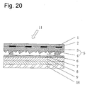
- FIG. 20 showing a sectional view of the mode.
- symbol 1 denotes a surface protective layer
- 2 denotes a printed layer
- 3 denotes a holding-body layer for holding the reflective elements
- 4 denotes a reflective-element layer
- 5 denotes a support layer and a reflective-element layer
- 6 denotes an air layer
- 7 denotes a binder layer
- 8 denotes a support layer
- 9 denotes an adhesive layer
- 10 denotes a separating-material layer
- 11 denotes an entrance light
- 12 denotes a mirror reflection layer.
- symbol 4 denotes a reflective-element layer on which triangular-pyramidal reflective elements (R 1 and R 2 ) of the present invention are arranged in a closest-packed state
- 3 denotes a holding-body layer for holding the reflective elements
- 11 denotes a light incoming direction.
- the reflective-element layer (4) and holding-body layer (3) are normally united into one body (5). However, it is also permitted to superimpose the layers (4) and (3) each other.
- a surface protective layer (1) for communicating information to an observer or coloring the sheeting
- a binder layer (7) for achieving a sealing structure for preventing moisture from entering the back of a reflective-element layer
- a support layer (8) for supporting the binder layer (7)
- an adhesive layer (9) and a releasing-liner layer (10) for bonding the retroreflective sheeting to other structure.
- any material can be used to constitute the reflective-element layer (4) and holding-body layer (3) as long as the material meets flexibility that is an object of the present invention.
- a material having optical transparency and uniformity As materials usable for the present invention, the following can be listed: polycarbonate resin, vinyl chloride resin, (meth)acrylate resin, epoxy resin, styrene resin, polyester resin, fluorine resin, olefin resin such as polyethylene resin or polypropylene resin, cellulose-based resin, and urethane resin.
- ultraviolet absorber, light stabilizer, and antioxidant independently or by combining them in order to improve weatherbility.
- the surface protective layer (1) can use the resin same as that used for the retroreflective-element layer (4). However, in order to improve weather resistance, it is possible to use ultraviolet absorbent, light stabilizer, and antioxidant independently or by combining them. Moreover, it is possible to contain various organic pigments, inorganic pigments, fluorescent pigments, dyes, and fluorescent dyes in the resin as colorants.
- the reflective-element layer (4) of the present invention it is general to set an air layer (6) on the back of a cube-corner retroreflective element in order to increase a critical angle meeting an internal total reflection condition.
- the reflective-element layer (4) and support layer (8) are sealed by the binder layer (7).
- the sealing method can use one of the methods disclosed in US Pat. Nos. 3,190,178, 4,025,159, and Japanese Utility Model Laid-Open No. 28,669/1975.
- the binder layer (7) can use one of (meth)acrylate resin, polyester resin, alkyd resin, and epoxy resin.
- the joining method can properly use one of publicly-known thermally-fusing-resin joining method, thermosetting-resin joining method, ultraviolet-curing-resin joining method, and electron-beam-curing-resin joining method.
- binder layer (7) used for the present invention on the entire surface of the support layer (8) or selectively set the layer (7) to a joint with a retroreflective-element layer through a method such as printing method.
- the support layer (8) As a material constituting the support layer (8), it is possible to use a resin constituting a retroreflective-element layer, a general resin which can be formed into a film, fiber, cloth, and metallic foil or plate of stainless steel or aluminum independently or by combining them.
- the above adhesive can use one of a pressure-sensitive adhesive, heat-sensitive adhesive, and cross-linking adhesive.
- the pressure-sensitive adhesive can use one of polyacrylic ester adhesive obtained by copolymerizing butyl acrylate, 2-ethylhexyl acrylate, isooctyl acrylate, or nonyl acrylate with acrylic acid or vinyl acetate, silicon-resin-based adhesive, and rubber-based adhesive.
- FIG. 21 showing a sectional view of the mode.
- a metallic mirror-reflection layer (12) is set to the surface of a reflective element (4) and moreover, an adhesive layer and a separating-material layer are directly brought into contact with the mirror-reflection layer (12) and superimposed.
- the cube-corner retroreflective sheeting of this mode does not require an air layer because it retroreflects light in accordance with the mirror reflection theory and therefore, it does not require a binder layer or support layer.
- a triangular-pyramidal cube-corner retroreflective sheeting of the present invention allows the mirror reflection layer (12) made of a metal such as aluminum, copper, silver, or nickel to be formed on the surface of the reflective element (4) by means of vacuum deposition, chemical plating, or sputtering.
- a vacuum deposition method using aluminum is preferable because it is possible to lower a vacuum-deposition temperature and thereby, minimize thermal deformation of a retroreflective element in the vacuum-deposition step, and moreover, brightness of color tone of the mirror reflection layer (12) is maximized.
- a continuous vacuum-deposition system for the aluminum mirror reflection layer (12) comprises a vacuum vessel capable of keeping a vacuum degree at approx. 7-9 ⁇ 10 -4 mmHg, an unwinder for unwinding a prism original sheeting constituted of two layers such as a substrate sheeting set in the vacuum vessel and a surface protective layer superimposed on the surface of the substrate sheeting at the light-incoming side, a winder for winding the vacuum-deposited prism original sheeting, and a heater capable of fusing aluminum by an electric heater in a graphite crucible.
- Pure aluminum pellets having a purity of 99.99 wt% or more are put into the graphite crucible and fused at an AC voltage of 350 to 360 V, a current of 115 to 120 A, and a treatment rate of 30 to 70 m/min, and the mirror reflection layer (12) on the surface of the retroreflective element can be vacuum-deposited by aluminum atoms at a thickness of, for example, 800 to 2000 ⁇ .
- V-shaped parallel grooves whose y- and z-directional sectional forms are symmetric are cut on a 100-mm-square brass plate whose surface is smoothly cut in a repetitive pattern through the fly-cutting method by using a diamond cutting tool having a tip angle of 71.52° so that a repetitive pitch between y-and z-directional V-shaped grooves becomes 210.88 ⁇ m, the depth of a V-shaped groove becomes 100 ⁇ m, and the crossing angle between the y- and z-directional V-shaped grooves becomes 58.76°.
- x-directional V-shaped parallel grooves whose x-directional sectional forms are symmetric are cut in a repetitive pattern by using a diamond cutting tool having a tip angle of 68.53° so that the repetitive pitch between y- and z-directional V-shaped grooves becomes 214.92 ⁇ m, the depth of a V-shaped groove becomes 115 ⁇ m, and an offset value from a line connecting two intersections between y- and z-directional grooves in parallel with the line becomes 11 ⁇ m to form a matrix in which a plurality of convex triangular-pyramidal cube-corner element groups are arranged in a closest-packed state on a brass plate.
- a height (hx 1 ) from an apex (H 1 ) up to a bottom plane (Sx-Sx') is 115 ⁇ m
- a height (hx 2 ) from an apex (H 2 ) up to the bottom plane (Sx-Sx') is 100 ⁇ m
- a height (hyz 1 ) from the apex (H 1 ) up to the bottom plane (S-S') is 100 ⁇ m
- a height (hyz 2 ) from the apex (H 2 ) up to the bottom plane (S-S') is 85 ⁇ m.
- optical-axis tilt angles ( ⁇ ) of the triangular-pyramidal retroreflective elements are respectively equal to +1° and prism angles of three lateral faces constituting a reflective element are respectively equal to 90°.
- an inverted concave cube-corner molding die made of nickel is manufactured through the electroforming method.
- a polycarbonate-resin sheeting having a thickness of 200 ⁇ m (“Iupilon Sheet H3000" made by Mitsubishi Engineering-Plastics Corp.) is compression-molded at a molding temperature of 200°C and a molding pressure of 50 kg/cm 2 by using the above molding die and then, cooled up to 30°C under the pressure, then, taken out to form a polycarbonate-resin triangular-pyramidal cube-corner retroreflective sheeting on which surface a plurality of triangular-pyramidal retroreflective elements are arranged in a closest-packed state.
- many groups of V-shaped parallel grooves whose y- and z-directional sectional forms are symmetric are cut in a repetitive pattern through the fly-cutting method so that a repetitive pitch between y- and z-directional V-shaped grooves becomes 164.18 ⁇ m, the depth of a V-shaped groove becomes 80 ⁇ m, and the crossing angle between the y- and z-directional V-shaped grooves becomes 50.68°.
- x-directional V-shaped parallel grooves whose x-directional sectional forms are symmetric are cut in a repetitive pattern by using a diamond cutting tool having a tip angle of 64.66° so that the repetitive pitch between y- and z-directional V-shaped grooves becomes 191.84 ⁇ m, the depth of a V-shaped groove becomes 92 ⁇ m, and an offset value from a line connecting two intersections between y- and z-directional grooves in parallel with the line becomes 10 ⁇ m to form a matrix in which a plurality of convex triangular-pyramidal cube-corner element groups are arranged in a closest-packed state on a brass plate.
- a height (hx 1 ) from an apex (H 1 ) up to a bottom plane (Sx-Sx') is 92 ⁇ m
- a height (hx 2 ) from an apex (H 2 ) up to the bottom plane (Sx-Sx') is 80 ⁇ m
- a height (hyz 1 ) from the apex (H 1 ) up to the bottom plane (S-S') is 80 ⁇ m
- a height (hyz 2 ) from the apex (H 2 ) up to the bottom plane (S-S') is 68 ⁇ m
- optical-axis tilt angles ( ⁇ ) of the triangular-pyramidal retroreflective elements are respectively equal to +8° and prism angles of three lateral faces constituting a reflective element are respectively equal to 90°.
- a triangular-pyramidal cube-corner retroreflective sheeting made of polycarbonate resin are formed on which many triangular-pyramidal retroreflective elements whose support layer has a thickness of approx. 150 ⁇ m are arranged in a closest-packed state.
- many groups of V-shaped parallel grooves whose y- and z-directional sectional forms are symmetric are cut in a repetitive pattern through the fly-cutting method so that a repetitive pitch between y- and z-directional V-shaped grooves becomes 218.2 ⁇ m, the depth of a V-shaped groove becomes 110 ⁇ m, and the crossing angle between the y- and z-directional V-shaped grooves becomes 64.66°.
- x-directional V-shaped parallel grooves whose x-directional sectional forms are symmetric are cut in a repetitive pattern by using a diamond cutting tool having a tip angle of 78.53° so that the repetitive pitch between y- and z-directional V-shaped grooves becomes 204.08 ⁇ m, the depth of a V-shaped groove becomes 100 ⁇ m, and an offset value from a line connecting two intersections between y- and z-directional grooves in parallel with the line becomes 10 ⁇ m to form a matrix in which a plurality of convex triangular-pyramidal cube-corner element groups are arranged in a closest-packed state on a brass plate.
- a height (hx 1 ) from an apex (H 1 ) up to a bottom plane (Sx-Sx') is 100 ⁇ m
- a height (hx 2 ) from an apex (H 2 ) up to the bottom plane (Sx-Sx') is 110 ⁇ m
- a height (hyz 1 ) from the apex (H 1 ) up to the bottom plane (S-S') is 100 ⁇ m
- a height (hyz 2 ) from the apex (H 2 ) up to the bottom plane (S-S') is 90 ⁇ m
- optical-axis tilt angles ( ⁇ ) of the triangular-pyramidal retroreflective elements are respectively equal to -8° and prism angles of three lateral faces constituting a reflective element are respectively equal to 90°.
- a triangular-pyramidal cube-corner retroreflective sheeting made of polycarbonate resin is formed on which many triangular-pyramidal retroreflective elements whose support layer has a thickness of approx. 150 ⁇ m are arranged in a closest-packed state.
- many groups of V-shaped parallel grooves whose y- and z-directional sectional forms are symmetric are cut in a repetitive pattern through the fly-cutting method so that a repetitive pitch between y- and z-directional V-shaped grooves becomes 210.88 ⁇ m, the depth of a V-shaped groove becomes 100 ⁇ m, and the crossing angle between the y- and z-directional V-shaped grooves becomes 58.76°.
- an x-directional V-shaped parallel groove group having a V-shaped-groove repetitive pitch of 214.92 ⁇ m, and a V-shaped-groove depth of 100 ⁇ m is cut in a repetitive pattern by using a diamond cutting tool having a tip angle of 68.53° to form a matrix in which many convex triangular-pyramidal cube-corner element groups are arranged in a closest state on a brass plate.
- heights (hx 1 and hx 2 ) from apexes (H 1 and H 2 ) up to a bottom plane (Sx-Sx') are 100 ⁇ m and heights (hyz 1 and hyz 2 ) from the apexes (H 1 and H 2 ) up to the bottom plane (S-S') are also 100 ⁇ m.
- Optical-axis tilt angles ( ⁇ ) of the triangular-pyramidal retroreflective elements are respectively equal to +1° and prism angles of three lateral faces constituting a reflective element are respectively equal to 90°.
- a triangular-pyramidal cube-corner retroreflective sheeting made of polycarbonate resin is formed on which many triangular-pyramidal retroreflective elements whose support layer has a thickness of approx. 150 ⁇ m are arranged in a closest-packed state.
- many groups of V-shaped parallel grooves whose y- and z-directional sectional forms are symmetric are cut in a repetitive pattern through the fly-cutting method so that a repetitive pitch between y- and z-directional V-shaped grooves becomes 218.28 ⁇ m, the depth of a V-shaped groove becomes 100 ⁇ m, and the crossing angle between the y- and z-directional V-shaped grooves becomes 64.66°.
- an x-directional V-shaped parallel groove group having a V-shaped-groove repetitive pitch of 204.08 ⁇ m, and a V-shaped-groove depth of 100 ⁇ m is cut in a repetitive pattern by using a diamond cutting tool having a tip angle of 78.53° to form a matrix in which many convex triangular-pyramidal cube-corner element groups are arranged in a closest state on a brass plate.
- heights (hx 1 and hx 2 ) from apexes (H 1 and H 2 ) up to a bottom plane (Sx-Sx') are 100 ⁇ m and heights (hyz 1 and hyz 2 ) from the apexes (H 1 and H 2 ) up to the bottom plane (S-S') are also 100 ⁇ m.
- Optical-axis tilt angles ( ⁇ ) of the triangular-pyramidal retroreflective elements are respectively equal to -4° and prism angles of three lateral faces constituting a reflective element are respectively equal to 90°.
- a triangular-pyramidal cube-corner retroreflective sheeting made of polycarbonate resin is formed on which many triangular-pyramidal retroreflective elements whose support layer has a thickness of approx. 150 ⁇ m are arranged in a closest-packed state.
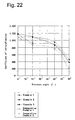
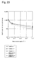
- First table shows values obtained by measuring coefficients of retroreflection of the triangular-pyramidal cube-corner retroreflective sheetings formed for the above embodiments 1 to 3 and comparative examples 1 and 2 (unit of reflectivity is cd/lx * m 2 ).
- the coefficients of retroreflection were measured in accordance with the measuring method specified by Retroreflectors-Optical Properties-Measuring method specified in JIS Z8714-1995 by setting combinations of observation angles and entrance angles to 0.2°/5°, 0.2°/15°, 0.2°/30°, 0.33°/5°, and 1.0°/5°.
- FIG. 22 shows the relation between entrance angles and retrorefletction coefficients at the entrance angles by assigning the entrance angle to x-axis and the coefficient of retroreflection at each entrance angle to y-axis.
- FIG. 23 shows the relation between observation angles and retrorefletction coefficients at the entrance angles by assigning the observation angle to x-axis and the coefficient of retroreflection at each entrance angle to y-axis which is a logarithmic axis.
- coefficients of retroreflection are remarkably improved at a large entrance angle, particularly at an entrance angle of 40° and moreover, coefficients of retroreflection are remarkably improved at a large observation angle.
- the triangular-pyramidal cube-corner retroreflective sheeting of the prior art formed for the comparative example 1 or 2 brightness is remarkably lowered at an entrance angle of 40° or an observation angle of 1.0°.
Landscapes
- Physics & Mathematics (AREA)
- General Physics & Mathematics (AREA)
- Optics & Photonics (AREA)
- Optical Elements Other Than Lenses (AREA)
- Lighting Device Outwards From Vehicle And Optical Signal (AREA)
Applications Claiming Priority (2)
| Application Number | Priority Date | Filing Date | Title |
|---|---|---|---|
| JP2000072279A JP3468418B2 (ja) | 2000-03-15 | 2000-03-15 | 三角錐型キユーブコーナー型再帰反射シート |
| JP2000072279 | 2000-03-15 |
Publications (4)
| Publication Number | Publication Date |
|---|---|
| EP1136847A2 true EP1136847A2 (de) | 2001-09-26 |
| EP1136847A3 EP1136847A3 (de) | 2002-06-12 |
| EP1136847B1 EP1136847B1 (de) | 2005-07-06 |
| EP1136847B8 EP1136847B8 (de) | 2005-10-19 |
Family
ID=18590719
Family Applications (1)
| Application Number | Title | Priority Date | Filing Date |
|---|---|---|---|
| EP00107190A Expired - Lifetime EP1136847B8 (de) | 2000-03-15 | 2000-04-12 | Retroreflektierende Folie mit dreieck-pyramidischen Würfelecken |
Country Status (7)
| Country | Link |
|---|---|
| US (4) | US6318866B1 (de) |
| EP (1) | EP1136847B8 (de) |
| JP (1) | JP3468418B2 (de) |
| CN (1) | CN1265214C (de) |
| CA (1) | CA2340599C (de) |
| DE (1) | DE60021165T2 (de) |
| HK (1) | HK1041051B (de) |
Cited By (4)
| Publication number | Priority date | Publication date | Assignee | Title |
|---|---|---|---|---|
| WO2004006216A1 (ja) * | 2002-07-08 | 2004-01-15 | Nippon Carbide Kogyo Kabushiki Kaisha | 内部照明標識 |
| US7314284B2 (en) | 2003-12-17 | 2008-01-01 | Kaneka Corporation | Retroreflection sheeting and film for use in retroreflection sheeting |
| KR100968103B1 (ko) * | 2002-07-08 | 2010-07-06 | 닛뽕 카바이도 고교 가부시키가이샤 | 내부 조명 표지 |
| CN101506694B (zh) * | 2006-08-22 | 2012-10-03 | 日本电石工业株式会社 | 三棱锥型立方角回射部件及其制造方法 |
Families Citing this family (43)
| Publication number | Priority date | Publication date | Assignee | Title |
|---|---|---|---|---|
| EP1424572B1 (de) * | 2001-08-09 | 2006-10-04 | Nippon Carbide Kogyo Kabushiki Kaisha | Retroreflexionseinrichtung |
| DE10216579A1 (de) * | 2002-04-14 | 2003-10-23 | Sen Hans-Erich Gubela | Weitwinkelsensorsystem mit Tripelreflektor und Herstellung der Werkzeuge |
| JP3890005B2 (ja) * | 2002-10-16 | 2007-03-07 | 古河電気工業株式会社 | 光反射板およびその製造方法 |
| US6902280B2 (en) * | 2002-12-17 | 2005-06-07 | Avery Dennison Corporation | Tri-level cube corner ruling |
| EP1623253A1 (de) | 2003-03-06 | 2006-02-08 | 3M Innovative Properties Company | Lamina mit würfeleckenelementen und retroreflektiven folien |
| US7156527B2 (en) | 2003-03-06 | 2007-01-02 | 3M Innovative Properties Company | Lamina comprising cube corner elements and retroreflective sheeting |
| NL1023737C2 (nl) * | 2003-06-24 | 2004-12-28 | Klaus Herbert Gunter Wenger | Lichtverdelende optische folie. |
| US7201485B1 (en) | 2003-08-15 | 2007-04-10 | University Of South Florida | Corner cube retroreflector |
| JP4152861B2 (ja) * | 2003-10-27 | 2008-09-17 | シャープ株式会社 | コーナーキューブリフレクタ、その製造方法及びそれを用いた反射型表示装置 |
| WO2005054909A1 (ja) | 2003-12-02 | 2005-06-16 | Nippon Carbide Kogyo Kabushiki Kaisha | 湾曲した反射側面を持つ三角錐型キューブコーナー再帰反射物品 |
| CN100445777C (zh) * | 2003-12-02 | 2008-12-24 | 日本电石工业株式会社 | 具有弯曲的反射侧面的三棱锥型立体角回复反射物品 |
| JP5009491B2 (ja) * | 2004-05-11 | 2012-08-22 | 出光興産株式会社 | 液晶バックライト装置用プリズム一体型光拡散板 |
| US20060101977A1 (en) * | 2004-11-15 | 2006-05-18 | Namiki Seimitsu Houseki Kabushiki Kaisha | Diamond scriber |
| JP4800302B2 (ja) | 2005-04-11 | 2011-10-26 | 日本カーバイド工業株式会社 | 印刷像が設置されている再帰反射シート |
| US7905611B1 (en) * | 2006-04-17 | 2011-03-15 | Bourget Anthony J | Vehicle having underside reflector |
| EP2023167B1 (de) * | 2006-06-06 | 2013-11-27 | Nippon Carbide Kogyo Kabushiki Kaisha | Würfelecken-rückstrahlartikel |
| CN101420829B (zh) * | 2007-10-25 | 2011-09-21 | 深圳富泰宏精密工业有限公司 | 金属外壳及其制作方法 |
| CN101456667B (zh) * | 2007-12-10 | 2011-12-21 | 鸿富锦精密工业(深圳)有限公司 | 棱镜片的制造方法 |
| KR100970741B1 (ko) * | 2008-02-04 | 2010-07-16 | 이강훈 | 광 파이프 |
| WO2010067583A1 (ja) | 2008-12-08 | 2010-06-17 | 日本カーバイド工業株式会社 | 再帰反射物品 |
| AU2010248533B2 (en) | 2009-05-11 | 2013-08-29 | Nippon Carbide Industries Co., Inc. | Hexagonal corner cube retroreflective article |
| WO2011053419A2 (en) * | 2009-09-29 | 2011-05-05 | 3M Innovative Properties Company | Optically transmissive substrate having a fiducial mark and methods of aligning optically transmissive substrates |
| GB201117058D0 (en) * | 2011-10-04 | 2011-11-16 | Qinetiq Ltd | Infrared transparent film |
| US8783880B2 (en) * | 2011-11-01 | 2014-07-22 | Avery Dennison Corporation | Rulable multi-directional prism cluster retroreflective sheeting |
| KR101896935B1 (ko) * | 2011-12-22 | 2018-09-12 | 엘지이노텍 주식회사 | 휘도 및 내구성 향상을 위한 재귀반사구조체 및 그 형성 방법 |
| US20140169968A1 (en) * | 2012-12-13 | 2014-06-19 | General Electric Company | Collision avoidance system for a wind turbine |
| CN104884237A (zh) * | 2013-02-11 | 2015-09-02 | 奥丽福美洲公司 | 立体角锥反射器及其方法 |
| DE102013110344B4 (de) * | 2013-09-19 | 2022-09-01 | HELLA GmbH & Co. KGaA | Beleuchtungsvorrichtung für Fahrzeuge zur Erzeugung von Schlusslicht- und Nebelschlusslichtfunktionen |
| US10330943B2 (en) | 2015-06-12 | 2019-06-25 | Nippon Carbide Industries Co., Inc. | Image display device |
| WO2017156448A1 (en) * | 2016-03-11 | 2017-09-14 | Mirraviz, Inc. | Customized reflection profiles for retro-reflective display system optimization |
| EP3594015A4 (de) | 2017-03-06 | 2020-07-08 | LG Chem, Ltd. | Zierelement und verfahren zur herstellung eines zierelements |
| KR101966851B1 (ko) | 2017-03-06 | 2019-04-08 | 주식회사 엘지화학 | 장식 부재 및 이의 제조방법 |
| TWI756466B (zh) * | 2017-08-29 | 2022-03-01 | 美商艾維利 丹尼森公司 | 用於基於投影機的顯示系統的回射片 |
| CN107561612A (zh) * | 2017-10-17 | 2018-01-09 | 张家港康得新光电材料有限公司 | 反光膜及其应用以及栅线结构和太阳能面板 |
| DE102018207452B4 (de) * | 2018-05-15 | 2025-03-13 | Audi Ag | Reflektor für ein Fahrzeug zur Darstellung zumindest eines Symbols, Fahrzeug sowie Herstellungsverfahren |
| US11001979B2 (en) | 2018-08-13 | 2021-05-11 | Vergence Automation, Inc. | Methods and apparatus for ultrawide entrance angle reflective articles for use with autonomous vehicle machine vision systems |
| US11762133B1 (en) | 2018-09-13 | 2023-09-19 | Vergence Automation, Inc. | Retroreflective materials and articles incorporating near-ideal total internal retroreflective elements |
| CN109965460B (zh) * | 2019-04-10 | 2022-02-22 | 海宁市金潮实业有限公司 | 一种反光挂扣及篷布 |
| WO2022046134A1 (en) | 2020-08-27 | 2022-03-03 | Aura Optical System, LP | Microprismatic retroreflective mold, sheet, and article and methods of manufacture thereof |
| JP2024130375A (ja) | 2023-03-14 | 2024-09-30 | マクセル株式会社 | 空中浮遊映像表示装置およびキャラクター表示装置 |
| JP2024131889A (ja) | 2023-03-16 | 2024-09-30 | マクセル株式会社 | 空中浮遊映像表示装置およびキャラクター表示装置 |
| CN118759624B (zh) * | 2024-09-06 | 2024-11-15 | 泉州师范学院 | 双三棱锥组合结构的微棱镜反光膜及其模具的制造方法 |
| WO2026051778A1 (zh) * | 2024-09-06 | 2026-03-12 | 泉州师范学院 | 三棱锥组合结构的微棱镜反光膜及其模具制造方法 |
Family Cites Families (46)
| Publication number | Priority date | Publication date | Assignee | Title |
|---|---|---|---|---|
| US2310790A (en) | 1943-02-09 | Optical reflecting material | ||
| US2380447A (en) | 1945-07-31 | Optical reflecting material | ||
| GB441319A (en) | 1933-12-21 | 1936-01-16 | Gustave Leray | Improvements in or relating to light reflectors |
| US2481757A (en) | 1945-05-23 | 1949-09-13 | Thoger G Jungersen | Optical reflecting material |
| US3190178A (en) * | 1961-06-29 | 1965-06-22 | Minnesota Mining & Mfg | Reflex-reflecting sheeting |
| US3712706A (en) | 1971-01-04 | 1973-01-23 | American Cyanamid Co | Retroreflective surface |
| US3830682A (en) * | 1972-11-06 | 1974-08-20 | Rowland Dev Corp | Retroreflecting signs and the like with novel day-night coloration |
| USRE29396E (en) | 1975-02-18 | 1977-09-13 | Amerace Corporation | Pin having nonaligned cube axis and pin axis and bundle of such pins |
| US4025159A (en) | 1976-02-17 | 1977-05-24 | Minnesota Mining And Manufacturing Company | Cellular retroreflective sheeting |
| US4349598A (en) | 1976-12-01 | 1982-09-14 | Minnesota Mining And Manufacturing Company | High incidence angle retroreflective material |
| US4498733A (en) * | 1982-07-02 | 1985-02-12 | Amerace Corporation | Reflector structure |
| AU560276B2 (en) | 1983-09-12 | 1987-04-02 | Minnesota Mining And Manufacturing Company | Cube-corner retroreflective articles |
| US4588258A (en) | 1983-09-12 | 1986-05-13 | Minnesota Mining And Manufacturing Company | Cube-corner retroreflective articles having wide angularity in multiple viewing planes |
| MX169129B (es) | 1984-08-10 | 1993-06-22 | Amerace Corp | Metodo para producir construcciones de lamina de estructura laminada retrorreflejante del tipo de esquinas de cubo y el producto obtenido con el mismo. |
| US5064272A (en) | 1985-11-18 | 1991-11-12 | Minnesota Mining And Manufacturing Company | Encapsulated-lens retroreflective sheeting and method of making |
| US4897136A (en) | 1985-11-18 | 1990-01-30 | Minnesota Mining And Manufacturing Company | Method of making encapsulated-lens retroreflective sheeting |
| US4775219A (en) * | 1986-11-21 | 1988-10-04 | Minnesota Mining & Manufacturing Company | Cube-corner retroreflective articles having tailored divergence profiles |
| US4801193A (en) * | 1988-03-04 | 1989-01-31 | Reflexite Corporation | Retroreflective sheet material and method of making same |
| US5264063A (en) * | 1990-05-16 | 1993-11-23 | Reflexite Corporation | Method for making flexible retroreflective sheet material |
| US5138488A (en) | 1990-09-10 | 1992-08-11 | Minnesota Mining And Manufacturing Company | Retroreflective material with improved angularity |
| DE4242264C2 (de) | 1992-12-15 | 1994-09-22 | Gubela Sen Hans Erich | Körper oder Bauteil mit einer Mikrodoppeltripel aufweisenden Oberfläche sowie Verfahren zur Herstellung eines derartigen Körpers oder Bauteils |
| US5376431A (en) * | 1993-05-12 | 1994-12-27 | Reflexite Corporation | Retroreflective microprism sheeting with silver/copper reflecting coating and method of making same |
| US5450235A (en) * | 1993-10-20 | 1995-09-12 | Minnesota Mining And Manufacturing Company | Flexible cube-corner retroreflective sheeting |
| US5600484A (en) | 1993-10-20 | 1997-02-04 | Minnesota Mining And Manufacturing Company | Machining techniques for retroreflective cube corner article and method of manufacture |
| CN1040691C (zh) * | 1993-10-20 | 1998-11-11 | 美国3M公司 | 直接机加工凸出结构后向反射立方隅角制品及其制造方法 |
| JP3834596B2 (ja) | 1993-10-20 | 2006-10-18 | スリーエム カンパニー | 非対称性コーナキューブ物品と製作方法 |
| US5557836A (en) | 1993-10-20 | 1996-09-24 | Minnesota Mining And Manufacturing Company | Method of manufacturing a cube corner article |
| US5565151A (en) * | 1994-09-28 | 1996-10-15 | Reflexite Corporation | Retroreflective prism structure with windows formed thereon |
| US6206525B1 (en) * | 1994-09-28 | 2001-03-27 | Reflexite Corporation | Miniature micro prism retroreflector |
| DE69509670T2 (de) * | 1994-09-28 | 1999-11-18 | Reflexite Corp., Avon | Retroreflektive geneigte prismenstruktur |
| US6258443B1 (en) * | 1994-09-28 | 2001-07-10 | Reflexite Corporation | Textured retroreflective prism structures and molds for forming same |
| AU698459B2 (en) * | 1995-06-09 | 1998-10-29 | Minnesota Mining And Manufacturing Company | Retroreflective cube corner article having scalene base triangles |
| EP0844056B1 (de) * | 1995-07-28 | 2003-04-09 | Nippon Carbide Kogyo Kabushiki Kaisha | Mikroprismatische matrix |
| US5706132A (en) * | 1996-01-19 | 1998-01-06 | Minnesota Mining And Manufacturing Company | Dual orientation retroreflective sheeting |
| CA2169807C (en) * | 1996-02-19 | 1999-09-07 | Italo Caroli | Reflex pin with adjusted angle |
| US5840405A (en) * | 1996-04-30 | 1998-11-24 | Minnesota Mining And Manufacturing Company | Glittering cube-corner retroreflective sheeting |
| WO1998018028A1 (fr) * | 1996-10-18 | 1998-04-30 | Nippon Carbide Kogyo Kabushiki Kaisha | Feuille retroreflechissante du type a angles cubiques tetraedriques |
| US5854709A (en) * | 1997-06-24 | 1998-12-29 | Stimsonite Corporation | Chameleonic cube corners |
| US5889615A (en) * | 1997-06-27 | 1999-03-30 | Minnesota Mining And Manufacturing Company | Dual axis retroreflective articles |
| US5898523A (en) * | 1997-07-02 | 1999-04-27 | Minnesota Mining & Manufacturing Company | Tiled retroreflective sheeting composed of highly canted cube corner elements |
| US5981032A (en) * | 1997-07-02 | 1999-11-09 | 3M Innovative Properties Company | Retroreflective cube corner sheeting mold and sheeting formed therefrom |
| JP3580999B2 (ja) | 1997-11-17 | 2004-10-27 | 日本カーバイド工業株式会社 | 三角錐型キューブコーナー再帰反射シート |
| US6036322A (en) * | 1997-12-01 | 2000-03-14 | Reflexite Corporation | Multi-orientation retroreflective structure |
| WO1999031534A1 (en) * | 1997-12-16 | 1999-06-24 | Reflexite Corporation | Perforated retroreflective film |
| JP3975001B2 (ja) * | 1998-04-22 | 2007-09-12 | 日本カーバイド工業株式会社 | 三角錐型キユーブコーナー再帰反射シート |
| JP4225602B2 (ja) | 1998-04-22 | 2009-02-18 | 日本カーバイド工業株式会社 | 三角錐型キユーブコーナー再帰反射シート |
-
2000
- 2000-03-15 JP JP2000072279A patent/JP3468418B2/ja not_active Expired - Fee Related
- 2000-04-12 DE DE60021165T patent/DE60021165T2/de not_active Expired - Lifetime
- 2000-04-12 EP EP00107190A patent/EP1136847B8/de not_active Expired - Lifetime
- 2000-04-13 US US09/549,191 patent/US6318866B1/en not_active Expired - Lifetime
- 2000-05-30 CN CNB001179187A patent/CN1265214C/zh not_active Expired - Fee Related
-
2001
- 2001-03-14 CA CA2340599A patent/CA2340599C/en not_active Expired - Fee Related
- 2001-08-10 US US09/925,421 patent/US20020051292A1/en not_active Abandoned
-
2002
- 2002-03-12 HK HK02101898.9A patent/HK1041051B/zh not_active IP Right Cessation
-
2003
- 2003-03-31 US US10/401,801 patent/US20030184866A1/en not_active Abandoned
-
2004
- 2004-04-06 US US10/817,884 patent/US6942350B2/en not_active Expired - Lifetime
Cited By (5)
| Publication number | Priority date | Publication date | Assignee | Title |
|---|---|---|---|---|
| WO2004006216A1 (ja) * | 2002-07-08 | 2004-01-15 | Nippon Carbide Kogyo Kabushiki Kaisha | 内部照明標識 |
| US7584564B2 (en) | 2002-07-08 | 2009-09-08 | Nippon Carbide Kogyo Kabushiki Kaisha | Internally illuminated sign |
| KR100968103B1 (ko) * | 2002-07-08 | 2010-07-06 | 닛뽕 카바이도 고교 가부시키가이샤 | 내부 조명 표지 |
| US7314284B2 (en) | 2003-12-17 | 2008-01-01 | Kaneka Corporation | Retroreflection sheeting and film for use in retroreflection sheeting |
| CN101506694B (zh) * | 2006-08-22 | 2012-10-03 | 日本电石工业株式会社 | 三棱锥型立方角回射部件及其制造方法 |
Also Published As
| Publication number | Publication date |
|---|---|
| US20020051292A1 (en) | 2002-05-02 |
| EP1136847B8 (de) | 2005-10-19 |
| US6942350B2 (en) | 2005-09-13 |
| JP2001264525A (ja) | 2001-09-26 |
| CN1313515A (zh) | 2001-09-19 |
| HK1041051B (zh) | 2007-02-23 |
| US6318866B1 (en) | 2001-11-20 |
| EP1136847A3 (de) | 2002-06-12 |
| EP1136847B1 (de) | 2005-07-06 |
| JP3468418B2 (ja) | 2003-11-17 |
| US20030184866A1 (en) | 2003-10-02 |
| DE60021165T2 (de) | 2006-05-18 |
| CA2340599A1 (en) | 2001-09-15 |
| CN1265214C (zh) | 2006-07-19 |
| HK1041051A1 (en) | 2002-06-28 |
| DE60021165D1 (de) | 2005-08-11 |
| CA2340599C (en) | 2010-02-16 |
| US20040196555A1 (en) | 2004-10-07 |
Similar Documents
| Publication | Publication Date | Title |
|---|---|---|
| US6942350B2 (en) | Triangular-pyramidal cube-corner retro-reflective sheeting | |
| JP4225897B2 (ja) | 再帰反射装置 | |
| US7815319B2 (en) | Triangular-pyramidal cube-corner retroreflective article having curved reflective lateral face | |
| EP0887665B1 (de) | Würfelecken retro-reflektorfolie mit tetraeder elementen | |
| US6817724B2 (en) | Triangular pyramidal cube corner retroreflection element | |
| US6390629B1 (en) | Triangular-pyramidal cube-corner retroreflection sheet | |
| US6685323B1 (en) | Triangular-pyramidal cube-corner retroreflective sheeting | |
| JPS60100103A (ja) | 三角錐型の多面広角逆行反射性物品 | |
| JP3824471B2 (ja) | キューブコーナー型再帰反射シート及びキューブコーナー金型 | |
| JP2005049385A (ja) | 副反射側面が設置された三角錐型キューブコーナー再帰反射物品 | |
| CN100445777C (zh) | 具有弯曲的反射侧面的三棱锥型立体角回复反射物品 |
Legal Events
| Date | Code | Title | Description |
|---|---|---|---|
| PUAI | Public reference made under article 153(3) epc to a published international application that has entered the european phase |
Free format text: ORIGINAL CODE: 0009012 |
|
| AK | Designated contracting states |
Kind code of ref document: A2 Designated state(s): AT BE CH CY DE DK ES FI FR GB GR IE IT LI LU MC NL PT SE |
|
| AX | Request for extension of the european patent |
Free format text: AL;LT;LV;MK;RO;SI |
|
| 17P | Request for examination filed |
Effective date: 20020123 |
|
| PUAL | Search report despatched |
Free format text: ORIGINAL CODE: 0009013 |
|
| AK | Designated contracting states |
Kind code of ref document: A3 Designated state(s): AT BE CH CY DE DK ES FI FR GB GR IE IT LI LU MC NL PT SE |
|
| AX | Request for extension of the european patent |
Free format text: AL;LT;LV;MK;RO;SI |
|
| RIN1 | Information on inventor provided before grant (corrected) |
Inventor name: MIMURA, IKUO Inventor name: TAKAHASHI, TAKEHITO Inventor name: HAMADA, YUTAKA |
|
| 17Q | First examination report despatched |
Effective date: 20021230 |
|
| AKX | Designation fees paid |
Designated state(s): DE FR GB IT |
|
| GRAP | Despatch of communication of intention to grant a patent |
Free format text: ORIGINAL CODE: EPIDOSNIGR1 |
|
| GRAS | Grant fee paid |
Free format text: ORIGINAL CODE: EPIDOSNIGR3 |
|
| GRAA | (expected) grant |
Free format text: ORIGINAL CODE: 0009210 |
|
| RIN1 | Information on inventor provided before grant (corrected) |
Inventor name: MIMURA, IKUO Inventor name: TAKASHI, TAKEHITO Inventor name: HAMADA, YUTAKA |
|
| AK | Designated contracting states |
Kind code of ref document: B1 Designated state(s): DE FR GB IT |
|
| REG | Reference to a national code |
Ref country code: GB Ref legal event code: FG4D |
|
| REF | Corresponds to: |
Ref document number: 60021165 Country of ref document: DE Date of ref document: 20050811 Kind code of ref document: P |
|
| RIN2 | Information on inventor provided after grant (corrected) |
Inventor name: HAMADA, YUTAKA Inventor name: TAKAHASHI, TAKEHITO Inventor name: MIMURA, IKUO |
|
| REG | Reference to a national code |
Ref country code: GB Ref legal event code: 711G |
|
| ET | Fr: translation filed | ||
| PLBE | No opposition filed within time limit |
Free format text: ORIGINAL CODE: 0009261 |
|
| STAA | Information on the status of an ep patent application or granted ep patent |
Free format text: STATUS: NO OPPOSITION FILED WITHIN TIME LIMIT |
|
| 26N | No opposition filed |
Effective date: 20060407 |
|
| PGFP | Annual fee paid to national office [announced via postgrant information from national office to epo] |
Ref country code: IT Payment date: 20080409 Year of fee payment: 9 |
|
| PGFP | Annual fee paid to national office [announced via postgrant information from national office to epo] |
Ref country code: FR Payment date: 20080421 Year of fee payment: 9 |
|
| PGFP | Annual fee paid to national office [announced via postgrant information from national office to epo] |
Ref country code: GB Payment date: 20080423 Year of fee payment: 9 |
|
| GBPC | Gb: european patent ceased through non-payment of renewal fee |
Effective date: 20090412 |
|
| REG | Reference to a national code |
Ref country code: FR Ref legal event code: ST Effective date: 20091231 |
|
| PG25 | Lapsed in a contracting state [announced via postgrant information from national office to epo] |
Ref country code: GB Free format text: LAPSE BECAUSE OF NON-PAYMENT OF DUE FEES Effective date: 20090412 Ref country code: FR Free format text: LAPSE BECAUSE OF NON-PAYMENT OF DUE FEES Effective date: 20091222 |
|
| PG25 | Lapsed in a contracting state [announced via postgrant information from national office to epo] |
Ref country code: IT Free format text: LAPSE BECAUSE OF NON-PAYMENT OF DUE FEES Effective date: 20090412 |
|
| PGFP | Annual fee paid to national office [announced via postgrant information from national office to epo] |
Ref country code: DE Payment date: 20120425 Year of fee payment: 13 |
|
| PG25 | Lapsed in a contracting state [announced via postgrant information from national office to epo] |
Ref country code: DE Free format text: LAPSE BECAUSE OF NON-PAYMENT OF DUE FEES Effective date: 20131101 |
|
| REG | Reference to a national code |
Ref country code: DE Ref legal event code: R119 Ref document number: 60021165 Country of ref document: DE Effective date: 20131101 |