EP1136753A2 - Vorrichtung zur Befestigung von Aussenleuchten an Masten - Google Patents
Vorrichtung zur Befestigung von Aussenleuchten an Masten Download PDFInfo
- Publication number
- EP1136753A2 EP1136753A2 EP01106751A EP01106751A EP1136753A2 EP 1136753 A2 EP1136753 A2 EP 1136753A2 EP 01106751 A EP01106751 A EP 01106751A EP 01106751 A EP01106751 A EP 01106751A EP 1136753 A2 EP1136753 A2 EP 1136753A2
- Authority
- EP
- European Patent Office
- Prior art keywords
- grooves
- sleeve
- connecting piece
- mast
- facing
- Prior art date
- Legal status (The legal status is an assumption and is not a legal conclusion. Google has not performed a legal analysis and makes no representation as to the accuracy of the status listed.)
- Granted
Links
- 239000002184 metal Substances 0.000 claims 1
- 241000209035 Ilex Species 0.000 description 3
- 238000009434 installation Methods 0.000 description 2
- 101100008050 Caenorhabditis elegans cut-6 gene Proteins 0.000 description 1
- 238000005452 bending Methods 0.000 description 1
- 125000006850 spacer group Chemical group 0.000 description 1
Images


Classifications
-
- F—MECHANICAL ENGINEERING; LIGHTING; HEATING; WEAPONS; BLASTING
- F21—LIGHTING
- F21S—NON-PORTABLE LIGHTING DEVICES; SYSTEMS THEREOF; VEHICLE LIGHTING DEVICES SPECIALLY ADAPTED FOR VEHICLE EXTERIORS
- F21S8/00—Lighting devices intended for fixed installation
- F21S8/08—Lighting devices intended for fixed installation with a standard
- F21S8/085—Lighting devices intended for fixed installation with a standard of high-built type, e.g. street light
- F21S8/086—Lighting devices intended for fixed installation with a standard of high-built type, e.g. street light with lighting device attached sideways of the standard, e.g. for roads and highways
-
- F—MECHANICAL ENGINEERING; LIGHTING; HEATING; WEAPONS; BLASTING
- F21—LIGHTING
- F21V—FUNCTIONAL FEATURES OR DETAILS OF LIGHTING DEVICES OR SYSTEMS THEREOF; STRUCTURAL COMBINATIONS OF LIGHTING DEVICES WITH OTHER ARTICLES, NOT OTHERWISE PROVIDED FOR
- F21V21/00—Supporting, suspending, or attaching arrangements for lighting devices; Hand grips
- F21V21/10—Pendants, arms, or standards; Fixing lighting devices to pendants, arms, or standards
- F21V21/116—Fixing lighting devices to arms or standards
-
- F—MECHANICAL ENGINEERING; LIGHTING; HEATING; WEAPONS; BLASTING
- F21—LIGHTING
- F21V—FUNCTIONAL FEATURES OR DETAILS OF LIGHTING DEVICES OR SYSTEMS THEREOF; STRUCTURAL COMBINATIONS OF LIGHTING DEVICES WITH OTHER ARTICLES, NOT OTHERWISE PROVIDED FOR
- F21V27/00—Cable-stowing arrangements structurally associated with lighting devices, e.g. reels
-
- F—MECHANICAL ENGINEERING; LIGHTING; HEATING; WEAPONS; BLASTING
- F21—LIGHTING
- F21W—INDEXING SCHEME ASSOCIATED WITH SUBCLASSES F21K, F21L, F21S and F21V, RELATING TO USES OR APPLICATIONS OF LIGHTING DEVICES OR SYSTEMS
- F21W2131/00—Use or application of lighting devices or systems not provided for in codes F21W2102/00-F21W2121/00
- F21W2131/10—Outdoor lighting
Definitions
- the invention relates to a device for fastening outdoor lights Masts, preferably on masts with curved mast brackets, in the one Electric cable is routed.
- the invention is preferably applied to downward bent Outdoor lights to be attached to the mast.
- a cantilever arm is closed for one at the upper mast end fixing outdoor lamp with with connectors that as two over the open mast braid sliding clamps, each with a spacer with the Cantilever arm are known.
- a post-top luminaire is with a holding arm arrangement known, the lamp housing in its support arm arrangement via a Intermediate piece is screwed detachably with an adapter disk.
- a disadvantage of this known device is that when installing the outdoor lights the heavy outdoor lights held by a worker for so long must be tightened until the required screw connections and are viable. Furthermore, the side required to guide the electrical cable Warping of the cables especially at low outside temperatures and thus stiff cables disadvantageous.
- the invention has for its object a device for fastening Specify outdoor lights on masts where both simple wiring as well as simple and quick installation of the lamp is made possible.
- the invention has a number of advantages.
- a tubular connector and a quick release fastener which with the Outdoor light is connected in advance in a simple way, a very quick Installation of the outdoor light on the mast boom, because the connector is simple can be hooked onto the end of the mast bracket using the quick-release fastener can before an additional fixation takes place.
- the final fixation of the Outdoor light is thus the manual and power-consuming holding of the outdoor light no longer required by a worker.
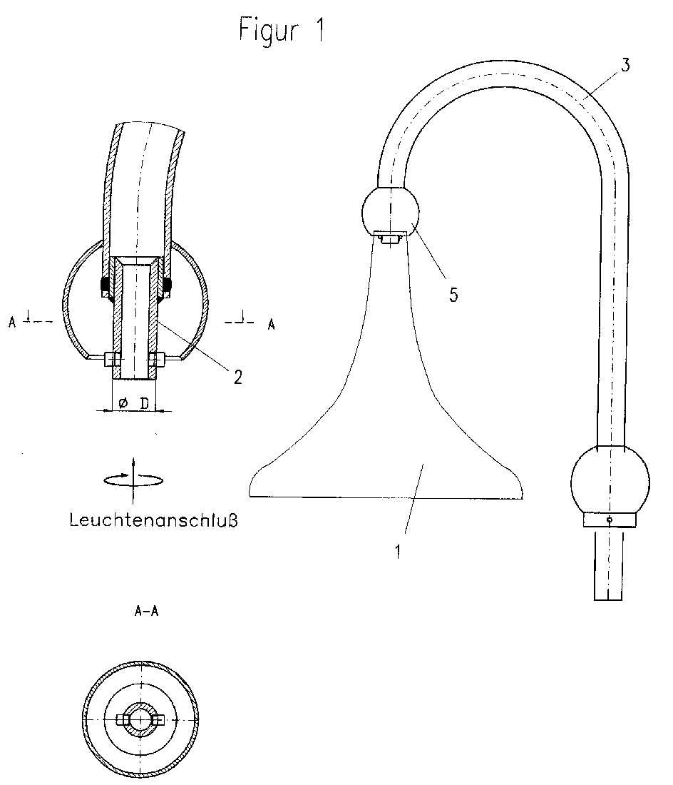
- FIG 1 the outdoor light 1 already attached to the mast bracket 3 is shown.
- the connector located between the mast bracket 3 and the outdoor lamp 1 2 is covered by the cap 5.
- the connecting piece 2 which protrudes into the wall of the mast boom 3 and is attached to the mast boom 3, preferably by a welded connection.
- Figures 2 and 3 show the tubular design according to the invention Connector 2 with two opposite at the bottom on the outside arranged short, cylindrical pins 2.1.
- the pins are 2.1 Part of a quick release for connecting the outdoor light 1 on Connector 2.
- the sleeve 4 shown in Figures 4 and 5 is also part of the Quick release. It is attached to the outdoor lamp 1.
- the top of the in Figure 5 shown sleeve 4 faces the connector 2.
- To the Connecting and releasing the quick fastener are in the sleeve 4 in the longitudinal direction two opposite grooves 4.1 arranged, each of which is from the top Extend the sleeve edge to about the middle of the sleeve 4 and there in one Go over the transverse groove 4.2, which runs slightly towards the upper edge of the sleeve.
- the width of the transverse grooves 4.2 is as large as the width of the grooves 4.1 and slightly larger than the diameter of the arranged on the connector 2 Pins 2.1.
- the wall thickness of the sleeve 4 is less than the length of the Pins 2.1, so that the connector 2 with the pins 2.1 in the sleeve 4 with the grooves 4.1 longitudinally to the end of the grooves 4.1 and at the end of the Grooves 4.1 following the course of the transverse grooves 4.2 can be rotated to the end thereof is.
- a set screw 4.3 is used to prevent rotation.
- the tubular connecting piece 2 is provided with an external thread arranged on the lower edge and the two cylindrical pins 2.1 are arranged opposite one another on the upper edge on the outside.
- the thread is used to connect the exterior light 1 and the pins 2.1 are part of a quick-release fastener for connecting the connecting piece 2 to the mast bracket 3.
- the sleeve 4 shown in FIGS. 4 and 5 is fastened in this case within the mast bracket wall, not shown here.
- the lower edge of the sleeve 4 faces the exterior light 1.
- the grooves 4.1 arranged in the sleeve 4 start from the lower sleeve edge.
- Figures 6 and 7 The already inserted into the sleeve 4 fixed within the mast boom 3 twisted connector 2 is shown in Figures 6 and 7. For simplification the exterior light 1 is not shown in these figures.
- the cut 6 took place alongside the grooves 4.1 through the transverse grooves 4.2 and pins 2.1.
- Figures 6 and 7 thus represent the quick release in the end position, which is after inserting and rotating the Connecting piece 2 sets in the sleeve 4, the pins 2.1 first in the longitudinally arranged grooves 4.1 and then in the transverse grooves 4.2 rotated and - while following the course of the transverse grooves 4.2 - slightly lowered have been.
Landscapes
- Engineering & Computer Science (AREA)
- General Engineering & Computer Science (AREA)
- Lighting Device Outwards From Vehicle And Optical Signal (AREA)
- Arrangement Of Elements, Cooling, Sealing, Or The Like Of Lighting Devices (AREA)
- Non-Portable Lighting Devices Or Systems Thereof (AREA)
- Mutual Connection Of Rods And Tubes (AREA)
Abstract
Description
- Figur 1
- eine Seitenansicht einer an einem Mastausleger befestigten Außenleuchte,
- Figur 2
- einen Längsschnitt durch ein erfindungsgemäßes Verbindungsstück,
- Figur 3
- einen Querschnitt durch ein erfindungsgemäßes Verbindungsstück,
- Figur 4
- einen Querschnitt durch die erfindungsgemäße Hülse,
- Figur 5
- eine Seitenansicht dazu,
- Figur 6
- einen Längsschnitt durch einen Mastausleger mit erfindungsgemäßem
Verbindungsstück und erfindungsgemäßer Hülse
und - Figur 7
- einen Querschnitt durch Mastausleger mit Verbindungsstück und Hülse.
Die in der Hülse 4 angeordneten Nuten 4.1 gehen vom unteren Hülsenrand aus.
- 1
- Außenleuchte
1.1 Innengewinde - 2
- Verbindungsstück
2.1 Stifte
2.2 Gewinde - 3
- Mastausleger
- 4
- Hülse
4.1 Nuten
4.2 Ausnehmungen
4.3 Gewindestift - 5
- Abdeckkappe
Claims (7)
- Vorrichtung zur Befestigung von Außenleuchten (1) an Masten, vorzugsweise an Masten mit bogenförmigen Mastauslegern (3), in dem ein Elektrokabel geführt wird, dadurch gekennzeichnet, dass zwischen dem Mastausleger (3) und der Außenleuchte (1) ein rohrförmiges Verbindungsstück (2) an einem Ende zur Befestigung des Mastauslegers (3) und einem Schnellverschluss am anderen Ende zur Befestigung der Außenleuchte (1) angeordnet ist und dass das Elektrokabel innerhalb des rohrförmigen Verbindungsstückes (2) geführt wird.
- Vorrichtung nach Anspruch 1, dadurch gekennzeichnet, dass der Schnellverschluss als formschlüssige Verbindung zwischen Außenleuchte (1) und Verbindungsstück (2) ausgebildet ist.
- Vorrichtung nach Anspruch 1, dadurch gekennzeichnet, dass der Schnellverschluss als formschlüssige Verbindung zwischen Mastausleger (3) und Verbindungsstück (2) ausgebildet ist.
- Vorrichtung nach Anspruch 2, dadurch gekennzeichnet, dass am Oberteil der Außenleuchte (1) eine zylindrische Hülse (4) befestigt ist, wobei der Außendurchmesser des Verbindungsstückes (2) geringfügig kleiner als der Innendurchmesser der Hülse (4) ist, dass in Längsrichtung innerhalb dieser Hülse (4) von deren dem Mastausleger (3) zugewandtem Rand bis etwa zur halben Hülsenhöhe Nuten (4.1) angeordnet sind, dass innerhalb der Hülse (4) jeweils am der Außenleuchte zugewandten Ende der längs angeordneten Nuten (4.1) ausgehend seitlich neben jeder Nut (4.1) jeweils eine Quernut (4.2) angeordnet ist, die ausgehend von der Nut (4.1) leicht geneigt in Richtung zum dem Mastausleger (3) zugewandten Hülsenrand verläuft, wobei die Breite der Quernuten (4.2) mindestens so groß wie die Breite der Nuten (4.1) ist, dass am der Außenleuchte (1) zugewandten Ende des Verbindungsstückes (2) an dessen Außenseite Stifte (2.1) angeordnet sind, deren Länge geringer als die Wandungsdicke der Hülse (4) und deren Durchmesser geringer als die Breite der Nuten (4.1) sind und dass das Verbindungsstück (2) mit den Stiften (2.1) in die Hülse (4) mit den Nuten (4.1) längs bis zum Ende der Nuten (4.1) einführbar und am Ende der Nuten (4.1) dem Verlauf der Quernuten (4.2) folgend bis zu deren Ende verdrehbar ist.
- Vorrichtung nach Anspruch 3, dadurch gekennzeichnet, dass am Ende des Mastauslegers (3) innerhalb der Wandung des Mastauslegers (3) eine zylindrische Hülse (4) befestigt ist, dass der Außendurchmesser des Verbindungsstückes (2) geringfügig kleiner als der Innendurchmesser der Hülse (4) ist, dass in Längsrichtung innerhalb dieser Hülse (4) von deren der Außenleuchte (1) zugewandtem Rand bis etwa zur halben Hülsenhöhe Nuten (4.1) angeordnet sind, dass innerhalb der Hülse (4) jeweils am der Außenleuchte abgewandten Ende der längs angeordneten Nuten (4.1) ausgehend seitlich neben jeder Nut (4.1) jeweils eine Quernut (4.2) angeordnet ist, die ausgehend von der Nut (4.1) leicht in Richtung zum der Außenleuchte (1) zugewandten Hülsenrand verläuft, dass die Breite der Quernuten (4.2) mindestens so groß wie die Breite der Nuten (4.1) ist, dass am dem Mastausleger (3) zugewandten Ende des Verbindungsstückes (2) an dessen Außenseite Stifte (2.1) angeordnet sind, deren Länge geringer als die Wandungsdicke der Hülse (4) und deren Durchmesser geringer als die Breite der Nuten (4.1) sind und dass das Verbindungsstück (2) mit den Stiften (2.1) in die Hülse (4) mit den Nuten (4.1) längs bis zum Ende der Nuten (4.1) einführbar und am Ende der Nuten (4.1) dem Verlauf der Quernuten (4.2) folgend bis zu deren Ende verdrehbar ist.
- Vorrichtung nach einem der vorhergehenden Ansprüche, dadurch gekennzeichnet, dass oberhalb der Außenleuchte (1) eine das Verbindungsstück (2) einhüllende Abdeckkappe (5) wasserdicht am Ende des Mastauslegers (3) angeordnet ist.
- Vorrichtung nach einem der vorhergehenden Ansprüche, dadurch gekennzeichnet, dass das Verbindungsstück (2) und die Hülse (4) aus Metall bestehen.
Applications Claiming Priority (2)
| Application Number | Priority Date | Filing Date | Title |
|---|---|---|---|
| DE10014471 | 2000-03-23 | ||
| DE10014471A DE10014471A1 (de) | 2000-03-23 | 2000-03-23 | Vorrichtung zur Befestigung von Außenleuchten an Masten |
Publications (3)
| Publication Number | Publication Date |
|---|---|
| EP1136753A2 true EP1136753A2 (de) | 2001-09-26 |
| EP1136753A3 EP1136753A3 (de) | 2004-01-28 |
| EP1136753B1 EP1136753B1 (de) | 2008-08-06 |
Family
ID=7636075
Family Applications (1)
| Application Number | Title | Priority Date | Filing Date |
|---|---|---|---|
| EP01106751A Expired - Lifetime EP1136753B1 (de) | 2000-03-23 | 2001-03-17 | Vorrichtung zur Befestigung von Aussenleuchten an Masten |
Country Status (3)
| Country | Link |
|---|---|
| EP (1) | EP1136753B1 (de) |
| AT (1) | ATE403832T1 (de) |
| DE (2) | DE10014471A1 (de) |
Families Citing this family (1)
| Publication number | Priority date | Publication date | Assignee | Title |
|---|---|---|---|---|
| DE102010003010B4 (de) | 2010-03-18 | 2017-05-04 | manroland sheetfed GmbH | Vorrichtung zum Fördern eines Bogens in einem Bogenausleger einer Bogendruckmaschine |
Citations (2)
| Publication number | Priority date | Publication date | Assignee | Title |
|---|---|---|---|---|
| DE3812668A1 (de) | 1988-04-15 | 1989-10-26 | Siemens Ag | Mastaufsatzleuchte |
| EP0751341A2 (de) | 1995-06-20 | 1997-01-02 | Siemens Aktiengesellschaft | Auslegerarm für eine Aussenleuchte |
Family Cites Families (11)
| Publication number | Priority date | Publication date | Assignee | Title |
|---|---|---|---|---|
| FR1098111A (fr) * | 1954-01-06 | 1955-07-18 | Perfectionnements apportés aux lampes, notamment aux lampes de chevet | |
| CH377934A (de) * | 1959-03-09 | 1964-05-31 | Licentia Gmbh | Gehäuse für eine Mastansatzleuchte |
| DE1800266A1 (de) * | 1968-10-01 | 1970-05-14 | Licentia Gmbh | Tragstutzen zur Befestigung von Leuchten |
| DE2635239C2 (de) * | 1976-08-05 | 1978-05-18 | Langmatz, Hans, 8100 Garmisch-Partenkirchen | Leuchtenfuß für die Verbindung eines Leuchtenkörpers mit einem Mast |
| DE8109307U1 (de) * | 1981-03-30 | 1981-11-05 | Vulkan Werk für Industrie- und Außenbeleuchtung GmbH, 5000 Köln | Reflektorleuchte |
| US4862332A (en) * | 1987-05-18 | 1989-08-29 | Hardy Samuel F | Light fitting support member |
| DE9015063U1 (de) * | 1990-11-02 | 1991-05-29 | Licentia Patent-Verwaltungs-Gmbh, 6000 Frankfurt | Außenleuchte |
| US5149149A (en) * | 1992-01-16 | 1992-09-22 | Wu Wen C | Pipe connecting device with bayonet and interlocking bushing structure |
| DE9215653U1 (de) * | 1992-11-17 | 1993-02-04 | Briloner Leuchten GmbH, 5790 Brilon | Armatur einer Pfostenleuchte (Pollerleuchte) mit Bewegungsmelder |
| EP0770744A3 (de) * | 1995-09-26 | 1997-07-23 | Metalpres Donati S P A | Pfosten für Aussenlampen oder Laternen |
| DE29913138U1 (de) * | 1999-07-27 | 1999-09-23 | Czaja, Marian, 99326 Stadtilm | Mastbogen für Straßenleuchten |
-
2000
- 2000-03-23 DE DE10014471A patent/DE10014471A1/de not_active Ceased
-
2001
- 2001-03-17 EP EP01106751A patent/EP1136753B1/de not_active Expired - Lifetime
- 2001-03-17 AT AT01106751T patent/ATE403832T1/de not_active IP Right Cessation
- 2001-03-17 DE DE50114183T patent/DE50114183D1/de not_active Expired - Fee Related
Patent Citations (2)
| Publication number | Priority date | Publication date | Assignee | Title |
|---|---|---|---|---|
| DE3812668A1 (de) | 1988-04-15 | 1989-10-26 | Siemens Ag | Mastaufsatzleuchte |
| EP0751341A2 (de) | 1995-06-20 | 1997-01-02 | Siemens Aktiengesellschaft | Auslegerarm für eine Aussenleuchte |
Also Published As
| Publication number | Publication date |
|---|---|
| EP1136753A3 (de) | 2004-01-28 |
| ATE403832T1 (de) | 2008-08-15 |
| EP1136753B1 (de) | 2008-08-06 |
| DE50114183D1 (de) | 2008-09-18 |
| DE10014471A1 (de) | 2001-09-27 |
Similar Documents
| Publication | Publication Date | Title |
|---|---|---|
| DE3237892C2 (de) | ||
| DE3932881A1 (de) | System zur befestigung eines beleuchtungsinstrumentes | |
| DE3426212A1 (de) | Schraubklemme fuer elektrische leitungen | |
| EP3527873A1 (de) | Set zur realisierung eines einbaustrahlers | |
| EP1136753B1 (de) | Vorrichtung zur Befestigung von Aussenleuchten an Masten | |
| EP0532980B1 (de) | Haubenmuffe für die Aufnahme von Kabelspleissen | |
| DE9413861U1 (de) | Ein- oder Aufbauleuchte für Verkaufstheken o.dgl. Ladenausstattungsteile | |
| EP0110286B1 (de) | Bausatz zur Halterung einer Lampe an einem Gartenschirm | |
| DE19736006A1 (de) | Gelenkverbindung für Leuchtensystem | |
| DE19906575C2 (de) | Halterung für Seilzüge | |
| DE19808991B4 (de) | Tragvorrichtung für einen Installationskanal | |
| DE29815368U1 (de) | Niedervolt-Deckeneinbauleuchte | |
| EP0338389B1 (de) | Beleuchtungseinrichtung, bestehend aus Mast, Tragarm und Leuchte, insbesondere zur Verwendung als Strassenleuchte | |
| DE4334067A1 (de) | Niedervoltinstallationssystem | |
| DE4203431C2 (de) | Einklink- und Befestigungsvorrichtung | |
| DE19728990C2 (de) | Kabelhalterung zum Befestigen und Herausführen von Kabeln | |
| DE8805207U1 (de) | Straßenleuchte | |
| EP3193076B1 (de) | Reduzierstück zur leuchtenmontage | |
| DE8506832U1 (de) | Leuchtenaufsatz mit mindestens einem Auslegerarm und daran gehalterter Leuchte und mit einem Verbindungselement zur lösbaren Befestigung an einem Leuchtenmast | |
| EP4417765A1 (de) | Verbindungssystem zur verbindung von geländerteilstücken von geländern | |
| DE2422695C3 (de) | Vorrichtung zum Befestigen einer einen AnschluBstutzen aufweisenden Mastleuchte | |
| DE10112694B4 (de) | Befestigungsklemme für ein Kabel | |
| DE9319737U1 (de) | Leuchte | |
| DE4130906A1 (de) | Haubenmuffe fuer die aufnahme von kabelspleissen | |
| EP3869095A1 (de) | Modulare leuchtenstele |
Legal Events
| Date | Code | Title | Description |
|---|---|---|---|
| PUAI | Public reference made under article 153(3) epc to a published international application that has entered the european phase |
Free format text: ORIGINAL CODE: 0009012 |
|
| AK | Designated contracting states |
Kind code of ref document: A2 Designated state(s): AT BE CH CY DE DK ES FI FR GB GR IE IT LI LU MC NL PT SE TR |
|
| AX | Request for extension of the european patent |
Free format text: AL;LT;LV;MK;RO;SI |
|
| PUAL | Search report despatched |
Free format text: ORIGINAL CODE: 0009013 |
|
| AK | Designated contracting states |
Kind code of ref document: A3 Designated state(s): AT BE CH CY DE DK ES FI FR GB GR IE IT LI LU MC NL PT SE TR |
|
| AX | Request for extension of the european patent |
Extension state: AL LT LV MK RO SI |
|
| 17P | Request for examination filed |
Effective date: 20040727 |
|
| AKX | Designation fees paid |
Designated state(s): AT BE CH CY DE DK ES FI FR GB GR IE IT LI LU MC NL PT SE TR |
|
| 17Q | First examination report despatched |
Effective date: 20050329 |
|
| 17Q | First examination report despatched |
Effective date: 20050329 |
|
| GRAP | Despatch of communication of intention to grant a patent |
Free format text: ORIGINAL CODE: EPIDOSNIGR1 |
|
| RAP1 | Party data changed (applicant data changed or rights of an application transferred) |
Owner name: HANS FRANKE KG |
|
| GRAS | Grant fee paid |
Free format text: ORIGINAL CODE: EPIDOSNIGR3 |
|
| GRAA | (expected) grant |
Free format text: ORIGINAL CODE: 0009210 |
|
| AK | Designated contracting states |
Kind code of ref document: B1 Designated state(s): AT BE CH CY DE DK ES FI FR GB GR IE IT LI LU MC NL PT SE TR |
|
| REG | Reference to a national code |
Ref country code: GB Ref legal event code: FG4D Free format text: NOT ENGLISH |
|
| REG | Reference to a national code |
Ref country code: CH Ref legal event code: EP |
|
| REG | Reference to a national code |
Ref country code: IE Ref legal event code: FG4D Free format text: LANGUAGE OF EP DOCUMENT: GERMAN |
|
| REF | Corresponds to: |
Ref document number: 50114183 Country of ref document: DE Date of ref document: 20080918 Kind code of ref document: P |
|
| PG25 | Lapsed in a contracting state [announced via postgrant information from national office to epo] |
Ref country code: ES Free format text: LAPSE BECAUSE OF FAILURE TO SUBMIT A TRANSLATION OF THE DESCRIPTION OR TO PAY THE FEE WITHIN THE PRESCRIBED TIME-LIMIT Effective date: 20081117 Ref country code: NL Free format text: LAPSE BECAUSE OF FAILURE TO SUBMIT A TRANSLATION OF THE DESCRIPTION OR TO PAY THE FEE WITHIN THE PRESCRIBED TIME-LIMIT Effective date: 20080806 |
|
| PG25 | Lapsed in a contracting state [announced via postgrant information from national office to epo] |
Ref country code: FI Free format text: LAPSE BECAUSE OF FAILURE TO SUBMIT A TRANSLATION OF THE DESCRIPTION OR TO PAY THE FEE WITHIN THE PRESCRIBED TIME-LIMIT Effective date: 20080806 |
|
| REG | Reference to a national code |
Ref country code: IE Ref legal event code: FD4D |
|
| PG25 | Lapsed in a contracting state [announced via postgrant information from national office to epo] |
Ref country code: IE Free format text: LAPSE BECAUSE OF FAILURE TO SUBMIT A TRANSLATION OF THE DESCRIPTION OR TO PAY THE FEE WITHIN THE PRESCRIBED TIME-LIMIT Effective date: 20080806 Ref country code: DK Free format text: LAPSE BECAUSE OF FAILURE TO SUBMIT A TRANSLATION OF THE DESCRIPTION OR TO PAY THE FEE WITHIN THE PRESCRIBED TIME-LIMIT Effective date: 20080806 |
|
| PG25 | Lapsed in a contracting state [announced via postgrant information from national office to epo] |
Ref country code: PT Free format text: LAPSE BECAUSE OF FAILURE TO SUBMIT A TRANSLATION OF THE DESCRIPTION OR TO PAY THE FEE WITHIN THE PRESCRIBED TIME-LIMIT Effective date: 20090106 |
|
| PLBE | No opposition filed within time limit |
Free format text: ORIGINAL CODE: 0009261 |
|
| STAA | Information on the status of an ep patent application or granted ep patent |
Free format text: STATUS: NO OPPOSITION FILED WITHIN TIME LIMIT |
|
| 26N | No opposition filed |
Effective date: 20090507 |
|
| PG25 | Lapsed in a contracting state [announced via postgrant information from national office to epo] |
Ref country code: IT Free format text: LAPSE BECAUSE OF FAILURE TO SUBMIT A TRANSLATION OF THE DESCRIPTION OR TO PAY THE FEE WITHIN THE PRESCRIBED TIME-LIMIT Effective date: 20080806 |
|
| BERE | Be: lapsed |
Owner name: HANS FRANKE K.G. Effective date: 20090331 |
|
| PG25 | Lapsed in a contracting state [announced via postgrant information from national office to epo] |
Ref country code: MC Free format text: LAPSE BECAUSE OF NON-PAYMENT OF DUE FEES Effective date: 20090331 |
|
| REG | Reference to a national code |
Ref country code: CH Ref legal event code: PL |
|
| GBPC | Gb: european patent ceased through non-payment of renewal fee |
Effective date: 20090317 |
|
| PGFP | Annual fee paid to national office [announced via postgrant information from national office to epo] |
Ref country code: DE Payment date: 20090903 Year of fee payment: 9 |
|
| REG | Reference to a national code |
Ref country code: FR Ref legal event code: ST Effective date: 20091130 |
|
| PG25 | Lapsed in a contracting state [announced via postgrant information from national office to epo] |
Ref country code: SE Free format text: LAPSE BECAUSE OF FAILURE TO SUBMIT A TRANSLATION OF THE DESCRIPTION OR TO PAY THE FEE WITHIN THE PRESCRIBED TIME-LIMIT Effective date: 20081106 Ref country code: LI Free format text: LAPSE BECAUSE OF NON-PAYMENT OF DUE FEES Effective date: 20090331 Ref country code: CH Free format text: LAPSE BECAUSE OF NON-PAYMENT OF DUE FEES Effective date: 20090331 |
|
| PG25 | Lapsed in a contracting state [announced via postgrant information from national office to epo] |
Ref country code: BE Free format text: LAPSE BECAUSE OF NON-PAYMENT OF DUE FEES Effective date: 20090331 |
|
| PG25 | Lapsed in a contracting state [announced via postgrant information from national office to epo] |
Ref country code: GB Free format text: LAPSE BECAUSE OF NON-PAYMENT OF DUE FEES Effective date: 20090317 Ref country code: FR Free format text: LAPSE BECAUSE OF NON-PAYMENT OF DUE FEES Effective date: 20091123 |
|
| PG25 | Lapsed in a contracting state [announced via postgrant information from national office to epo] |
Ref country code: AT Free format text: LAPSE BECAUSE OF NON-PAYMENT OF DUE FEES Effective date: 20090317 |
|
| PG25 | Lapsed in a contracting state [announced via postgrant information from national office to epo] |
Ref country code: GR Free format text: LAPSE BECAUSE OF FAILURE TO SUBMIT A TRANSLATION OF THE DESCRIPTION OR TO PAY THE FEE WITHIN THE PRESCRIBED TIME-LIMIT Effective date: 20081107 |
|
| PG25 | Lapsed in a contracting state [announced via postgrant information from national office to epo] |
Ref country code: DE Free format text: LAPSE BECAUSE OF NON-PAYMENT OF DUE FEES Effective date: 20101001 |
|
| PG25 | Lapsed in a contracting state [announced via postgrant information from national office to epo] |
Ref country code: LU Free format text: LAPSE BECAUSE OF NON-PAYMENT OF DUE FEES Effective date: 20090317 |
|
| PG25 | Lapsed in a contracting state [announced via postgrant information from national office to epo] |
Ref country code: TR Free format text: LAPSE BECAUSE OF FAILURE TO SUBMIT A TRANSLATION OF THE DESCRIPTION OR TO PAY THE FEE WITHIN THE PRESCRIBED TIME-LIMIT Effective date: 20080806 |
|
| PG25 | Lapsed in a contracting state [announced via postgrant information from national office to epo] |
Ref country code: CY Free format text: LAPSE BECAUSE OF FAILURE TO SUBMIT A TRANSLATION OF THE DESCRIPTION OR TO PAY THE FEE WITHIN THE PRESCRIBED TIME-LIMIT Effective date: 20080806 |