EP1134453A2 - Actionneur pour partie réglable d'un véhicule - Google Patents
Actionneur pour partie réglable d'un véhicule Download PDFInfo
- Publication number
- EP1134453A2 EP1134453A2 EP01105762A EP01105762A EP1134453A2 EP 1134453 A2 EP1134453 A2 EP 1134453A2 EP 01105762 A EP01105762 A EP 01105762A EP 01105762 A EP01105762 A EP 01105762A EP 1134453 A2 EP1134453 A2 EP 1134453A2
- Authority
- EP
- European Patent Office
- Prior art keywords
- drive
- wheels
- cables
- pinion
- cable
- Prior art date
- Legal status (The legal status is an assumption and is not a legal conclusion. Google has not performed a legal analysis and makes no representation as to the accuracy of the status listed.)
- Granted
Links
- 230000001419 dependent effect Effects 0.000 claims 1
- 230000005540 biological transmission Effects 0.000 description 2
- 230000001174 ascending effect Effects 0.000 description 1
- 230000000977 initiatory effect Effects 0.000 description 1
- 230000001360 synchronised effect Effects 0.000 description 1
Images


Classifications
-
- F—MECHANICAL ENGINEERING; LIGHTING; HEATING; WEAPONS; BLASTING
- F16—ENGINEERING ELEMENTS AND UNITS; GENERAL MEASURES FOR PRODUCING AND MAINTAINING EFFECTIVE FUNCTIONING OF MACHINES OR INSTALLATIONS; THERMAL INSULATION IN GENERAL
- F16H—GEARING
- F16H19/00—Gearings comprising essentially only toothed gears or friction members and not capable of conveying indefinitely-continuing rotary motion
- F16H19/02—Gearings comprising essentially only toothed gears or friction members and not capable of conveying indefinitely-continuing rotary motion for interconverting rotary or oscillating motion and reciprocating motion
- F16H19/025—Gearings comprising essentially only toothed gears or friction members and not capable of conveying indefinitely-continuing rotary motion for interconverting rotary or oscillating motion and reciprocating motion comprising a friction shaft
-
- B—PERFORMING OPERATIONS; TRANSPORTING
- B60—VEHICLES IN GENERAL
- B60J—WINDOWS, WINDSCREENS, NON-FIXED ROOFS, DOORS, OR SIMILAR DEVICES FOR VEHICLES; REMOVABLE EXTERNAL PROTECTIVE COVERINGS SPECIALLY ADAPTED FOR VEHICLES
- B60J7/00—Non-fixed roofs; Roofs with movable panels, e.g. rotary sunroofs
- B60J7/02—Non-fixed roofs; Roofs with movable panels, e.g. rotary sunroofs of sliding type, e.g. comprising guide shoes
- B60J7/04—Non-fixed roofs; Roofs with movable panels, e.g. rotary sunroofs of sliding type, e.g. comprising guide shoes with rigid plate-like element or elements, e.g. open roofs with harmonica-type folding rigid panels
- B60J7/057—Driving or actuating arrangements e.g. manually operated levers or knobs
- B60J7/0573—Driving or actuating arrangements e.g. manually operated levers or knobs power driven arrangements, e.g. electrical
-
- F—MECHANICAL ENGINEERING; LIGHTING; HEATING; WEAPONS; BLASTING
- F16—ENGINEERING ELEMENTS AND UNITS; GENERAL MEASURES FOR PRODUCING AND MAINTAINING EFFECTIVE FUNCTIONING OF MACHINES OR INSTALLATIONS; THERMAL INSULATION IN GENERAL
- F16H—GEARING
- F16H19/00—Gearings comprising essentially only toothed gears or friction members and not capable of conveying indefinitely-continuing rotary motion
- F16H19/02—Gearings comprising essentially only toothed gears or friction members and not capable of conveying indefinitely-continuing rotary motion for interconverting rotary or oscillating motion and reciprocating motion
- F16H19/06—Gearings comprising essentially only toothed gears or friction members and not capable of conveying indefinitely-continuing rotary motion for interconverting rotary or oscillating motion and reciprocating motion comprising flexible members, e.g. an endless flexible member
-
- Y—GENERAL TAGGING OF NEW TECHNOLOGICAL DEVELOPMENTS; GENERAL TAGGING OF CROSS-SECTIONAL TECHNOLOGIES SPANNING OVER SEVERAL SECTIONS OF THE IPC; TECHNICAL SUBJECTS COVERED BY FORMER USPC CROSS-REFERENCE ART COLLECTIONS [XRACs] AND DIGESTS
- Y10—TECHNICAL SUBJECTS COVERED BY FORMER USPC
- Y10T—TECHNICAL SUBJECTS COVERED BY FORMER US CLASSIFICATION
- Y10T74/00—Machine element or mechanism
- Y10T74/19—Gearing
- Y10T74/19642—Directly cooperating gears
- Y10T74/19647—Parallel axes or shafts
-
- Y—GENERAL TAGGING OF NEW TECHNOLOGICAL DEVELOPMENTS; GENERAL TAGGING OF CROSS-SECTIONAL TECHNOLOGIES SPANNING OVER SEVERAL SECTIONS OF THE IPC; TECHNICAL SUBJECTS COVERED BY FORMER USPC CROSS-REFERENCE ART COLLECTIONS [XRACs] AND DIGESTS
- Y10—TECHNICAL SUBJECTS COVERED BY FORMER USPC
- Y10T—TECHNICAL SUBJECTS COVERED BY FORMER US CLASSIFICATION
- Y10T74/00—Machine element or mechanism
- Y10T74/20—Control lever and linkage systems
- Y10T74/20396—Hand operated
- Y10T74/20468—Sliding rod
Definitions
- the present invention relates to a drive for an adjustable Vehicle part, in particular a cover element of an openable Vehicle roof that has at least one drive cable and one driven Output pinion includes.
- Such drives are widely used, for example, for covers from Sunroofs and the like are used, usually the output pinion is driven by an electric motor via a reduction gear and is designed as a gear, which between two parallel as Inclined cable trained drive cables is arranged and this through drives direct intervention at one point in opposite directions, see e.g. DE 43 13 687 A1.
- tandem drives for adjustable Vehicle roof elements are known, in which two separate output pinions are provided, each with its own electric motor via its own Reduction gears are driven and in direct engagement with two Drive cables are arranged between these to put them in opposite directions by engaging in one place at a time to drive.
- the force is introduced into each of the two drive cables in two consecutive places, however, are closed
- two separate drives are provided, which is very expensive represents.
- the drive unit comprises at least two wheels, each are engaged with the drive cable or the drive cables, and is as Reduction gear designed for the rotation of the output pinion, the wheels are expediently designed as gears and that Drive cables are designed as gradient cables.
- the drive unit comprises a total of two Wheels that are directly engaged with the output pinion, the Output pinion engages in the teeth of the wheels and the output pinion and the Wheels lie essentially in one plane.
- the diameter or the The number of teeth of the two wheels can be slightly different, the Diameter or number of teeth of the output pinion for the purpose of implementation a reduction is preferably smaller than that of the wheels.
- the simple design is advantageous.
- the drive unit is designed such that that the wheels engaged with the cables via a gear from the Driven pinions are driven, which is preferably realized so that the drive unit two wheels engaged with the cables and has two wheels arranged coaxially and non-rotatably connected to it, which are directly engaged with the output pinion.
- this Embodiment is advantageous in that by appropriate design individual gears can be reduced even more than the first Embodiment.
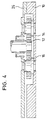
- FIGS 1 to 5 schematically show a first embodiment of a Drive for an adjustable vehicle part, preferably a cover or a another cover element of an openable vehicle roof, e.g. the Cover of a sunroof or sunroof or a slat of one Louvre roofs.
- a frame 10 fixed to the roof there are an output pinion 12, two gears 14 and 16 and two guide tubes 18 and 20 provided, which lead two spiral cables or ascending cables 22 or 24, one end of each in a known manner on the adjustable cover, etc. is attached.
- the roof frame part 10 is also provided with a bearing cover 26 provided, which is omitted in Fig. 1.
- the output pinion 12 in a known manner from a worm wheel of a worm gear 28 driven, the worm wheel with one at the front end of the Shaft of an electric drive motor 30 provided worm shaft Combing so that the rotation of the output pinion 12 with respect to the rotation of the Motor shaft is strongly reduced.
- the axes of rotation or bearing axes of the gears 14 and 16 and the pinion 12 are arranged on a line, the gears 14 and 16 and the Output pinion 12 between the two guide tubes 18 and 20 and thus the drive cables 22 and 24 are arranged.
- the guide tubes 18 and 20 are provided with recesses 32 through which the gears 14 and 16th are each in engagement with the guide cables 22 and 24, each individual of the gears 14 and 16 each in exactly one place with each of the Cable 22 or 24 is engaged.
- the output pinion 12 is in the same Gear level as the gears 14 and 16 arranged and stands with two gears 14 and 16 in meshing engagement, so that a rotation of the Output pinion 12 in one direction an opposite, synchronous Rotation of the gears 14 and 16 causes, which in turn by the Output pinion 12 transmitted torque as driving force in the Initiate drive cable 22 or 24, which in the opposite direction are driven, the introduction of force into each of the two drive cables at two points, namely the point of engagement of the gear 14 and the Point of engagement of the gear 16 takes place.
- the output pinion 12 is not in engagement with the drive cables 22 or 24.
- the diameter or number of teeth of the output pinion 12 is smaller than with the gears 14 and 16, so that compared to a direct Reduction of force from the output pinion into the drive cable he follows.
- the number of teeth of the gears 14 and 16 can be slightly different can be selected, which then results in a not exactly parallel position of the Guide tubes 18 and 20 or the drive cable 22 and 24 results.
- the following number of teeth for gear 14, pinion 12 and the gear 16 can be selected: 22/16/25 and 23/15/26. Is theoretical an equal number of teeth is also possible.
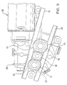
- FIGS. 6 to 8 differs from the previously described embodiment with direct intervention in essentially in that the two gears 115 and 117, which are in engagement with the drive cables 22 and 24, not directly, i.e. in the same Gear plane, are driven by the output pinion 12, but that for this purpose an additional gear wheel (primary wheel) 114 or 116 is provided, each with the output pinion 12 in direct engagement stands and coaxial and rotationally fixed with respect to the gear (secondary wheel) 115 or 117 is arranged to drive it.
- a common shaft 140 is provided on which the gears 114 and 115 or 116 and 117 are rotatably attached.
- Another major advantage of this Embodiment consists in that the teeth of the secondary wheels 115, 117, which are engaged with the drive cables 22 and 24, and the Primary wheels 114, 116, which are in engagement with the output pinion 12, can be chosen differently and therefore with respect to the respective Intervention purpose can be optimized. In particular, there is also a Involute toothing possible.
- a disadvantage of this embodiment compared to the first described embodiment is the larger one Space requirement in the height direction and in the use of additional Components (two additional gears).
- the present invention offers the essential advantage that for Transfer of a predetermined torque of the output pinion to the Drive cable by providing at least two force introduction points for each cable, the stress at the points of application of the force to the prior art, in which only one force introduction point per cable is provided is significantly reduced, which on the one hand the reliability of the drive increased and on the other hand the use for roof systems possible makes, at which very high driving forces have to be transmitted, how e.g. in large roof systems for convertibles, for example.
Landscapes
- Engineering & Computer Science (AREA)
- General Engineering & Computer Science (AREA)
- Mechanical Engineering (AREA)
- Gear Transmission (AREA)
- Devices For Conveying Motion By Means Of Endless Flexible Members (AREA)
- Motor Power Transmission Devices (AREA)
Applications Claiming Priority (2)
| Application Number | Priority Date | Filing Date | Title |
|---|---|---|---|
| DE10012723 | 2000-03-16 | ||
| DE10012723A DE10012723B4 (de) | 2000-03-16 | 2000-03-16 | Antrieb für ein verstellbares Fahrzeugteil |
Publications (3)
| Publication Number | Publication Date |
|---|---|
| EP1134453A2 true EP1134453A2 (fr) | 2001-09-19 |
| EP1134453A3 EP1134453A3 (fr) | 2005-02-09 |
| EP1134453B1 EP1134453B1 (fr) | 2009-10-07 |
Family
ID=7634883
Family Applications (1)
| Application Number | Title | Priority Date | Filing Date |
|---|---|---|---|
| EP01105762A Expired - Lifetime EP1134453B1 (fr) | 2000-03-16 | 2001-03-08 | Actionneur pour partie réglable d'un véhicule |
Country Status (4)
| Country | Link |
|---|---|
| US (1) | US6595081B2 (fr) |
| EP (1) | EP1134453B1 (fr) |
| JP (1) | JP4727052B2 (fr) |
| DE (2) | DE10012723B4 (fr) |
Cited By (1)
| Publication number | Priority date | Publication date | Assignee | Title |
|---|---|---|---|---|
| DE102018116786A1 (de) * | 2018-07-11 | 2020-01-16 | Bombardier Transportation Gmbh | Traktionsvorrichtung mit integriertem Lüfter |
Families Citing this family (8)
| Publication number | Priority date | Publication date | Assignee | Title |
|---|---|---|---|---|
| DE20304478U1 (de) * | 2003-03-20 | 2003-06-12 | Edscha Cabrio Dachsys Gmbh | Vorrichtung zum Antrieb eines Steigungskabels |
| US6796871B1 (en) * | 2003-10-09 | 2004-09-28 | I-Ping Hsieh | Swingable toy |
| US20050109141A1 (en) * | 2003-11-25 | 2005-05-26 | Devore James H. | Automated mechanical transmission system |
| EP1588882B1 (fr) * | 2004-04-19 | 2008-01-23 | Inalfa Roof Systems Group B.V. | Unité d'entrainement de parties mobiles d'un toit ouvrant de véhicule |
| US20080121059A1 (en) * | 2006-07-17 | 2008-05-29 | Double H Technology Co. | Toothed steel cable transmission mechanism |
| DE102008059285A1 (de) | 2008-11-27 | 2010-06-02 | Magna Car Top Systems Gmbh | Antriebseinheit zum Betätigen eines beweglichen Dachelemnts |
| JP6002422B2 (ja) * | 2012-04-03 | 2016-10-05 | ベバスト ジャパン株式会社 | 駆動装置 |
| KR102250260B1 (ko) * | 2014-07-17 | 2021-05-10 | 삼성전자주식회사 | 연결 모듈 및 이를 포함하는 운동 보조 장치 |
Citations (2)
| Publication number | Priority date | Publication date | Assignee | Title |
|---|---|---|---|---|
| DE4313687A1 (de) | 1993-04-27 | 1994-11-03 | Webasto Karosseriesysteme | Fahrzeugdach |
| DE19734815C1 (de) | 1997-08-12 | 1998-06-25 | Webasto Karosseriesysteme | Antriebsvorrichtung für ein verstellbares Fahrzeugteil |
Family Cites Families (16)
| Publication number | Priority date | Publication date | Assignee | Title |
|---|---|---|---|---|
| US3874722A (en) * | 1973-03-20 | 1975-04-01 | Ferro Mfg Corp | Sun roof gear box |
| DE7801538U1 (de) * | 1978-01-20 | 1978-05-03 | Webasto-Werk W. Baier Gmbh & Co, 8031 Stockdorf | Fahrzeugdach |
| US4186524A (en) * | 1978-04-14 | 1980-02-05 | General Motors Corporation | Power actuator for pivotable window |
| DE2848541C2 (de) * | 1978-11-09 | 1980-11-13 | Kombi-Lift Montage- Und Handelsgesellschaft Mbh, 5650 Solingen | Hydraulische Vorrichtung zum Betrieb eines Aufzuges |
| JPS5639350A (en) * | 1979-09-05 | 1981-04-15 | Tsutomu Hasegawa | Telescopic device of tube-form body or the like |
| DE3224896A1 (de) * | 1982-07-03 | 1984-01-05 | Webasto-Werk W. Baier GmbH & Co, 8035 Gauting | Antriebsvorrichtung fuer kraftfahrzeugdaecher |
| US4744172A (en) * | 1985-11-22 | 1988-05-17 | Koito Seisakusho Co., Ltd. | Apparatus for reciprocally moving window panel |
| JPS62125183A (ja) * | 1985-11-22 | 1987-06-06 | 株式会社小糸製作所 | 昇降装置 |
| JPS6397784A (ja) * | 1986-10-13 | 1988-04-28 | 株式会社小糸製作所 | 昇降装置 |
| JPS62203723A (ja) * | 1986-03-04 | 1987-09-08 | Inoue Japax Res Inc | ワイヤガイド装置 |
| DE3809949A1 (de) * | 1988-03-24 | 1989-10-05 | Webasto Ag Fahrzeugtechnik | Vorrichtung zum antrieb eines drucksteif gefuehrten antriebskabels |
| US4920698A (en) * | 1988-10-28 | 1990-05-01 | Noran | Powered sliding truck cab window |
| DE4312687A1 (de) * | 1993-04-20 | 1994-10-27 | Heynau Gmbh Hans | Permanente Kupplung zwischen zwei Wellen |
| JP3536327B2 (ja) * | 1993-11-30 | 2004-06-07 | アイシン精機株式会社 | ドライブギヤ |
| DE19531514C2 (de) * | 1995-08-26 | 2003-11-20 | Arvinmeritor Gmbh | Antriebsvorrichtung für Schiebedächer für Kraftfahrzeuge |
| DE19800557A1 (de) * | 1998-01-09 | 1999-07-15 | Bosch Gmbh Robert | Betätigungsvorrichtung zum Verstellen eines Deckels, insbesondere Schiebedach eines Fahrzeugs |
-
2000
- 2000-03-16 DE DE10012723A patent/DE10012723B4/de not_active Expired - Fee Related
-
2001
- 2001-02-27 JP JP2001052989A patent/JP4727052B2/ja not_active Expired - Fee Related
- 2001-03-08 DE DE50115150T patent/DE50115150D1/de not_active Expired - Lifetime
- 2001-03-08 EP EP01105762A patent/EP1134453B1/fr not_active Expired - Lifetime
- 2001-03-16 US US09/809,632 patent/US6595081B2/en not_active Expired - Lifetime
Patent Citations (2)
| Publication number | Priority date | Publication date | Assignee | Title |
|---|---|---|---|---|
| DE4313687A1 (de) | 1993-04-27 | 1994-11-03 | Webasto Karosseriesysteme | Fahrzeugdach |
| DE19734815C1 (de) | 1997-08-12 | 1998-06-25 | Webasto Karosseriesysteme | Antriebsvorrichtung für ein verstellbares Fahrzeugteil |
Cited By (1)
| Publication number | Priority date | Publication date | Assignee | Title |
|---|---|---|---|---|
| DE102018116786A1 (de) * | 2018-07-11 | 2020-01-16 | Bombardier Transportation Gmbh | Traktionsvorrichtung mit integriertem Lüfter |
Also Published As
| Publication number | Publication date |
|---|---|
| DE50115150D1 (de) | 2009-11-19 |
| EP1134453A3 (fr) | 2005-02-09 |
| JP2001301467A (ja) | 2001-10-31 |
| EP1134453B1 (fr) | 2009-10-07 |
| US20010035062A1 (en) | 2001-11-01 |
| DE10012723A1 (de) | 2001-10-11 |
| JP4727052B2 (ja) | 2011-07-20 |
| DE10012723B4 (de) | 2005-03-10 |
| US6595081B2 (en) | 2003-07-22 |
Similar Documents
| Publication | Publication Date | Title |
|---|---|---|
| DE102010027553A1 (de) | Doppelritzel-Lenkgetriebe | |
| DE3224896C2 (fr) | ||
| DE3201952C2 (de) | Verzweigungsgetriebe für Doppelschneckenmaschinen | |
| EP1134453B1 (fr) | Actionneur pour partie réglable d'un véhicule | |
| DE3639750A1 (de) | Vorrichtung zum hin- und herbewegen einer fensterscheibe | |
| DE10254127B4 (de) | Elektromotorischer Möbelantrieb zum Verstellen von Teilen eines Möbels relativ zueinander | |
| DE2412876A1 (de) | Kunststoffstrangpresse | |
| CH650568A5 (de) | Doppelschraegverzahntes, zweistufiges stirnraedergetriebe und schiffsantrieb. | |
| EP3833891B1 (fr) | Engrenage à crémaillère à deux étages | |
| DE112007001237T5 (de) | Vorrichtung zum Betätigen eines Sonnenschutzes | |
| DE3129648C2 (de) | Sicherungsvorrichtung gegen ungewolltes Abrollen eines Rolltores | |
| EP3768994B1 (fr) | Engrenage planétaire pourvu d'un pignon planétaire à une dent ayant une denture évoloïde | |
| EP1097657B1 (fr) | Unité téléscopique d'entraínement | |
| DE2748918C2 (de) | Doppelschneckenextruder mit miteinander kämmenden konischen Extruderschnecken | |
| DE3508767C2 (fr) | ||
| DE19726398C2 (de) | Antriebssystem für Lamellen | |
| DE19835121A1 (de) | Schneckengetriebe für eine elektrische Lenkhilfe | |
| DE202006014484U1 (de) | Verstelleinrichtung für ein Fahrzeugteil | |
| EP1262624A1 (fr) | Méchanisme pour pivoter des lamelles d'une protection solaire | |
| DE3601766C2 (fr) | ||
| DE102018219521A1 (de) | Elektromotorisch angetriebene Starrachse für Fahrzeuge, insbesondere Nutzfahrzeuge, und Verfahren zu deren Betrieb, Computerprogrammprodukt, Steuerungs- und/oder Regelungsvorrichtung und Kraftfahrzeug | |
| DE1654037A1 (de) | Rollo zum Abdecken von gekruemmten Scheiben,insbesondere in Kraftwagen | |
| DE102019117670B4 (de) | BAURAUMOPTIMIERTES DACHSYSTEM ZUM ÖFFNEN UND SCHLIEßEN EINER DACHÖFFNUNG EINES FAHRZEUGES | |
| DE2006439C3 (de) | Zahnstangenlenkeinrichtung für Kraftfahrzeuge | |
| EP0075649B1 (fr) | Transmission à engrenages angulaire |
Legal Events
| Date | Code | Title | Description |
|---|---|---|---|
| PUAI | Public reference made under article 153(3) epc to a published international application that has entered the european phase |
Free format text: ORIGINAL CODE: 0009012 |
|
| AK | Designated contracting states |
Kind code of ref document: A2 Designated state(s): AT BE CH CY DE DK ES FI FR GB GR IE IT LI LU MC NL PT SE TR |
|
| AX | Request for extension of the european patent |
Free format text: AL;LT;LV;MK;RO;SI |
|
| PUAL | Search report despatched |
Free format text: ORIGINAL CODE: 0009013 |
|
| AK | Designated contracting states |
Kind code of ref document: A3 Designated state(s): AT BE CH CY DE DK ES FI FR GB GR IE IT LI LU MC NL PT SE TR |
|
| AX | Request for extension of the european patent |
Extension state: AL LT LV MK RO SI |
|
| RIC1 | Information provided on ipc code assigned before grant |
Ipc: 7F 16H 19/00 A Ipc: 7E 05F 15/14 B Ipc: 7B 60J 7/057 B |
|
| 17P | Request for examination filed |
Effective date: 20050804 |
|
| AKX | Designation fees paid |
Designated state(s): DE FR GB NL |
|
| 17Q | First examination report despatched |
Effective date: 20080912 |
|
| GRAP | Despatch of communication of intention to grant a patent |
Free format text: ORIGINAL CODE: EPIDOSNIGR1 |
|
| GRAS | Grant fee paid |
Free format text: ORIGINAL CODE: EPIDOSNIGR3 |
|
| RAP1 | Party data changed (applicant data changed or rights of an application transferred) |
Owner name: WEBASTO AG |
|
| GRAA | (expected) grant |
Free format text: ORIGINAL CODE: 0009210 |
|
| AK | Designated contracting states |
Kind code of ref document: B1 Designated state(s): DE FR GB NL |
|
| REG | Reference to a national code |
Ref country code: GB Ref legal event code: FG4D Free format text: NOT ENGLISH |
|
| REF | Corresponds to: |
Ref document number: 50115150 Country of ref document: DE Date of ref document: 20091119 Kind code of ref document: P |
|
| NLV1 | Nl: lapsed or annulled due to failure to fulfill the requirements of art. 29p and 29m of the patents act | ||
| PG25 | Lapsed in a contracting state [announced via postgrant information from national office to epo] |
Ref country code: NL Free format text: LAPSE BECAUSE OF FAILURE TO SUBMIT A TRANSLATION OF THE DESCRIPTION OR TO PAY THE FEE WITHIN THE PRESCRIBED TIME-LIMIT Effective date: 20091007 |
|
| PLBE | No opposition filed within time limit |
Free format text: ORIGINAL CODE: 0009261 |
|
| STAA | Information on the status of an ep patent application or granted ep patent |
Free format text: STATUS: NO OPPOSITION FILED WITHIN TIME LIMIT |
|
| 26N | No opposition filed |
Effective date: 20100708 |
|
| GBPC | Gb: european patent ceased through non-payment of renewal fee |
Effective date: 20100308 |
|
| REG | Reference to a national code |
Ref country code: FR Ref legal event code: ST Effective date: 20101130 |
|
| PG25 | Lapsed in a contracting state [announced via postgrant information from national office to epo] |
Ref country code: FR Free format text: LAPSE BECAUSE OF NON-PAYMENT OF DUE FEES Effective date: 20100331 |
|
| PG25 | Lapsed in a contracting state [announced via postgrant information from national office to epo] |
Ref country code: GB Free format text: LAPSE BECAUSE OF NON-PAYMENT OF DUE FEES Effective date: 20100308 |
|
| PGFP | Annual fee paid to national office [announced via postgrant information from national office to epo] |
Ref country code: DE Payment date: 20170327 Year of fee payment: 17 |
|
| REG | Reference to a national code |
Ref country code: DE Ref legal event code: R119 Ref document number: 50115150 Country of ref document: DE |
|
| PG25 | Lapsed in a contracting state [announced via postgrant information from national office to epo] |
Ref country code: DE Free format text: LAPSE BECAUSE OF NON-PAYMENT OF DUE FEES Effective date: 20181002 |