EP1134053A1 - Structure soudee constituee d'un alliage a faible coefficient de dilatation thermique, et materiau de soudage - Google Patents
Structure soudee constituee d'un alliage a faible coefficient de dilatation thermique, et materiau de soudage Download PDFInfo
- Publication number
- EP1134053A1 EP1134053A1 EP99910816A EP99910816A EP1134053A1 EP 1134053 A1 EP1134053 A1 EP 1134053A1 EP 99910816 A EP99910816 A EP 99910816A EP 99910816 A EP99910816 A EP 99910816A EP 1134053 A1 EP1134053 A1 EP 1134053A1
- Authority
- EP
- European Patent Office
- Prior art keywords
- welding
- less
- weld metal
- carbide
- cracking
- Prior art date
- Legal status (The legal status is an assumption and is not a legal conclusion. Google has not performed a legal analysis and makes no representation as to the accuracy of the status listed.)
- Granted
Links
Images


Classifications
-
- C—CHEMISTRY; METALLURGY
- C22—METALLURGY; FERROUS OR NON-FERROUS ALLOYS; TREATMENT OF ALLOYS OR NON-FERROUS METALS
- C22C—ALLOYS
- C22C38/00—Ferrous alloys, e.g. steel alloys
- C22C38/10—Ferrous alloys, e.g. steel alloys containing cobalt
- C22C38/105—Ferrous alloys, e.g. steel alloys containing cobalt containing Co and Ni
-
- B—PERFORMING OPERATIONS; TRANSPORTING
- B23—MACHINE TOOLS; METAL-WORKING NOT OTHERWISE PROVIDED FOR
- B23K—SOLDERING OR UNSOLDERING; WELDING; CLADDING OR PLATING BY SOLDERING OR WELDING; CUTTING BY APPLYING HEAT LOCALLY, e.g. FLAME CUTTING; WORKING BY LASER BEAM
- B23K35/00—Rods, electrodes, materials, or media, for use in soldering, welding, or cutting
- B23K35/22—Rods, electrodes, materials, or media, for use in soldering, welding, or cutting characterised by the composition or nature of the material
- B23K35/24—Selection of soldering or welding materials proper
- B23K35/30—Selection of soldering or welding materials proper with the principal constituent melting at less than 1550 degrees C
- B23K35/3033—Ni as the principal constituent
-
- B—PERFORMING OPERATIONS; TRANSPORTING
- B23—MACHINE TOOLS; METAL-WORKING NOT OTHERWISE PROVIDED FOR
- B23K—SOLDERING OR UNSOLDERING; WELDING; CLADDING OR PLATING BY SOLDERING OR WELDING; CUTTING BY APPLYING HEAT LOCALLY, e.g. FLAME CUTTING; WORKING BY LASER BEAM
- B23K35/00—Rods, electrodes, materials, or media, for use in soldering, welding, or cutting
- B23K35/22—Rods, electrodes, materials, or media, for use in soldering, welding, or cutting characterised by the composition or nature of the material
- B23K35/24—Selection of soldering or welding materials proper
- B23K35/30—Selection of soldering or welding materials proper with the principal constituent melting at less than 1550 degrees C
- B23K35/3053—Fe as the principal constituent
- B23K35/3066—Fe as the principal constituent with Ni as next major constituent
-
- C—CHEMISTRY; METALLURGY
- C22—METALLURGY; FERROUS OR NON-FERROUS ALLOYS; TREATMENT OF ALLOYS OR NON-FERROUS METALS
- C22C—ALLOYS
- C22C38/00—Ferrous alloys, e.g. steel alloys
- C22C38/005—Ferrous alloys, e.g. steel alloys containing rare earths, i.e. Sc, Y, Lanthanides
-
- C—CHEMISTRY; METALLURGY
- C22—METALLURGY; FERROUS OR NON-FERROUS ALLOYS; TREATMENT OF ALLOYS OR NON-FERROUS METALS
- C22C—ALLOYS
- C22C38/00—Ferrous alloys, e.g. steel alloys
- C22C38/08—Ferrous alloys, e.g. steel alloys containing nickel
-
- C—CHEMISTRY; METALLURGY
- C22—METALLURGY; FERROUS OR NON-FERROUS ALLOYS; TREATMENT OF ALLOYS OR NON-FERROUS METALS
- C22C—ALLOYS
- C22C38/00—Ferrous alloys, e.g. steel alloys
- C22C38/12—Ferrous alloys, e.g. steel alloys containing tungsten, tantalum, molybdenum, vanadium, or niobium
-
- C—CHEMISTRY; METALLURGY
- C22—METALLURGY; FERROUS OR NON-FERROUS ALLOYS; TREATMENT OF ALLOYS OR NON-FERROUS METALS
- C22C—ALLOYS
- C22C38/00—Ferrous alloys, e.g. steel alloys
- C22C38/14—Ferrous alloys, e.g. steel alloys containing titanium or zirconium
-
- Y—GENERAL TAGGING OF NEW TECHNOLOGICAL DEVELOPMENTS; GENERAL TAGGING OF CROSS-SECTIONAL TECHNOLOGIES SPANNING OVER SEVERAL SECTIONS OF THE IPC; TECHNICAL SUBJECTS COVERED BY FORMER USPC CROSS-REFERENCE ART COLLECTIONS [XRACs] AND DIGESTS
- Y10—TECHNICAL SUBJECTS COVERED BY FORMER USPC
- Y10T—TECHNICAL SUBJECTS COVERED BY FORMER US CLASSIFICATION
- Y10T428/00—Stock material or miscellaneous articles
- Y10T428/12—All metal or with adjacent metals
- Y10T428/12493—Composite; i.e., plural, adjacent, spatially distinct metal components [e.g., layers, joint, etc.]
- Y10T428/12771—Transition metal-base component
- Y10T428/12861—Group VIII or IB metal-base component
- Y10T428/12951—Fe-base component
- Y10T428/12958—Next to Fe-base component
- Y10T428/12965—Both containing 0.01-1.7% carbon [i.e., steel]
Definitions
- the present invention relates to an article serving as storage tanks, pipelines, and various equipments associated with them for cryogenic substances, such as liquefied natural gas (LNG), in which all or part of members of the article are formed of a Fe-Ni low thermal expansion coefficient alloy and are assembled by welding.
- LNG liquefied natural gas
- the present invention also relates to a welded pipe used in the above pipelines. Furthermore, the present invention relates to a welding material (wire) suitable for use in manufacturing the welded structure and the welded pipe as described above.
- austenitic stainless steels such as JIS - SUS 304
- cryogenic substances such as the liquefied natural gas (LNG).
- LNG liquefied natural gas
- the austenitic stainless steel has a high thermal expansion coefficient.
- the pipeline can be formed of a material having a remarkably low thermal expansion coefficient which allows the loop pipe to be eliminated, an elbow pipe involved in the loop pipe will become unnecessary and thereby the diameter of a tunnel for letting the pipeline pass through will be able to be reduced. This will allow maintenance operations for thermal insulations of the pipeline or the like to be minimized, and will open the way to significantly economize construction costs and operation-maintenance expenses.
- a Fe-Ni alloy of a particular component ratio has an extremely low linear expansion coefficient.
- Typical examples of such an alloy are Fe-36 % Ni alloy and Fe-42 % Ni alloy, which are collectively referred to as Invar alloy ("%" concerning each content of components means “weight %” herein). These alloys are used as a material for equipment in which the expansion, and/or contraction due to temperature variation, is undesirable.
- the welding material disclosed in the above Japanese Patent Laid-Open Publication No. 4-231194 includes C: 0.05 to 0.5 % and Nb: 0.5 to 5 % as well as Ni (Co) and Fe, and, as needed, selectively includes Mn, Ti, Al, Ce, Mg el al., whereby cracking in welding operations can be prevented.
- the welding material disclosed in the Japanese Patent Laid-Open Publication No. 7-267272 includes Ni: 30 to 45 %, C: 0.03 to 0.3 %, Nb: 0.1 to 3 %, P: 0.015 % or less, S: 0.005 % or less, Si: 0.05 to 0.6 %, Mn: 0.05 to 4 %, AI: 0.05 % or less, and O (oxygen): 0.015 % or less, wherein the relationship between Nb and C is defined by (% Nb) x (% C) ⁇ 0.01, whereby the reheat cracking in the multi-layer welding operation is prevented and the toughness of the welded zone is also improved.
- the welding material is required to have an excellent weldability in fabrication.
- weld defects such as incomplete formation of root pass bead or lack of fusion cased by insufficient weld penetration or missing of a weld line straightness, and not to allow burn though or lack of penetration in root pass to arise even during the welding in an overhead position.
- solidification cracking means a cracking which arises in a weld metal (bead) during solidification.
- reheat cracking means a cracking which arises in an initially formed weld metal (bead), which originally had no cracking, by a thermal affection at the time when the initially formed weld metal is reheated by an additional weld metal superposed thereon.
- the weld metal is required to have an adequate stress corrosion cracking resistance, as well as toughness under a low temperature, as described above.
- a an insulating material such as urethane resin, which includes a small amount of CI - , and these structures are often situated close to an ocean and exposed to the atmosphere containing CI - due to sea water.
- the above invention disclosed in the Japanese Patent Laid-Open Publication No. 7-267272 has an objective to improve the cold toughness of welded zone. However, it does not discuss any measure for the stress corrosion cracking resistance.
- the welding material used for fabricating the above welded structure is required to be readily produced, or to be readily converted into a wire (i.e. required to have good workability), and is also required to facilitate welding operations when such a material is applied (i.e. required to have good welding weldability in fabrication).
- welding materials i.e., welding wires
- a hot working of raw materials and a cold working for wire drawing are essential.
- the welding materials proposed until the present time have an inferior workability, resulting in a complexified process for converting into wires and also an increased manufacturing cost.
- an automatic welding based on the TIG or plasma welding process is applied to enhance the efficiency of operations.
- it is required to provide an excellent weldability in fabrication, such as a capability of welding in various positions, because such assembling operations are often carried out on site.
- weld defects such as the incomplete formation of root pass bead, or lack of fusion caused by insufficient weld penetration, or missing of a weld line in the automatic welding operation, and not to allow the burn through or incomplete formation of root bead to arise during the welding operation in the overhead position.
- weld defects such as the incomplete formation of root pass bead, or lack of fusion caused by insufficient weld penetration, or missing of a weld line in the automatic welding operation, and not to allow the burn through or incomplete formation of root bead to arise during the welding operation in the overhead position.
- such requirements have not been considered in the welding materials proposed until this time.
- the welded structure of the present invention has members joined to each other by welding, and at least one of the members is formed of a Fe-Ni-base low thermal expansion coefficient alloy.
- the welded structure is characterized by the following (A) and (B);
- the welded pipe of the present invention is produced by shaping a plate of Fe-Ni-base low thermal expansion coefficient alloy in tubular shape and then welding its abutting portions.
- This pipe is used primarily in a pipeline for low temperature cryogenic substances.
- the pipeline is assembled by circumferential butt welding_of plural pipes.
- the term "welded pipe” also includes a pipe joint, such as a branch tube or an elbow, applied in a particular portion of the pipeline, as long as such a pipe joint is produced by welding.
- the welded pipe of the present invention also has said features (A) and (B).
- a carbide existing in columnar crystal grain boundaries is 0.5 to 50 volume % of the weld metal, wherein Nb and/or Zr in said carbide is 20 weight % or more % of said carbide.
- the welding material of the present invention is suitable to be used for forming a weld metal of Fe-Ni low thermal expansion coefficient alloy, and is characterized by the following features (C) and (D);
- the solidification cracking could be explained as a phenomenon in which the weld metal had a portion where a liquid phase of the concentrated Si and C resided for a long time and then the weld metal was cracked at said portion under a certain external force. It was also believed that the reheat cracking was caused by two factors; Si and C forms a eutectic compound having a low melting point in conjunction with Fe in the matrix, and the resulting compound is heated and molten by subsequent welding passes to cause the cracking; and a fixing force of grain boundaries in the bead is weakened due to the segregation of S at the grain boundaries and this portion is cracked by a thermal stress from subsequent passes.
- the crystallization of carbide at high temperature also contributes effectively to the creation of the complexified configuration of the columnar crystal grain boundaries during the solidification and to disperse the thermal stress yielded therein so as to reduce stress concentration. Accordingly the cracking can be prevented even if some liquid phase exists in the columnar crystal grain boundaries. The solidification cracking is supposedly prevented by this combined action.
- Nb and Zr are the most effective elements to form the above-mentioned carbide. Either one of these elements may be effectively applied, or both of them may otherwise be applied together.
- a suitable content of Nb and/or Zr in the weld metal is required to satisfy the following formulas 1 ⁇ and 2 ⁇ ; Si ⁇ 0.1 (Nb + Zr) + 0.05 % 1 S ⁇ 0.0015 (Nb + Zr) + 0.0055 % 2
- creating the carbide is effective to prevent cracking in welding.
- an excessive amount of the carbide leads to a deteriorated cold toughness.
- the amount of the carbide in the weld metal is required to be defined up to a predetermined limit.
- a surface treatment is also effective to prevent stress corrosion cracking. Applying the surface treatment, such as shot peening, sand blasting et al., allows compressive stress to remain on the surface of the weld metal, so that the stress corrosion cracking resistance can be enhanced.
- a coating may be applied to isolate the weld metal from a corrosive environment.
- the welded metal surface formed by circulating welding may be coated with a suitable organic substance, such as a combination of an epoxy resin cured by an amine and a polyol resin cured by isonate, or one component type epoxy resin cured by ketimine, so as to prevent from stress corrosion cracking.
- the effect of preventing the cracking in the weld metal and improving the stress corrosion cracking resistance of the weld metal can be obtained by providing C in the weld metal as the carbide.
- This utilization of the carbide is the most important means to solve various problems involved in the welding of the Fe-Ni low thermal expansion coefficient alloy.
- This carbide is required to exist in the columnar crystal grain boundaries of the solid weld metal.
- the amount of the carbide is 0.5 volume % or more of the weld metal, however, since its exceeding existence leads to a deterioration of cold toughness, the amount of the carbide should be limited to 50 volume % or less.
- the element needed to form the carbide can be any element, such as Cr, Mo, Ti, Ta, Hf, Nd et al., which forms stable carbide at high temperature.
- at least the carbide of Nb and/or Zr, i.e., (Nb, Zr) C is included.
- the content of Nb and/or Zr in the carbide is preferable to be 20 weight % or more of the carbide because the carbide can be stable and have a higher melting point in this case.
- Nb and/or Zr are effective in order to improve the properties of the weld metal.
- Nb and Zr tend to create large size oxides because these elements have a strong affinity with oxygen. These oxides dissolve S in the weld metal and contribute to the prevention of the reheat cracking. On the other hand, these oxides increase the deformation resistance during the production of the welding material so that workability is significantly deteriorated.
- Nb and/or Zr as carbide, i.e. (Nb, Zr) C
- the required amount of C in the welding material for creating said carbide increases according to the increase of the amount of Nb and/or Zr.
- the contents of C and Nb and/or Zr are required to satisfy the following formula 3 ⁇ ; C ⁇ 0.015 (Nb + Zr) + 0.04 % 3
- the welded structure of the present invention is characterized in that its weld metal has the aforementioned chemical composition and satisfies the aforementioned formulas 1 ⁇ and 2 ⁇ .
- the reasons for defining the respective contents of alloy components are described as follows. Ni: 30 to 45 %
- Ni is the primary element which forms a low thermal expansion coefficient alloy. In order to obtain a sufficiently low linear expansion coefficient in the weld metal, Ni is required to be 30 to 45 %. A preferable lower limit is 32 %, and a more preferable lower limit is 34 %. A preferable upper limit is 43 %. Co: 0 to 10%
- Co may be added as needed because Co is an element acting to the lower thermal expansion coefficient and stabilize the austenite as with Ni.
- more than 10 % of the content of Co leads to a deteriorated toughness of the weld metal and to a necessity of using a higher price welding material to obtain such a weld metal.
- its content should be limited to 10 % or less, preferably to 8 % or less, and more preferably to 6 % or less.
- C 0.03 to 0.5 %
- C is an element stabilizing the austenite matrix.
- C reacts with the segregated Si in grain boundaries and Fe in the matrix so as to create the low melting point compound, and thereby to provide an increased cracking sensitivity.
- its content should be limited to 0.5 % or less, more preferably to 0.4% or less.
- C also acts to create the carbide in the weld metal so as to complexify the columnar crystal grain boundaries, and thereby to provide an improved stress corrosion cracking resistance of the weld metal.
- C is required to be contained 0.03 % or more.
- Si is added as a deoxidizing agent.
- Si segregates in the grain boundaries during the solidification of the weld metal, then reacts with C and Fe in the matrix to create the low melting point compound, and consequently causes reheat cracking in multi-layer welding.
- Nb and Zr reduce the reheat cracking sensitivity by fixing C
- the content of Si should be limited to 0.1 (Nb + Zr) + 0.05 % or less to assure a sufficient resistance to reheat cracking.
- the lower limit may be set at about 0.005 % because excessive reduction of Si leads to an increased manufacturing cost.
- Mn 0.7% or less
- Mn is added as a deoxidizing element during the alloy making as with Si.
- its content is set in 0.7 % or less, and preferably in 0.6 % or less in order to obtain a more excellent impact characteristic. While its lower limit has no particular restriction, the practical lower limit is about 0.005 % because excessive Mn reduction increases manufacturing cost as with Si.
- Nb and Zr act to form carbide in combination with C in the weld metal, and thereby prevent the solidification cracking and reheat cracking of the weld metal and also provide an improved toughness and stress corrosion cracking resistance.
- either one of or the total of Nb and Zr is required to be included at 0.05 % or more.
- more than 4 % of Nb and/or Zr causes an increased free Nb and/or Zr in the grain boundaries and a lowered strength of the grain boundaries.
- oxide of Nb and Zr is formed and this leads to a deteriorated toughness of the weld metal.
- P is an inevitable impurity and is required to be 0.02 % or less because P increases the solidification cracking sensitivity in welding operations. It is preferable to be 0.015 % or less, more preferably 0.010 % or less. While excessive reduction of P leads to an increased manufacturing cost, its reduction is enforceable to the extent of 0.0005 %. S: 0.0015 (% Nb + % Zr) + 0.0055 % or less (the range of the aforementioned formula 2 ⁇ )
- S is an inevitable impurity, which forms a compound having a low melting point during the solidification in the welding operations and thereby arises the solidification cracking.
- S segregates in the grain boundaries to lower the fixing force of the grain boundaries and thereby increases the reheat cracking sensitivity in multi-layer welding.
- the grain boundary having the segregated S serves as a starting point of stress corrosion cracking, particularly in the environment containing Cl - ion.
- Nb and/or Zr is a suitable element to form this carbide, and the respective contents of these elements and S should be controlled by the formula 2 ⁇ .
- AI is a strong deoxidizing element. However, an excessive addition increases the amount of inclusion and lowers the toughness of the weld metal.
- the content of AI is set at 0.01 % or less, preferably at 0.008 % or less. While the content of AI may be substantially zero, the lower limit should be about 0.0002 % in view of the effect as deoxidizing agent and the manufacturing cost.
- Rare earth element 0 to 0.5 %
- Rare earth element represented by Y and La, acts to fix S and may be added as needed because of its effect to prevent reheat cracking. However, its content should be limited to 0.5 % or less, preferably to 0.4 % or less because its excessive addition leads to a deteriorated cleanliness and a lowered workability and toughness of the weld metal. When the rare earth element is added in expectation of the above effect, 0.001 % or more may be desirably selected.
- the remainder of the weld metal can substantially be Fe, or one or more auxiliary components, which are included in the base material of a Fe-Ni low thermal expansion coefficient alloy, such as Ti, Ta, Cr, Mo, Hf, Nd et al., can be additionally included in about 0.5 % or less respectively. These components create the carbide in the weld metal and thereby contribute to the prevention of cracking and the improvement of stress corrosion cracking resistance.
- both members to be joined to each other by welding may be made of a Fe-Ni low thermal expansion coefficient alloy, or either one of the members may be made of a different alloy such as stainless steel.
- a stainless steel component such as joints, valves, or the like, is occasionally installed in the pipeline.
- so-called dissimilar metal welding wherein the component is welded to the pipe made of a Fe-Ni low thermal expansion coefficient alloy, is carried out.
- This welding may be adequately carried out when the weld metal satisfies the aforementioned conditions.
- a dilution ratio is preferably limited to 50 % or less. More than 50 % of dilution ratio leads to an increased content of Cr in the carbide within the weld metal due to the diffusion of Cr from the stainless steel, resulting in a lowered melting point of the carbide which could possibly induce reheat cracking.
- Any existing Fe-Ni low thermal expansion coefficient alloy may be applied as a base material of the structure or welded pipe.
- a Fe-base alloy comprises Ni: 30 to 45 %, Co: 0 to 10 % or less, Mn: 1.0 % or less, Si: 1.0 % or less, C: more than 0.2 % to 0.5 %, Nb: more than 0.5 % to 2.0 %, and rare earth element: 0 to 0.5 %, with impurities being S: 0.01 % or less, P: 0.01 % or less, Al: 0.01 % or less, and O (oxygen): 0.01 % or less, wherein the respective contents of S, O and Nb satisfy the following formula; S + O ⁇ 0.005 x Nb + 0.01 (%) 7
- this alloy includes a relatively large amount of C and also includes Nb, even if welding is carried out with a relatively high dilution ratio, Nb and C is supplied from the base material to the weld metal so that NbC can be assured in the weld metal.
- Nb since the content of Nb is arranged to satisfy the above formula 7 ⁇ , oxygen and S are combined with each other to form Nb (S, O).
- Nb S, O
- this alloy may be sufficiently free from reheat cracking. This alloy is useful particularly as a material for producing the welded pipe.
- the weld metal having the composition defined in the present invention, has practically sufficient characteristics as welded.
- the weld metal may subject to an annealing treatment at 300 to 700°C for relieving residual stress and for reducing stress corrosion cracking sensitivity.
- the heating time may be set in the range of "t /20" hour to "t / 5" hour, where t (mm) is the thickness of the member to be welded (base material).
- t (mm) is the thickness of the member to be welded (base material).
- the heating temperature is lower than 300°C or the heating time is shorter than "t /20" hour, the effect of relieving the residual stress cannot be obtained.
- Heating at temperature of higher than 700°C causes the redistribution of S to arise and thereby reheat cracking and stress corrosion cracking sensitivities are reversely increased. Heating longer than "t / 5" hour leads to a creation of exceeding carbide in grain boundaries and a lowered cold toughness.
- a structure having the aforementioned weld metal of the present invention can be obtained by using a welding material having a particular chemical composition determined in consideration of dilution ratio, depending on welding conditions.
- a welding material having a particular chemical composition determined in consideration of dilution ratio, depending on welding conditions.
- Ni is a primary element forming a low thermal expansion coefficient alloy, and Ni in the welding material moves into the weld metal.
- the reason for the definition of its content is the same as in the aforementioned weld metal.
- Co is a component which may be added as needed. Similar to Ni, Co in the welding material also moves into the weld metal. Thus, the reason for the definition of its content is the same as in the aforementioned weld metal.
- C 0,5 % or less, and (Zr + Nb) + 0.04 % or more (the range of the formula 3 ⁇ )
- C acts to stabilize the austenite in the weld metal, but increases reheat cracking sensitivity.
- C is fixed as a carbide of Nb and/or Zr, as described above, the reheat cracking sensitivity can be lowered and this carbide contributes to the prevention of cracking and also to the improvement of the stress corrosion cracking resistance of the weld metal.
- the welding material is required to include (Zr + Nb) + 0.04 % or more of C.
- exceeding C leads to the aforementioned harmful effect to the weld metal and to a damaged workability (hot and cold workability) of the welding material.
- the upper limit should be 0.5 %.
- the content of Si should be in the range of the above formula 1 ⁇ for the same reason as in the weld metal. Further, Si affects the properties of the weld metal and dominates weldability in fabrication. This affect has relation to the content of Mn. Thus, the welding material is required to satisfy the following formula 4 ⁇ . Mn: 0.7 % or less and in the range of 0.1 ⁇ (Si / Mn) ⁇ 2.0 (the formula 4 ⁇ )
- the reason for determining the upper limit (0.7 %) is the same as in the weld metal.
- "Si/Mn" affects the weldability in fabrication. When this ratio is smaller than 0.1, the composition of slag created on the surface of molten pool becomes Mn-rich and the weld metal tends to be a convex bead, resulting in lack of fusion. On the other hand, when this ratio exceeds 2.0, the viscosity of the weld metal lowers and thereby the drop-down of the weld metal arises during the overhead welding.
- Mn in the welding material is required to satisfy the above formula 4 ⁇ .
- Nb and/or Zr As described above, 0.05 % or more of Nb and/or Zr is required to be included in the weld metal.
- the lower limit in the welding material should be 0.2 % in consideration of the dilution by the base material during welding.
- the upper limit should be 4 % for the same reason as in the weld metal. In view of manufacturing performance, it is also required to satisfy the aforementioned relationship with the content of C (the formula 3 ⁇ ).
- P which is an inevitable impurity in the welding material, moves into the weld metal and increases solidification cracking sensitivity.
- the weld metal it is limited to 0.02 % or less, preferably to 0.015 % or less, and more preferably to 0.010 % or less.
- the content of S is required to satisfy the formula 2 ⁇ in order to prevent the reheat cracking of the weld metal.
- S is an element which strongly affects weldability in fabrication.
- it is required to satisfy the formula 5 ⁇ in relation to the contents of oxygen (O).
- the reason for the upper limit (0.01 %) is the same as in the weld metal. AI tends to form slag in combination with oxygen, and consequently resists the heat input from the arc to the base metal, resulting in lack of penetration in root pass. For preventing this, it is required to satisfy the formula 6 ⁇ . As with the weld metal, the content of Al can be substantially zero.
- the remainder in the components forming the welding material of the present invention, may be substantially Fe. Additionally auxiliary component(s) such as about 0.5 % or less respectively of Ti, Ta, Cr, Mo, Hf, Nd et al., which may be included in the weld metal may also be included.
- Any welding process may be optionally selected to produce the welded structure of the present invention. Even if any welding process is applied, when a formed weld metal has the chemical composition within the aforementioned range and satisfies the formulas 1 ⁇ and 2 ⁇ , no cracking arises and an excellent cold toughness may be achieved.
- the welding material of the present invention is used in TIG or the plasma welding process. Because, in these welding processes, the wastage of alloy elements in the welding material is low and the welded material of low oxygen content can be obtained so that further improved cold toughness may be effectively achieved.
- a fine weld metal may be obtained through all position welding.
- the circulating welding for jointing pipes may also be automated.
- a pipe (welded pipe) may readily be manufactured by welding a formed plate of a Fe-Ni low thermal expansion coefficient alloy through the seam welding process with this material.
- This pipe has a welded zone which has excellent characteristics and can be suitably applied as a pipeline of cryogenic substances, such as LNG et al.
- the TIG welding was carried out in a respective flat position and overhead position. Then, the root pass bead forming capability of a welding bead in the first layer, the uniformity of welding bead, and the flatness of welding bead were evaluated. The plasma welding operation was carried out in downward position. Then, the root pass bead forming capability and the uniformity of welding bead were evaluated. In the evaluation of the root pass bead forming capability, when a root pass bead was formed all over the weld line (root pass bead formation ratio: 100 %), it was evaluated as acceptable.
- the width of the welding bead was measured at even intervals, and the difference between maximum and minimal widths ( ⁇ W) and the average value (W ave ) were determined. Then, when their ratio ( ⁇ W /W ave did not exceed 0.2, it was evaluated as acceptable.
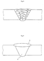
- welded joints were produced by applying the base materials having the joint geometries 1 and 2 shown in Figs. 1 and 2; using the welding materials shown in Table 1; and in the TIG welding process, welding with 6 multi-layer welding layers having B1 to B12 of 12 paths shown in Fig. 4, and in the plasma welding process, welding with one plasma welding layer shown by the reference number 4 in Fig. 5 and one TIG welding layer shown by the reference number 5 in Fig. 5.
- Test specimens for chemical analysis were taken from the weld metals of produced joints to carry out chemical analyses.
- the ratio of the carbide in the columnar crystal grain boundary of the weld metal was also measured by observing microstructure of the weld metal by using an electron microscope, and the composition of the carbide was analyzed by EDX analysis to determine respective contents of Nb and Zr in the carbide.
- test specimen 6 for the bending test shown in Fig. 6 (a) (the reference number 7 indicates the weld metal portion) and a test specimen 8 of the V-notch Charpy impact test (the notch was provided in the weld metal portion) were taken and they were put to a verification test for checking the existence of reheat cracking and an impact test at -196°C.
- the test specimen was applied with a slight curvature as shown in Fig. 6(b). When there was a microscopic reheat cracking, it was opened. Then, the weld metal portion was observed with 100 to 500 magnifications using an optical microscope to check the occurrence of reheat cracking. In criteria of the verification test, no cracking was evaluated as an acceptable one, and when even one cracking arose in the test specimen, it was evaluated as a failure.
- a double U-bent test specimen 9 as shown in Fig. 8 was taken from the welded joint.
- stress corrosion cracking resistance was evaluated by observing a sectional microstructure in the parallel direction to tensile stress, using an optical microscope of 50 magnifications to check the occurrence of cracking.
- the size of the test specimen 9 was 10 mm x 75 mm x 2 mm.
- the test specimen was kept under restraint in the U-shape by a bolt 11 and a nut 12, with setting the weld metal 10 on the center.
- AWJ1 to AWJ20 having the chemical composition of the weld metal in the range defined in the present invention, do not raise any reheat cracking in the weld metal and have a practically sufficient impact characteristic of not lower than 30 J/cm 2 under -196°C of very low temperature.
- AWJ20 is an example in which C2 in Table 3, including Nb is applied as its base material.
- AWJ3 in which C1 including no Nb is applied as its base material, applicable range of the formulas 1 ⁇ and 2 ⁇ are broadened out. This proves that the base material of C1, including Nb, is suitable for the welding having high dilution ratio.
- the welded joints (BWJ1 to BWJ12) having the chemical composition of the weld metal out of the range defined in the present invention raise reheat cracking and their impact values do not measure up to 30 J/cm 2 .
- the reheat cracking resistance, toughness and stress corrosion cracking resistance could not be satisfied together.
- the welded structure of the present invention has a weld metal free from cracking and achieving an excellent low temperature toughness and stress corrosion cracking resistance.
- the welding material of the present invention can be readily manufactured and provides a sufficient weldability in fabrication so that circulating welding or automatic welding in all positions can be carried out by using this welding material.
- the present invention contributes greatly to the production of welded pipes using Fe-Ni low thermal expansion coefficient alloy as a raw material thereof, pipelines formed by jointing such welded pipes, and welded structures, including storage tanks and peripheral equipments thereof, which handle cryogenic substances, such as liquefied natural gas.
Landscapes
- Chemical & Material Sciences (AREA)
- Engineering & Computer Science (AREA)
- Mechanical Engineering (AREA)
- Materials Engineering (AREA)
- Metallurgy (AREA)
- Organic Chemistry (AREA)
- Arc Welding In General (AREA)
Applications Claiming Priority (5)
| Application Number | Priority Date | Filing Date | Title |
|---|---|---|---|
| JP28162898 | 1998-10-02 | ||
| JP28162898 | 1998-10-02 | ||
| JP31819698 | 1998-11-09 | ||
| JP31819698 | 1998-11-09 | ||
| PCT/JP1999/001743 WO2000020160A1 (fr) | 1998-10-02 | 1999-04-01 | Structure soudee constituee d'un alliage a faible coefficient de dilatation thermique, et materiau de soudage |
Publications (3)
| Publication Number | Publication Date |
|---|---|
| EP1134053A1 true EP1134053A1 (fr) | 2001-09-19 |
| EP1134053A4 EP1134053A4 (fr) | 2003-05-02 |
| EP1134053B1 EP1134053B1 (fr) | 2004-09-29 |
Family
ID=26554255
Family Applications (1)
| Application Number | Title | Priority Date | Filing Date |
|---|---|---|---|
| EP99910816A Expired - Lifetime EP1134053B1 (fr) | 1998-10-02 | 1999-04-01 | Structure soudee constituee d'un alliage a faible coefficient de dilatation thermique, et materiau de soudage |
Country Status (5)
| Country | Link |
|---|---|
| US (1) | US6528012B2 (fr) |
| EP (1) | EP1134053B1 (fr) |
| JP (1) | JP3888058B2 (fr) |
| DE (1) | DE69920743T2 (fr) |
| WO (1) | WO2000020160A1 (fr) |
Cited By (3)
| Publication number | Priority date | Publication date | Assignee | Title |
|---|---|---|---|---|
| EP2492373A1 (fr) * | 2011-02-23 | 2012-08-29 | General Electric Company | Composant et procédé de traitement d'un composant |
| US10234043B2 (en) | 2016-01-18 | 2019-03-19 | Nibco Inc. | Weldable, low lead and lead-free plumbing fittings and methods of making the same |
| US10760693B2 (en) | 2016-01-18 | 2020-09-01 | Nibco Inc. | Weldable, low lead and lead-free plumbing fittings and methods of making the same |
Families Citing this family (17)
| Publication number | Priority date | Publication date | Assignee | Title |
|---|---|---|---|---|
| WO2000020160A1 (fr) | 1998-10-02 | 2000-04-13 | Sumitomo Metal Industries, Ltd. | Structure soudee constituee d'un alliage a faible coefficient de dilatation thermique, et materiau de soudage |
| WO2002040728A1 (fr) * | 2000-11-16 | 2002-05-23 | Sumitomo Metal Industries, Ltd. | Alliage refractaire a base de nickel (ni) et joint soude integrant celui-ci |
| US7205032B2 (en) * | 2003-04-01 | 2007-04-17 | The Nanosteel Company, Inc. | Controlled thermal expansion of welds to enhance toughness |
| JP4265604B2 (ja) * | 2003-06-10 | 2009-05-20 | 住友金属工業株式会社 | オーステナイト系鋼溶接継手 |
| JP2005009582A (ja) * | 2003-06-19 | 2005-01-13 | Sumitomo Electric Ind Ltd | 低温用の締結構造 |
| US7562807B2 (en) * | 2004-05-05 | 2009-07-21 | Electric Power Research Institute | Weld filler for welding dissimilar alloy steels and method of using same |
| US7371988B2 (en) * | 2004-10-22 | 2008-05-13 | Electric Power Research Institute, Inc. | Methods for extending the life of alloy steel welded joints by elimination and reduction of the HAZ |
| US8710405B2 (en) * | 2005-04-15 | 2014-04-29 | Nippon Steel & Sumikin Stainless Steel Corporation | Austenitic stainless steel welding wire and welding structure |
| JP4782467B2 (ja) * | 2005-04-28 | 2011-09-28 | エア・ウォーター株式会社 | 車輛輸送式超低温容器構造体 |
| DE102006005252B4 (de) * | 2006-02-02 | 2010-10-28 | Thyssenkrupp Vdm Gmbh | Formbauteil aus einer Eisen-Nickel-Kobalt-Legierung |
| US20080277398A1 (en) * | 2007-05-09 | 2008-11-13 | Conocophillips Company | Seam-welded 36% ni-fe alloy structures and methods of making and using same |
| JP2007298178A (ja) * | 2007-06-06 | 2007-11-15 | Air Water Inc | 超低温容器 |
| US20120214017A1 (en) * | 2011-02-22 | 2012-08-23 | Pourin Welding Engineering Co., Ltd. | Weld Overlay Structure and a Method of Providing a Weld Overlay Structure |
| TWI426186B (zh) * | 2011-12-20 | 2014-02-11 | Metal Ind Res & Dev Ct | Low thermal expansion screw |
| ITMI20131271A1 (it) * | 2013-07-29 | 2015-01-30 | D G Weld S R L | Metodo per il rivestimento in materiale metallico di corpi in ghisa sferoidale e piani per stampi per macchine della pressofusione di alluminio realizzato con tale metodo |
| RU2551328C1 (ru) * | 2014-03-12 | 2015-05-20 | Павел Сергеевич Кучин | Литейный сплав на основе железа |
| US10543570B2 (en) | 2016-02-22 | 2020-01-28 | Bwxt Nuclear Operations Group, Inc. | Metal carbide/nitride precipitation control in fusion welding |
Citations (2)
| Publication number | Priority date | Publication date | Assignee | Title |
|---|---|---|---|---|
| US4394560A (en) * | 1980-10-09 | 1983-07-19 | Nissan Motor Company, Ltd. | Covered electrode containing zirconium for shielded metal arc welding |
| JPH11104885A (ja) * | 1997-10-06 | 1999-04-20 | Osaka Gas Co Ltd | Fe−Ni系低熱膨張係数合金製の溶接構造物および溶接材料 |
Family Cites Families (8)
| Publication number | Priority date | Publication date | Assignee | Title |
|---|---|---|---|---|
| US3184577A (en) | 1963-01-18 | 1965-05-18 | Int Nickel Co | Welding material for producing welds with low coefficient of expansion |
| JPS60177164A (ja) * | 1984-02-24 | 1985-09-11 | Nisshin Steel Co Ltd | 耐溶接高温割れ性に優れたFe−Νi系低膨張合金 |
| JP2941504B2 (ja) * | 1990-10-26 | 1999-08-25 | インコ、アロイス、インターナショナル、インコーポレーテッド | 低熱膨張係数合金用溶接材料 |
| US5304346A (en) * | 1990-10-26 | 1994-04-19 | Inco Alloys International, Inc. | Welding material for low coefficient of thermal expansion alloys |
| JP3460299B2 (ja) | 1994-03-31 | 2003-10-27 | 凸版印刷株式会社 | 芳香を発するシュリンク包装体 |
| JP2868430B2 (ja) | 1995-02-20 | 1999-03-10 | 川崎重工業株式会社 | 管材のフランジ接続構造 |
| JP2984779B2 (ja) * | 1995-03-31 | 1999-11-29 | 住友金属工業株式会社 | 低熱膨張係数合金用溶接材料及びその溶接材料を用いた溶接管製造方法 |
| WO2000020160A1 (fr) | 1998-10-02 | 2000-04-13 | Sumitomo Metal Industries, Ltd. | Structure soudee constituee d'un alliage a faible coefficient de dilatation thermique, et materiau de soudage |
-
1999
- 1999-04-01 WO PCT/JP1999/001743 patent/WO2000020160A1/fr active IP Right Grant
- 1999-04-01 JP JP2000573503A patent/JP3888058B2/ja not_active Expired - Fee Related
- 1999-04-01 EP EP99910816A patent/EP1134053B1/fr not_active Expired - Lifetime
- 1999-04-01 DE DE69920743T patent/DE69920743T2/de not_active Expired - Lifetime
-
2001
- 2001-03-30 US US09/820,862 patent/US6528012B2/en not_active Expired - Lifetime
Patent Citations (2)
| Publication number | Priority date | Publication date | Assignee | Title |
|---|---|---|---|---|
| US4394560A (en) * | 1980-10-09 | 1983-07-19 | Nissan Motor Company, Ltd. | Covered electrode containing zirconium for shielded metal arc welding |
| JPH11104885A (ja) * | 1997-10-06 | 1999-04-20 | Osaka Gas Co Ltd | Fe−Ni系低熱膨張係数合金製の溶接構造物および溶接材料 |
Non-Patent Citations (2)
| Title |
|---|
| PATENT ABSTRACTS OF JAPAN vol. 1999, no. 09, 30 July 1999 (1999-07-30) -& JP 11 104885 A (OSAKA GAS CO LTD;KAWASAKI HEAVY IND LTD; SUMITOMO METAL IND LTD), 20 April 1999 (1999-04-20) * |
| See also references of WO0020160A1 * |
Cited By (3)
| Publication number | Priority date | Publication date | Assignee | Title |
|---|---|---|---|---|
| EP2492373A1 (fr) * | 2011-02-23 | 2012-08-29 | General Electric Company | Composant et procédé de traitement d'un composant |
| US10234043B2 (en) | 2016-01-18 | 2019-03-19 | Nibco Inc. | Weldable, low lead and lead-free plumbing fittings and methods of making the same |
| US10760693B2 (en) | 2016-01-18 | 2020-09-01 | Nibco Inc. | Weldable, low lead and lead-free plumbing fittings and methods of making the same |
Also Published As
| Publication number | Publication date |
|---|---|
| JP3888058B2 (ja) | 2007-02-28 |
| US20020011287A1 (en) | 2002-01-31 |
| DE69920743T2 (de) | 2005-10-13 |
| US6528012B2 (en) | 2003-03-04 |
| EP1134053A4 (fr) | 2003-05-02 |
| EP1134053B1 (fr) | 2004-09-29 |
| DE69920743D1 (de) | 2004-11-04 |
| WO2000020160A1 (fr) | 2000-04-13 |
Similar Documents
| Publication | Publication Date | Title |
|---|---|---|
| EP1134053B1 (fr) | Structure soudee constituee d'un alliage a faible coefficient de dilatation thermique, et materiau de soudage | |
| EP1179380B1 (fr) | Conduite en acier inoxydable soude de martensite | |
| JP4188124B2 (ja) | 焼き戻しマルテンサイト系耐熱鋼の溶接継手 | |
| EP1108495B1 (fr) | Matériau d'apport pour soudage et procédé de fabrication d'un joint soudé | |
| JP4760299B2 (ja) | 溶接継手及びその製造方法 | |
| CA2586391A1 (fr) | Tube en acier soude a haute resistance | |
| US20160144463A1 (en) | Filler for the welding of materials for high-temperature applications | |
| JP4082464B2 (ja) | 高強度高靭性大径溶接鋼管の製造方法 | |
| JP3543740B2 (ja) | マルテンサイト系ステンレス鋼溶接鋼管 | |
| KR20210124464A (ko) | 고Cr 페라이트계 내열강용 피복 아크 용접봉 | |
| JP2002226947A (ja) | 耐歪み時効性に優れたマルテンサイト系ステンレス鋼溶接継手 | |
| US3476909A (en) | Method of deposit welding chromium steels | |
| JP3819755B2 (ja) | 高耐食性高Moオーステナイト系ステンレス鋼の溶接方法 | |
| JP2000301377A (ja) | フェライト系耐熱鋼の溶接継手および溶接材料 | |
| JP2001246495A (ja) | 溶接材料および溶接継手の製造方法 | |
| JPH11104885A (ja) | Fe−Ni系低熱膨張係数合金製の溶接構造物および溶接材料 | |
| JPH07214374A (ja) | 高Ni合金溶接ワイヤ | |
| JP2002018593A (ja) | 低合金耐熱鋼用溶接材料および溶接金属 | |
| JP2004042133A (ja) | 耐応力腐食割れ性に優れた溶接継手およびその製造方法 | |
| JP2984779B2 (ja) | 低熱膨張係数合金用溶接材料及びその溶接材料を用いた溶接管製造方法 | |
| JP3165902B2 (ja) | 高Cr鋼の溶接方法 | |
| JP2596868B2 (ja) | 耐hic性及び耐ssc性に優れた溶接構造物 | |
| JP2014140884A (ja) | オーステナイト系耐熱鋼用溶接材料ならびにそれを用いて製造される溶接金属及び溶接継手 | |
| JP2002137058A (ja) | 耐食性に優れた高強度油井鋼管継手の作製方法および高強度油井鋼管継手 | |
| JP7360032B2 (ja) | オーステナイト系耐熱鋼溶接継手 |
Legal Events
| Date | Code | Title | Description |
|---|---|---|---|
| PUAI | Public reference made under article 153(3) epc to a published international application that has entered the european phase |
Free format text: ORIGINAL CODE: 0009012 |
|
| 17P | Request for examination filed |
Effective date: 20010502 |
|
| AK | Designated contracting states |
Kind code of ref document: A1 Designated state(s): DE FR SE |
|
| A4 | Supplementary search report drawn up and despatched |
Effective date: 20030313 |
|
| RIC1 | Information provided on ipc code assigned before grant |
Ipc: 7C 22C 38/00 B Ipc: 7C 22C 38/12 B Ipc: 7C 22C 38/10 B Ipc: 7C 22C 38/14 B Ipc: 7B 23K 35/30 A |
|
| 17Q | First examination report despatched |
Effective date: 20030807 |
|
| GRAP | Despatch of communication of intention to grant a patent |
Free format text: ORIGINAL CODE: EPIDOSNIGR1 |
|
| GRAS | Grant fee paid |
Free format text: ORIGINAL CODE: EPIDOSNIGR3 |
|
| GRAA | (expected) grant |
Free format text: ORIGINAL CODE: 0009210 |
|
| AK | Designated contracting states |
Kind code of ref document: B1 Designated state(s): DE FR SE |
|
| REF | Corresponds to: |
Ref document number: 69920743 Country of ref document: DE Date of ref document: 20041104 Kind code of ref document: P |
|
| REG | Reference to a national code |
Ref country code: SE Ref legal event code: TRGR |
|
| ET | Fr: translation filed | ||
| PLBE | No opposition filed within time limit |
Free format text: ORIGINAL CODE: 0009261 |
|
| STAA | Information on the status of an ep patent application or granted ep patent |
Free format text: STATUS: NO OPPOSITION FILED WITHIN TIME LIMIT |
|
| 26N | No opposition filed |
Effective date: 20050630 |
|
| REG | Reference to a national code |
Ref country code: FR Ref legal event code: TP |
|
| REG | Reference to a national code |
Ref country code: DE Ref legal event code: R082 Ref document number: 69920743 Country of ref document: DE Representative=s name: MUELLER-BORE & PARTNER PATENTANWAELTE, EUROPEA, DE |
|
| REG | Reference to a national code |
Ref country code: DE Ref legal event code: R081 Ref document number: 69920743 Country of ref document: DE Owner name: NIPPON STEEL SUMIKIN PIPELINE ENGINEERING , JP Free format text: FORMER OWNER: SUMITOMO METAL PIPELINE AND PIPING LTD., SAKAI, OSAKA, JP Effective date: 20130619 Ref country code: DE Ref legal event code: R082 Ref document number: 69920743 Country of ref document: DE Representative=s name: MUELLER-BORE & PARTNER PATENTANWAELTE PARTG MB, DE Effective date: 20130619 Ref country code: DE Ref legal event code: R082 Ref document number: 69920743 Country of ref document: DE Representative=s name: MUELLER-BORE & PARTNER PATENTANWAELTE, EUROPEA, DE Effective date: 20130619 Ref country code: DE Ref legal event code: R081 Ref document number: 69920743 Country of ref document: DE Owner name: NIPPON STEEL & SUMIKIN PIPELINE & ENGINEERING , JP Free format text: FORMER OWNER: SUMITOMO METAL PIPELINE AND PIPING LTD., SAKAI, OSAKA, JP Effective date: 20130619 Ref country code: DE Ref legal event code: R081 Ref document number: 69920743 Country of ref document: DE Owner name: NIPPON STEEL & SUMIKIN PIPELINE & ENGINEERING , JP Free format text: FORMER OWNER: SUMITOMO METAL PIPELINE AND PIPING LTD., SAKAI, JP Effective date: 20130619 |
|
| REG | Reference to a national code |
Ref country code: FR Ref legal event code: CD Owner name: NIPPON STEEL & SUMIKIN PIPELINE & ENGINEERING , JP Effective date: 20130918 Ref country code: FR Ref legal event code: CA Effective date: 20130918 |
|
| REG | Reference to a national code |
Ref country code: FR Ref legal event code: PLFP Year of fee payment: 18 |
|
| REG | Reference to a national code |
Ref country code: FR Ref legal event code: PLFP Year of fee payment: 19 |
|
| PGFP | Annual fee paid to national office [announced via postgrant information from national office to epo] |
Ref country code: DE Payment date: 20170329 Year of fee payment: 19 |
|
| REG | Reference to a national code |
Ref country code: FR Ref legal event code: PLFP Year of fee payment: 20 |
|
| PGFP | Annual fee paid to national office [announced via postgrant information from national office to epo] |
Ref country code: FR Payment date: 20180315 Year of fee payment: 20 |
|
| PGFP | Annual fee paid to national office [announced via postgrant information from national office to epo] |
Ref country code: SE Payment date: 20180411 Year of fee payment: 20 |
|
| REG | Reference to a national code |
Ref country code: DE Ref legal event code: R119 Ref document number: 69920743 Country of ref document: DE |
|
| PG25 | Lapsed in a contracting state [announced via postgrant information from national office to epo] |
Ref country code: DE Free format text: LAPSE BECAUSE OF NON-PAYMENT OF DUE FEES Effective date: 20181101 |
|
| REG | Reference to a national code |
Ref country code: SE Ref legal event code: EUG |