EP1133374B1 - Verfahren zur herstellung eines gesinterten bauteils mit nachverformung des grünlings - Google Patents
Verfahren zur herstellung eines gesinterten bauteils mit nachverformung des grünlings Download PDFInfo
- Publication number
- EP1133374B1 EP1133374B1 EP99955898A EP99955898A EP1133374B1 EP 1133374 B1 EP1133374 B1 EP 1133374B1 EP 99955898 A EP99955898 A EP 99955898A EP 99955898 A EP99955898 A EP 99955898A EP 1133374 B1 EP1133374 B1 EP 1133374B1
- Authority
- EP
- European Patent Office
- Prior art keywords
- green compact
- pressing
- sintered
- component
- deformation
- Prior art date
- Legal status (The legal status is an assumption and is not a legal conclusion. Google has not performed a legal analysis and makes no representation as to the accuracy of the status listed.)
- Expired - Lifetime
Links
- 238000004519 manufacturing process Methods 0.000 title claims abstract description 15
- 238000007493 shaping process Methods 0.000 title abstract description 3
- 238000000034 method Methods 0.000 claims abstract description 36
- 239000000843 powder Substances 0.000 claims abstract description 18
- 238000005245 sintering Methods 0.000 claims abstract description 13
- 238000005520 cutting process Methods 0.000 claims abstract 2
- 238000003825 pressing Methods 0.000 claims description 35
- 238000005096 rolling process Methods 0.000 claims description 5
- 239000000463 material Substances 0.000 abstract description 13
- 230000006835 compression Effects 0.000 abstract description 3
- 238000007906 compression Methods 0.000 abstract description 3
- 238000000465 moulding Methods 0.000 description 8
- 241001522319 Chloris chloris Species 0.000 description 4
- 238000005056 compaction Methods 0.000 description 4
- 238000013461 design Methods 0.000 description 3
- 238000012545 processing Methods 0.000 description 3
- 239000002184 metal Substances 0.000 description 2
- 229910052751 metal Inorganic materials 0.000 description 2
- XEEYBQQBJWHFJM-UHFFFAOYSA-N Iron Chemical compound [Fe] XEEYBQQBJWHFJM-UHFFFAOYSA-N 0.000 description 1
- 239000011230 binding agent Substances 0.000 description 1
- 230000005540 biological transmission Effects 0.000 description 1
- 230000006378 damage Effects 0.000 description 1
- 230000007547 defect Effects 0.000 description 1
- 238000000280 densification Methods 0.000 description 1
- 238000011161 development Methods 0.000 description 1
- 238000006073 displacement reaction Methods 0.000 description 1
- 238000011835 investigation Methods 0.000 description 1
- 238000005304 joining Methods 0.000 description 1
- 238000003754 machining Methods 0.000 description 1
- 239000011159 matrix material Substances 0.000 description 1
- 230000000717 retained effect Effects 0.000 description 1
- 239000007787 solid Substances 0.000 description 1
Images


Classifications
-
- B—PERFORMING OPERATIONS; TRANSPORTING
- B21—MECHANICAL METAL-WORKING WITHOUT ESSENTIALLY REMOVING MATERIAL; PUNCHING METAL
- B21H—MAKING PARTICULAR METAL OBJECTS BY ROLLING, e.g. SCREWS, WHEELS, RINGS, BARRELS, BALLS
- B21H5/00—Making gear wheels, racks, spline shafts or worms
- B21H5/02—Making gear wheels, racks, spline shafts or worms with cylindrical outline, e.g. by means of die rolls
- B21H5/022—Finishing gear teeth with cylindrical outline, e.g. burnishing
-
- B—PERFORMING OPERATIONS; TRANSPORTING
- B22—CASTING; POWDER METALLURGY
- B22F—WORKING METALLIC POWDER; MANUFACTURE OF ARTICLES FROM METALLIC POWDER; MAKING METALLIC POWDER; APPARATUS OR DEVICES SPECIALLY ADAPTED FOR METALLIC POWDER
- B22F3/00—Manufacture of workpieces or articles from metallic powder characterised by the manner of compacting or sintering; Apparatus specially adapted therefor ; Presses and furnaces
- B22F3/12—Both compacting and sintering
- B22F3/16—Both compacting and sintering in successive or repeated steps
-
- B—PERFORMING OPERATIONS; TRANSPORTING
- B22—CASTING; POWDER METALLURGY
- B22F—WORKING METALLIC POWDER; MANUFACTURE OF ARTICLES FROM METALLIC POWDER; MAKING METALLIC POWDER; APPARATUS OR DEVICES SPECIALLY ADAPTED FOR METALLIC POWDER
- B22F5/00—Manufacture of workpieces or articles from metallic powder characterised by the special shape of the product
- B22F5/08—Manufacture of workpieces or articles from metallic powder characterised by the special shape of the product of toothed articles, e.g. gear wheels; of cam discs
-
- B—PERFORMING OPERATIONS; TRANSPORTING
- B30—PRESSES
- B30B—PRESSES IN GENERAL
- B30B15/00—Details of, or accessories for, presses; Auxiliary measures in connection with pressing
- B30B15/02—Dies; Inserts therefor; Mounting thereof; Moulds
- B30B15/022—Moulds for compacting material in powder, granular of pasta form
-
- B—PERFORMING OPERATIONS; TRANSPORTING
- B22—CASTING; POWDER METALLURGY
- B22F—WORKING METALLIC POWDER; MANUFACTURE OF ARTICLES FROM METALLIC POWDER; MAKING METALLIC POWDER; APPARATUS OR DEVICES SPECIALLY ADAPTED FOR METALLIC POWDER
- B22F3/00—Manufacture of workpieces or articles from metallic powder characterised by the manner of compacting or sintering; Apparatus specially adapted therefor ; Presses and furnaces
- B22F3/12—Both compacting and sintering
- B22F3/16—Both compacting and sintering in successive or repeated steps
- B22F3/164—Partial deformation or calibration
- B22F2003/166—Surface calibration, blasting, burnishing, sizing, coining
-
- B—PERFORMING OPERATIONS; TRANSPORTING
- B22—CASTING; POWDER METALLURGY
- B22F—WORKING METALLIC POWDER; MANUFACTURE OF ARTICLES FROM METALLIC POWDER; MAKING METALLIC POWDER; APPARATUS OR DEVICES SPECIALLY ADAPTED FOR METALLIC POWDER
- B22F2998/00—Supplementary information concerning processes or compositions relating to powder metallurgy
- B22F2998/10—Processes characterised by the sequence of their steps
Definitions
- the invention relates to a method for producing a sintered component made of powdery material, in particular made of sintered metallurgical powder, the component being a Has external and / or internal teeth.
- Some of the problems can be solved solve in that the finished component of two or more for pressed and sintered elements becomes a raw part or by pressing and sintering is generated, which is then in a chip-forming process still has to be finished.
- a structure a component made up of several sub-elements cannot be created always realize. Machining a finished sintered component is particularly in a series production expensive.
- DE-A-196 36 524 describes a process for the production of Prototype known, in which with the help of a press tool an at least one-step basic molding process from binder metal powder containing a green compact as a basic component shape is formed under the influence of pressure and / or heat, which only approximates the final shape of the component. In at least another, material-removing or material-forming The molding process then gives the green compact a first component shape given and then sintered. The so created The prototype is examined with regard to the necessary ones Changes in shape to take into account the influences of the sintering process with regard to its suitability for the intended mechanical use. Here is the reduction in particular the amount of material, d. H. a slimmer form of Interest.
- the first prototype created in this way another does not meet all requirements
- a green body from the existing pressing tool created according to those obtained from the investigation Knowledge revised, sintered and again is examined. This makes it possible to use just one mold to gradually develop the necessary final component shape and based on the final sample obtained in this way, then for series production to produce the necessary pressing tools.
- a molding process for the production of a sintered component already with the basic molding process to connect a method is described in EP 826 449 in the case of several separate, one after the other Press stamping a green body in a press tool its final shape is formed from powder material, whereby Cross-sectional contours with different degrees already during pressing Material thicknesses, such as wheel hubs and wheel rims can be molded on. Requirement is, that the component has no undercuts in its geometry has, so that it comes out of the press tool after pressing is removable.
- this method can be used for any geometry insert without undercuts when the press tool is adapted to the contours accordingly. Indeed it has been shown that only with bodies with surfaces that are in the essentially perpendicular to the direction of movement of the pressing tools are aligned, achieved a uniform compression can be. As soon as the component to be manufactured by this Basic condition has different geometries, the described described bumps Process to its technical limits.
- GB-A-2 051 639 describes a process for the production of Threaded spindles are known, first of all from a sintered metal powder a green compact is pressed in the form of a cylinder body and then sintered. After that, by reshaping the cylinder outer surface of the sintered cylinder body with Using a form roller, the thread is applied, being in the area of the threads significantly densifies the surface becomes. Then the threaded rod or Bolts are sintered.
- From CH-A-335 196 is a process for the manufacture of bullet rings known from iron powder, in which the ring is pre-pressed and is pre-sintered and subsequently for adjustment pressed to a defined density and sintered again becomes. Because bullet rings made out of cylindrical smooth rings are formed, the re-pressing only causes calibration, in order to avoid excessive structural compaction as far as possible.
- the object of the invention is to provide a method avoids the disadvantages described above.
- the object is achieved by that specified in claim 1 Process for producing a component from a sintered metallurgical Powder.
- This procedure caters for a variety of geometries the advantage that the green body for the Basic component shape in a correspondingly simplified, on a uniform compression designed press tool manufactured can be. It is useful if the basic component shape in their geometry the geometry of the final component shape as possible comes close.
- the special final shape is then by at least one further separate forming the relevant sections of the green body with the help of a generated another forming tool.
- the sub-areas to be reshaped in separate Forming tools can be pressurized Areas that were less densely compressed in the first pressing step become clogged.
- Geometries in the sub-areas of the basic component shape be shaped.
- the forming tools are with pressure and counter pressure media fitted. With these procedures can an isostatic pressure component on the to be reshaped Partial areas are transferred that even with very brittle material deformability is still possible.
- By reshaping the relevant part of the green compact becomes the final component shape manufactured, which are then sintered can.
- this can Forming by pressing and / or rolling. Forming can in particular be carried out in stages, whereby individual contours, such as undercuts on the final component shape, each generated at least by one forming step become.
- the forming depth is gradual is increased. It is achieved that without destruction the material structure has done more forming can be.
- the green body before at least one forming is pre-sintered to increase the green strength.
- This called pre-sintering joining of the powdered and pressed Powder material is preferably at a lower Temperature made than that leading to the final component shape High Intern.
- the pre-sintering is carried out in such a way that further forming work on the component is still possible is. Pre-sintering ensures that the inner structure of the molding in the areas that have already been finally formed largely retained when reshaping parts and a higher pressure on these sections for forming can be applied.
- the component can be a green body before sintering and / or calibrated as a solidified part after sintering become.
- at least part of the forming work by calibrating Afford.
- calibrating the surface however also the structure of the component can be qualitatively improved. It is particularly possible to have burrs and / or points eliminate sharp edges.
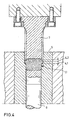
- pinion 1 is shown in longitudinal section, the one has cylindrical base body 2 with at one end an external toothing 3 is provided. As can be seen in FIG. 1 lets, the teeth 4 of the external teeth 3 are so-called Arch teeth formed.
- the component is in the sintering process made from a sintered metallurgical powder.
- FIG. 1 shows the component in the final sintered state.
- 4, 6 and 7 is the method of manufacture 1 based on the workflow in the press tool shown in more detail.
- the pressing tool consists essentially from an essentially encompassing the outer contour Die 5, a lower stamp 6 and an upper form stamp 7.
- the lower stamp 6 is initially filled by a predetermined dimension lowered and the mold space thus formed with sintered metallurgical powder 8 filled.
- the Form stamp 7 lowered, the outer contour 9 substantially corresponds to the inner contour 10 of the upper region of the die 5.
- 3 shows an end view of the die 7.
- the die 7 inserted into the die 5 and simultaneously the lower stamp 6 moves upward, so that the stamp and lower stamps are guided against each other and the only poured powder filling into a solid green compact 1.1 compacted.
- the cylindrical base body 2 already receives its final shape, while the teeth 4 of the external toothing 3 in its lower area 4.1 due to the corresponding Shape of the die 5 already have the curved tooth course, while the upper area 4.2 the contour of a normal one Has straight teeth.
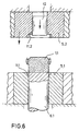
- the intermediate shape of the green compact thus produced is from FIG. 5 seen.
- the green compact 1.1 is in one second work step used in a die 5.1, the has a lower stamp 6.1, and its shape space essentially is formed by a tooth mold space 11.1 which in its geometry corresponds to the area 4.1 on the green compact (FIG. 2).
- An upper die-shaped pressing tool 5.2 is with a Tooth form space 11.2 provided, which is identical to area 4.1 on Green compact (Fig. 5) is formed and which serves the area 4.2 on the green compact, which is also designed as a straight toothing to be reshaped so that this tooth area is the one shown in FIG Receives final contour.
- the upper matrix-shaped - Tool 5.2 is assigned an inner punch 12 so that the Lower stamp 6.1 and the inner stamp 12 when moving together the entire tool assembly can be performed so that apart from the reshaping of the external teeth, no relative displacements of the green body between the two tools 5.1 and 5.2. This pressing situation is shown in Fig. 7.
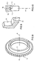
- FIG. 8 shows a perspective view of one Ring 13 with an external toothing 14, as it is for example used as a clutch body in a manual transmission place.
- the individual teeth 15 of the external toothing 14 not designed as normal straight teeth, but have a complicated geometric shape.
- the Tooth flanks 15.1 are shaped as involute surfaces however - as FIG. 10 shows - at an angle to one another.
- the end face 16 is straight, while the End face 17 by two inclined to each other, however flat surface areas 17.1 is formed.
- FIG. 11 is a green compact as a further design example 18 shown for a ring with internal teeth.
- the Green body shown in Fig. 11 is analogous to that based on 2 and 4 described method as the basic component shape manufactured.
- 11 is on a ring body 18.1 only one tooth 19 of the internal toothing in a side view and in Fig. 12 are a plurality of teeth 19 in a processing of the internal toothing shown in a supervision.
- Such a contoured green body can be in one first pressing step analogous to the representation according to FIGS. 2 and 4 produce as basic component shape including the special one Contouring the teeth 19.
- a tooth shape with undercuts as shown in Fig. 13 is shown.
- This tooth shape can be made by a pure one Pressing process because of the undercuts on both sides 20 no longer generate on the tooth flank.
- this is after the inventive method by a forming process possible, which - as indicated in Fig. 14 - by rolling or rolling is possible.
- the green compact 18 is opened held a rotatable counter element 21, for example on a roller or in a support ring.
- the undercuts 20 are then with an appropriately shaped rolling tool 22 as a pressure element that occurs when the counter element rotates 21 rolls on the inner surface of the toothing, by Forming manufactured.
- the undercuts 20 are shown coarsened in FIG. 13. In practical application it is by only slight depressions compared to the adjacent ones Areas of the tooth flanks.
Landscapes
- Engineering & Computer Science (AREA)
- Mechanical Engineering (AREA)
- Manufacturing & Machinery (AREA)
- Powder Metallurgy (AREA)
- Compositions Of Oxide Ceramics (AREA)
- Ceramic Products (AREA)
Description
- Fig. 1
- als Fertigbauteil ein Ritzel mit bogenförmigen Zähnen,
- Fig. 2
- das Füllen der Preßform zur Herstellung des Ritzels gemäß Fig. 1,
- Fig. 3
- eine Stirnansicht eines Formstempels zur Herstellung des Bauteils gemäß Fig. 1,
- Fig. 4
- den ersten Preßschritt,
- Fig. 5
- die Form des im Preßschritt gemäß Fig. 4 geformten Grünlings,
- Fig. 6
- den Grünling gemäß Fig. 5 im Preßwerkzeug durch Durchführung der Umformung,
- Fig. 7
- das Preßwerkzeug gemäß Fig. 6 in Umformposition,
- Fig. 8
- perspektivisch einen Zahnring,
- Fig. 9
- eine Ausschnittvergrößerung für einen Zahn des Zahnrings gemäß Fig. 8,
- Fig. 10
- eine Aufsicht auf den Ausschnitt gemäß Fig. 9,
- Fig. 11
- einen Grünling für einen Zahnring mit hinterschnittener Innenverzahnung nach dem ersten Preßschritt,
- Fig. 12
- eine Abwicklung der Innenverzahnung am Grünling gemäß Fig. 1,
- Fig. 13
- die Innenverzahnung in der Ansicht gemäß Fig. 12 nach der Umformung,
- Fig. 14
- den Umformungspreßvorgang zu Fig. 13.
Claims (5)
- Verfahren zur Herstellung eines gesinterten Zahnrades oder Zahnringes durch Formung eines Grünlings aus einem sintermetallurgischen Pulver, der anschließend gesintert wird, wobei in einem ersten Schritt durch Formpressen aus dem sintermetallurgischen Pulver mittels axial geführter Preßwerkzeuge der Grünling geformt wird mit einer Bauteilgrundform, deren Geometrie im wesentlichen der Bauteilendform entspricht, bis auf Teilbereiche der Zähne, die in den Preßwerkzeugen des ersten Schritts nicht oder nur schwer formbare Geometrien aufweisen, und in wenigstens einem weiteren Schritt mittels gesonderter Umformwerkzeuge durch spanlose Umformung am Grünling die im ersten Preßwerkzeug in ihrer Geometrie nicht endgültig geformten Teilbereiche der Zähne unter Druck in ihre Endform umgeformt werden, so daß der ungesinterte Grünling die Bauteilendform erhält, und danach der Grünling in seiner Bauteilendform zum fertigen Bauteil gesintert wird.
- Verfahren nach Anspruch 1 dadurch gekennzeichnet, daß das Umformen der Teilbereiche durch Pressen und/oder Rollieren erfolgt.
- Verfahren nach Anspruch 1 oder 2, dadurch gekennzeichnet, daß das Umformen stufenweise erfolgt, wobei einzelne Konturen, insbesondere Hinterschneidungen an der Bauteilendform jeweils wenigstens durch eine Umformungsstufe erzeugt werden.
- Verfahren nach einem oder mehreren der Ansprüche 1 bis 3, dadurch gekennzeichnet, daß der Grünling vor wenigstens einem Umformen zur Erhöhung der Grünfestigkeit vorgesintert wird.
- Verfahren nach einem oder mehreren der Ansprüche 1 bis 4, dadurch gekennzeichnet, daß das Bauteil als Grünling vor einem Sintern und/oder als verfestigtes Teil nach einem Sintern kalibriert wird.
Applications Claiming Priority (3)
| Application Number | Priority Date | Filing Date | Title |
|---|---|---|---|
| DE19850326 | 1998-11-02 | ||
| DE19850326A DE19850326A1 (de) | 1998-11-02 | 1998-11-02 | Verfahren zur Herstellung eines gesinterten Bauteils mit Nachverformung des Grünlings |
| PCT/EP1999/008189 WO2000025960A1 (de) | 1998-11-02 | 1999-10-28 | Verfahren zur herstellung eines gesinterten bauteils mit nachverformung des grünlings |
Publications (2)
| Publication Number | Publication Date |
|---|---|
| EP1133374A1 EP1133374A1 (de) | 2001-09-19 |
| EP1133374B1 true EP1133374B1 (de) | 2004-04-14 |
Family
ID=7886330
Family Applications (1)
| Application Number | Title | Priority Date | Filing Date |
|---|---|---|---|
| EP99955898A Expired - Lifetime EP1133374B1 (de) | 1998-11-02 | 1999-10-28 | Verfahren zur herstellung eines gesinterten bauteils mit nachverformung des grünlings |
Country Status (9)
| Country | Link |
|---|---|
| US (1) | US6730263B2 (de) |
| EP (1) | EP1133374B1 (de) |
| JP (1) | JP2002528644A (de) |
| AT (1) | ATE264153T1 (de) |
| AU (1) | AU1266800A (de) |
| CA (1) | CA2348429C (de) |
| DE (2) | DE19850326A1 (de) |
| ES (1) | ES2221459T3 (de) |
| WO (1) | WO2000025960A1 (de) |
Cited By (1)
| Publication number | Priority date | Publication date | Assignee | Title |
|---|---|---|---|---|
| DE102004002714B3 (de) * | 2004-01-19 | 2005-05-19 | SCHWäBISCHE HüTTENWERKE GMBH | Verfahren zum Leichtmetall-Legierungs-Sintern |
Families Citing this family (19)
| Publication number | Priority date | Publication date | Assignee | Title |
|---|---|---|---|---|
| IT1307199B1 (it) * | 1999-06-22 | 2001-10-29 | Mini Gears Spa | Procedimento per la realizzazione di ruote dentate da semilavoratiottenuti per sinterizzazione di polveri metalliche |
| US6946012B1 (en) | 2000-05-18 | 2005-09-20 | Fleetguard, Inc. | Filter and forming system |
| DE10142805C2 (de) * | 2001-08-31 | 2003-10-16 | Gkn Sinter Metals Gmbh | Einteiliger Gelenkkörper |
| DE10203283C5 (de) * | 2002-01-29 | 2009-07-16 | Gkn Sinter Metals Gmbh | Verfahren zur Herstellung von gesinterten Bauteilen aus einem sinterfähigen Material und gesintertes Bauteil |
| FR2866254B1 (fr) * | 2004-02-17 | 2006-06-09 | Fed Mogul Operations France Sa | Procede de fabrication de pieces mecaniques frittees |
| US7237730B2 (en) * | 2005-03-17 | 2007-07-03 | Pratt & Whitney Canada Corp. | Modular fuel nozzle and method of making |
| WO2008073952A2 (en) * | 2006-12-12 | 2008-06-19 | Gkn Sinter Metals, Llc | Powder metal forging and method and apparatus of manufacture |
| JP5922861B2 (ja) * | 2007-02-12 | 2016-05-24 | ジーケーエヌ シンター メタルズ、エル・エル・シー | 金属粉末鍛造物を製造する方法及びその方法によって製造された金属粉末鍛造物 |
| CN101678516A (zh) * | 2007-04-04 | 2010-03-24 | Gkn烧结金属有限公司 | 粉末金属锻件以及制造的方法和设备 |
| US8316541B2 (en) * | 2007-06-29 | 2012-11-27 | Pratt & Whitney Canada Corp. | Combustor heat shield with integrated louver and method of manufacturing the same |
| US7543383B2 (en) | 2007-07-24 | 2009-06-09 | Pratt & Whitney Canada Corp. | Method for manufacturing of fuel nozzle floating collar |
| AT507738B1 (de) * | 2008-12-16 | 2011-03-15 | Miba Sinter Austria Gmbh | Verfahren zur hinterlegung der innenverzahnung einer pulvermetallurgisch hergestellten schiebemuffe für ein schaltgetriebe |
| AT509456B1 (de) * | 2010-08-31 | 2011-09-15 | Miba Sinter Austria Gmbh | Gesintertes zahnrad |
| US9249836B2 (en) | 2013-08-15 | 2016-02-02 | Means Industries, Inc. | Coupling assembly having reduced undesirable noise and contact stress caused by a transition between operating modes of the assembly |
| DE102014110903A1 (de) * | 2014-07-31 | 2016-02-04 | Hoerbiger Antriebstechnik Holding Gmbh | Verfahren zur Herstellung eines Schiebemuffenrings |
| JP6751251B2 (ja) * | 2015-10-15 | 2020-09-02 | セイコーエプソン株式会社 | 三次元造形物の製造方法及び三次元造形物の製造装置 |
| CN209524062U (zh) * | 2019-01-29 | 2019-10-22 | 浙江春风动力股份有限公司 | 一种花键齿、齿轮接合机构及变速箱 |
| CN113646113A (zh) * | 2019-04-24 | 2021-11-12 | 住友电气工业株式会社 | 烧结体的制造方法及压粉成型体 |
| CN114789250B (zh) * | 2022-04-07 | 2024-04-09 | 中国航发北京航空材料研究院 | 一种粉末高温合金圆柱直齿轮构件的制备方法 |
Family Cites Families (24)
| Publication number | Priority date | Publication date | Assignee | Title |
|---|---|---|---|---|
| US2540457A (en) * | 1945-12-05 | 1951-02-06 | Isthmian Metals Inc | Method of making metal articles and products |
| US2542912A (en) * | 1945-12-08 | 1951-02-20 | Ford Motor Co | Process and apparatus for coining sintered articles |
| US3665585A (en) * | 1970-12-04 | 1972-05-30 | Federal Mogul Corp | Composite heavy-duty mechanism element and method of making the same |
| CA1165514A (en) * | 1979-07-09 | 1984-04-17 | William J. Chmura | Thread forming of sintered porous metal shapes |
| JPS5893801A (ja) * | 1981-11-30 | 1983-06-03 | Asahi Denka Kogyo Kk | 粉末焼結物品の製造方法 |
| JPS58181805A (ja) * | 1982-04-15 | 1983-10-24 | Micro Filter Kk | 高緻密シ−ムレスパイプの製造方法 |
| DE3325037C1 (de) * | 1983-07-11 | 1984-07-12 | Sintermetallwerk Krebsöge GmbH, 5608 Radevormwald | Mit wenigstens einer Verzahnung versehener Sintermetallkoerper |
| JPS60141805A (ja) * | 1983-12-28 | 1985-07-26 | Fujitsu Ltd | 焼結丸軸の製造方法 |
| JPS6439304A (en) * | 1987-08-05 | 1989-02-09 | Fujitsu Ltd | Production of iron-cobalt sintered alloy |
| DE3839800A1 (de) * | 1988-11-25 | 1990-05-31 | Sinterstahl Gmbh | Verfahren und vorrichtung zur umformung von zahnflanken pulvermetallurgisch hergestellter kupplungskoerper |
| US5009842A (en) * | 1990-06-08 | 1991-04-23 | Board Of Control Of Michigan Technological University | Method of making high strength articles from forged powder steel alloys |
| US5711187A (en) * | 1990-10-08 | 1998-01-27 | Formflo Ltd. | Gear wheels rolled from powder metal blanks and method of manufacture |
| GB2250227B (en) * | 1990-10-08 | 1994-06-08 | Formflo Ltd | Gear wheels rolled from powder metal blanks |
| US5215946A (en) * | 1991-08-05 | 1993-06-01 | Allied-Signal, Inc. | Preparation of powder articles having improved green strength |
| US5903815A (en) * | 1992-02-12 | 1999-05-11 | Icm/Krebsoge | Composite powdered metal component |
| DE4211319C2 (de) * | 1992-04-04 | 1995-06-08 | Plansee Metallwerk | Verfahren zur Herstellung von Sintereisen-Formteilen mit porenfreier Zone |
| US5390414A (en) * | 1993-04-06 | 1995-02-21 | Eaton Corporation | Gear making process |
| US5563107A (en) * | 1993-04-30 | 1996-10-08 | The Dow Chemical Company | Densified micrograin refractory metal or solid solution solution (mixed metal) carbide ceramics |
| US5659955A (en) * | 1994-01-21 | 1997-08-26 | Plamper; Gerhard | Method of making powder metal helical gears |
| US5762843A (en) * | 1994-12-23 | 1998-06-09 | Kennametal Inc. | Method of making composite cermet articles |
| JP3499370B2 (ja) * | 1996-04-22 | 2004-02-23 | 株式会社日立ユニシアオートモティブ | 焼結冷間鍛造方法 |
| JP3511553B2 (ja) * | 1996-08-02 | 2004-03-29 | 日立粉末冶金株式会社 | 焼結含油軸受の製造方法 |
| US6110419A (en) * | 1997-12-02 | 2000-08-29 | Stackpole Limited | Point contact densification |
| US6044555A (en) * | 1998-05-04 | 2000-04-04 | Keystone Powered Metal Company | Method for producing fully dense powdered metal helical gear |
-
1998
- 1998-11-02 DE DE19850326A patent/DE19850326A1/de not_active Ceased
-
1999
- 1999-10-28 ES ES99955898T patent/ES2221459T3/es not_active Expired - Lifetime
- 1999-10-28 AT AT99955898T patent/ATE264153T1/de not_active IP Right Cessation
- 1999-10-28 CA CA002348429A patent/CA2348429C/en not_active Expired - Fee Related
- 1999-10-28 AU AU12668/00A patent/AU1266800A/en not_active Abandoned
- 1999-10-28 WO PCT/EP1999/008189 patent/WO2000025960A1/de not_active Ceased
- 1999-10-28 JP JP2000579386A patent/JP2002528644A/ja active Pending
- 1999-10-28 EP EP99955898A patent/EP1133374B1/de not_active Expired - Lifetime
- 1999-10-28 DE DE59909201T patent/DE59909201D1/de not_active Expired - Fee Related
-
2001
- 2001-05-02 US US09/847,116 patent/US6730263B2/en not_active Expired - Fee Related
Cited By (1)
| Publication number | Priority date | Publication date | Assignee | Title |
|---|---|---|---|---|
| DE102004002714B3 (de) * | 2004-01-19 | 2005-05-19 | SCHWäBISCHE HüTTENWERKE GMBH | Verfahren zum Leichtmetall-Legierungs-Sintern |
Also Published As
| Publication number | Publication date |
|---|---|
| US6730263B2 (en) | 2004-05-04 |
| WO2000025960A1 (de) | 2000-05-11 |
| ATE264153T1 (de) | 2004-04-15 |
| CA2348429C (en) | 2009-07-28 |
| US20020090314A1 (en) | 2002-07-11 |
| EP1133374A1 (de) | 2001-09-19 |
| DE59909201D1 (de) | 2004-05-19 |
| AU1266800A (en) | 2000-05-22 |
| CA2348429A1 (en) | 2000-05-11 |
| JP2002528644A (ja) | 2002-09-03 |
| DE19850326A1 (de) | 2000-05-04 |
| ES2221459T3 (es) | 2004-12-16 |
Similar Documents
| Publication | Publication Date | Title |
|---|---|---|
| EP1133374B1 (de) | Verfahren zur herstellung eines gesinterten bauteils mit nachverformung des grünlings | |
| DE60036608T2 (de) | Verfahren und vorrichtung zum verdichten von metallpulver-vorformlingen | |
| EP2066468B2 (de) | Verfahren und vorrichtung zur oberflächenverdichtung eines sinterteils | |
| DE60007857T2 (de) | Verfahren zum Verdichten der Wand einer Öffnung eines Rohlings aus metallischem Pulver | |
| AT505947B1 (de) | Verdichtungswerkzeug | |
| WO2011035862A1 (de) | Verfahren zur herstellung eines grünlings | |
| DE19752380A1 (de) | Verfahren zum Herstellen eines Sinterformkörpers, insbesondere eines Zahnriemen- oder Kettenrades | |
| DE2219856B2 (de) | Verfahren zum Herstellen von in einem Arbeitsgang geschmiedeten Sinterschmiedewerkstücken | |
| AT17771U1 (de) | Werkzeug und verfahren zur herstellung eines schrägverzahnten sektorzahnrads und zugehöriges schrägsektorzahnrad | |
| EP0846883A1 (de) | Synchronisationseinrichtung für Getriebe und Verfahren zum Anspitzen von Zähnen eines gesinterten Synchronisationskörpers | |
| AT516779B1 (de) | Verfahren zur Herstellung einer Balligkeit auf einem Sinterbauteil | |
| DE19508952C2 (de) | Preßvorrichtung zur Erzeugung eines Formteils und entsprechendes Formteil | |
| DE3839800C2 (de) | ||
| DE2320336A1 (de) | Vorrichtung zur spanlosen herstellung von kegelzahnraedern aus metallrohteilen | |
| AT521836B1 (de) | Verfahren zum Pressen eines Grünlings | |
| EP0826450B1 (de) | Verfahren zur Kalibrierung einer vorgeformten Ausnehmung | |
| EP2440805B1 (de) | Kalibriervorrichtung und verfahren zum kalibrieren | |
| AT525262B1 (de) | Verfahren zum Pressen eines Grünlings | |
| AT507913B1 (de) | Vorrichtung zum verdichten eines sinterbauteils | |
| EP2834029B1 (de) | Verfahren zur bearbeitung eines funktionsteils | |
| DE102022110166A1 (de) | Schiebemuffe | |
| DE2659733C2 (de) | Verfahren zur Herstellung von Zahnrädern mit zylindrischer Wälzfläche für Laufverzahnungen | |
| DE2544325A1 (de) | Plastisches formverfahren fuer metalle | |
| DE2236383B2 (de) | Verfahren zum Herstellen von Sinterkörpern mit Innengewinde sowie ein Werkzeug zum Durchführen des Verfahrens | |
| DE102018217822B3 (de) | Verfahren zur Herstellung mindestens einer Verzahnung an einem Bauteil und Werkzeug zur Durchführung des Verfahrens |
Legal Events
| Date | Code | Title | Description |
|---|---|---|---|
| PUAI | Public reference made under article 153(3) epc to a published international application that has entered the european phase |
Free format text: ORIGINAL CODE: 0009012 |
|
| 17P | Request for examination filed |
Effective date: 20010428 |
|
| AK | Designated contracting states |
Kind code of ref document: A1 Designated state(s): AT BE CH CY DE DK ES FI FR GB GR IE IT LI LU MC NL PT SE |
|
| AX | Request for extension of the european patent |
Free format text: MK;RO;SI |
|
| 17Q | First examination report despatched |
Effective date: 20011004 |
|
| GRAP | Despatch of communication of intention to grant a patent |
Free format text: ORIGINAL CODE: EPIDOSNIGR1 |
|
| GRAS | Grant fee paid |
Free format text: ORIGINAL CODE: EPIDOSNIGR3 |
|
| GRAA | (expected) grant |
Free format text: ORIGINAL CODE: 0009210 |
|
| AK | Designated contracting states |
Kind code of ref document: B1 Designated state(s): AT BE CH CY DE DK ES FI FR GB GR IE IT LI LU MC NL PT SE |
|
| PG25 | Lapsed in a contracting state [announced via postgrant information from national office to epo] |
Ref country code: NL Free format text: LAPSE BECAUSE OF FAILURE TO SUBMIT A TRANSLATION OF THE DESCRIPTION OR TO PAY THE FEE WITHIN THE PRESCRIBED TIME-LIMIT Effective date: 20040414 Ref country code: IE Free format text: LAPSE BECAUSE OF FAILURE TO SUBMIT A TRANSLATION OF THE DESCRIPTION OR TO PAY THE FEE WITHIN THE PRESCRIBED TIME-LIMIT Effective date: 20040414 Ref country code: FI Free format text: LAPSE BECAUSE OF FAILURE TO SUBMIT A TRANSLATION OF THE DESCRIPTION OR TO PAY THE FEE WITHIN THE PRESCRIBED TIME-LIMIT Effective date: 20040414 Ref country code: CY Free format text: LAPSE BECAUSE OF FAILURE TO SUBMIT A TRANSLATION OF THE DESCRIPTION OR TO PAY THE FEE WITHIN THE PRESCRIBED TIME-LIMIT Effective date: 20040414 |
|
| REG | Reference to a national code |
Ref country code: GB Ref legal event code: FG4D Free format text: NOT ENGLISH |
|
| REG | Reference to a national code |
Ref country code: CH Ref legal event code: EP |
|
| REF | Corresponds to: |
Ref document number: 59909201 Country of ref document: DE Date of ref document: 20040519 Kind code of ref document: P |
|
| REG | Reference to a national code |
Ref country code: IE Ref legal event code: FG4D Free format text: GERMAN |
|
| PG25 | Lapsed in a contracting state [announced via postgrant information from national office to epo] |
Ref country code: GR Free format text: LAPSE BECAUSE OF FAILURE TO SUBMIT A TRANSLATION OF THE DESCRIPTION OR TO PAY THE FEE WITHIN THE PRESCRIBED TIME-LIMIT Effective date: 20040714 Ref country code: DK Free format text: LAPSE BECAUSE OF FAILURE TO SUBMIT A TRANSLATION OF THE DESCRIPTION OR TO PAY THE FEE WITHIN THE PRESCRIBED TIME-LIMIT Effective date: 20040714 |
|
| REG | Reference to a national code |
Ref country code: SE Ref legal event code: TRGR |
|
| GBT | Gb: translation of ep patent filed (gb section 77(6)(a)/1977) |
Effective date: 20040812 |
|
| NLV1 | Nl: lapsed or annulled due to failure to fulfill the requirements of art. 29p and 29m of the patents act | ||
| PG25 | Lapsed in a contracting state [announced via postgrant information from national office to epo] |
Ref country code: LU Free format text: LAPSE BECAUSE OF NON-PAYMENT OF DUE FEES Effective date: 20041028 Ref country code: AT Free format text: LAPSE BECAUSE OF NON-PAYMENT OF DUE FEES Effective date: 20041028 |
|
| PG25 | Lapsed in a contracting state [announced via postgrant information from national office to epo] |
Ref country code: MC Free format text: LAPSE BECAUSE OF NON-PAYMENT OF DUE FEES Effective date: 20041031 Ref country code: LI Free format text: LAPSE BECAUSE OF NON-PAYMENT OF DUE FEES Effective date: 20041031 Ref country code: CH Free format text: LAPSE BECAUSE OF NON-PAYMENT OF DUE FEES Effective date: 20041031 Ref country code: BE Free format text: LAPSE BECAUSE OF NON-PAYMENT OF DUE FEES Effective date: 20041031 |
|
| PGFP | Annual fee paid to national office [announced via postgrant information from national office to epo] |
Ref country code: BE Payment date: 20041124 Year of fee payment: 6 |
|
| REG | Reference to a national code |
Ref country code: IE Ref legal event code: FD4D |
|
| REG | Reference to a national code |
Ref country code: ES Ref legal event code: FG2A Ref document number: 2221459 Country of ref document: ES Kind code of ref document: T3 |
|
| ET | Fr: translation filed | ||
| PLBE | No opposition filed within time limit |
Free format text: ORIGINAL CODE: 0009261 |
|
| STAA | Information on the status of an ep patent application or granted ep patent |
Free format text: STATUS: NO OPPOSITION FILED WITHIN TIME LIMIT |
|
| 26N | No opposition filed |
Effective date: 20050117 |
|
| BERE | Be: lapsed |
Owner name: *GKN SINTER METALS G.M.B.H. Effective date: 20041031 |
|
| REG | Reference to a national code |
Ref country code: CH Ref legal event code: PL |
|
| BERE | Be: lapsed |
Owner name: *GKN SINTER METALS G.M.B.H. Effective date: 20041031 |
|
| PG25 | Lapsed in a contracting state [announced via postgrant information from national office to epo] |
Ref country code: PT Free format text: LAPSE BECAUSE OF NON-PAYMENT OF DUE FEES Effective date: 20040914 |
|
| PGFP | Annual fee paid to national office [announced via postgrant information from national office to epo] |
Ref country code: DE Payment date: 20081029 Year of fee payment: 10 |
|
| PGFP | Annual fee paid to national office [announced via postgrant information from national office to epo] |
Ref country code: ES Payment date: 20081027 Year of fee payment: 10 |
|
| PGFP | Annual fee paid to national office [announced via postgrant information from national office to epo] |
Ref country code: SE Payment date: 20081027 Year of fee payment: 10 Ref country code: IT Payment date: 20081028 Year of fee payment: 10 |
|
| PGFP | Annual fee paid to national office [announced via postgrant information from national office to epo] |
Ref country code: FR Payment date: 20081021 Year of fee payment: 10 |
|
| PGFP | Annual fee paid to national office [announced via postgrant information from national office to epo] |
Ref country code: GB Payment date: 20081024 Year of fee payment: 10 |
|
| EUG | Se: european patent has lapsed | ||
| REG | Reference to a national code |
Ref country code: FR Ref legal event code: ST Effective date: 20100630 |
|
| PG25 | Lapsed in a contracting state [announced via postgrant information from national office to epo] |
Ref country code: FR Free format text: LAPSE BECAUSE OF NON-PAYMENT OF DUE FEES Effective date: 20091102 Ref country code: DE Free format text: LAPSE BECAUSE OF NON-PAYMENT OF DUE FEES Effective date: 20100501 |
|
| PG25 | Lapsed in a contracting state [announced via postgrant information from national office to epo] |
Ref country code: GB Free format text: LAPSE BECAUSE OF NON-PAYMENT OF DUE FEES Effective date: 20091028 |
|
| REG | Reference to a national code |
Ref country code: ES Ref legal event code: FD2A Effective date: 20110303 |
|
| PG25 | Lapsed in a contracting state [announced via postgrant information from national office to epo] |
Ref country code: IT Free format text: LAPSE BECAUSE OF NON-PAYMENT OF DUE FEES Effective date: 20091028 |
|
| PG25 | Lapsed in a contracting state [announced via postgrant information from national office to epo] |
Ref country code: SE Free format text: LAPSE BECAUSE OF NON-PAYMENT OF DUE FEES Effective date: 20091029 |
|
| PG25 | Lapsed in a contracting state [announced via postgrant information from national office to epo] |
Ref country code: ES Free format text: LAPSE BECAUSE OF NON-PAYMENT OF DUE FEES Effective date: 20110302 |
|
| PG25 | Lapsed in a contracting state [announced via postgrant information from national office to epo] |
Ref country code: ES Free format text: LAPSE BECAUSE OF NON-PAYMENT OF DUE FEES Effective date: 20091029 |