EP1133162A2 - Verfahren und Vorrichtung für Wiedergabe der Gradation von Bildern mit kontinuierlichen Tönen - Google Patents
Verfahren und Vorrichtung für Wiedergabe der Gradation von Bildern mit kontinuierlichen Tönen Download PDFInfo
- Publication number
- EP1133162A2 EP1133162A2 EP01301923A EP01301923A EP1133162A2 EP 1133162 A2 EP1133162 A2 EP 1133162A2 EP 01301923 A EP01301923 A EP 01301923A EP 01301923 A EP01301923 A EP 01301923A EP 1133162 A2 EP1133162 A2 EP 1133162A2
- Authority
- EP
- European Patent Office
- Prior art keywords
- gradation
- amplitude
- threshold values
- error
- data
- Prior art date
- Legal status (The legal status is an assumption and is not a legal conclusion. Google has not performed a legal analysis and makes no representation as to the accuracy of the status listed.)
- Granted
Links
Images


Classifications
-
- H—ELECTRICITY
- H04—ELECTRIC COMMUNICATION TECHNIQUE
- H04N—PICTORIAL COMMUNICATION, e.g. TELEVISION
- H04N1/00—Scanning, transmission or reproduction of documents or the like, e.g. facsimile transmission; Details thereof
- H04N1/40—Picture signal circuits
- H04N1/40087—Multi-toning, i.e. converting a continuous-tone signal for reproduction with more than two discrete brightnesses or optical densities, e.g. dots of grey and black inks on white paper
Definitions
- the present invention relates to a method and apparatus for gradation reproduction of continuous tone images in which the gray scale of a continuous tone image is converted into multiple levels of three or more.
- printers with a type expressing one dot by the existence/nonexistence of ink i.e., by binary expression.
- printers which print one dot by selectively using light and dark inks or by changing the dot size i.e., printers of a type expressing one dot by multivalue expression.
- Printers of this type can express gradation change more smoothly in comparison with those using binary expression, and also have the advantage of making dots in a highlight portion inconspicuous.
- multivaluing processing for converting the gray scale of an original image into not two levels but multiple levels (at least three levels) is required.
- input image data to be multivalued have a sufficiently large number of gray-scale levels (e.g., 256 levels).
- Multiple values of multivaluing are a number of values larger than 2, e.g., 3.
- a error diffusion method uses a process in which, when an input image data is multivalued, an error caused between the state before multivaluing and the state after multivaluing is diffused in subsequent data on the basis of proportions according to weight coefficients. According to the error diffusion method, a gray-scale error caused at the time of multivaluing is eliminated by being spread to neighbor pixels, thereby improving the reproducibility of a continuous tone image.
- a gradation reproduction apparatus described in Japanese Patent Laid-Open Publication No. 11-17946 (hereinafter referred to as conventional art) is known as an apparatus for carrying out a continuous tone image gradation reproduction method based on a multivaluing-error diffusion method such as that described above.
- the conventional art described in the above-mentioned publication includes an example of 3-valuing as multivaluing, which is described as a process in which input image data on each of the pixels expressed by, for example, 256 values (value 0 to value 255) supplied from an unillustrated host computer is converted into a 3-value data (a kind of multivalue data) expressed by, for example, white [0], gray [1], and black [2].
- the conventional art 21 includes, in a basic arrangement according to a gradation reproduction method based on a 3-valuing error diffusion method, an adder 22 for correcting input image data on a particular pixel (target pixel) by adding a corrected error to form corrected data, a 3-valuing section 23 for three-valuing the corrected data obtained by the adder 22 by using two threshold values, a 3-value memory 24 for storing 3-value data obtained by the 3-valuing section 23, an error detection section 25 for detecting an error between the correction data and the 3-value data with respect to the target pixel, an error spreader 26 for spreading the error detected by the error detection section 25 to unprocessed pixels (neighbor pixels) positioned near the target pixel on the basis of weight coefficients which determine how the error is spread to the neighbor pixels, and an error memory 27 for accumulating errors determined by the error spreader 26 with respect to each pixel, and thereafter transferring the accumulated errors as a corrected error to the adder 22.
- the 3-valuing section 23 3-values corrected data by using two threshold values, e.g., a first threshold value of 64 and a second threshold value of 192.
- the value 64 is an intermediate value between the value 0 and the value 128, and the value 192 is an intermediate value between the value 128 and the value 255.
- the 3-valuing section 23 selects white [0] in 3-value data when the corrected data is equal to or smaller than the value 63, selects gray [1] when the corrected data is in the range from the value 63 to the value 192, and selects black [2] in 3-value data when the corrected data is equal to or larger than the value 193.
- the above-mentioned input image data is expressed by, for example, the values 0 to 255 as mentioned above, the above-described corrected data may have a value smaller than 0 and a value exceeding the value 255 since a corrected error is added to the input image data.
- Corrected errors transferred from the error memory 27 to the adder 22 appear in a vibrating manner with variations in magnitude. Accordingly, corrected data formed by adding the corrected errors to the input image data also appear in a vibrating manner with the same amplitude as the corrected errors.
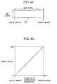
- Fig. 44 is a plan view of a test image 29.
- the test image 29 has a matrix of 256 dots horizontally by 64 dots vertically, and has continuous gradation from solid black to solid white in the horizontal direction.
- Fig. 45 is a diagram showing the distribution of data values of the test image 29 shown in Fig. 44.
- the abscissa represents the position in the horizontal direction on the test image 29 shown in Fig. 44
- the ordinate represents the gray scale of the test image 29 by 256 data values in the range from the value 0 to the value 255, the value 255 representing solid black, the value 0 representing solid white.
- the gradation in the test image 29 shown in Fig. 44 is reproduced by 3-valuing using the above-described basic arrangement of the conventional art 21 shown in Fig. 43. Since the two threshold values for 3-valuing are the values 64 and 192, which are fixed threshold values widely spaced apart, vibrating corrected data falls into the range between the two threshold values, and no data item spikes outward beyond the two threshold values.
- Fig. 46 is a plan view schematically showing a reproduced image obtained in the above-described manner.
- the reproduced image shown in Fig. 46 has a gradation reproduction region 31 in which gradations are reproduced by white dots and gray dots from a solid white portion to a certain light gradation, and a gradation reproduction region 32 in which gradations are reproduced by black dots and gray dots from a solid black portion to a certain dark gradation.
- a solid gray region 33 is formed at a halftone gradation at a position between the solid white portion and the solid black portion.
- the solid gray region 33 is recognized as a contour which does not exist originally. As a result, a gradation discontinuity is caused.
- Fig. 47 is a diagram in which the reproduced image shown in Fig. 46 is expressed by a dot distribution. As shown in the dot distribution diagram shown in Fig. 47, a region is formed in which there are no black dots BL and no white dots WH at the halftone gradation, and in which only gray dots GR exist.
- an in-window pixel checking section 28 is added to the basic arrangement in the conventional art 21, as shown in Fig. 43.
- the in-window pixel checking section 28 checks whether all the items of 3-value data on a plurality of pixels existing in a predetermined window (indicated by hatching in symbol 28 in Fig. 43) in the 3-value data memory 24 are gray [1].
- the 3-valuing section 23 performs ordinary 3-valuing processes described above, that is, 3-valuing using the threshold value 64 and the threshold value 192.
- the 3-valuing section 23 performs special 3-valuing processing, that is, it changes the two threshold values so that the interval therebetween is reduced. More specifically, it substitutes the value 120 for the threshold value 64, and substitutes the value 136 for the threshold value 192.
- the 3-valuing section 23 selects white [0] in 3-value data when the corrected data is equal to or smaller than the value 119, selects gray [1] when the corrected data is in the range from the value 120 to the value 136, and selects black [2] in 3-value data when the corrected data is equal to or larger than the value 137.
- the probability of occurrence of gray [1] as a result of 3-valuing is reduced and occurrences of white [0] and black [2] are increased, so that the vibrating corrected data spikes outward beyond the two threshold values with respect to the halftone gradation. Consequently, the corresponding 3-valuing results consist of not only gray [1] but also white [0] and black [2], and, at the time of printing (image reproduction), gray dots, white dots and black dots are suitably mixed and no solid gray such as that described above (see symbol 33 in Fig. 27) occurs, thus achieving continuous gradation even at the halftone gradation.
- the interval between the two threshold values is reduced if it is determined that all the items of 3-value data on a plurality of pixels in the predetermined window in the 3-value data memory 24 are gray [1].
- a main object of the present invention is to provide a method and apparatus for gradation reproduction of continuous tone images having a determination criterion for reliably setting suitable threshold values ensuring continuity at the halftone gradation.
- Another object of the present invention is to provide an apparatus for gradation reproduction of continuous tone images free from the need for ascertainment as to whether all items of multivalue data in a predetermined range are the same, and using a simple algorithm.
- a method for gradation reproduction of a continuous tone image based on a error diffusion method in which, when the gradation of input image data on a continuous tone image is converted into multivalue data based on multiple values which are at least three values by using at least two sets of threshold values to reproduce a gradation, an error between a data item before multivaluing and the corresponding multivalued data item is spread, as a corrected error, under spreading conditions determined by weight coefficients, to a plurality of subsequent data items successively input to obtain corrected data, and the corrected data is multivalued, the gradation reproduction method comprising determining the interval between the threshold values so that the amplitude of the corrected data according to rising and falling variations in the corrected error spikes outward beyond the threshold values at least at a halftone gradation between a darkest gradation and a lightest gradation, whereby generation of a transient region is prevented where the amplitude of the corrected data becomes excessively small at the half
- the method for gradation reproduction of a continuous tone image produces the amplitude of the corrected error depending upon the spreading conditions according to the weight coefficients, and determines the interval between the threshold values so that the amplitude spikes outward beyond the threshold values at least at the halftone gradation.
- the method for gradation reproduction of a continuous tone image determines the threshold values according to the gradation of the input image data by referring to a threshold value look-up table in which the interval between the threshold values according to the weight coefficients is determined in advance, and in which the threshold values according to the gradation of the input image data are set in advance, and inputs the input image data to the threshold value look-up table, and the look-up table determines the threshold values according to the gradation of the input image data.
- the method for gradation reproduction of a continuous tone image sets the amplitude of the pseudo-random numbers so that the amplitude does not exceed a certain limit value, makes the amplitude variable according to the value of input image data, makes the amplitude zero when the value of input image data is zero or at the maximum of the dynamic range, and makes the amplitude smoothly changeable with respect to the input image data.
- the method for gradation reproduction of a continuous tone image determines the amplitude of the pseudo-random numbers by referring to an amplitude limit value look-up table in which limit values of the amplitude of the pseudo-random numbers according to the input image data are set in advance.
- Figs. 1 through 5 show an embodiment mode of implementation of the apparatus for gradation reproduction of continuous tone images in accordance with the present invention.
- the image processing system has, as shown in Fig. 2, a host computer 1, and a printer 2 connected to the host computer 1.
- the host computer 1 transfers data on an original image to the printer 2.
- original image data transferred from the host computer 1 is image data read in by an unillustrated image scanner, image data stored in storage means of the host computer 1, or image data such as computer graphics artificially made in the host computer 1.
- the printer 2 has an image data input means 3 which is supplied with original image data from the host computer 1, and which expresses image data (input image data) in multiple gradation steps such as, for example, 256 values (value 0 to value 255) with respect to each pixel, a 3-valuing processing means 4 which is supplied with image data transferred from the image data input means 3, which converts the supplied image data into 3-value data (3-valued as, for example, white [0], gray [1], and black [2]), and which corresponds to the gradation reproduction apparatus in this embodiment mode, and a 3-value data printing means 5 for performing printing (gradation reproduction) on the basis of 3-value data output from the 3-valuing processing means 4.
- image data input means 3 which is supplied with original image data from the host computer 1, and which expresses image data (input image data) in multiple gradation steps such as, for example, 256 values (value 0 to value 255) with respect to each pixel
- a 3-valuing processing means 4 which is supplied with image data transferred from the image data input means
- Fig. 1 shows the configuration of the 3-valuing processing means 4 (gradation reproduction apparatus).
- the 3-valuing processing means 4 has, as components in a basic arrangement for gradation reproduction based on a 3-valuing error diffusion method, an adder 13 for adding pseudo-random numbers FN to input image data IN on a target pixel input from the host computer 1 (see Fig.
- a pseudo-random number section 12 for generating pseudo-random numbers FN
- an adder 6 for correcting the input image data IN, to which pseudo-random numbers FN have been added, by adding a corrected error ME to form corrected data MI
- a 3-valuing section 7 for three-valuing the corrected data MI obtained by the adder 6 by using two sets of threshold values
- an error computation section 8 for computing an error between the corrected data MI about the target pixel and the 3-value data about the target pixel three-valued by the 3-valuing section 7, an error diffusing section 9 for spreading the error computed by the error computation section 8 to neighbor pixels according to predetermined weight coefficients, and an error memory 10 for accumulating errors spread by the error diffusing section 9 with respect to each pixel and thereafter transferring the accumulated errors as a corrected error ME to the adder 6.
- the weight coefficients used in error diffusing by the error diffusing section 9 designate the bounds of neighbor pixels to which an error is spread, and proportions of values respectively spread to neighbor pixels when an error is spread to the respective pixels.
- the errors accumulated on the pixels A to F in the error memory 10 are transferred to the adder 6 to be added as corrected error ME to the input image data IN.
- the 3-valuing processing means 4 is provided with a threshold value look-up table (hereinafter referred to as "threshold value LUT") 11 which is referred to when the magnitude of the two sets of threshold values and the interval between the two sets of threshold values are determined.
- threshold value LUT threshold value look-up table
- threshold value sets each consists of 256 threshold values are defined with respect to 256 values, the values 0 to the value 255, and 3-valuing is performed by using the two sets of threshold values.
- the amplitude of the above-described corrected error depends on the configuration of the above-described weight coefficients. That is, if the number of neighbor pixels to which an error is spread is larger, the amplitude of the corrected error is reduced.
- the 3-value data printing means 5 is arranged to express shades of an image by lightness and darkness of dots. Black is expressed by dark dots, gray is expressed by light dots, and white is expressed by the absence of dots. In the following description, a dark dot is referred to “black dot”, a light dot is referred to as “gray dot”, and the absence of a dot is referred to as “white dot”.
- [0] of 3-value data corresponds to a white dot
- [1] corresponds to a gray dot
- [2] corresponds to a black dot.
- an original image is sectioned into pixels arranged in rows and columns, and each pixel is expressed by one of the rows arranged in the vertical direction and one of the columns arranged in the horizontal direction.
- the 3-valuing processing means 4 starts reading from the pixel in the row 0 and in the column 0 (Step 1 in Fig. 3) and reads in input image data Pij on the pixel (target pixel) in the row i and in the column j (Step 2). Then, pseudo-random numbers generated by the pseudo-random number section are added to the read in input image data (Step 3).
- Step 4 spread and accumulated errors related to the target pixel are read from the error memory 10 as a corrected error from the neighbor pixels of the target pixel.
- the adder 6 adds the corrected error read in from the error memory 10 to the input image data Pij of the target pixel to correct the input data, thereby computing corrected data (Step 5).
- the threshold value LUT 11 computes two threshold values according to the input image data Pij on the target pixel (Step 6).
- the corrected data and the two threshold values are compared and the corrected data is three-valued to be obtained as 3-value data (Step 7).
- an error Eij produced by comparing the corrected data and the 3-value data is computed (Step 8).
- the error diffusing section 9 spreads the error Eij to the neighbor pixels according to the predetermined weight coefficients, and updates the contents of the error memory 10 by storing the error for each pixel (Step 9).
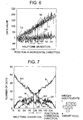
- Fig. 4 is a graph for explaining various parameters in the above-described 3-valuing processing means 4 (see Fig. 1), showing, as parameters, two sets of threshold values T1 and T2, input image data IN, corrected error ME, and corrected data MI.
- the values of the parameters are examined and indicated with respect to processing of dots in one horizontal line passing a center of the image in order to avoid transient influence.
- Corrected data MI is the result of addition of corrected error ME to the input image data IN.
- the corrected data MI is 3-valued by being compared with thresholds values T1 and T2.
- thresholds values T1 and T2 As a form of the threshold values, a form of monotonously increasing with the input image data is used by way of example. However, the interval between the two threshold values is essential and the threshold values of the present invention are not limited to this example.
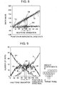
- Fig. 5 is a dot distribution diagram showing a distribution of black dots BL, gray dots GR, and white dots WH based on the parameters shown in Fig. 4.
- the interval between the threshold values T1 and T2 is set so that variations in corrected data MI with an amplitude in the vertical direction (same as the amplitude of corrected error ME) spike outward beyond the two sets of threshold values T1 and T2.
- the effect of this setting is that, at the halftone gradation of corrected data MI, black below the threshold value T1, gray between the threshold values T1 and T2, and white above the threshold value T2 are suitably distributed.
- black dots BL, gray dots GR, and white dots WH are suitably mixed at the halftone gradation, so that no solid gray is generated and continuous reproduced gradation is realized.
- Embodiment 1 will be described with reference to Figs. 6, 7 and 1.
- the weight coefficients are in a configuration A shown in Fig. 7, and the number of neighbor pixels to which an error is spread is 6 (an asterisk denotes a target pixel).
- the amplitude of corrected error ME depends on the configuration of the weight coefficients A. If the number of neighbor pixels to which an error is spread is comparatively small as in the case of the weight coefficients A, the amplitude of the corrected error ME is comparatively large, as shown in Fig. 6.
- threshold LUT 11 In the threshold LUT 11 (see Fig. 1), two sets of threshold values T1 and T2 are set so that the interval therebetween is constant and is sufficiently smaller than the amplitude of corrected data MI (same as the amplitude of corrected error ME).
- the interval between the threshold values T1 and T2 is smaller than the amplitude of corrected data MI at the halftone gradation, and 3-valuing is performed so that black, gray and white are suitably distributed at the halftone gradation, thereby preventing generation of a transient region (see symbol TR in Fig. 10) where the amplitude is excessively small at the halftone gradation of corrected data MI.
- black dots BL, gray dots GR, and white dots WH are suitably mixed at the halftone gradation, so that no solid gray is generated and continuous reproduced gradation is realized.
- Embodiment 1 however, the amplitude of corrected data ME is larger than the interval between the threshold values T1 and T2, in contrast with that in the embodiment mode shown in Figs. 4 and 5. Therefore, the proportion of gray dots GR in Embodiment 1 shown in Fig. 7 is smaller than that of the gray dots GR in the above-described embodiment mode shown in Fig. 5. Since the proportion of gray dots GR is somewhat reduced, it can be said that the effect of Embodiment 1 in terms of effective use of gray dots is slightly lower than that in the above-described implementation mode.
- Embodiment 2 will be described with reference to Figs. 8 and 9.
- the weight coefficients are in a configuration B shown in Fig. 9, and the number of neighbor pixels to which an error is spread is 12. If, as in the case of the weight coefficients B, the number of neighbor pixels to which an error is spread is larger than that in the case of the weight coefficients A in Embodiment 1, the amplitude of corrected error ME shown in Fig. 8 is smaller than that in Embodiment 1 (see Fig. 6). On the other hand, the interval between the two sets of threshold values T1 and T2 is the same as that in Embodiment 1 (see Fig. 6), as shown in Fig. 8.
- the interval between the two sets of threshold values T1 and T2 is smaller than the amplitude of corrected data MI, and no transient region (see symbol TR in Fig. 10) is generated at the halftone gradation. Therefore, as shown in Fig. 9 black dots BL, gray dots GR, and white dots WH are suitably mixed at the halftone gradation, so that no solid gray is generated and continuous reproduced gradation is realized.
- the weight coefficients are in a configuration C shown in Fig. 11, and the number of neighbor pixels to which an error is spread is 20. If, as in the case of the weight coefficients C, the number of neighbor pixels to which an error is spread is larger than that in the case of the weight coefficients B in Embodiment 2, the amplitude of corrected error ME is further smaller than that in Embodiment 2 (see Fig. 8), as shown in Fig. 10.
- the interval between threshold values T1 and T2 is set to the same value as those in Embodiment 1 (see Fig. 6) and Embodiment 2 (see Fig. 8).
- the amplitude of corrected error ME depends on the configuration of weight coefficients A, B, or C.
- Embodiment 3 will be described with reference to Figs. 12 and 13.
- Embodiment 3 relates to a case where the interval between threshold values T1 and T2 is excessively small in comparison with the amplitude of corrected error ME.
- the interval between threshold values T1 and T2 is further reduced relative to the amplitude of corrected data MI and in comparison with that in Embodiment 1. Therefore, the gradation reproducibility is further reduced in comparison with Embodiment 1.
- the interval between threshold values T1 and T2 is suitably set without being excessively reduced relative to the amplitude of corrected error ME, thereby suitably mixing black, white and gray at the halftone gradation.
- Embodiment 4 will be described with reference to Figs. 14 and 15.
- the interval between threshold values T1 and T2 is set as defined by curved lines which are substantially largely spaced apart at the opposite ends corresponding to the black gradation and the white gradation, but which are brought closer to each other at the center corresponding to the halftone gradation.
- the interval between threshold values T1 and T2 is smaller than the amplitude of corrected error ME at the halftone gradation. Therefore, no transient region is generated, black dots BL, white dots WH and gray dots GR are suitably mixed, and the reproduced gradation is continuous, as shown in Fig. 15.
- the interval between threshold values T1 and T2 is set as defined by lines curved reversely relative to those in Embodiment 4, that is, the interval between threshold values T1 and T2 is maximized at the center corresponding to the halftone gradation, and is minimized at the opposite ends corresponding to the black gradation and the white gradation.
- Fig. 18 is a plan view of a test image 40.
- the test image 40 has a 256 by 64 matrix of dots, and the values of all the pixels are the same and correspond to the halftone gradation, that is, the pixel value is set to a constant value of 128.
- Fig. 19 shows an area formed by 32 ⁇ 32 pixels when the test image 40 shown in Fig. 18 is 3-valued.
- a hatched pixel corresponds to a gray dot [1]. That is, an image having a constant value corresponding to the halftone gradation is expressed by gray dots [1] alone to have a result different from a mixture of white dots [0], gray dots [1] and black dots [2] in a continuous-gradation image.
- a pseudo-random number section 12 is provided to obtain pseudo-random numbers FN.
- Fig. 20 is a block diagram showing the configuration of the pseudo-random number section 12.
- the pseudo-random number section 12 is constituted of a pseudo-random number generation section 14 and an amplitude limit section 15.
- a well-known method for generating pseudo-random numbers may be used as a method of generating pseudo-random numbers in the pseudo-random number generation section 14.
- the maximum amplitude of generated pseudo-random numbers is limited in the amplitude limit section 15.
- Pseudo-random numbers obtained in the pseudo-random number section 12 are added to input image data IN by the adder 13.
- the input image data to which the pseudo-random numbers have been added thereafter undergoes the same process to be 3-valued.
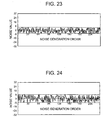
- Figs. 21 through 24 are diagrams for explaining pseudo-random numbers generated in the pseudo-random number section.
- the abscissa represents the order of generation of pseudo-random numbers, and the ordinate represents the values of pseudo-random numbers.
- Fig. 21 shows a case where the maximum amplitude is 0, that is, there are no pseudo-random numbers;
- Fig; 22 shows a case where the maximum amplitude is 4;
- Fig. 23 shows a case where the maximum amplitude is 6;
- Fig. 24 shows a case where the maximum amplitude is 8.
- the amplitude referred to in this description is the maximum of the distance from the center of vibration to peaks of vibration.
- a wiggly line indicates the maximum amplitude.
- pseudo-random numbers are generated substantially randomly with amplitudes within the limits of the maximum amplitude.
- the limitation of the amplitude in the amplitude limit section may be performed based on a known method, e.g., a method of dividing pseudo-random numbers generated in the pseudo-random number generation section by the value of the limit amplitude, and removing the remainder. In this case, the positive/negative of the original pseudo-random numbers is preserved through the amplitude limiting processing.
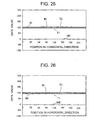
- Figs. 25 through 28 are graphs for explaining various parameters in the 3-valuing processing means 4 (see Fig. 1) with respect to the image 30, as is Fig. 4.
- Fig. 25 shows a case where the amplitude of pseudo-random numbers is zero, that is, no pseudo-random numbers are added. In this case, all the values are steady and corrected data MI is always within the range between threshold values T1 and T2, so that only gray dots [1] are outputted.
- Threshold values T1 and T2 are also variable with respect to input image data, as are those in the case shown in Fig. 4. However, since the input image data is constant, threshold values T1 and T2 shown in Fig. 25 are also fixed.
- Fig. 26 shows a case where the amplitude of pseudo-random numbers is 4, the pseudo-random numbers are added to input image data IN to cause vibration in input image data IN, and vibration is also caused in corrected error ME and corrected data MI.
- corrected data MI is within the range between threshold values T1 and T2, only gray dots [1] are outputted.
- Figs. 27 and 28 respectively show a case where the amplitude of pseudo-random numbers is 6, and a case where the amplitude of pseudo-random numbers is 8.
- input image data IN vibrates largely, so that corrected error ME and corrected data MI also vibrate largely.
- corrected data MI exceeds threshold values T1 and T2, thereby generating white dots [0] and black dots [2] as well as gray dots [1].
- Figs. 29 and 30 show in the 32 x 32 area the results of 3-valuing of the image shown in Fig. 18 with respect to use of the pseudo-random numbers shown in Figs. 23 and 24.
- hatched pixels are gray dots [1]
- pixels shown in white are white dots [0]
- pixels shown in black are black dots [2].
- it is possible to generate a mixture of gray dots [1], white dots [0] and black dots [2] by adding pseudo-random numbers of a certain magnitude to input image data.
- amplitude 6 shown in Fig. 23 is set, white dots [0] and black dots [2] are unevenly mixed with gray dots [1].
- amplitude 8 shown in Fig. 24 white dots [0] and black dots [2] are suitably mixed with gray dots [1] and the result is similar to that in the case of a continuous-tone image.
- Figs. 31 and 32 show in the 32 ⁇ 32 area the results of 3-valuing of a constant-zero-value image.
- Fig. 31 shows the result of 3-valuing without adding pseudo-random numbers.
- Fig. 32 is a plan view of the result in the case where pseudo-random numbers with amplitude 8 are added to input image data. In this case, gray dots [1] are generated among white dots [0]. It is desirable that, after 3-valuing, only white dots [0] should be reproduced with respect to an image originally having only a constant zero value. However, in this embodiment, there is a problem in that unnecessary dots, which may reduce the image quality, are generated as a result of addition of pseudo-random numbers.
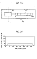
- Fig. 33 is a block diagram showing the configuration of the amplitude limit section 15.
- the amplitude limit section 15 is constituted of an amplitude conversion section 16 and an amplitude table 17.
- the values of limit amplitudes of pseudo-random numbers with respect to the value of input image data are stored. That is, amplitude limit values consisting of 256 values are stored by being respectively related to 256 values, i.e., values 0 to 255 of input image data.
- the amplitude of pseudo-random numbers is converted by using a limit amplitude value obtained by referring to the amplitude table 17 based on the value of the input image data.
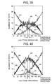
- Figs. 34 and 35 are diagrams showing examples of the amplitude table.
- the abscissa represents the value of input image data, and the ordinate represents the amplitude limit value.
- the amplitude limit value is zero, that is, there are no pseudo-random numbers.
- the amplitude limit value is 8 and the maximum of pseudo-random numbers is 8.
- no pseudo-random numbers are generated and a reproduction result, such as shown in Fig. 31, is obtained. Unnecessary dots are not generated.
- Fig. 35 is a diagram for explaining another example of the amplitude table.
- the amplitude of pseudo-random numbers is zero, and the vibration value and the inclination are continuously changed from each of these points. Therefore, no discontinuity is caused even when a continuous-gradation image is reproduced. Also, an image can be reproduced without occurrence of unnecessary dots.
- halftone gradation data can be reproduced so that white dots [0], gray dots [1] and black dots [2] exist mixedly, the gradation can be smoothly expressed, and, with respect to expression of solid white or solid black, reproduction of unnecessary dots is prevented. Further, a continuous-gradation image can be reproduced without a discontinuity. Thus, improved gradation reproduction can be achieved.
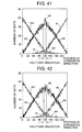
- Figs. 39, 40, and 41 are dot distribution diagrams similar to Fig. 5, which were obtained by setting threshold value intervals of 18, 24, and 28, respectively.
- the proportion of gray dots [1] in the halftone-gradation portion becomes higher if the interval between the threshold values is increased. Also, the proportion of gray dots [1] in the halftone-gradation portion becomes lower if the interval between the threshold values is reduced.
- a case where the interval between the threshold values is sufficiently wide corresponds to the conventional error diffusion method extended to 3-valuing as shown in Fig. 47. In such a case, an image portion is formed where only gray dots [1] are formed.
- a case where there is no interval between the threshold values corresponds to the conventional binary error diffusion method using one threshold value, i.e., a case where no gray dots [1] are formed.
- gradation reproduction is performed by using three kinds of dots: white dots [0], gray dots [1] and black dots [2], it is desirable that, to effectively utilize the existence of gray dots [1], the proportion of gray dots [1] in the halftone-gradation portion is increased as high as possible, and that occurrence of a solid gray region is prevented as in the case of the conventional error diffusion method expended to 3-valuing.
- the maximum amplitude of pseudo-random numbers is slightly increased with respect to the median of the dynamic range of the input value or a value close to the median.
- Fig. 36 is a diagram showing an example of an amplitude limit value in accordance with the present invention.
- the abscissa represents the value of input image data and the ordinate represents the amplitude limit value.
- the maximum amplitude of pseudo-random numbers is slightly increased with respect to the median of the dynamic range of the input value or a value close to the median. More specifically, in this example, the amplitude limit value is set to 9 only when the input image data value is 127 and when it is 128.
- Fig. 42 is a dot distribution diagram showing dot generation proportions in this example.
- the amplitude limit value is slightly increased with respect to the median of the dynamic range of the input value or a value close to the median to slightly increase the pseudo-random number value.
- the input data value is thereby caused to vary more largely, so that the instability of occurrence of gray dots [1] is slightly increased and the proportion is reduced. As a result, a dot distribution such as shown in Fig. 42 is obtained. In a dot distribution such as shown in Fig. 42, the proportion of gray dots [1] is high, the distributions of white dots [0] and black dots [2] do not break, and the continuity of gradation reproduction is maintained, thus achieving visually favorable gradation reproduction.
- Figs. 37 and 38 are diagrams showing other examples of the amplitude limit value in accordance with the present invention.
- Fig. 37 shows a case where the extent to which the maximum amplitude of pseudo-random numbers is slightly increased in comparison with the case shown in Fig. 36.
- the amplitude limit value is set to 9.
- the input image data value is 128, the amplitude limit value is set to 10.
- Fig. 38 shows a case where a plurality of input image data values are set at which the maximum amplitude of pseudo-random numbers is slightly increased.
- the amplitude limit value is set to 9.
- a computation section (not shown) may be separately provided to compute the magnitude and the interval of threshold values T1 and T2 according to input image data and weight coefficients.
- threshold value LUT 11 is provided as described in the embodiment mode, there is no need to make computation, so that the processing can be simplified.
- a error diffusion method in a narrow sense i.e., a method of spreading an error caused with respect to a target pixel to unprocessed neighbor pixels according to predetermined weight coefficients
- the present invention can also be applied to a two-level error diffusion method in which errors of a plurality of processed pixels are accumulated on the basis of predetermined weight coefficients to obtain a correction value.
- the error diffusion method in the present invention comprises error diffusion methods in a broad sense including a two-level error diffusion method as well as a error diffusion method in a narrow sense.
- the apparatus and method for gradation reproduction of continuous tone images have advantages described below.
Landscapes
- Physics & Mathematics (AREA)
- Discrete Mathematics (AREA)
- General Physics & Mathematics (AREA)
- Engineering & Computer Science (AREA)
- Multimedia (AREA)
- Signal Processing (AREA)
- Image Processing (AREA)
- Facsimile Image Signal Circuits (AREA)
- Color, Gradation (AREA)
- Image Input (AREA)
Applications Claiming Priority (6)
| Application Number | Priority Date | Filing Date | Title |
|---|---|---|---|
| JP2000062411 | 2000-03-07 | ||
| JP2000062411 | 2000-03-07 | ||
| JP2000138695 | 2000-05-11 | ||
| JP2000138695 | 2000-05-11 | ||
| JP2001040590 | 2001-02-16 | ||
| JP2001040590A JP4335467B2 (ja) | 2000-03-07 | 2001-02-16 | 濃淡画像の階調再現方法および装置 |
Publications (3)
| Publication Number | Publication Date |
|---|---|
| EP1133162A2 true EP1133162A2 (de) | 2001-09-12 |
| EP1133162A3 EP1133162A3 (de) | 2003-02-26 |
| EP1133162B1 EP1133162B1 (de) | 2007-04-11 |
Family
ID=27342598
Family Applications (1)
| Application Number | Title | Priority Date | Filing Date |
|---|---|---|---|
| EP01301923A Expired - Lifetime EP1133162B1 (de) | 2000-03-07 | 2001-03-02 | Verfahren und Vorrichtung für Wiedergabe der Gradation von Bildern mit kontinuierlichen Tönen |
Country Status (4)
| Country | Link |
|---|---|
| US (1) | US7034964B2 (de) |
| EP (1) | EP1133162B1 (de) |
| JP (1) | JP4335467B2 (de) |
| DE (1) | DE60127745T2 (de) |
Cited By (3)
| Publication number | Priority date | Publication date | Assignee | Title |
|---|---|---|---|---|
| EP1331804A2 (de) | 2002-01-24 | 2003-07-30 | Ricoh Company, Ltd. | Bilderzeugungsvorrichtung und -verfahren, Computerprogramm und Aufzeichnungsmedium |
| US8204334B2 (en) | 2006-06-29 | 2012-06-19 | Thomson Licensing | Adaptive pixel-based filtering |
| US8467626B2 (en) | 2006-09-29 | 2013-06-18 | Thomson Licensing | Automatic parameter estimation for adaptive pixel-based filtering |
Families Citing this family (16)
| Publication number | Priority date | Publication date | Assignee | Title |
|---|---|---|---|---|
| JP2000287086A (ja) * | 1999-03-31 | 2000-10-13 | Minolta Co Ltd | 画像処理装置 |
| JP3945976B2 (ja) * | 2000-11-21 | 2007-07-18 | 富士フイルム株式会社 | 画像表示方法及び装置 |
| US6992789B2 (en) * | 2001-06-15 | 2006-01-31 | International Business Machines Corporation | Method, system, and program for managing a multi-page document |
| US7268919B2 (en) * | 2002-01-17 | 2007-09-11 | Seiko Epson Corporation | Image data processing apparatus, method, and program that diffuses gradiation error for each pixel in target block |
| JP2004206686A (ja) * | 2002-12-12 | 2004-07-22 | Fuji Photo Film Co Ltd | 画像処理装置および画像処理プログラム |
| KR100552908B1 (ko) * | 2003-12-16 | 2006-02-22 | 엘지전자 주식회사 | 플라즈마 디스플레이 패널의 구동방법 및 구동장치 |
| KR100601692B1 (ko) | 2004-07-14 | 2006-07-14 | 삼성전자주식회사 | 레이저 프린터의 하프톤 처리 방법 및 이에 적합한 장치 |
| CN1326384C (zh) * | 2005-04-07 | 2007-07-11 | 北京北大方正电子有限公司 | 一种产生调频网点的方法和装置 |
| US7225381B1 (en) * | 2005-06-02 | 2007-05-29 | Lehman Thomas F | Error detection and correction method |
| US7916967B2 (en) * | 2006-07-20 | 2011-03-29 | Panasonic Corporation | Image processing apparatus and image processing method |
| JP4535112B2 (ja) * | 2007-10-04 | 2010-09-01 | 富士ゼロックス株式会社 | 画像形成システム、画像処理装置およびプログラム |
| JP5219726B2 (ja) | 2008-10-10 | 2013-06-26 | キヤノン株式会社 | 画像処理装置及びその制御方法 |
| US8760725B1 (en) * | 2008-11-12 | 2014-06-24 | Marvell International Ltd. | Tone dependent threshold perturbation error diffusion halftone |
| JP2013258570A (ja) | 2012-06-13 | 2013-12-26 | Brother Ind Ltd | 印刷制御装置、および、コンピュータプログラム |
| JP2013258621A (ja) * | 2012-06-14 | 2013-12-26 | Brother Ind Ltd | 印刷制御装置、および、コンピュータプログラム |
| US9106864B2 (en) * | 2013-10-18 | 2015-08-11 | Xerox Corporation | Multi-bit error diffusion |
Citations (8)
| Publication number | Priority date | Publication date | Assignee | Title |
|---|---|---|---|---|
| US5077615A (en) * | 1989-08-24 | 1991-12-31 | Ricoh Company, Ltd. | Halftone image recording apparatus combining error scattering and multi-level tone conversion techniques |
| US5539667A (en) * | 1992-09-15 | 1996-07-23 | Gcc Technologies | Method and apparatus for improved digital film recorder |
| EP0781034A2 (de) * | 1995-12-21 | 1997-06-25 | Canon Kabushiki Kaisha | Bildverarbeitungsgerät und -verfahren |
| EP0786741A2 (de) * | 1996-01-25 | 1997-07-30 | Dainippon Screen Mfg. Co., Ltd. | Verfahren und Vorrichtung zur Binärkodierung von Bilddaten |
| JPH09233331A (ja) * | 1996-02-28 | 1997-09-05 | Canon Inc | 画像処理装置及び方法 |
| EP0903932A2 (de) * | 1997-09-23 | 1999-03-24 | Xerox Corporation | System und Verfahren zur dynamischen Auswahl vom Rauschprofil für die Bildverarbeitung mittels hybrider Fehlerdiffusion |
| US5898507A (en) * | 1993-07-16 | 1999-04-27 | Kabushiki Kaisha Toshiba | Image processing apparatus |
| EP0959429A2 (de) * | 1998-05-22 | 1999-11-24 | Toshiba Tec Kabushiki Kaisha | Bildverarbeitungsverfahren - und gerät und Bilderzeugungsgerät |
Family Cites Families (1)
| Publication number | Priority date | Publication date | Assignee | Title |
|---|---|---|---|---|
| US6751358B1 (en) * | 1999-06-21 | 2004-06-15 | Xerox Corporation | Error diffusion for digital printing |
-
2001
- 2001-02-16 JP JP2001040590A patent/JP4335467B2/ja not_active Expired - Fee Related
- 2001-02-28 US US09/796,137 patent/US7034964B2/en not_active Expired - Lifetime
- 2001-03-02 EP EP01301923A patent/EP1133162B1/de not_active Expired - Lifetime
- 2001-03-02 DE DE60127745T patent/DE60127745T2/de not_active Expired - Lifetime
Patent Citations (8)
| Publication number | Priority date | Publication date | Assignee | Title |
|---|---|---|---|---|
| US5077615A (en) * | 1989-08-24 | 1991-12-31 | Ricoh Company, Ltd. | Halftone image recording apparatus combining error scattering and multi-level tone conversion techniques |
| US5539667A (en) * | 1992-09-15 | 1996-07-23 | Gcc Technologies | Method and apparatus for improved digital film recorder |
| US5898507A (en) * | 1993-07-16 | 1999-04-27 | Kabushiki Kaisha Toshiba | Image processing apparatus |
| EP0781034A2 (de) * | 1995-12-21 | 1997-06-25 | Canon Kabushiki Kaisha | Bildverarbeitungsgerät und -verfahren |
| EP0786741A2 (de) * | 1996-01-25 | 1997-07-30 | Dainippon Screen Mfg. Co., Ltd. | Verfahren und Vorrichtung zur Binärkodierung von Bilddaten |
| JPH09233331A (ja) * | 1996-02-28 | 1997-09-05 | Canon Inc | 画像処理装置及び方法 |
| EP0903932A2 (de) * | 1997-09-23 | 1999-03-24 | Xerox Corporation | System und Verfahren zur dynamischen Auswahl vom Rauschprofil für die Bildverarbeitung mittels hybrider Fehlerdiffusion |
| EP0959429A2 (de) * | 1998-05-22 | 1999-11-24 | Toshiba Tec Kabushiki Kaisha | Bildverarbeitungsverfahren - und gerät und Bilderzeugungsgerät |
Non-Patent Citations (1)
| Title |
|---|
| K. KNOX AND R. ESCHBACH: "THRESHOLD MODULATION IN ERROR DIFFUSION" JOURNAL OF ELECTRONIC IMAGING, vol. 2, no. 3, July 1993 (1993-07), pages 185-192, XP000394877 BELLINGHAM * |
Cited By (5)
| Publication number | Priority date | Publication date | Assignee | Title |
|---|---|---|---|---|
| EP1331804A2 (de) | 2002-01-24 | 2003-07-30 | Ricoh Company, Ltd. | Bilderzeugungsvorrichtung und -verfahren, Computerprogramm und Aufzeichnungsmedium |
| EP1331804A3 (de) * | 2002-01-24 | 2003-11-19 | Ricoh Company, Ltd. | Bilderzeugungsvorrichtung und -verfahren, Computerprogramm und Aufzeichnungsmedium |
| US7564588B2 (en) | 2002-01-24 | 2009-07-21 | Ricoh Company, Ltd. | Image forming device, image forming method, and recording medium that provide multi-level error diffusion |
| US8204334B2 (en) | 2006-06-29 | 2012-06-19 | Thomson Licensing | Adaptive pixel-based filtering |
| US8467626B2 (en) | 2006-09-29 | 2013-06-18 | Thomson Licensing | Automatic parameter estimation for adaptive pixel-based filtering |
Also Published As
| Publication number | Publication date |
|---|---|
| DE60127745D1 (de) | 2007-05-24 |
| JP4335467B2 (ja) | 2009-09-30 |
| US20010021041A1 (en) | 2001-09-13 |
| EP1133162A3 (de) | 2003-02-26 |
| EP1133162B1 (de) | 2007-04-11 |
| DE60127745T2 (de) | 2007-12-27 |
| JP2002033914A (ja) | 2002-01-31 |
| US7034964B2 (en) | 2006-04-25 |
Similar Documents
| Publication | Publication Date | Title |
|---|---|---|
| US7034964B2 (en) | Method and apparatus for gradation reproduction of continuous tone image | |
| EP0356225B1 (de) | Bildverarbeitungsgerät | |
| EP1073258B1 (de) | Verringerung der Verschiebung von Fehlerdiffusionsmustern durch programmierbare Schwellenstörung | |
| US5394250A (en) | Image processing capable of handling multi-level image data without deterioration of image quality in highlight areas | |
| US7369276B2 (en) | Multi-level halftoning providing improved texture uniformity | |
| US5642204A (en) | Error diffusion method | |
| US5157741A (en) | Image processing method and apparatus for out-putting dot-processed data with suppression of false contours and other noise | |
| US6519367B2 (en) | Method and system for propagating selective amounts of error in a hybrid screening device | |
| JPH0530361A (ja) | 中間調画像再現方法及びその装置 | |
| US6333793B1 (en) | Image quality in error diffusion scheme | |
| US6369912B1 (en) | Image processing apparatus capable of applying line component to image | |
| US6552824B2 (en) | Method of processing pixels with binary or multibit error diffusion | |
| US6307647B1 (en) | Digital halftoning with error diffusion | |
| US7009737B2 (en) | Image processing method and apparatus | |
| US6563604B1 (en) | Method of gradation reproduction | |
| JP2755307B2 (ja) | 画像処理装置 | |
| JP3723046B2 (ja) | 画像処理装置 | |
| JPH0738767A (ja) | 画像2値化処理装置 | |
| US6842267B1 (en) | Image processing method | |
| JP3124589B2 (ja) | 画像処理装置 | |
| JP2018160883A (ja) | 画像処理装置、画像形成装置、画像処理方法及び画像処理プログラム | |
| US20040218220A1 (en) | Enhanced error diffusion | |
| US6801338B1 (en) | Image data binary coding method | |
| JP3157870B2 (ja) | 画像処理方式 | |
| JPH10200741A (ja) | 画像処理装置 |
Legal Events
| Date | Code | Title | Description |
|---|---|---|---|
| PUAI | Public reference made under article 153(3) epc to a published international application that has entered the european phase |
Free format text: ORIGINAL CODE: 0009012 |
|
| AK | Designated contracting states |
Kind code of ref document: A2 Designated state(s): AT BE CH CY DE DK ES FI FR GB GR IE IT LI LU MC NL PT SE TR |
|
| AX | Request for extension of the european patent |
Free format text: AL;LT;LV;MK;RO;SI |
|
| PUAL | Search report despatched |
Free format text: ORIGINAL CODE: 0009013 |
|
| AK | Designated contracting states |
Kind code of ref document: A3 Designated state(s): AT BE CH CY DE DK ES FI FR GB GR IE IT LI LU MC NL PT SE TR |
|
| AX | Request for extension of the european patent |
Extension state: AL LT LV MK RO SI |
|
| 17P | Request for examination filed |
Effective date: 20030715 |
|
| AKX | Designation fees paid |
Designated state(s): DE FR GB |
|
| 17Q | First examination report despatched |
Effective date: 20050301 |
|
| GRAP | Despatch of communication of intention to grant a patent |
Free format text: ORIGINAL CODE: EPIDOSNIGR1 |
|
| GRAS | Grant fee paid |
Free format text: ORIGINAL CODE: EPIDOSNIGR3 |
|
| GRAA | (expected) grant |
Free format text: ORIGINAL CODE: 0009210 |
|
| AK | Designated contracting states |
Kind code of ref document: B1 Designated state(s): DE FR GB |
|
| REG | Reference to a national code |
Ref country code: GB Ref legal event code: FG4D |
|
| REF | Corresponds to: |
Ref document number: 60127745 Country of ref document: DE Date of ref document: 20070524 Kind code of ref document: P |
|
| ET | Fr: translation filed | ||
| PLBE | No opposition filed within time limit |
Free format text: ORIGINAL CODE: 0009261 |
|
| STAA | Information on the status of an ep patent application or granted ep patent |
Free format text: STATUS: NO OPPOSITION FILED WITHIN TIME LIMIT |
|
| 26N | No opposition filed |
Effective date: 20080114 |
|
| REG | Reference to a national code |
Ref country code: FR Ref legal event code: PLFP Year of fee payment: 16 |
|
| REG | Reference to a national code |
Ref country code: DE Ref legal event code: R082 Ref document number: 60127745 Country of ref document: DE Representative=s name: WEICKMANN & WEICKMANN PATENTANWAELTE - RECHTSA, DE Ref country code: DE Ref legal event code: R081 Ref document number: 60127745 Country of ref document: DE Owner name: OKI DATA INFOTECH CORP., JP Free format text: FORMER OWNER: SEIKO INSTRUMENTS INC., CHIBA, JP Ref country code: DE Ref legal event code: R082 Ref document number: 60127745 Country of ref document: DE Representative=s name: WEICKMANN & WEICKMANN PATENT- UND RECHTSANWAEL, DE Ref country code: DE Ref legal event code: R081 Ref document number: 60127745 Country of ref document: DE Owner name: OKI DATA CORP., JP Free format text: FORMER OWNER: SEIKO INSTRUMENTS INC., CHIBA, JP |
|
| REG | Reference to a national code |
Ref country code: GB Ref legal event code: 732E Free format text: REGISTERED BETWEEN 20160915 AND 20160921 |
|
| REG | Reference to a national code |
Ref country code: FR Ref legal event code: TP Owner name: OKI DATA INFOTECH CORPORATION, JP Effective date: 20161007 |
|
| REG | Reference to a national code |
Ref country code: FR Ref legal event code: PLFP Year of fee payment: 17 |
|
| REG | Reference to a national code |
Ref country code: FR Ref legal event code: PLFP Year of fee payment: 18 |
|
| PGFP | Annual fee paid to national office [announced via postgrant information from national office to epo] |
Ref country code: DE Payment date: 20180220 Year of fee payment: 18 Ref country code: GB Payment date: 20180228 Year of fee payment: 18 |
|
| REG | Reference to a national code |
Ref country code: DE Ref legal event code: R082 Ref document number: 60127745 Country of ref document: DE Representative=s name: WEICKMANN & WEICKMANN PATENT- UND RECHTSANWAEL, DE Ref country code: DE Ref legal event code: R081 Ref document number: 60127745 Country of ref document: DE Owner name: OKI DATA CORP., JP Free format text: FORMER OWNER: OKI DATA INFOTECH CORP., CHIBA, JP |
|
| PGFP | Annual fee paid to national office [announced via postgrant information from national office to epo] |
Ref country code: FR Payment date: 20180223 Year of fee payment: 18 |
|
| REG | Reference to a national code |
Ref country code: GB Ref legal event code: 732E Free format text: REGISTERED BETWEEN 20180607 AND 20180613 |
|
| REG | Reference to a national code |
Ref country code: FR Ref legal event code: TP Owner name: OKI DATA CORPORATION, JP Effective date: 20181001 |
|
| REG | Reference to a national code |
Ref country code: DE Ref legal event code: R119 Ref document number: 60127745 Country of ref document: DE |
|
| GBPC | Gb: european patent ceased through non-payment of renewal fee |
Effective date: 20190302 |
|
| PG25 | Lapsed in a contracting state [announced via postgrant information from national office to epo] |
Ref country code: DE Free format text: LAPSE BECAUSE OF NON-PAYMENT OF DUE FEES Effective date: 20191001 Ref country code: GB Free format text: LAPSE BECAUSE OF NON-PAYMENT OF DUE FEES Effective date: 20190302 |
|
| PG25 | Lapsed in a contracting state [announced via postgrant information from national office to epo] |
Ref country code: FR Free format text: LAPSE BECAUSE OF NON-PAYMENT OF DUE FEES Effective date: 20190331 |