EP0903932A2 - System und Verfahren zur dynamischen Auswahl vom Rauschprofil für die Bildverarbeitung mittels hybrider Fehlerdiffusion - Google Patents
System und Verfahren zur dynamischen Auswahl vom Rauschprofil für die Bildverarbeitung mittels hybrider Fehlerdiffusion Download PDFInfo
- Publication number
- EP0903932A2 EP0903932A2 EP98307044A EP98307044A EP0903932A2 EP 0903932 A2 EP0903932 A2 EP 0903932A2 EP 98307044 A EP98307044 A EP 98307044A EP 98307044 A EP98307044 A EP 98307044A EP 0903932 A2 EP0903932 A2 EP 0903932A2
- Authority
- EP
- European Patent Office
- Prior art keywords
- value
- level
- level grey
- error
- signal
- Prior art date
- Legal status (The legal status is an assumption and is not a legal conclusion. Google has not performed a legal analysis and makes no representation as to the accuracy of the status listed.)
- Granted
Links
Images


Classifications
-
- H—ELECTRICITY
- H04—ELECTRIC COMMUNICATION TECHNIQUE
- H04N—PICTORIAL COMMUNICATION, e.g. TELEVISION
- H04N1/00—Scanning, transmission or reproduction of documents or the like, e.g. facsimile transmission; Details thereof
- H04N1/40—Picture signal circuits
- H04N1/405—Halftoning, i.e. converting the picture signal of a continuous-tone original into a corresponding signal showing only two levels
- H04N1/4051—Halftoning, i.e. converting the picture signal of a continuous-tone original into a corresponding signal showing only two levels producing a dispersed dots halftone pattern, the dots having substantially the same size
- H04N1/4052—Halftoning, i.e. converting the picture signal of a continuous-tone original into a corresponding signal showing only two levels producing a dispersed dots halftone pattern, the dots having substantially the same size by error diffusion, i.e. transferring the binarising error to neighbouring dot decisions
- H04N1/4053—Halftoning, i.e. converting the picture signal of a continuous-tone original into a corresponding signal showing only two levels producing a dispersed dots halftone pattern, the dots having substantially the same size by error diffusion, i.e. transferring the binarising error to neighbouring dot decisions with threshold modulated relative to input image data or vice versa
Definitions
- the present invention is directed to a system and method for reducing hybrid error diffusion pattern shifting at certain grey levels and is dependent upon the image processing operations associated with the pixel being processed. More specifically, the present invention is directed to providing a dynamic noise profile to reduce hybrid error diffusion pattern shifting at certain grey levels by perturbing the threshold value used to binarize the image data wherein the noise profile is selected based on a window effect pointer or image classification of the pixel being processed and/or the grey level of the pixel being processed.
- Step S1 of this process the video signal for pixel X is modified to include the accumulated error diffused to this pixel from previous threshold processes.
- the modified video signal value X is compared at Step S2 with the value 128, assuming a video range between 0 and 255. If Step S2 determines that the modified video signal value X is greater than or equal to 128, the process proceeds to Step S4 wherein a value is output to indicate the turning ON of pixel X.
- the process then proceeds to calculate the error associated with the threshold process at Step S6 wherein this error, Y, is calculate as being X - 255.
- Step S2 determines that the modified video signal value X is less than 128, a signal is output at Step S3 indicating that the pixel X is to be turned OFF. The process then proceeds to Step S5 wherein the error, Y, is calculated as being equal to the value X.
- the error calculated in either Steps S5 or S6 is multiplied by weighting coefficients and distributed to downstream pixels in Step S7.
- the error from the threshold process is diffused to adjacent pixels.
- the coefficients conventionally used to diffuse the error to adjacent downstream pixels.
- hybrid high addressability error diffusion process can also be utilized which will be explained briefly.
- the image processing architecture of a printing system uses either the functions of screening, thresholding, or error diffusion.
- a similar modified video signal, v S ' is computed from the pixel video signal V and the screen value S at the pixel location.
- the screen value S depends on the pixel location as well as the halftone screening pattern being used. It is noted that either a line screen or a dot screen can be used.
- the modified video signal, V S ' is compared with 128 to determine the ON or OFF characteristics of the pixel. Namely, if the modified video signal is greater than or equal to 128, the pixel should be OFF (black), otherwise it should be ON (white).
- Figure 2 illustrates a typical circuit for carrying the screening process wherein a screen value is added to the video signal by modulator 1 and comparator 3 compares the modified video signal with the threshold value. It is noted that this example gives the same result as the more typical approach of comparing the video V itself with a screen in lieu of the threshold value.
- N the high addressability characteristic
- a line is drawn to connect the values P0 and P1. (The i subscripts have been dropped for simplicity.) Moreover, a dotted line is drawn to represent a threshold value of 128. (Again, it is noted that 0 to 255 is the range of the video signal; however, any range can be utilized and any threshold value may be used.)
- the intersection of the line connecting P0 and P1 and the line representing the threshold at 128 determines which subpixels are to be rendered or printed.
- n is allowed to be equal to the truncated integer value of X. The values n and X can then be utilized to determine which subpixels are to be turned ON and which subpixels are to be turned OFF.
- X is greater than 0, but less than n, and if P1 is less than 128, only the subpixels from 0 to n are turned ON and the rest of the subpixels are turned OFF; otherwise, the subpixels from 0 to n are turned OFF and the rest are turned ON. If X is greater than or equal to n and if P0 is greater than or equal to 128, all subpixels are turned ON; otherwise, all subpixels are turned OFF.
- This threshold process produces an error which needs to be propagated to downstream pixels. Moreover, as noted above, the error needs to be at the original low resolution input.
- the conversion to the original resolution is realized by determining the difference between the desired output, (P0 + P1)/2, and the actual output, namely b*255/N where b is the number of subpixels that were turned ON.
- the converted error is then multiplied by a set of weighting coefficients and distributed to the downstream pixels.
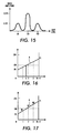
- the difference in the implementations can be seen in Figures 18 and 19.
- Figure 18 illustrates the high addressability relationship between adjacent pixels utilizing the first interpolation version of high addressability error diffusion method. More specifically, it is noted that the P1 value of the present pixel is utilized as the P0 value for the next pixel.
- Figure 19 illustrates the high addressability relationship between pixels utilizing the second interpolation version of the high addressability error diffusion method.
- One problem associated with the utilization of a typical error diffusion process or a hybrid high addressable error diffusion process in rendering an image on a document is the occurrence of periodically repeating patterns. These patterns occur most notably at the grey levels of 85, 128, and 170 when an 8 bit data word is utilized to represent the grey level of the image data. For example, when the grey level input is 128, the binarized image can alternate between a checkerboard pattern and a vertical line pattern. Depending on the printer spot size and the grey level at which the spot was mapped, the vertical line pattern can appear lighter than the checkered board pattern, thereby producing a undesired artifact.
- a system for processing image data having a multi-level grey signal having a first number of grey levels comprises means for receiving a multi-level grey scale pixel value representing a pixel having a first resolution; threshold means for generating a threshold value; reduction means for reducing the number of levels in the multi-level grey scale pixel value; error means for generating an error value as a result of the reduction process by said reduction means; diffusing means for diffusing the error value to multi-level grey scale pixel values of adjacent pixels; and perturbing means for perturbing the relationship between the threshold value and the multi-level grey signal according to an image classification of the multi-level grey scale pixel value, thereby effecting the output from said reduction means.
- a method of processing image data having a multi-level grey signal having a first number of grey levels comprises:
- Figure 3 illustrates one embodiment which perturbs a threshold relationship between a modified video image signal and a threshold signal by adding either a random noise to a hybrid high addressable error diffusion modified video, a threshold signal in the hybrid high addressable error diffusion binarization system, a video signal, or a error signal being used to modified the video signal.
- a circuit performs a screening/error diffusion process on an eight-bit image value.
- the error component (e FIFO + e FB ) utilized by adder 5 is received from error buffer 7 (e FIFO ) which stores the propagated error and binarization circuit 9 (e FB ).
- the further modified signal V S " is fed into binarization circuit 9 which converts the multi-level modified signal V S " to a binary output by utilizing an error diffusion/threshold process.
- Some of the error (e FB ) from this process is fed back directly to the next to be processed pixel, while the rest (e FIFO ) is stored in the error buffer 7 for processing of pixels in the next scanline.
- the apportionment of the error is based on weighting coefficients. Any set of coefficients can be used. In a preferred embodiment, the weighting coefficients are the coefficients described in U.S. Patent Number 5,353,127. The entire contents of U.S. Patent Number 5,353,127 are hereby incorporated by reference.
- the error that is produced represents the difference between the desired output, the multi-level image data value, and the actual output value which is either 255 or 0 if the multi-level of the image data is represented by 8 bits.
- This error is diffused, thereby retaining as much grey level information as possible.
- the combined screening and high addressability error diffusion rendering can be utilized using a simple vertical line screen pattern as illustrated in Figure 6.
- the process can be utilized with a 45° line screen as illustrated in Figure 7.
- the process can also be utilized with a dot screen or a constant screen.
- a dot screen is utilized in a continuous tone region and a constant screen is used in a text region to emulate a simple error diffusion process. This creates smoother transitions from window-to-window or from effect-to-effect since the error stored in the buffer will be within the same range for both continuous tone and text regions.
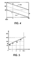
- the conversion from the pixel video signal V to the screen modulated signal V S ' is depicted in Figure 4.
- the screen modulated video signal V S has values varying between the levels A and B as the screen value S vary between 0 and 255.
- the value e i represents the rendering error propagated to the present i-th pixel from the previous pixels.
- Figure 3 illustrates a noise circuit 10 which generates noise to be either fed to the adder 5 so as to modified the video signal or fed to a threshold circuit, which generates the threshold value for the binarization process carried out by binarization circuit 9, so as to modify the threshold value.
- a noise generator circuit 10 which generates noise to be either fed to the adder 5 so as to modified the video signal or fed to a threshold circuit, which generates the threshold value for the binarization process carried out by binarization circuit 9, so as to modify the threshold value.
- FIG 9 illustrates a random noise generator as utilized in the preferred embodiment.
- the random noise generator circuit 10 includes a random noise generator 11 which produces a random noise signal which is fed to a multiplier 15.
- the random number generated by the random noise generator 11 is uniformly distributed between plus or minus 255 with a period of over 14 million.
- the noise generator circuit 10 also includes a noise look-up table 13 which outputs a coefficient corresponding to the grey level information received by the look-up table.
- the look-up table 13 programs or tailors the amplitude of the random noise added to the threshold or image signal as a function of the input grey level.
- the noise look-up table 13 holds N-bit fraction numbers, coefficients, (as a function of input grey levels) which are multiplied with the random noise (number) generated by the random noise generator 11 and later added to either the threshold or image signal value. Any noise profile can be loaded into the look-up table to selectively vary the location and magnitude of the threshold permutation in order to disrupt the periodicity of any objectionable pattern.
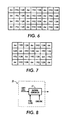
- FIG 15 A pattern or relationship is illustrated in Figure 15.
- the graph shows the relationship between the noise coefficients and the grey level values.
- the noise amplitude coefficient at grey level value 128 is 0.375 and the noise amplitude coefficients at grey level values 64 and 192 are 0.125. These values can be adjusted to reflect the particular properties of the printing device.
- the pattern is not limited to a three peak pattern. The pattern may have a multitude of peaks.
- the coefficient from the look-up table 13 is fed to the multiplier 15 which multiplies the coefficient and the noise signal generated by the random noise generator 11.
- the product of this multiplication is the actual random noise signal fed to the adder 5 or threshold circuit 12 of Figure 3.
- Figure 8 illustrates another embodiment which perturbs a threshold relationship between a modified video image signal and a threshold signal by adding a predetermined pattern to an error diffusion modified video signal.
- the pattern injected into the error diffusion modified video signal is either a checkerboard pattern as shown in Tables 1 and 2 below or a vertical line pattern as shown in Tables 3 and 4 below.
- a pattern generator 17 produces one of the patterns described above which is used in Figure 3 in lieu of the noise generator by noise generator circuit 10.
- the pattern generator circuit 10 of Figure 8 replaces the noise generator circuit 10 of Figure 3.
- the pattern is stored in a look-up table wherein the exact pattern values are determined by the grey level value of the error diffusion modified video signal, a pixel clock signal, and a linesync signal. This way the proper pattern value is matched with the correct pixel of the incoming video signal.
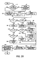
- Figures 20 and 21 illustrate the general conceptual method utilized by the present invention to perturb the threshold relationship at certain grey levels.
- Figure 20 illustrates the perturbing of the threshold/signal relationship when utilizing the first interpolation method described above for a hybrid high addressability error diffusion process.
- Step S1 it is determined whether the grey level of the image to be threshold is equal to 1/4, 1/3, or 1/2. If the image data is equal to one of these grey levels, the threshold/signal relationship is perturbed at Step S2. After the threshold signal relationship has been perturbed at Step S2 or if the image data has a grey level not equal to 1/4, 1/3, or 1/2, the pixel of video data is divided into N subpixels at step S10.
- Step S20 the values P0 i and P1 i are calculated as described above.
- Step S30 the X-coordinate of the point of intersection is determined and normalized by multiplying the difference between 128 and P0 by the value N and dividing this product by the difference of P1 and P0.
- Step S40 the normalized value X is compared with the value 0. If X is less than or equal to 0, Step S50 compares the value P1 with the value 128. If the value P1 is greater than or equal to 128, all the subpixels are set to an ON state at Step S60. However, if P1 is less than 128, Step S70 sets all the subpixels to an OFF state.
- Step S90 determines the integer value of X and sets this integer value equal to Y.
- the integer value Y is compared with the values 0 and N. If the value Y lies between 0 and N, Step S110 determines whether the value P1 is less than or equal to 128. If the value P1 is less than 128, Step S120 sets the subpixels 0 to Y to the ON state and the subpixels Y+1 to N to the OFF state. However, if Step S110 determines that the value P1 is greater than or equal to 128, Step S130 sets the subpixels 0 to Y to the OFF state and the subpixels Y+1 to N to the ON state.
- Step S100 determines that the value Y is not between the values 0 and N
- Steps S140 determines whether the value P1 is greater than or equal to 128. If the value P1 is greater than or equal to 128, Step S160 sets all subpixels to the ON state. However, if Step S140 determines that the value P1 is less than 128, Step S150 sets all the subpixels to the OFF state.
- Step S170 the number of ON subpixels is calculated and set equal to Z.
- Step S180 the error to be propagated to the downstream pixels is calculated. Namely, the error is calculated to represent the original low spatial resolution.
- Step S190 multiplies the error by weighting coefficients and distributes the weighted error terms to downstream pixels.
- Figure 21 illustrates the perturbing of the threshold/signal relationship when utilizing the second interpolation method described above for a hybrid high addressability error diffusion process.
- Step S1 it is determined whether the grey level of the image to be threshold is equal to 1/4, 1/3, or 1/2. If the image data is equal to one of these grey levels, the threshold/signal relationship is perturbed at Step S2. After the threshold signal relationship has been perturbed at Step S2 or if the image data has a grey level not equal to 1/4, 1/3, or 1/2, the pixel of video data is divided into N subpixels at step S10.
- Step S200 the P0 and P1 values are computed as noted above.
- the values Y and Z are set equal 0, wherein Y denotes the number of subpixels which are to be turned ON and Z denotes the addressability factor.
- Z is compared with N to determined whether all the subpixels within the modified video signal have been thresholded. If it is determined that subpixels remain to be thresholded, the process moves to Step S230 wherein the next subpixel value is computed. Step S240 then compares the computed subpixel value with the threshold value, namely 128.
- Step S260 sets the subpixel value to the ON state, and Step S270 increments the value Y indicating the number of subpixels that are set ON. However, if the subpixel value is less than 128, Step S250 sets the subpixel value to OFF.
- Step S280 Upon the completion of either Step S250 or Step 270, the process proceeds to Step S280 wherein the high addressability value Z is incremented. This subroutine is repeated until all subpixel values within the modified video signal are compared with the threshold value. Upon completing the comparison of all subpixel values, the process advances to Step S290 wherein the number of ON subpixels are calculated.
- Step S300 the error from the threshold process is calculated so that the value represents the original lower spatial resolution.
- Step S310 multiplies the error by weighting coefficients and distributes the error to downstream pixels.
- Step S1 can be modified from a three value decision state to a state making a determination as to what is the actual the grey level value of the image signal.
- Step S2 the branch from Step S1 directly to Step S10 is eliminated, and Steps S2, S21, S22, S23, and S24 perturb the threshold/signal relationship for every pixel with a different value.
- the threshold/signal relationship is perturbed over the entire image wherein each possible grey level has assigned thereto an individual perturbing pattern value as in Figure 8 or an individual coefficient value as in Figure 9.
- the possible periodic patterns for equal numbers of white and black pixels are checkerboard, vertical lines, or horizontal lines.
- the images are left to settle into one of these stages, depending of the weighting coefficients and the boundary conditions of the image processing operation. From a symmetric point of view, however, if the threshold in the error diffusion process is perturbed in a particular manner, the output from the thresholding process would be able to lock into a particular binary output having a certain state. This locking in result would effect the final appearance of the image by reducing the pattern shifting artifacts discussed above.
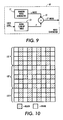
- Figure 10 illustrates a pattern shifting artifact occurring at a grey level corresponding to 1/2 or 128 when the image signal is represented by an eight bit byte. It is noted that in the section corresponding to 121, the pattern is one of vertical lines, whereas the pattern in section 122 is a checkerboard pattern. Moreover, as the image proceeds to section 123, the pattern shifts back to a vertical line pattern. It is this pattern shifting in the midtone region (a region having a grey value of 128 out of a possible 255) that creates the pattern shifting artifact that can be distracting to the actual appearance of the image.
- the midtone region a region having a grey value of 128 out of a possible 255
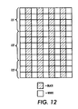
- the shaded squares in Figure 10 represent black pixels in the image to be reproduced and the non-shaded squares in Figure 10 represent white pixels in the image to be reproduced. This convention is also used in Figures 11, 12, 13, and 14. If the present invention is utilized in a color apparatus, the shaded squares in Figure 12 would represent to be printed pixels for a particular color space (toner or ink) and the non-shaded squares in Figure 12 would represent not to be printed pixels for a particular color space (toner or ink).
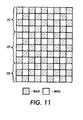
- Figure 11 illustrates the same midtone region (1/2 or 128 grey level) as illustrated in Figure 10 without the pattern shifting artifact. More specifically, the image illustrated in Figure 11 is rendered utilizing a constant threshold at 128 which is modulated with an amplitude of 20 in a checkerboard pattern or scheme. More specifically, the actual threshold value generated for utilization by a binarization circuit would be represented by the pattern illustrated in Table 1 below. 108 148 108 148 148 108 148 108 148 108 148 148 108 148 108 108 108 108 108 148 108 108 108 108 108 108 148 108 108 108 108 108 108 108 108 108 108 108 108 108 108 108 108 108 108 108 108 108 108 108 108 108 108 108 108 108 108 108 108 108 108 108 108 108 108 108 108 108 108 108 108 108 108 108 108 108 108
- Table 2 shows the value pattern added to the image signal to implement the checkerboard pattern when the system modifies the image signal.
- Figure 12 illustrates the same midtone region (1/2 or 128 grey level) as illustrated in Figure 10 without the pattern shifting artifact. More specifically, the image illustrated in Figure 12 is rendered utilizing a constant threshold at 128 which is modulated with an amplitude of 20 in a vertical line pattern or scheme.
- the actual threshold value generated for utilization by a binarization circuit would be represented by the pattern illustrated in Table 3 below.
- Table 4 shows the value pattern added to the image signal to implement the vertical line pattern when the system modifies the image signal.
- a row represents a fast scan direction or electronic scanning direction
- a column represents a slow scan direction or mechanical scanning direction
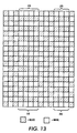
- Figure 13 illustrates a pixel representation of another pattern shifting artifact in a midtone region (a grey level corresponding to 128 or 1/2 for an eight bit image data byte).
- section 170 represents an area where a predominant horizontal line pattern is found.
- section 270 also represents an area having a predominant horizontal line pattern.
- the pattern shifts from a horizontal line pattern in section 170 to a checkerboard pattern then back to a horizontal line pattern in 270 as one travels in a fast scan direction.
- This pattern shifting artifact is substantially reduced in Figure 14.
- the midtone region (128 or 1/2 grey level) is rendered by perturbing the threshold/signal relationship with the inclusion of random noise.
- the horizontal line patterns are restricted to the areas where sections 171 and 172 overlap section 170 or the areas which correspond to the overlapping of section 270 with sections 271, 272, and 273.
- the addition of random noise for a particular grey level enables the image to be rendered with a substantial reduction in the pattern shifting artifact.
- Preprocessing operations include tonal reproduction curve (TRC) input mapping, gain and offset adjustment, spot overlap compensation, etc. These preprocessing operations all tend to shift objectionable periodic patterns to input grey level location other than what has been conventionally expected.
- TRC tonal reproduction curve
- the noise look-up table can be uniquely programmed and optimized to render images with good quality corresponding to any of the situations described above. More specifically, if the image is preprocessed utilizing a TRC input mapping and gain and offset adjustment, the artifact of pattern shifting can be centered at an input grey level of around 220. Thus, knowing that the pattern shifting artifact has been centered at a different input grey level, the noise look-up table can be programmed to inject random noise into the threshold/video signal relationship when the image signal is at a grey level around the new pattern shifting grey level. Thus, the programmability of the noise look-up table allows the present invention to be readily adaptable to any printing situation.
- one problem associated with error diffusion is the occurrence of periodically repeating patterns.
- perturbing of the error diffusion threshold level only at certain grey levels which were identified as producing potential objectionable patterns is used.
- merely perturbing the error diffusion threshold level based on the grey level of the video signal does not always remove the objectionable patterns.
- the conventional perturbation systems are static and thus preventing the system from dynamically perturbing the error diffusion threshold level when needed.
- a dynamic noise profile perturbing can remove objectionable patterns anywhere within an image by controlling the application of the perturbation based a number of factors. More specifically, the perturbing of the error diffusion threshold level can utilize several noise profiles and be dynamically selected on a per pixel basis based upon window effect pointers or image classification from an auto segmentation routine in addition to a certain grey level. This dynamic aspect of the perturbing of the error diffusion threshold level allows each predefined windowed region to have different noise profile requirements.
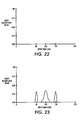
- Figures 22-24 show various noise profiles that can be utilized in a dynamic perturbation system according to the concepts of the present invention. For example, Figure 22 illustrates a noise profile wherein the error diffusion threshold level is not perturbed at any grey level or any window effect pointer.
- Figure 23 illustrates a noise profile which may be selected based on the grey level of the video signal and the window effect pointer associated with the pixel being processed.
- Figure 24 illustrates a modification of the noise profile of Figure 23 wherein the noise has been overamplified.
- the objectionable patterns may not always be at the same location relative to the input grey level when the image is being processed utilizing a specific TRC, a specific number of high-addressable bits, or a spot-overlap look-up table specifically tuned for a certain appearance. In such a situation, an objectionable binary output level may be shifted to another input grey level.
- the selection of the noise profile is based upon not only the grey level of the video signal being received but also upon the window effect pointer or other image classification information which is utilized to process the video signal.
- a window effect pointer is a dataword which contains information about the image classification of the associated pixel so that the proper image processing operations are performed on the pixel. This information can be developed by any conventional image segmentation or auto-segmentation routine.
- An example of a process which produces window effect pointers, image classification information, is described in US Patent Number 5,513,282. The entire contents of US Patent Number 5,513,282 are hereby incorporated by reference.
- Figure 25 illustrates a noise profile which is centered around the input grey level 228 for processing images utilizing a specific TRC, a specific number of high-addressable bits, and a spot overlap look-up table specifically tuned for a predetermined appearance.
- This noise profile would be selected based upon the window effect pointer of the pixel and grey level of the pixel, or the just window effect pointer if noise profile is generated from a programmable look-up table that is programmable from the pixel's grey level.
- Figure 26 illustrates a block diagram of a noise profile circuit according to the concepts of the present invention.
- registers 401 and 403 contain constant noise profiles associated with error diffusion and hybrid error diffusion, respectively.
- Figure 26 also shows a programmable noise look-up table 402 wherein the noise profile outputted by the look-up table 402 is dependent upon the input grey level of the video signal.
- Registers 401 and 403 and look-up table 402 are fed to a multiplexer 406 which selects which noise profile that will be utilized to perturb the error diffusion threshold level based on decoding information from decoding circuit 405.
- the decoding circuit 405 produces a signal to select the proper noise profile based upon the window effect bits associated with the pixel being processed and a noise option signal which indicates whether the noise option should be utilized or suppressed.
- the noise profile from multiplexer 406 is fed to multiplier 407 wherein the noise profile is multiplied with a signal generated from noise generator 404 to produce a noise signal that will be utilized to perturb the error diffusion threshold level.
- This noise signal is fed to adder 408 wherein the noise signal is added to the threshold value so as to perturb the relationship between the threshold and the incoming video signal.
- Figure 26 illustrates the adding of the noise to the threshold signal, this noise can also be added directly to the video signal, the error signal, or the video signal after it has been modified by the diffused error signal. In either situation, the noise is perturbing the relationship between the video signal and the threshold signal.
- the circuit of Figure 26 can be further extended to provide a generic architecture that will allow several noise profile look-up tables to be accessible and selected based upon the window effects pointers.
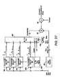
- An example of this extension is illustrated in Figure 27.
- a plurality of programmable noise look-up tables 4021, 4022, 4023,...402N are connected to a multiplexer 4060.
- Multiplexer 4060 is also connected to the register 4030 which has a constant noise and an input 0 which would be selected when the noise option is to be suppressed.
- a decoding circuit 4050 determines which programmable noise profile is outputted by the multiplexer 4060 based upon the window effect pointer bits; i.e., the image classification of the pixel being processed.
- the noise multiplier from multiplexer 4060 is fed to multiplier 407 to be multiplied with the noise generated by noise generator 404.
- the location of the objectionable textures or artifacts may change whenever the spot-overlap look-up table is modified and/or the amount of screen modulation is varied. This may be especially important in an auto-windowing environment where each window region may have a specific and different texture to perturb based upon the classification and characteristics of that object; i.e., determined from the object's histogram and overall window segmentation statistics.
- each object can be processed with a unique noise profile that can be dynamically assessed and selected based upon the window effects pointers.
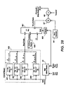
- Figure 28 illustrates another architecture which utilizes external memory to store each noise profile since only one noise value is required for every pixel.
- the various programmable noise look-up tables of Figure 27 are stored in a external memory 4020 which outputs the desired noise profile to multiplexer 4061.
- the window effect pointer and grey level video value are used to decode and access the external random access memory bank through random access memory address decoder circuit 501.
- the window effects pointer is also used by decoding circuit 4050 to determine which value the multiplexer 4061 will output as the multiplier to multiplier 407.
- the number of noise profiles utilized in this example can be easily expanded simply adding more memory to the external memory 4020.
Landscapes
- Engineering & Computer Science (AREA)
- Multimedia (AREA)
- Signal Processing (AREA)
- Image Processing (AREA)
- Facsimile Image Signal Circuits (AREA)
Applications Claiming Priority (2)
| Application Number | Priority Date | Filing Date | Title |
|---|---|---|---|
| US5975897P | 1997-09-23 | 1997-09-23 | |
| US59758P | 1997-09-23 |
Publications (3)
| Publication Number | Publication Date |
|---|---|
| EP0903932A2 true EP0903932A2 (de) | 1999-03-24 |
| EP0903932A3 EP0903932A3 (de) | 2000-04-05 |
| EP0903932B1 EP0903932B1 (de) | 2007-04-04 |
Family
ID=22025025
Family Applications (1)
| Application Number | Title | Priority Date | Filing Date |
|---|---|---|---|
| EP98307044A Expired - Lifetime EP0903932B1 (de) | 1997-09-23 | 1998-09-02 | System und Verfahren zur dynamischen Auswahl vom Rauschprofil für die Bildverarbeitung mittels hybrider Fehlerdiffusion |
Country Status (4)
| Country | Link |
|---|---|
| US (1) | US6449061B2 (de) |
| EP (1) | EP0903932B1 (de) |
| JP (1) | JP4121631B2 (de) |
| DE (1) | DE69837462T2 (de) |
Cited By (2)
| Publication number | Priority date | Publication date | Assignee | Title |
|---|---|---|---|---|
| EP1133162A3 (de) * | 2000-03-07 | 2003-02-26 | Seiko Instruments Inc. | Verfahren und Vorrichtung für Wiedergabe der Gradation von Bildern mit kontinuierlichen Tönen |
| EP1331804A3 (de) * | 2002-01-24 | 2003-11-19 | Ricoh Company, Ltd. | Bilderzeugungsvorrichtung und -verfahren, Computerprogramm und Aufzeichnungsmedium |
Families Citing this family (22)
| Publication number | Priority date | Publication date | Assignee | Title |
|---|---|---|---|---|
| JP3921678B2 (ja) * | 1998-02-24 | 2007-05-30 | ソニー株式会社 | 画像処理方法および装置 |
| KR20010071689A (ko) * | 1998-07-01 | 2001-07-31 | 벤자민 에프 커틀러 | 화소값을 변경하기 위한 이미지 프로세싱 회로 및 방법 |
| JP2000287086A (ja) * | 1999-03-31 | 2000-10-13 | Minolta Co Ltd | 画像処理装置 |
| JP3999406B2 (ja) * | 1999-05-18 | 2007-10-31 | インターナショナル・ビジネス・マシーンズ・コーポレーション | 拡散率の適応化を用いた誤差拡散方法及び装置 |
| US6671068B1 (en) * | 1999-09-30 | 2003-12-30 | Sharp Laboratories Of America, Inc. | Adaptive error diffusion with improved edge and sharpness perception |
| US6956673B2 (en) * | 2000-03-02 | 2005-10-18 | Minolta Co., Ltd. | Image processing apparatus and method to reduce gray levels of image |
| JP3583048B2 (ja) * | 2000-03-10 | 2004-10-27 | 富士通株式会社 | 画像処理方法、その装置及びその記憶媒体 |
| JP2003092689A (ja) * | 2001-09-18 | 2003-03-28 | Brother Ind Ltd | 画像形成装置及び画像形成プログラム |
| JP2003338928A (ja) * | 2002-05-21 | 2003-11-28 | Nec Corp | 画像信号の誤差拡散処理回路 |
| JP2005252695A (ja) * | 2004-03-04 | 2005-09-15 | Sony Corp | 誤差拡散処理方法、画像信号処理装置、印刷装置、プログラム及びデータテーブル構造 |
| US7369276B2 (en) * | 2004-03-05 | 2008-05-06 | Eastman Kodak Company | Multi-level halftoning providing improved texture uniformity |
| US8022909B2 (en) * | 2004-12-08 | 2011-09-20 | Via Technologies, Inc. | System, method, and apparatus for generating grayscales in an LCD panel |
| EP1758071A1 (de) * | 2005-08-22 | 2007-02-28 | Deutsche Thomson-Brandt Gmbh | Verfahren und Vorrichtung zur Videodatenbearbeitung für ein Anzeigegerät |
| US7697074B2 (en) * | 2006-02-08 | 2010-04-13 | Broadcom Corporation | System and method for video processing demonstration |
| CN100393099C (zh) * | 2006-08-31 | 2008-06-04 | 北京北大方正电子有限公司 | 调频调幅混合网点层次连续调控制方法 |
| US8314959B2 (en) * | 2007-07-03 | 2012-11-20 | Xerox Corporation | Adaptive cycle up convergence criteria |
| US8824013B2 (en) * | 2007-09-03 | 2014-09-02 | Sicpa Holding Sa | Error diffusion halftoning method for dark ink and light ink channels, based on a measure of solvent quantity that should be ejected for each pixel, and apparatus that performs the halftoning method |
| US7869095B2 (en) * | 2007-11-01 | 2011-01-11 | Xerox Corporation | System and method to perturb error diffusion patterns |
| US8018623B2 (en) * | 2008-02-29 | 2011-09-13 | Eastman Kodak Company | Multi-level halftoning providing reduced error diffusion artifacts |
| WO2010064309A1 (ja) * | 2008-12-03 | 2010-06-10 | 富士通株式会社 | 表示装置及び表示制御プログラム |
| JP5035400B2 (ja) * | 2010-08-06 | 2012-09-26 | ブラザー工業株式会社 | 画像形成装置及び画像形成プログラム |
| JP5505355B2 (ja) * | 2011-03-31 | 2014-05-28 | ブラザー工業株式会社 | 画像処理装置およびプログラム |
Family Cites Families (9)
| Publication number | Priority date | Publication date | Assignee | Title |
|---|---|---|---|---|
| JPS5760772A (en) * | 1980-09-29 | 1982-04-12 | Tomokazu Kato | Picture processing device |
| US4654721A (en) * | 1985-04-12 | 1987-03-31 | International Business Machines Corporation | System for reproducing multi-level digital images on a bi-level printer of fixed dot size |
| US5121447A (en) * | 1989-04-27 | 1992-06-09 | Canon Kabushiki Kaisha | Apparatus for performing gradation processing on image data |
| US5608821A (en) * | 1994-08-03 | 1997-03-04 | Xerox Corporation | Method of high addressability error diffusion |
| US5528384A (en) | 1994-08-03 | 1996-06-18 | Xerox Corporation | System and method for implementing fast high addressability error diffusion process |
| US6427030B1 (en) | 1994-08-03 | 2002-07-30 | Xerox Corporation | Method and system for image conversion utilizing dynamic error diffusion |
| JPH08237483A (ja) | 1994-12-01 | 1996-09-13 | Xerox Corp | イメージデータを処理するためのシステム及び方法 |
| EP0781034B1 (de) | 1995-12-21 | 2004-03-24 | Canon Kabushiki Kaisha | Bildverarbeitungsgerät und -verfahren |
| US5809177A (en) * | 1996-06-06 | 1998-09-15 | Xerox Corporation | Hybrid error diffusion pattern shifting reduction using programmable threshold perturbation |
-
1998
- 1998-04-20 US US09/062,404 patent/US6449061B2/en not_active Expired - Lifetime
- 1998-09-02 EP EP98307044A patent/EP0903932B1/de not_active Expired - Lifetime
- 1998-09-02 DE DE69837462T patent/DE69837462T2/de not_active Expired - Lifetime
- 1998-09-16 JP JP26177998A patent/JP4121631B2/ja not_active Expired - Fee Related
Cited By (4)
| Publication number | Priority date | Publication date | Assignee | Title |
|---|---|---|---|---|
| EP1133162A3 (de) * | 2000-03-07 | 2003-02-26 | Seiko Instruments Inc. | Verfahren und Vorrichtung für Wiedergabe der Gradation von Bildern mit kontinuierlichen Tönen |
| US7034964B2 (en) | 2000-03-07 | 2006-04-25 | Seiko Instruments Inc. | Method and apparatus for gradation reproduction of continuous tone image |
| EP1331804A3 (de) * | 2002-01-24 | 2003-11-19 | Ricoh Company, Ltd. | Bilderzeugungsvorrichtung und -verfahren, Computerprogramm und Aufzeichnungsmedium |
| US7564588B2 (en) | 2002-01-24 | 2009-07-21 | Ricoh Company, Ltd. | Image forming device, image forming method, and recording medium that provide multi-level error diffusion |
Also Published As
| Publication number | Publication date |
|---|---|
| JP4121631B2 (ja) | 2008-07-23 |
| EP0903932B1 (de) | 2007-04-04 |
| JPH11164146A (ja) | 1999-06-18 |
| DE69837462D1 (de) | 2007-05-16 |
| US20010015816A1 (en) | 2001-08-23 |
| EP0903932A3 (de) | 2000-04-05 |
| US6449061B2 (en) | 2002-09-10 |
| DE69837462T2 (de) | 2007-12-20 |
Similar Documents
| Publication | Publication Date | Title |
|---|---|---|
| US5809177A (en) | Hybrid error diffusion pattern shifting reduction using programmable threshold perturbation | |
| EP0903932B1 (de) | System und Verfahren zur dynamischen Auswahl vom Rauschprofil für die Bildverarbeitung mittels hybrider Fehlerdiffusion | |
| US5880857A (en) | Error diffusion pattern shifting reduction through programmable threshold perturbation | |
| US6144775A (en) | Method and system for storing error values for an image conversion process utilizing dynamic error diffusion | |
| US5353127A (en) | Method for quantization gray level pixel data with extended distribution set | |
| US5805738A (en) | Image processing apparatus and method | |
| JPH10271331A (ja) | 画像処理方法及びその装置 | |
| US5822464A (en) | Method and system for processing image information using video dependent dampened screening and error diffusion | |
| US5805724A (en) | Method and system for hybrid error diffusion processing of image information using dynamic screens based on brightness/darkness settings | |
| US5787206A (en) | Method and system for processing image information using expanded dynamic screening and error diffusion | |
| US5577136A (en) | Image processing apparatus | |
| US6233360B1 (en) | Method and system for hybrid error diffusion processing of image information using adaptive white and black reference values | |
| EP0810773A2 (de) | Verfahren und System zur Bildverarbeitung durch hybride Fehlerdiffusion | |
| US20020097438A1 (en) | System and apparatus for single subpixel elimination with local error compensation in an high addressable error diffusion process | |
| US6369912B1 (en) | Image processing apparatus capable of applying line component to image | |
| JP4068181B2 (ja) | マルチレベル階調画素値のレベル数減少方法及びシステム | |
| US5754706A (en) | System and apparatus for single subpixel elimination in an high addressable error diffusion process | |
| US6061143A (en) | System and apparatus for single subpixel elimination with local error compensation in an high addressable error diffusion process | |
| EP0696131A2 (de) | Verfahren und Gerät zur Bildinformationsverarbeitung unter Verwendung von Rasterung und Fehlerdiffusion | |
| US8422080B2 (en) | Image processing apparatus and image processing method in which composite tone pixel data is provided based on tone pixel data generated by error diffusion processing and dither processing | |
| JPH0738767A (ja) | 画像2値化処理装置 | |
| JP2900907B2 (ja) | 画像処理装置 | |
| JPH07295527A (ja) | 画像信号2値化処理装置および方法 | |
| JPH10108009A (ja) | 画像処理方法及びその装置 | |
| JP2000050067A (ja) | 画像処理方法及びその装置 |
Legal Events
| Date | Code | Title | Description |
|---|---|---|---|
| PUAI | Public reference made under article 153(3) epc to a published international application that has entered the european phase |
Free format text: ORIGINAL CODE: 0009012 |
|
| AK | Designated contracting states |
Kind code of ref document: A2 Designated state(s): DE FR GB |
|
| AX | Request for extension of the european patent |
Free format text: AL;LT;LV;MK;RO;SI |
|
| PUAL | Search report despatched |
Free format text: ORIGINAL CODE: 0009013 |
|
| AK | Designated contracting states |
Kind code of ref document: A3 Designated state(s): AT BE CH CY DE DK ES FI FR GB GR IE IT LI LU MC NL PT SE |
|
| AX | Request for extension of the european patent |
Free format text: AL;LT;LV;MK;RO;SI |
|
| 17P | Request for examination filed |
Effective date: 20001005 |
|
| AKX | Designation fees paid |
Free format text: DE FR GB |
|
| GRAP | Despatch of communication of intention to grant a patent |
Free format text: ORIGINAL CODE: EPIDOSNIGR1 |
|
| GRAS | Grant fee paid |
Free format text: ORIGINAL CODE: EPIDOSNIGR3 |
|
| GRAA | (expected) grant |
Free format text: ORIGINAL CODE: 0009210 |
|
| AK | Designated contracting states |
Kind code of ref document: B1 Designated state(s): DE FR GB |
|
| REG | Reference to a national code |
Ref country code: GB Ref legal event code: FG4D |
|
| REF | Corresponds to: |
Ref document number: 69837462 Country of ref document: DE Date of ref document: 20070516 Kind code of ref document: P |
|
| ET | Fr: translation filed | ||
| PLBE | No opposition filed within time limit |
Free format text: ORIGINAL CODE: 0009261 |
|
| STAA | Information on the status of an ep patent application or granted ep patent |
Free format text: STATUS: NO OPPOSITION FILED WITHIN TIME LIMIT |
|
| 26N | No opposition filed |
Effective date: 20080107 |
|
| PGFP | Annual fee paid to national office [announced via postgrant information from national office to epo] |
Ref country code: DE Payment date: 20130820 Year of fee payment: 16 |
|
| PGFP | Annual fee paid to national office [announced via postgrant information from national office to epo] |
Ref country code: GB Payment date: 20130823 Year of fee payment: 16 |
|
| PGFP | Annual fee paid to national office [announced via postgrant information from national office to epo] |
Ref country code: FR Payment date: 20130920 Year of fee payment: 16 |
|
| REG | Reference to a national code |
Ref country code: DE Ref legal event code: R119 Ref document number: 69837462 Country of ref document: DE |
|
| GBPC | Gb: european patent ceased through non-payment of renewal fee |
Effective date: 20140902 |
|
| REG | Reference to a national code |
Ref country code: DE Ref legal event code: R119 Ref document number: 69837462 Country of ref document: DE Effective date: 20150401 |
|
| REG | Reference to a national code |
Ref country code: FR Ref legal event code: ST Effective date: 20150529 |
|
| PG25 | Lapsed in a contracting state [announced via postgrant information from national office to epo] |
Ref country code: GB Free format text: LAPSE BECAUSE OF NON-PAYMENT OF DUE FEES Effective date: 20140902 Ref country code: DE Free format text: LAPSE BECAUSE OF NON-PAYMENT OF DUE FEES Effective date: 20150401 |
|
| PG25 | Lapsed in a contracting state [announced via postgrant information from national office to epo] |
Ref country code: FR Free format text: LAPSE BECAUSE OF NON-PAYMENT OF DUE FEES Effective date: 20140930 |