EP1132499B1 - Alloy coating, method for forming the same, and member for high temperature apparatuses - Google Patents
Alloy coating, method for forming the same, and member for high temperature apparatuses Download PDFInfo
- Publication number
- EP1132499B1 EP1132499B1 EP01105658A EP01105658A EP1132499B1 EP 1132499 B1 EP1132499 B1 EP 1132499B1 EP 01105658 A EP01105658 A EP 01105658A EP 01105658 A EP01105658 A EP 01105658A EP 1132499 B1 EP1132499 B1 EP 1132499B1
- Authority
- EP
- European Patent Office
- Prior art keywords
- coating
- substrate
- alloy
- single crystal
- base single
- Prior art date
- Legal status (The legal status is an assumption and is not a legal conclusion. Google has not performed a legal analysis and makes no representation as to the accuracy of the status listed.)
- Expired - Lifetime
Links
- 238000000576 coating method Methods 0.000 title claims description 80
- 239000011248 coating agent Substances 0.000 title claims description 79
- 229910045601 alloy Inorganic materials 0.000 title claims description 48
- 239000000956 alloy Substances 0.000 title claims description 48
- 238000000034 method Methods 0.000 title description 7
- 239000000758 substrate Substances 0.000 claims description 66
- 239000012720 thermal barrier coating Substances 0.000 claims description 40
- 230000007797 corrosion Effects 0.000 claims description 30
- 238000005260 corrosion Methods 0.000 claims description 30
- 238000007747 plating Methods 0.000 claims description 25
- 150000003839 salts Chemical class 0.000 claims description 24
- 229910052804 chromium Inorganic materials 0.000 claims description 11
- 229910052721 tungsten Inorganic materials 0.000 claims description 10
- 229910052759 nickel Inorganic materials 0.000 claims description 9
- 238000005275 alloying Methods 0.000 claims description 5
- 229910000601 superalloy Inorganic materials 0.000 description 68
- 239000013078 crystal Substances 0.000 description 61
- 239000010410 layer Substances 0.000 description 34
- 229910000838 Al alloy Inorganic materials 0.000 description 29
- 238000009792 diffusion process Methods 0.000 description 20
- 230000003647 oxidation Effects 0.000 description 19
- 238000007254 oxidation reaction Methods 0.000 description 19
- 238000004544 sputter deposition Methods 0.000 description 18
- 229910052751 metal Inorganic materials 0.000 description 13
- 239000011651 chromium Substances 0.000 description 12
- PXHVJJICTQNCMI-UHFFFAOYSA-N Nickel Chemical compound [Ni] PXHVJJICTQNCMI-UHFFFAOYSA-N 0.000 description 11
- PNEYBMLMFCGWSK-UHFFFAOYSA-N aluminium oxide Inorganic materials [O-2].[O-2].[O-2].[Al+3].[Al+3] PNEYBMLMFCGWSK-UHFFFAOYSA-N 0.000 description 11
- 229910052593 corundum Inorganic materials 0.000 description 11
- 229910001845 yogo sapphire Inorganic materials 0.000 description 11
- 229910052782 aluminium Inorganic materials 0.000 description 10
- 230000015572 biosynthetic process Effects 0.000 description 10
- 229910052715 tantalum Inorganic materials 0.000 description 10
- VEXZGXHMUGYJMC-UHFFFAOYSA-M Chloride anion Chemical compound [Cl-] VEXZGXHMUGYJMC-UHFFFAOYSA-M 0.000 description 9
- KRHYYFGTRYWZRS-UHFFFAOYSA-M Fluoride anion Chemical compound [F-] KRHYYFGTRYWZRS-UHFFFAOYSA-M 0.000 description 9
- 239000002184 metal Substances 0.000 description 9
- 238000002474 experimental method Methods 0.000 description 8
- 239000010955 niobium Substances 0.000 description 8
- 229910003303 NiAl2O4 Inorganic materials 0.000 description 7
- 230000006866 deterioration Effects 0.000 description 6
- 239000007789 gas Substances 0.000 description 6
- 229910052741 iridium Inorganic materials 0.000 description 6
- 229910052750 molybdenum Inorganic materials 0.000 description 6
- 229910052758 niobium Inorganic materials 0.000 description 6
- 239000000919 ceramic Substances 0.000 description 5
- 239000000203 mixture Substances 0.000 description 5
- 150000004767 nitrides Chemical class 0.000 description 5
- BASFCYQUMIYNBI-UHFFFAOYSA-N platinum Substances [Pt] BASFCYQUMIYNBI-UHFFFAOYSA-N 0.000 description 5
- 239000011253 protective coating Substances 0.000 description 5
- 230000001681 protective effect Effects 0.000 description 5
- 229910052719 titanium Inorganic materials 0.000 description 5
- 239000010936 titanium Substances 0.000 description 5
- MCMNRKCIXSYSNV-UHFFFAOYSA-N Zirconium dioxide Chemical compound O=[Zr]=O MCMNRKCIXSYSNV-UHFFFAOYSA-N 0.000 description 4
- 230000004888 barrier function Effects 0.000 description 4
- 238000006243 chemical reaction Methods 0.000 description 4
- 230000007547 defect Effects 0.000 description 4
- 230000002950 deficient Effects 0.000 description 4
- QDOXWKRWXJOMAK-UHFFFAOYSA-N dichromium trioxide Chemical compound O=[Cr]O[Cr]=O QDOXWKRWXJOMAK-UHFFFAOYSA-N 0.000 description 4
- 230000002035 prolonged effect Effects 0.000 description 4
- 229910052702 rhenium Inorganic materials 0.000 description 4
- 238000005507 spraying Methods 0.000 description 4
- 229910003310 Ni-Al Inorganic materials 0.000 description 3
- 238000005524 ceramic coating Methods 0.000 description 3
- 239000000460 chlorine Substances 0.000 description 3
- 238000010586 diagram Methods 0.000 description 3
- 238000004070 electrodeposition Methods 0.000 description 3
- 239000011777 magnesium Substances 0.000 description 3
- 238000002844 melting Methods 0.000 description 3
- 239000007800 oxidant agent Substances 0.000 description 3
- 239000010948 rhodium Substances 0.000 description 3
- IJGRMHOSHXDMSA-UHFFFAOYSA-N Atomic nitrogen Chemical compound N#N IJGRMHOSHXDMSA-UHFFFAOYSA-N 0.000 description 2
- 229910000599 Cr alloy Inorganic materials 0.000 description 2
- XEEYBQQBJWHFJM-UHFFFAOYSA-N Iron Chemical compound [Fe] XEEYBQQBJWHFJM-UHFFFAOYSA-N 0.000 description 2
- 229910013618 LiCl—KCl Inorganic materials 0.000 description 2
- ZOKXTWBITQBERF-UHFFFAOYSA-N Molybdenum Chemical compound [Mo] ZOKXTWBITQBERF-UHFFFAOYSA-N 0.000 description 2
- 229910000905 alloy phase Inorganic materials 0.000 description 2
- VSCWAEJMTAWNJL-UHFFFAOYSA-K aluminium trichloride Chemical compound Cl[Al](Cl)Cl VSCWAEJMTAWNJL-UHFFFAOYSA-K 0.000 description 2
- 229910052801 chlorine Inorganic materials 0.000 description 2
- GKOZUEZYRPOHIO-UHFFFAOYSA-N iridium atom Chemical compound [Ir] GKOZUEZYRPOHIO-UHFFFAOYSA-N 0.000 description 2
- 229910052749 magnesium Inorganic materials 0.000 description 2
- 239000011733 molybdenum Substances 0.000 description 2
- GUCVJGMIXFAOAE-UHFFFAOYSA-N niobium atom Chemical compound [Nb] GUCVJGMIXFAOAE-UHFFFAOYSA-N 0.000 description 2
- 229910052697 platinum Inorganic materials 0.000 description 2
- 229910052703 rhodium Inorganic materials 0.000 description 2
- 229910052710 silicon Inorganic materials 0.000 description 2
- 229910052717 sulfur Inorganic materials 0.000 description 2
- 238000004381 surface treatment Methods 0.000 description 2
- GUVRBAGPIYLISA-UHFFFAOYSA-N tantalum atom Chemical compound [Ta] GUVRBAGPIYLISA-UHFFFAOYSA-N 0.000 description 2
- WFKWXMTUELFFGS-UHFFFAOYSA-N tungsten Chemical compound [W] WFKWXMTUELFFGS-UHFFFAOYSA-N 0.000 description 2
- 239000010937 tungsten Substances 0.000 description 2
- 229910018507 Al—Ni Inorganic materials 0.000 description 1
- KZBUYRJDOAKODT-UHFFFAOYSA-N Chlorine Chemical compound ClCl KZBUYRJDOAKODT-UHFFFAOYSA-N 0.000 description 1
- ZAMOUSCENKQFHK-UHFFFAOYSA-N Chlorine atom Chemical compound [Cl] ZAMOUSCENKQFHK-UHFFFAOYSA-N 0.000 description 1
- VYZAMTAEIAYCRO-UHFFFAOYSA-N Chromium Chemical compound [Cr] VYZAMTAEIAYCRO-UHFFFAOYSA-N 0.000 description 1
- FYYHWMGAXLPEAU-UHFFFAOYSA-N Magnesium Chemical compound [Mg] FYYHWMGAXLPEAU-UHFFFAOYSA-N 0.000 description 1
- 229910001182 Mo alloy Inorganic materials 0.000 description 1
- 229910021636 Rhenium(IV) chloride Inorganic materials 0.000 description 1
- XUIMIQQOPSSXEZ-UHFFFAOYSA-N Silicon Chemical compound [Si] XUIMIQQOPSSXEZ-UHFFFAOYSA-N 0.000 description 1
- NINIDFKCEFEMDL-UHFFFAOYSA-N Sulfur Chemical compound [S] NINIDFKCEFEMDL-UHFFFAOYSA-N 0.000 description 1
- XAGFODPZIPBFFR-UHFFFAOYSA-N aluminium Chemical compound [Al] XAGFODPZIPBFFR-UHFFFAOYSA-N 0.000 description 1
- 238000010420 art technique Methods 0.000 description 1
- QVGXLLKOCUKJST-UHFFFAOYSA-N atomic oxygen Chemical compound [O] QVGXLLKOCUKJST-UHFFFAOYSA-N 0.000 description 1
- 239000010953 base metal Substances 0.000 description 1
- 239000011247 coating layer Substances 0.000 description 1
- 239000010941 cobalt Substances 0.000 description 1
- 229910017052 cobalt Inorganic materials 0.000 description 1
- GUTLYIVDDKVIGB-UHFFFAOYSA-N cobalt atom Chemical compound [Co] GUTLYIVDDKVIGB-UHFFFAOYSA-N 0.000 description 1
- 150000001875 compounds Chemical class 0.000 description 1
- 238000005336 cracking Methods 0.000 description 1
- 230000005496 eutectics Effects 0.000 description 1
- 239000007792 gaseous phase Substances 0.000 description 1
- 230000005764 inhibitory process Effects 0.000 description 1
- 229910052742 iron Inorganic materials 0.000 description 1
- 150000002739 metals Chemical class 0.000 description 1
- 238000005121 nitriding Methods 0.000 description 1
- 229910052757 nitrogen Inorganic materials 0.000 description 1
- 239000001301 oxygen Substances 0.000 description 1
- 229910052760 oxygen Inorganic materials 0.000 description 1
- 230000035515 penetration Effects 0.000 description 1
- 238000005240 physical vapour deposition Methods 0.000 description 1
- 238000002360 preparation method Methods 0.000 description 1
- WUAPFZMCVAUBPE-UHFFFAOYSA-N rhenium atom Chemical compound [Re] WUAPFZMCVAUBPE-UHFFFAOYSA-N 0.000 description 1
- MHOVAHRLVXNVSD-UHFFFAOYSA-N rhodium atom Chemical compound [Rh] MHOVAHRLVXNVSD-UHFFFAOYSA-N 0.000 description 1
- 239000010703 silicon Substances 0.000 description 1
- 239000011593 sulfur Substances 0.000 description 1
Images

Classifications
-
- F—MECHANICAL ENGINEERING; LIGHTING; HEATING; WEAPONS; BLASTING
- F01—MACHINES OR ENGINES IN GENERAL; ENGINE PLANTS IN GENERAL; STEAM ENGINES
- F01D—NON-POSITIVE DISPLACEMENT MACHINES OR ENGINES, e.g. STEAM TURBINES
- F01D5/00—Blades; Blade-carrying members; Heating, heat-insulating, cooling or antivibration means on the blades or the members
- F01D5/12—Blades
- F01D5/28—Selecting particular materials; Particular measures relating thereto; Measures against erosion or corrosion
- F01D5/288—Protective coatings for blades
-
- C—CHEMISTRY; METALLURGY
- C23—COATING METALLIC MATERIAL; COATING MATERIAL WITH METALLIC MATERIAL; CHEMICAL SURFACE TREATMENT; DIFFUSION TREATMENT OF METALLIC MATERIAL; COATING BY VACUUM EVAPORATION, BY SPUTTERING, BY ION IMPLANTATION OR BY CHEMICAL VAPOUR DEPOSITION, IN GENERAL; INHIBITING CORROSION OF METALLIC MATERIAL OR INCRUSTATION IN GENERAL
- C23C—COATING METALLIC MATERIAL; COATING MATERIAL WITH METALLIC MATERIAL; SURFACE TREATMENT OF METALLIC MATERIAL BY DIFFUSION INTO THE SURFACE, BY CHEMICAL CONVERSION OR SUBSTITUTION; COATING BY VACUUM EVAPORATION, BY SPUTTERING, BY ION IMPLANTATION OR BY CHEMICAL VAPOUR DEPOSITION, IN GENERAL
- C23C28/00—Coating for obtaining at least two superposed coatings either by methods not provided for in a single one of groups C23C2/00 - C23C26/00 or by combinations of methods provided for in subclasses C23C and C25C or C25D
- C23C28/30—Coatings combining at least one metallic layer and at least one inorganic non-metallic layer
- C23C28/32—Coatings combining at least one metallic layer and at least one inorganic non-metallic layer including at least one pure metallic layer
- C23C28/321—Coatings combining at least one metallic layer and at least one inorganic non-metallic layer including at least one pure metallic layer with at least one metal alloy layer
-
- C—CHEMISTRY; METALLURGY
- C23—COATING METALLIC MATERIAL; COATING MATERIAL WITH METALLIC MATERIAL; CHEMICAL SURFACE TREATMENT; DIFFUSION TREATMENT OF METALLIC MATERIAL; COATING BY VACUUM EVAPORATION, BY SPUTTERING, BY ION IMPLANTATION OR BY CHEMICAL VAPOUR DEPOSITION, IN GENERAL; INHIBITING CORROSION OF METALLIC MATERIAL OR INCRUSTATION IN GENERAL
- C23C—COATING METALLIC MATERIAL; COATING MATERIAL WITH METALLIC MATERIAL; SURFACE TREATMENT OF METALLIC MATERIAL BY DIFFUSION INTO THE SURFACE, BY CHEMICAL CONVERSION OR SUBSTITUTION; COATING BY VACUUM EVAPORATION, BY SPUTTERING, BY ION IMPLANTATION OR BY CHEMICAL VAPOUR DEPOSITION, IN GENERAL
- C23C28/00—Coating for obtaining at least two superposed coatings either by methods not provided for in a single one of groups C23C2/00 - C23C26/00 or by combinations of methods provided for in subclasses C23C and C25C or C25D
- C23C28/30—Coatings combining at least one metallic layer and at least one inorganic non-metallic layer
- C23C28/32—Coatings combining at least one metallic layer and at least one inorganic non-metallic layer including at least one pure metallic layer
- C23C28/325—Coatings combining at least one metallic layer and at least one inorganic non-metallic layer including at least one pure metallic layer with layers graded in composition or in physical properties
-
- C—CHEMISTRY; METALLURGY
- C23—COATING METALLIC MATERIAL; COATING MATERIAL WITH METALLIC MATERIAL; CHEMICAL SURFACE TREATMENT; DIFFUSION TREATMENT OF METALLIC MATERIAL; COATING BY VACUUM EVAPORATION, BY SPUTTERING, BY ION IMPLANTATION OR BY CHEMICAL VAPOUR DEPOSITION, IN GENERAL; INHIBITING CORROSION OF METALLIC MATERIAL OR INCRUSTATION IN GENERAL
- C23C—COATING METALLIC MATERIAL; COATING MATERIAL WITH METALLIC MATERIAL; SURFACE TREATMENT OF METALLIC MATERIAL BY DIFFUSION INTO THE SURFACE, BY CHEMICAL CONVERSION OR SUBSTITUTION; COATING BY VACUUM EVAPORATION, BY SPUTTERING, BY ION IMPLANTATION OR BY CHEMICAL VAPOUR DEPOSITION, IN GENERAL
- C23C28/00—Coating for obtaining at least two superposed coatings either by methods not provided for in a single one of groups C23C2/00 - C23C26/00 or by combinations of methods provided for in subclasses C23C and C25C or C25D
- C23C28/30—Coatings combining at least one metallic layer and at least one inorganic non-metallic layer
- C23C28/34—Coatings combining at least one metallic layer and at least one inorganic non-metallic layer including at least one inorganic non-metallic material layer, e.g. metal carbide, nitride, boride, silicide layer and their mixtures, enamels, phosphates and sulphates
- C23C28/345—Coatings combining at least one metallic layer and at least one inorganic non-metallic layer including at least one inorganic non-metallic material layer, e.g. metal carbide, nitride, boride, silicide layer and their mixtures, enamels, phosphates and sulphates with at least one oxide layer
- C23C28/3455—Coatings combining at least one metallic layer and at least one inorganic non-metallic layer including at least one inorganic non-metallic material layer, e.g. metal carbide, nitride, boride, silicide layer and their mixtures, enamels, phosphates and sulphates with at least one oxide layer with a refractory ceramic layer, e.g. refractory metal oxide, ZrO2, rare earth oxides or a thermal barrier system comprising at least one refractory oxide layer
-
- C—CHEMISTRY; METALLURGY
- C23—COATING METALLIC MATERIAL; COATING MATERIAL WITH METALLIC MATERIAL; CHEMICAL SURFACE TREATMENT; DIFFUSION TREATMENT OF METALLIC MATERIAL; COATING BY VACUUM EVAPORATION, BY SPUTTERING, BY ION IMPLANTATION OR BY CHEMICAL VAPOUR DEPOSITION, IN GENERAL; INHIBITING CORROSION OF METALLIC MATERIAL OR INCRUSTATION IN GENERAL
- C23C—COATING METALLIC MATERIAL; COATING MATERIAL WITH METALLIC MATERIAL; SURFACE TREATMENT OF METALLIC MATERIAL BY DIFFUSION INTO THE SURFACE, BY CHEMICAL CONVERSION OR SUBSTITUTION; COATING BY VACUUM EVAPORATION, BY SPUTTERING, BY ION IMPLANTATION OR BY CHEMICAL VAPOUR DEPOSITION, IN GENERAL
- C23C30/00—Coating with metallic material characterised only by the composition of the metallic material, i.e. not characterised by the coating process
-
- C—CHEMISTRY; METALLURGY
- C25—ELECTROLYTIC OR ELECTROPHORETIC PROCESSES; APPARATUS THEREFOR
- C25D—PROCESSES FOR THE ELECTROLYTIC OR ELECTROPHORETIC PRODUCTION OF COATINGS; ELECTROFORMING; APPARATUS THEREFOR
- C25D3/00—Electroplating: Baths therefor
- C25D3/02—Electroplating: Baths therefor from solutions
- C25D3/54—Electroplating: Baths therefor from solutions of metals not provided for in groups C25D3/04 - C25D3/50
-
- C—CHEMISTRY; METALLURGY
- C25—ELECTROLYTIC OR ELECTROPHORETIC PROCESSES; APPARATUS THEREFOR
- C25D—PROCESSES FOR THE ELECTROLYTIC OR ELECTROPHORETIC PRODUCTION OF COATINGS; ELECTROFORMING; APPARATUS THEREFOR
- C25D3/00—Electroplating: Baths therefor
- C25D3/66—Electroplating: Baths therefor from melts
-
- F—MECHANICAL ENGINEERING; LIGHTING; HEATING; WEAPONS; BLASTING
- F05—INDEXING SCHEMES RELATING TO ENGINES OR PUMPS IN VARIOUS SUBCLASSES OF CLASSES F01-F04
- F05D—INDEXING SCHEME FOR ASPECTS RELATING TO NON-POSITIVE-DISPLACEMENT MACHINES OR ENGINES, GAS-TURBINES OR JET-PROPULSION PLANTS
- F05D2230/00—Manufacture
- F05D2230/90—Coating; Surface treatment
-
- F—MECHANICAL ENGINEERING; LIGHTING; HEATING; WEAPONS; BLASTING
- F05—INDEXING SCHEMES RELATING TO ENGINES OR PUMPS IN VARIOUS SUBCLASSES OF CLASSES F01-F04
- F05D—INDEXING SCHEME FOR ASPECTS RELATING TO NON-POSITIVE-DISPLACEMENT MACHINES OR ENGINES, GAS-TURBINES OR JET-PROPULSION PLANTS
- F05D2300/00—Materials; Properties thereof
- F05D2300/60—Properties or characteristics given to material by treatment or manufacturing
- F05D2300/611—Coating
-
- Y—GENERAL TAGGING OF NEW TECHNOLOGICAL DEVELOPMENTS; GENERAL TAGGING OF CROSS-SECTIONAL TECHNOLOGIES SPANNING OVER SEVERAL SECTIONS OF THE IPC; TECHNICAL SUBJECTS COVERED BY FORMER USPC CROSS-REFERENCE ART COLLECTIONS [XRACs] AND DIGESTS
- Y02—TECHNOLOGIES OR APPLICATIONS FOR MITIGATION OR ADAPTATION AGAINST CLIMATE CHANGE
- Y02T—CLIMATE CHANGE MITIGATION TECHNOLOGIES RELATED TO TRANSPORTATION
- Y02T50/00—Aeronautics or air transport
- Y02T50/60—Efficient propulsion technologies, e.g. for aircraft
-
- Y—GENERAL TAGGING OF NEW TECHNOLOGICAL DEVELOPMENTS; GENERAL TAGGING OF CROSS-SECTIONAL TECHNOLOGIES SPANNING OVER SEVERAL SECTIONS OF THE IPC; TECHNICAL SUBJECTS COVERED BY FORMER USPC CROSS-REFERENCE ART COLLECTIONS [XRACs] AND DIGESTS
- Y10—TECHNICAL SUBJECTS COVERED BY FORMER USPC
- Y10T—TECHNICAL SUBJECTS COVERED BY FORMER US CLASSIFICATION
- Y10T428/00—Stock material or miscellaneous articles
- Y10T428/12—All metal or with adjacent metals
- Y10T428/12493—Composite; i.e., plural, adjacent, spatially distinct metal components [e.g., layers, joint, etc.]
- Y10T428/12535—Composite; i.e., plural, adjacent, spatially distinct metal components [e.g., layers, joint, etc.] with additional, spatially distinct nonmetal component
- Y10T428/12583—Component contains compound of adjacent metal
- Y10T428/1259—Oxide
-
- Y—GENERAL TAGGING OF NEW TECHNOLOGICAL DEVELOPMENTS; GENERAL TAGGING OF CROSS-SECTIONAL TECHNOLOGIES SPANNING OVER SEVERAL SECTIONS OF THE IPC; TECHNICAL SUBJECTS COVERED BY FORMER USPC CROSS-REFERENCE ART COLLECTIONS [XRACs] AND DIGESTS
- Y10—TECHNICAL SUBJECTS COVERED BY FORMER USPC
- Y10T—TECHNICAL SUBJECTS COVERED BY FORMER US CLASSIFICATION
- Y10T428/00—Stock material or miscellaneous articles
- Y10T428/12—All metal or with adjacent metals
- Y10T428/12493—Composite; i.e., plural, adjacent, spatially distinct metal components [e.g., layers, joint, etc.]
- Y10T428/12771—Transition metal-base component
- Y10T428/12806—Refractory [Group IVB, VB, or VIB] metal-base component
- Y10T428/12812—Diverse refractory group metal-base components: alternative to or next to each other
-
- Y—GENERAL TAGGING OF NEW TECHNOLOGICAL DEVELOPMENTS; GENERAL TAGGING OF CROSS-SECTIONAL TECHNOLOGIES SPANNING OVER SEVERAL SECTIONS OF THE IPC; TECHNICAL SUBJECTS COVERED BY FORMER USPC CROSS-REFERENCE ART COLLECTIONS [XRACs] AND DIGESTS
- Y10—TECHNICAL SUBJECTS COVERED BY FORMER USPC
- Y10T—TECHNICAL SUBJECTS COVERED BY FORMER US CLASSIFICATION
- Y10T428/00—Stock material or miscellaneous articles
- Y10T428/12—All metal or with adjacent metals
- Y10T428/12493—Composite; i.e., plural, adjacent, spatially distinct metal components [e.g., layers, joint, etc.]
- Y10T428/12771—Transition metal-base component
- Y10T428/12861—Group VIII or IB metal-base component
- Y10T428/12875—Platinum group metal-base component
Definitions
- the present invention relates to an alloy coating for use as a surface coating which can prolong the service life of members for apparatuses for high temperature applications (hereinafter referred to as "members for high temperature apparatuses"), such as gas turbine blades, jet engines, and heat-transfer tubes for boilers, a method for forming the same, and a member for high temperature apparatuses.
- members for high temperature apparatuses such as gas turbine blades, jet engines, and heat-transfer tubes for boilers
- a coating is applied on the surface thereof to improve the heat resistance and the corrosion resistance of the members.
- a ceramic coating called “thermal barrier coating” (hereinafter referred to as "TBC"
- TBC thermal barrier coating
- Such a ceramic coating has the problem that the difference in coefficient of thermal expansion between the substrate metal and the ceramic is so large that, when a ceramic layer is directly formed on the surface of the substrate, the ceramic layer is likely to be separated from the interface of the ceramic layer and the substrate.
- an undercoat 50 formed of an alloy layer and a topcoat 52 formed of, for example, a ceramic such as ZrO 2 are laminated in that order on the surface of the substrate 10, to improve the adhesion of TBC 54 to the substrate 10.
- the undercoat 50 is reacted with the substrate 10 to form an Al-deficient layer 56 and a layer 58 of Al 2 O 3 + NiAl 2 O 4 having poor protective properties at the interface of the undercoat 50 and the substrate 10, thus resulting in deterioration of TBC 54.
- TBC 54 is porous, atmosphere gas enters the inside of TBC 54 and then internally oxidizes or internally nitrides the substrate 10 to form an internal corrosion layer containing an internal oxide 36 and an internal nitride 38 within the substrate 10. For this reason, the service life of the member for high temperature apparatuses is as short as several months.
- the protective coating cannot be stably maintained for a long period of time, resulting in a short service life of the apparatus.
- the prolongation of the service life of a member for high temperature apparatuses is only made by lowering the service temperature of the apparatus while sacrificing the performance of the apparatus.
- the TBC layer is deteriorated as a result of a reaction of TBC with the substrate during use of the members, and, in addition, the substrate is internally oxidized or internally nitrided by atmosphere gas which has penetrated into the inside of the coating.
- the spray coating of a high Ni-high Cr alloy, etc. for improving the corrosion resistance, when the apparatus is used under an environment containing Cl, S or the like, which is highly corrosive at high temperatures, the consumption rate of the element constituting the protective coating, such as Cr or Al, is so high that a stable protective coating cannot be maintained for a long period of time.
- EP 0 848 071 describes a Ni-base alloy containing Re, W, Al, Cr for high temperature apparatuses.
- an element for imparting corrosion resistance such as chromium (Cr), aluminum (Al), silicon (Si), magnesium (Mg), niobium (Nb), tantalum (
- the interposed coating is considered to function as an excellent diffusion barrier which can inhibit the deterioration of TBC, caused by a reaction of TBC with the substrate, and the internal corrosion of the substrate.
- the technique of plating in a molten salt has the advantages that 1 the thickness and composition of the coating can be easily controlled; 2 the coating can be effected with ease by using a simple apparatus; 3 a dense coating having no significant defect can be formed; 4 there is few limitations on the size and shape of a substrate to be coated; and 5 the cost is low.
- the present invention has been accomplished under the above circumstances.
- the alloy coating is formed by plating in a molten salt and comprises an alloy, said alloy comprising Re as a base member, and alloying elements Cr, Ni, W and Al for providing a corrosion resistance alloy with the base member.
- a deterioration in substrate caused by corrosion and damage can be reduced by virtue of the alloy coating, which can function as a better diffusion barrier, covering the surface of the substrate, whereby the service life of the member is prolonged.
- a thermal barrier coating may be formed on the surface of the alloy coating.
- a deterioration in thermal barrier coating, caused by the reaction of the thermal barrier coating with the substrate, and the penetration of atmosphere gas into the substrate can be prevented by virtue of the alloy coating, which can function as a better diffusion barrier, interposed between the substrate and the thermal barrier coating, whereby the service life of the member is prolonged.
- Re is used as a high-melting metal
- Al as a metallic element for imparting corrosion resistance
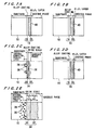
- FIGS. 1A and 1B show cross-sectional microstructures of Ni-base single crystal superalloys (Ni-Co-Cr-Al-W-Ta-Ti-Re-Mo alloy) having a coating, illustrative of different embodiments of the present invention, which can be used as a member for high temperature apparatuses. More specifically, FIG. 1A shows a coated Ni-base single crystal superalloy composed of a Ni-base single crystal superalloy (substrate) 10 and an alloy coating 16 covering the surface of the substrate 10, the alloy coating 16 being composed of a mixture of a Ni-Al alloy 12 with a Re-Al alloy 14.
- FIG. 1A shows a coated Ni-base single crystal superalloy composed of a Ni-base single crystal superalloy (substrate) 10 and an alloy coating 16 covering the surface of the substrate 10, the alloy coating 16 being composed of a mixture of a Ni-Al alloy 12 with a Re-Al alloy 14.
- FIG. 1A shows
- 1B shows a coated Ni-base single crystal superalloy composed of a substrate 10 and an alloy coating 16 covering the surface of the substrate 10, the alloy coating 16 being composed of a Re-Al alloy layer 18 and a Ni-Al alloy layer 20.
- Cr, W, and Ni diffused from the substrate 10 are contained in the Re-Al alloy layer, and an Al diffused layer 22 is formed at the interface between the substrate 10 and the alloy coating 16.
- the coated Ni-base single crystal superalloys having cross-sectional microstructures shown in FIGS. 1A and 1B were prepared by coating the surface of the Ni-base single crystal superalloy (substrate) 10 with a Re-Al alloy by plating in a molten salt. More specifically, in the preparation of the coated Ni-base single crystal superalloy shown in FIG.
- Al and Re were reacted with chlorine gas in an LiCl-KCl eutectic salt to produce AlCl 3 and ReCl 4 dissolved and absorbed directly in the LiCl-KCl molten salt, and this was used as the molten salt, and the surface of the substrate 10 was plated in the molten salt under the conditions of plating temperature 500°C, current 10 mA, and plating time 10 hr.
- the coated Ni-base single crystal superalloy shown in FIG. 1B was prepared by plating the substrate 10 in the same manner as described above in connection with FIG. 1A , except that the plating temperature was changed to 700°C.
- FIG. 1C shows a cross-sectional microstructure of a coated Ni-base single crystal superalloy illustrative of another embodiment of the present invention, wherein the surface of the substrate 10 has been coated with a Re-Al alloy coating 26 by sputtering.
- FIG. 1D shows a cross-sectional microstructure of a coated Ni-base single crystal superalloy, wherein the surface of the substrate 10 has been coated with a Re-Al alloy coating by sputtering, followed by Al vapor diffusion.
- the formation of a Re-Al alloy coating by sputtering followed by Al vapor diffusion results in the formation of a laminated structure of a Re-Al-(Cr-W-Ni) alloy layer 18 and a Ni-Al alloy layer 20, as with the structure shown in FIG. 1B . Further, the formation of an A1 diffused layer 22 is also observed at the substrate/coating interface. From FIGS. 1A to 1D , it is apparent that, when sputtering is solely adopted, the formed Re-Al alloy coating 26 have many cracks 26a (see FIG.
- FIGS. 2A to 2E show cross-sectional microstructures, after carrying out oxidation in air at 1150°C for 100 hr or in air at 1100°C for one month, of the coated Ni-base single crystal superalloys having the cross-sectional microstructrues shown in FIGS. 1A to 1D and a pure Ni-base single crystal superalloy not subjected to surface treatment (coating), wherein FIG. 2A corresponds to the coated superalloy shown in FIG. 1A , FIG. 2B the coated superalloy shown in FIG. 1B , FIG. 2C the coated superalloy shown in FIG. 1C , FIG. 2D the coated superalloy shown in FIG. 1D , and FIG. 2E the pure Ni-base single crystal superalloy having no coating.
- a thick oxide scale 34 composed of an inner layer 30 formed of Al 2 O 3 + Cr 2 O 3 and an outer layer 32 formed of NiAl 2 O 4 + NiO containing Ti and Ta was formed on the surface of the substrate 10 during the oxidation test. It is thus apparent that Cr, Ni, Ti, and Ta contained in the substrate 10 were outwardly diffused to form an oxide scale 34 having poor protective properties. Further, an internal corrosion product layer containing a discrete internal oxide 36 and an internal nitride 38 was formed within the substrate 10, indicating that oxygen and nitrogen in the gaseous phase were diffused into the substrate 10 to cause the internal oxidation and internal nitriding of the substrate 10.
- the Re-Al alloy coating 26 allows the metallic elements and gas to diffuse through the cracks 26a and thus allows the oxidation to proceed.
- an alloy coating illustrative of the present invention is to be formed by sputtering, reducing the thickness of the alloy coating, that is, the formation of a thin alloy coating, to reduce the creation of cracks will improve the heat resistance and the corrosion resistance.
- both sputtering and Al vapor diffusion were carried out to form the alloy coating ( FIG. 2D )
- sputtering followed by Al vapor diffusion results in the formation of a dense coating having no significant cracking to improve the corrosion resistance.
- Table 1 Increase in weight, mg ⁇ cm -2 (a) Not more than 2 (b) Not more than 2 (c) 10 to 20 (d) Not more than 2 (e) Not less than 40
- (a) corresponds to a change in weight of the coated Ni-base single crystal superalloy shown in FIG. 2A
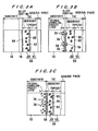
- FIG. 3A shows a cross-sectional microstructure of a coated Ni-base single crystal superalloy according to an embodiment of the present invention, after carrying out oxidation in air at 1150°C for 100 hr, or in air at 1100°C for one month.
- the coated sample was prepared by forming an alloy coating 16 on the surface of a Ni-base single crystal superalloy (substrate) 10 by electrodeposition in a molten salt and, on the surface of the alloy coating 16, TBC 54 compared of an undercoat 50 formed of an NiCoCrAlY alloy and a topcoat 52 formed of ZrO 2 .
- FIG. 3B shows a cross-sectional microstructure of a coated Ni-base single crystal superalloy illustrative of a further embodiment of the present invention, after carrying out oxidation in the same manner as described above in connection with FIG. 3A .
- the coated superalloy sample was prepared by sputtering a Re-Al alloy coating 26 on the surface of a Ni-base single crystal superalloy (substrate) 10 and forming, on the surface of the alloy coating 26, TBC 54 in the same manner as described above.
- FIG. 3C shows a cross-sectional microstructure, after oxidation in the same manner as described above, of a pure Ni-base single crystal superalloy (substrate) 10 on the surface of which TBC 54 has been directly formed.
- Table 2 Increase in weight, mg ⁇ cm -2 (a) Not more than 2 (b) 10 to 15 (c) Not less than 30
- (a) corresponds to a change in weight of the Ni-base single crystal superalloy shown in FIG. 3A
- the increase in weight was about one-fifteenth or less as compared with the Ni-base single crystal superalloy in which only TBC had been formed, indicating that the increase in weight due to oxidation was much smaller.
- Re is used as a high-melting metal
- Al is used as a metallic element for imparting corrosion resistance.
- the formation of an alloy coating composed Re-Cr-W-Al-Ni can improve the diffusion barrier function.
- the base metal is Re.
- Ni-base multi crystal superalloy may used instead of Ni-base single crystal superalloy.
- plating in a chloride-containing molten salt may be carried out in a fluoride-containing molten salt.
- an electrodeposition may be formed in a solution.
- plating may be carried out in a molten salt containing a first chloride or fluoride of Re and a second chloride or fluoride of at least one alloying element for imparting corrosion resistance, wherein an alloy of at least one metal contained in the first chloride or fluoride with at least one metal contained in the second chloride or fluoride is used as an electrode.
- a denser coating can be formed and, in addition, the composition of the coating can be easily controlled.
- plating may be carried out in a molten salt containing a first chloride or fluoride of Re and a second chloride or fluoride of at least one alloying element for imparting corrosion resistance, wherein at least one metal contained in the first chloride or fluoride and at least one metal contained in the second chloride or fluoride are used as electrodes for alternate or simultaneous plating.
- the composition and structure of the alloy coating can be controlled as desired.
- an alloy coating can be obtained which is stable at a high temperature of 1100°C or above, even at 1150°C or above, and possesses excellent oxidation resistance and, in addition, can inhibit the outward diffusion of metallic elements constituting the base (substrate) metal, such as Ni, Al, Ti, and Ta, and the inward diffusion of an oxidizing agent and the like. Further, the application of the alloy coating to members for high temperature apparatuses can provide highly heat-resistant and corrosion-resistant members with prolonged service life.
Landscapes
- Chemical & Material Sciences (AREA)
- Engineering & Computer Science (AREA)
- Materials Engineering (AREA)
- Metallurgy (AREA)
- Chemical Kinetics & Catalysis (AREA)
- Organic Chemistry (AREA)
- Mechanical Engineering (AREA)
- Inorganic Chemistry (AREA)
- Electrochemistry (AREA)
- Ceramic Engineering (AREA)
- General Engineering & Computer Science (AREA)
- Other Surface Treatments For Metallic Materials (AREA)
- Turbine Rotor Nozzle Sealing (AREA)
- Electroplating Methods And Accessories (AREA)
- Chemical Vapour Deposition (AREA)
Applications Claiming Priority (2)
| Application Number | Priority Date | Filing Date | Title |
|---|---|---|---|
| JP2000062613 | 2000-03-07 | ||
| JP2000062613 | 2000-03-07 |
Publications (3)
| Publication Number | Publication Date |
|---|---|
| EP1132499A2 EP1132499A2 (en) | 2001-09-12 |
| EP1132499A3 EP1132499A3 (en) | 2004-02-25 |
| EP1132499B1 true EP1132499B1 (en) | 2010-05-19 |
Family
ID=18582598
Family Applications (1)
| Application Number | Title | Priority Date | Filing Date |
|---|---|---|---|
| EP01105658A Expired - Lifetime EP1132499B1 (en) | 2000-03-07 | 2001-03-07 | Alloy coating, method for forming the same, and member for high temperature apparatuses |
Country Status (4)
| Country | Link |
|---|---|
| US (2) | US6830827B2 (enExample) |
| EP (1) | EP1132499B1 (enExample) |
| JP (1) | JP2001323332A (enExample) |
| DE (1) | DE60142138D1 (enExample) |
Families Citing this family (30)
| Publication number | Priority date | Publication date | Assignee | Title |
|---|---|---|---|---|
| JP5295474B2 (ja) * | 2000-09-28 | 2013-09-18 | 敏夫 成田 | ニオブ基合金耐熱部材 |
| JP4047115B2 (ja) | 2002-09-13 | 2008-02-13 | アルプス電気株式会社 | 軟磁性膜及びこの軟磁性膜を用いた薄膜磁気ヘッド、ならびに、前記軟磁性膜の製造方法 |
| US7466799B2 (en) * | 2003-04-09 | 2008-12-16 | Varian Medical Systems, Inc. | X-ray tube having an internal radiation shield |
| US6933052B2 (en) * | 2003-10-08 | 2005-08-23 | General Electric Company | Diffusion barrier and protective coating for turbine engine component and method for forming |
| EP1715081A1 (en) * | 2004-01-15 | 2006-10-25 | Ebara Corporation | Alloy coating for diffusion barrier, method for forming same, and high-temperature device member |
| US7778422B2 (en) * | 2004-02-27 | 2010-08-17 | Microsoft Corporation | Security associations for devices |
| US20060165547A1 (en) * | 2005-01-26 | 2006-07-27 | Honeywell International, Inc. | High strength rhenium alloys and high temperature components made from such alloys |
| DE102005011011A1 (de) * | 2005-03-10 | 2006-09-14 | Mtu Aero Engines Gmbh | Bauteil, insbesondere Gasturbinenbauteil |
| US8221901B2 (en) * | 2005-03-28 | 2012-07-17 | National Institute For Materials Science | Material for heat resistant component |
| US20070116890A1 (en) * | 2005-11-21 | 2007-05-24 | Honeywell International, Inc. | Method for coating turbine engine components with rhenium alloys using high velocity-low temperature spray process |
| JP4716328B2 (ja) * | 2006-07-05 | 2011-07-06 | 財団法人電力中央研究所 | 遮熱コーティングの寿命管理方法 |
| JP5146867B2 (ja) * | 2006-08-18 | 2013-02-20 | 独立行政法人物質・材料研究機構 | 高温耐久性に優れた耐熱部材 |
| EP2110449A4 (en) | 2006-09-13 | 2011-04-27 | Nat Inst For Materials Science | HEAT-RESISTANT ELEMENT |
| US8388890B2 (en) * | 2006-09-21 | 2013-03-05 | Tyco Electronics Corporation | Composition and method for applying an alloy having improved stress relaxation resistance |
| JP5182669B2 (ja) * | 2006-11-16 | 2013-04-17 | 国立大学法人北海道大学 | 多層合金皮膜、それを有する耐熱性金属部材および多層合金皮膜の製造方法 |
| JP4896702B2 (ja) * | 2006-12-22 | 2012-03-14 | 株式会社ディ・ビー・シー・システム研究所 | 合金皮膜、合金皮膜の製造方法および耐熱性金属部材 |
| CN101168815B (zh) * | 2007-12-05 | 2010-06-02 | 北京航空航天大学 | 片层铌钼硅基原位复合材料及其制备方法 |
| US8361178B2 (en) * | 2008-04-21 | 2013-01-29 | Smith International, Inc. | Tungsten rhenium compounds and composites and methods for forming the same |
| JP2012504192A (ja) * | 2008-09-29 | 2012-02-16 | ウイリアム・ディー.・ハースト | 合金被覆装置及びメタライディング方法 |
| US8367160B2 (en) * | 2010-11-05 | 2013-02-05 | United Technologies Corporation | Coating method for reactive metal |
| EP2697408B1 (en) | 2011-04-13 | 2018-09-12 | Rolls-Royce Corporation | Interfacial diffusion barrier layer including iridium on a metallic substrate |
| GB201109533D0 (en) * | 2011-06-08 | 2011-07-20 | Rolls Royce Plc | Temperature indicating paint |
| CN102650064A (zh) * | 2012-05-23 | 2012-08-29 | 深圳市新星轻合金材料股份有限公司 | 用于铝电解工业的钾冰晶石及其制备方法 |
| JP5936487B2 (ja) * | 2012-08-23 | 2016-06-22 | キヤノン株式会社 | アモルファス合金、成形用型および光学素子の製造方法 |
| EP2918705B1 (en) | 2014-03-12 | 2017-05-03 | Rolls-Royce Corporation | Coating including diffusion barrier layer including iridium and oxide layer and method of coating |
| CN106853436B (zh) * | 2016-12-29 | 2020-05-19 | 宁夏东方钽业股份有限公司 | 一种钼基复合涂层及其制备方法 |
| CN108914053B (zh) * | 2018-07-20 | 2020-04-28 | 中国人民解放军国防科技大学 | 铱涂层原位扩散改性制备超高温涂层的方法 |
| JP7661885B2 (ja) * | 2019-10-07 | 2025-04-15 | 株式会社レゾナック | 耐食性部材 |
| CN113281243A (zh) * | 2021-05-21 | 2021-08-20 | 北京航空航天大学 | 一种新型Co-Al-W基合金上梯度Al-Cr涂层腐蚀行为高通量表征方法 |
| CN114574834A (zh) * | 2021-12-02 | 2022-06-03 | 贵研铂业股份有限公司 | 一种Ta-Re层状复合材料及其制备方法和应用 |
Citations (1)
| Publication number | Priority date | Publication date | Assignee | Title |
|---|---|---|---|---|
| EP0848071A1 (en) * | 1996-12-11 | 1998-06-17 | United Technologies Corporation | Superalloy compositions |
Family Cites Families (22)
| Publication number | Priority date | Publication date | Assignee | Title |
|---|---|---|---|---|
| GB385859A (en) * | 1931-06-22 | 1933-01-05 | Siebert G M B H G | Improvements relating to catalytic reactions and catalysts for use therein |
| FR1385594A (fr) * | 1963-02-18 | 1965-01-15 | Union Carbide Corp | Dépôt électrolytique de métaux réfractaires |
| DE1771763A1 (enExample) * | 1967-07-03 | |||
| US4517253A (en) * | 1984-01-23 | 1985-05-14 | Rose Robert M | Cryoelectrodeposition |
| JPS6199925A (ja) * | 1984-10-19 | 1986-05-19 | Nec Corp | 磁気記憶体およびその製造方法 |
| JPS61144025A (ja) * | 1984-12-18 | 1986-07-01 | Matsushita Electric Ind Co Ltd | 半導体装置の製造方法 |
| US4731253A (en) * | 1987-05-04 | 1988-03-15 | Wall Colmonoy Corporation | Wear resistant coating and process |
| US5273712A (en) * | 1989-08-10 | 1993-12-28 | Siemens Aktiengesellschaft | Highly corrosion and/or oxidation-resistant protective coating containing rhenium |
| US5395221A (en) * | 1993-03-18 | 1995-03-07 | Praxair S.T. Technology, Inc. | Carbide or boride coated rotor for a positive displacement motor or pump |
| US5427866A (en) | 1994-03-28 | 1995-06-27 | General Electric Company | Platinum, rhodium, or palladium protective coatings in thermal barrier coating systems |
| US5556713A (en) | 1995-04-06 | 1996-09-17 | Southwest Research Institute | Diffusion barrier for protective coatings |
| GB9612811D0 (en) | 1996-06-19 | 1996-08-21 | Rolls Royce Plc | A thermal barrier coating for a superalloy article and a method of application thereof |
| EP0821076B1 (en) | 1996-07-23 | 2001-11-28 | ROLLS-ROYCE plc | A method of aluminising a superalloy |
| US5817371A (en) | 1996-12-23 | 1998-10-06 | General Electric Company | Thermal barrier coating system having an air plasma sprayed bond coat incorporating a metal diffusion, and method therefor |
| US6143141A (en) * | 1997-09-12 | 2000-11-07 | Southwest Research Institute | Method of forming a diffusion barrier for overlay coatings |
| JP3939362B2 (ja) * | 1997-10-30 | 2007-07-04 | アルストム | 高温保護コーティング |
| GB9724844D0 (en) * | 1997-11-26 | 1998-01-21 | Rolls Royce Plc | A coated superalloy article and a method of coating a superalloy article |
| JPH11350196A (ja) * | 1998-06-12 | 1999-12-21 | C Uyemura & Co Ltd | Bn複合ニッケル−タングステン合金皮膜及びその形成方法並びにピストンリング |
| US6168875B1 (en) * | 1998-10-02 | 2001-01-02 | Asea Brown Boveri Ag | Coatings for turbine components |
| US6004372A (en) * | 1999-01-28 | 1999-12-21 | Praxair S.T. Technology, Inc. | Thermal spray coating for gates and seats |
| US6306524B1 (en) | 1999-03-24 | 2001-10-23 | General Electric Company | Diffusion barrier layer |
| US6207297B1 (en) * | 1999-09-29 | 2001-03-27 | Siemens Westinghouse Power Corporation | Barrier layer for a MCrAlY basecoat superalloy combination |
-
2001
- 2001-03-06 US US09/799,036 patent/US6830827B2/en not_active Expired - Fee Related
- 2001-03-07 DE DE60142138T patent/DE60142138D1/de not_active Expired - Lifetime
- 2001-03-07 EP EP01105658A patent/EP1132499B1/en not_active Expired - Lifetime
- 2001-03-07 JP JP2001063686A patent/JP2001323332A/ja active Pending
-
2004
- 2004-05-06 US US10/839,161 patent/US6899926B2/en not_active Expired - Fee Related
Patent Citations (1)
| Publication number | Priority date | Publication date | Assignee | Title |
|---|---|---|---|---|
| EP0848071A1 (en) * | 1996-12-11 | 1998-06-17 | United Technologies Corporation | Superalloy compositions |
Also Published As
| Publication number | Publication date |
|---|---|
| US6830827B2 (en) | 2004-12-14 |
| EP1132499A2 (en) | 2001-09-12 |
| US20050079089A1 (en) | 2005-04-14 |
| EP1132499A3 (en) | 2004-02-25 |
| US6899926B2 (en) | 2005-05-31 |
| JP2001323332A (ja) | 2001-11-22 |
| DE60142138D1 (de) | 2010-07-01 |
| US20010026877A1 (en) | 2001-10-04 |
Similar Documents
| Publication | Publication Date | Title |
|---|---|---|
| EP1132499B1 (en) | Alloy coating, method for forming the same, and member for high temperature apparatuses | |
| EP1463846B1 (en) | Mcraly bond coating and method of depositing said mcraly bond coating | |
| US6528189B1 (en) | Article with a protective coating system including an improved anchoring layer and method of manufacturing the same | |
| US6255001B1 (en) | Bond coat for a thermal barrier coating system and method therefor | |
| EP0979881B1 (en) | Thermal barrier and overlay coating systems comprising composite metal/metal oxide bond coating layers | |
| US6168874B1 (en) | Diffusion aluminide bond coat for a thermal barrier coating system and method therefor | |
| US7368177B2 (en) | Highly oxidation resistant component | |
| EP1522608A2 (en) | Diffusion barrier and protective coating for turbine engine component and method for forming | |
| JP4855610B2 (ja) | 耐酸化性皮膜、関連物品及び方法 | |
| US6458473B1 (en) | Diffusion aluminide bond coat for a thermal barrier coating system and method therefor | |
| EP1254967A1 (en) | Improved plasma sprayed thermal bond coat system | |
| EP1111091B1 (en) | Method of forming an active-element containing aluminide as stand alone coating and as bond coat and coated article | |
| US6387541B1 (en) | Titanium article having a protective coating and a method of applying a protective coating to a Titanium article | |
| US20020132132A1 (en) | Method of forming an active-element containing aluminide as stand alone coating and as bond coat and coated article | |
| US20100068556A1 (en) | Diffusion barrier layer and methods of forming | |
| US7138189B2 (en) | Heat-resistant Ti alloy material excellent in resistance to corrosion at high temperature and to oxidation | |
| EP1908857A2 (en) | Method for forming a thermal barrier coating | |
| EP0985745B1 (en) | Bond coat for a thermal barrier coating system | |
| EP1008672A1 (en) | Platinum modified diffusion aluminide bond coat for a thermal barrier coating system | |
| Pytel et al. | Structure of Pd-Zr and Pt-Zr modified aluminide coatings deposited by a CVD method on nickel superalloys. | |
| EP1491659B1 (en) | A method of depositing a coating system | |
| EP1491650A1 (en) | A method of depositing a coating system |
Legal Events
| Date | Code | Title | Description |
|---|---|---|---|
| PUAI | Public reference made under article 153(3) epc to a published international application that has entered the european phase |
Free format text: ORIGINAL CODE: 0009012 |
|
| AK | Designated contracting states |
Kind code of ref document: A2 Designated state(s): AT BE CH CY DE DK ES FI FR GB GR IE IT LI LU MC NL PT SE TR |
|
| AX | Request for extension of the european patent |
Free format text: AL;LT;LV;MK;RO;SI |
|
| PUAL | Search report despatched |
Free format text: ORIGINAL CODE: 0009013 |
|
| RIC1 | Information provided on ipc code assigned before grant |
Ipc: 7C 25D 3/66 A Ipc: 7C 25D 3/54 B Ipc: 7H 01L 21/302 B Ipc: 7C 23C 30/00 B |
|
| RIC1 | Information provided on ipc code assigned before grant |
Ipc: 7C 25D 3/66 A Ipc: 7C 25D 3/54 B |
|
| AK | Designated contracting states |
Kind code of ref document: A3 Designated state(s): AT BE CH CY DE DK ES FI FR GB GR IE IT LI LU MC NL PT SE TR |
|
| AX | Request for extension of the european patent |
Extension state: AL LT LV MK RO SI |
|
| 17P | Request for examination filed |
Effective date: 20040823 |
|
| AKX | Designation fees paid |
Designated state(s): DE FR GB |
|
| 17Q | First examination report despatched |
Effective date: 20041122 |
|
| 17Q | First examination report despatched |
Effective date: 20041122 |
|
| GRAP | Despatch of communication of intention to grant a patent |
Free format text: ORIGINAL CODE: EPIDOSNIGR1 |
|
| RIN1 | Information on inventor provided before grant (corrected) |
Inventor name: MIYASAKA, MATSUHO Inventor name: YAKUWA, HIROSHI Inventor name: NARITA, TOSHIO Inventor name: HAYASHI, SHIGENARI Inventor name: NOGUCHI, MANABU |
|
| GRAS | Grant fee paid |
Free format text: ORIGINAL CODE: EPIDOSNIGR3 |
|
| GRAA | (expected) grant |
Free format text: ORIGINAL CODE: 0009210 |
|
| AK | Designated contracting states |
Kind code of ref document: B1 Designated state(s): DE FR GB |
|
| REG | Reference to a national code |
Ref country code: GB Ref legal event code: FG4D |
|
| REF | Corresponds to: |
Ref document number: 60142138 Country of ref document: DE Date of ref document: 20100701 Kind code of ref document: P |
|
| PLBE | No opposition filed within time limit |
Free format text: ORIGINAL CODE: 0009261 |
|
| STAA | Information on the status of an ep patent application or granted ep patent |
Free format text: STATUS: NO OPPOSITION FILED WITHIN TIME LIMIT |
|
| 26N | No opposition filed |
Effective date: 20110222 |
|
| REG | Reference to a national code |
Ref country code: DE Ref legal event code: R097 Ref document number: 60142138 Country of ref document: DE Effective date: 20110221 |
|
| REG | Reference to a national code |
Ref country code: FR Ref legal event code: PLFP Year of fee payment: 16 |
|
| PGFP | Annual fee paid to national office [announced via postgrant information from national office to epo] |
Ref country code: DE Payment date: 20160302 Year of fee payment: 16 |
|
| PGFP | Annual fee paid to national office [announced via postgrant information from national office to epo] |
Ref country code: GB Payment date: 20160302 Year of fee payment: 16 Ref country code: FR Payment date: 20160208 Year of fee payment: 16 |
|
| REG | Reference to a national code |
Ref country code: DE Ref legal event code: R119 Ref document number: 60142138 Country of ref document: DE |
|
| GBPC | Gb: european patent ceased through non-payment of renewal fee |
Effective date: 20170307 |
|
| REG | Reference to a national code |
Ref country code: FR Ref legal event code: ST Effective date: 20171130 |
|
| PG25 | Lapsed in a contracting state [announced via postgrant information from national office to epo] |
Ref country code: FR Free format text: LAPSE BECAUSE OF NON-PAYMENT OF DUE FEES Effective date: 20170331 Ref country code: DE Free format text: LAPSE BECAUSE OF NON-PAYMENT OF DUE FEES Effective date: 20171003 |
|
| PG25 | Lapsed in a contracting state [announced via postgrant information from national office to epo] |
Ref country code: GB Free format text: LAPSE BECAUSE OF NON-PAYMENT OF DUE FEES Effective date: 20170307 |